Embed Size (px)
Citation preview

© 2016 Proplanner
Workplace Planner Help
Proplanner Work Place Planner2
© 2016 Proplanner
1 Proplanner Work Place Planner
Copyright Proplanner 2015

3
© 2016 Proplanner
2 Introduction
Workplace Planner allows you to:
Determine cycle times in a workplace (operator walking and stationary or moving parts)
Compute processing times from predetermined time systems
Perform Lean value-added and Ergonomics assessments
Generate animations for the workplace, which allows for validation of the analysis and canenhance communication
You will not be able to operate Workplace Planner fully without a licence file; you will be restrictedto evaluation mode and unable to use more than one routing file. Please see the next section forlicensing instructions.
Introduction4
© 2016 Proplanner
3 Licensing
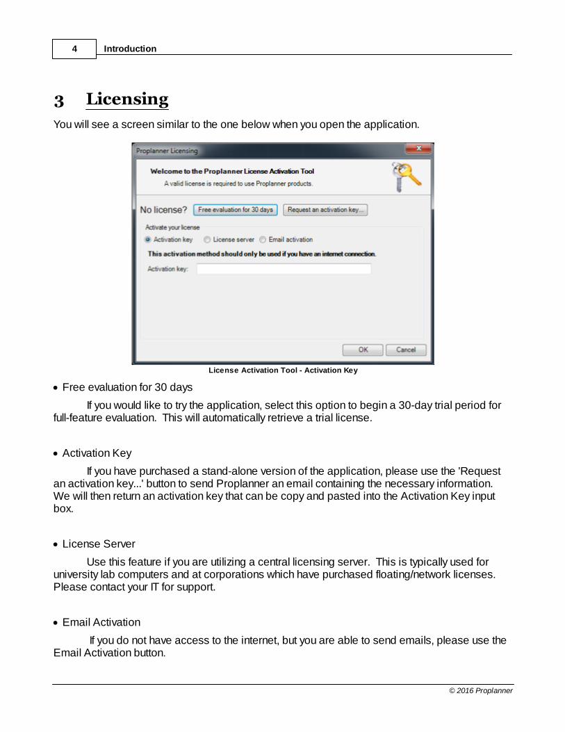
You will see a screen similar to the one below when you open the application.
License Activation Tool - Activation Key
· Free evaluation for 30 days
If you would like to try the application, select this option to begin a 30-day trial period forfull-feature evaluation. This will automatically retrieve a trial license.
· Activation Key
If you have purchased a stand-alone version of the application, please use the 'Requestan activation key...' button to send Proplanner an email containing the necessary information. We will then return an activation key that can be copy and pasted into the Activation Key inputbox.
· License Server
Use this feature if you are utilizing a central licensing server. This is typically used foruniversity lab computers and at corporations which have purchased floating/network licenses. Please contact your IT for support.
· Email Activation
If you do not have access to the internet, but you are able to send emails, please use theEmail Activation button.

5
© 2016 Proplanner
License Activation Tool - Email Activation
If you have any issues or questions in regards to obtaining a license for the application, pleasecontact [email protected].
4 Getting Started
4.1 Preparing and Loading the DrawingWPP can work in either Engineering (Foot-Inch) or Decimal (Metric) units. By default, theapplication will assume that if your drawing is set to Engineering units (Done with the Unitscommand in AutoCAD) that your base unit is 1 inch in size. If your drawing is set to Decimalunits, then Proplanner will assume that your base drawing unit is 1 millimeter. Once the WPP isrunning, you can reset your default base units (to Inches, Millimeters or Meters) in the Licensing/Settings tab if the selected default is incorrect.
AutoCAD Note: Remember that if you use the AutoCAD UNITS command to change your drawing units, you willlikely need to set your drawing limits (size) by using the AutoCAD LIMITS command. You will then need to followthe limits command with the ZOOM ALL command in order to ensure that you are viewing the entire work area.
Since WPP reads the distance from your drawing, it is important that the drawing is created inactual size. This means that if the distance between a table and a box is 3’6” in the real worldthen the drawing needs to be created such that the table is 42 base units from the box (in foot-inch units of course).
The drawing does not need to be highly detailed for WPP to work. Essentially, the drawingneeds to contain enough detail so that the WPP user can determine where locations specified inthe operator routing would be located within the workplace.

Getting Started6
© 2016 Proplanner
4.2 Preparing the RoutingThe workplace routings can be defined in another application (such as MS Excel) and importedinto WPP, or the routings can be defined within the WPP application. If you wish to create yourrouting file in MS Excel, it is best to first import the stationary or moving.csv files into Excel andmodify them in an effort to ensure that the file format is correct. Documentation on the format ofeach field in this file can be found in the appendix of this manual.
You may define a workplace routing within WPP by adding and Inserting lines within the routingeditor. Make certain to use unique element numbers for each row, and to use the proper elementcode for a row (W for walking routes and P or M for process times, etc). Also do not forget tospecify a location in the From field for all processing rows in order to tell WPP where theprocessing is to occur.
4.3 Conducting the AnalysisNow that your drawing is drawn to actual scale and your routing has been created, you are readyto select the Calculate command on the main routings window. Calculate will create youroperators for you and will also ensure that all locations (From and To) specified in the routingsare actually located within your drawing. If any routing locations are missing, WPP will promptyou to locate those within the drawing. Once all locations have been specified, WPP will updatethe walk times and distances in the routing editor and will compute the summary distance, timeand lean information in the results window and on the LEAN and Ergonomics Charts.
Selecting the “Save As” button will save your results out to a file. The input routing data andoutput results data are stored in the same file. This file is a simple comma-delimited text file thatis easy to import into a word processor or spreadsheet.

Conducting the Analysis 7
© 2016 Proplanner
5 Reference Section
Routings Tab
Locations Tab
Paths Tab
Stations Tab
Operators Tab
Parts Tab
Animate Tab
Lean Tab
Ergonomics Tab
Reports Tab
Sequencing Tab
Licensing/Settings Tab
Reference Section8
© 2016 Proplanner
5.1 Routings Tab
Routings Tab
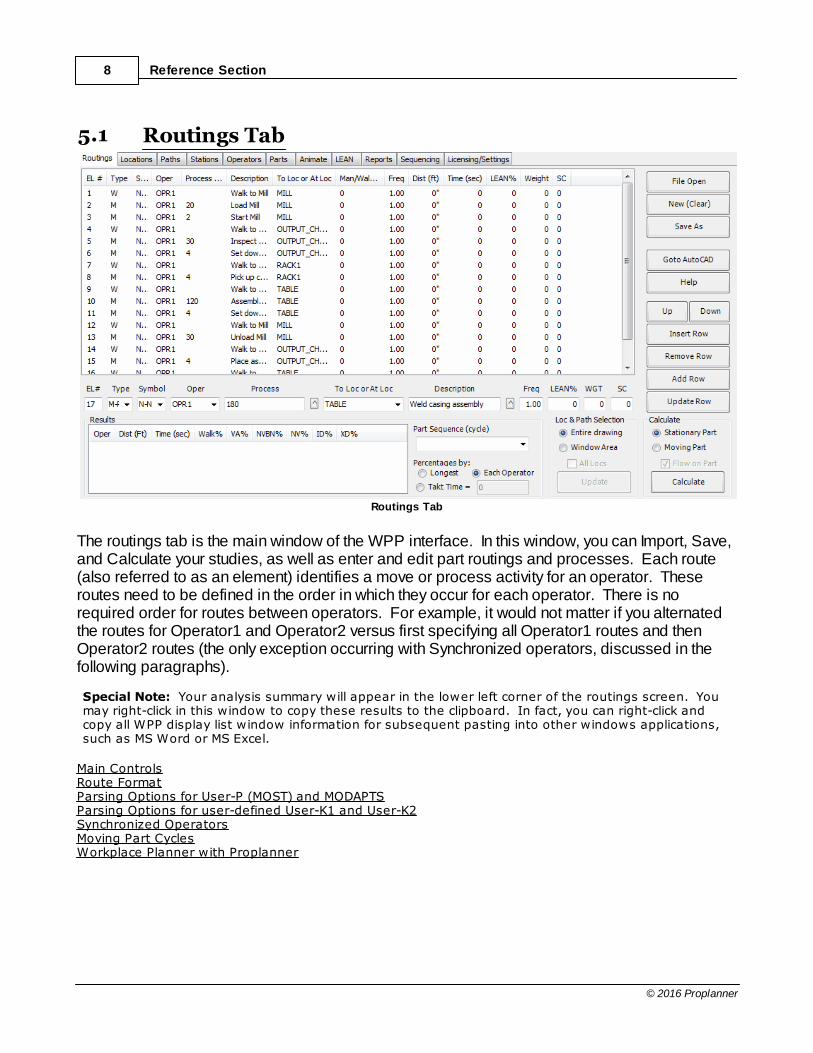
The routings tab is the main window of the WPP interface. In this window, you can Import, Save,and Calculate your studies, as well as enter and edit part routings and processes. Each route(also referred to as an element) identifies a move or process activity for an operator. Theseroutes need to be defined in the order in which they occur for each operator. There is norequired order for routes between operators. For example, it would not matter if you alternatedthe routes for Operator1 and Operator2 versus first specifying all Operator1 routes and thenOperator2 routes (the only exception occurring with Synchronized operators, discussed in thefollowing paragraphs). Special Note: Your analysis summary will appear in the lower left corner of the routings screen. Youmay right-click in this window to copy these results to the clipboard. In fact, you can right-click andcopy all WPP display list window information for subsequent pasting into other windows applications,such as MS Word or MS Excel.
Main ControlsRoute FormatParsing Options for User-P (MOST) and MODAPTSParsing Options for user-defined User-K1 and User-K2Synchronized OperatorsMoving Part CyclesWorkplace Planner with Proplanner

Routings Tab 9
© 2016 Proplanner
5.1.1 Main Controls
File Open: Loads the routing file into the routing editor. The import control will also set the CalcStationary/Moving Part option, and read the drawing for location text, walk paths, and part pathsand fill their associated displays. New (Clear): Clears the current routings list, so that new routings may be entered. Save As: Saves the routings in the editor to a file, along with the units of the study and anyresults in the lower-left results window. Goto AutoCAD: Hides the WPP Modal window and displays a smaller Modeless editingwindow. This command is used when you need to work in the AutoCAD editor environment butwish to return to the WPP application and retain your information. The Modeless window (shownbelow) will appear in the far upper-left corner of the AutoCAD window. The controls includedwithin this modeless window are discussed in their respective sections (i.e. Locations, Paths,etc.)
Modeless Window Displayed
After Clicking Goto AutoCAD
Calculate: The calculate button performs the distance and time calculations and generates andupdates the flow paths. Calculate first looks in the drawing to see that all of the referenced locations exist. If somelocations that appear in the routing, do not appear in the drawing, then WPP will prompt the userto enter each location. In this case, the user will be prompted to select the calculate button againto resume the calculate procedure once all of the input locations have been specified. Calculate also computes the trace information needed for the Animation, and thus calculate mustbe run prior to viewing the Animation.
Stationary Part or Moving Part: Determines which calculate method to use. Forexample, if a file containing relative part locations (i.e. @L5) would be calculated withStationary Part option, then WPP will prompt the user for the location @L5 which will bereferred to thereafter as a fixed location. Likewise, calculating a Stationary routing filewith the Moving Part option will actually work the same as if it were calculated with the

Reference Section10
© 2016 Proplanner
Stationary option. Flow on Part: This checkbox is available for selection when the Moving Part option ischosen. By default, this option is selected on, which means that WPP will add flowdistances for the operator when they are working on the moving part (and thus movingwith the part). Checking this option off will tell WPP to ignore reporting walk distances forthe worker when traveling with the part (i.e. riding the conveyor). Obviously, the totaloperator times will be reported identically in either situation.
Part Sequence (cycle): This button selects which single cycle or all to show results and leanvalues for.
Percentage: Chooses the value by which to calculate the walk, lean, and delay percentages.Each Operator – Uses the actual cycle time computed for each operator. Longest – Takes the longest cycle time of the operators in the results window and sets
this as the cycle time for each operator. Internal delay time is then added for the operators withthe shorter cycle times.
TAKT Time – Allows the user to specify a line TAKT time and then sets this as eachoperator’s individual cycle time. Note that the TAKT time needs to be larger than any of theoperator cycle times.
Loc&Path Selection: Determines if flow paths, part paths, locations, labels and arrows are tobe evaluated and modified for the entire drawing (in the case of one workplace per drawing) orfor a selected window area within the drawing.
All Locs Option: the All Locs option allows WPP to use reference locations outside of thewindows selection area (only applicable if window-area is selected).
Routing Editor Controls
Insert Row: Inserts a row above the selected row and copies the information from the inputboxes below the routing display into this new row as a default starting point.Remove Row: Removes the selected row.Add Row: Takes the data in the input boxes below the routing display and adds them to the endof the routing file.Update Row: Takes the data in the input boxes below the routing display and updates them tothe selected routing in that display.Up or Down : Moves the selected row, up or down one row.Description (shown below): Is where the general description and those for the left and righthand processes are stored.
General Description
The up arrow to the right of the text field can be clicked to open a new description window. In thecase of some time standards, such as MTM-B, MTM-UAS or MOST, and non-predeterminedtime, it is optional to put the process description in the description field if it involves more than

Routings Tab 11
© 2016 Proplanner
one statement. In this situation(MTM), it is necessary to put the word DESC, /DESC or DESC/DESC in the Process field of the routing to direct the parser to look for codes in the left hand,right hand or left and right hand description fields respectively.
Process Description Field
Upon selecting the carrot next to the description field, the user can input both right and left handdescriptions as seen below.
Results Window in lower left of Routings tab
Oper: Operator for which the results are shown.Dist: Distance being traveled for entire process.Time: Total time of operations or time of each cycle.Walk%: Percent of total time spent walking.VA%: Value-added percent.NVABN%: Non-value-added but necessary.NV%: Non-value-added percentID%: Internal Delay is time spent waiting on a machine or synchronized operator.XD%: External Delay is time spent waiting on a part to reach the station.
Routings Tab - Results Window

Reference Section12
© 2016 Proplanner
5.1.2 Route Format
EL# - Element Number, used to synchronize specific element routings (rows) in WPP withother applications – such as Proplanner. If you are having the WPP compute distancesfor Walk and Hand oriented processes which you wish to re-import back to Proplanner, orother applications, it is recommended that you not modify these numbers for existingroutings. Proplanner will automatically insert an asterisk “*” for all new routings. Type – Element TypeNOTE: When defining your process elements, your entire routing file must useEITHER "P/M/W-type" or "I-type" elements. Do not combine a routing file withboth types of elements.
EITHER· P or M or T or X – Manual or Automated process element. The WPP will attempt to
parse the text in the Process field upon Calc if a parser type has been selected. The P,M and T types are for different processes (machine dependent, operator dependent,etc) as specified by MTM standards. The X element tells the program to ignore theparsing of the process code for that element line.
· W – Walk move, tells WPP to compute the walk distance in Feet or Meters. The WPP
will also parse this element and attempt to use the computed distance in thecomputation of time for that element code upon Calc if a parser type has been selectedand if text is entered into the Process Field. [A walk type code is optional for W typeelements]
OR· I – Integrated Walk to, and Process at, element, tells WPP to compute the walk distance
in Feet or Meters (from the operator’s previous location to this new location specified inthe From field) and then apply the process time (at this location) as specified in theprocess field. With the Integrated element type, you do not specify the process time inthe Time field (as you do with the M,P,T or X element type). Instead, you specify yourtime in the Process field, according to the rules for specifying time in this field(discussed in the process section below).
· A - Activity Header (Not Fully Implemented). This provides for the future opportunity todefine elements within an activity and have the individual element times beautomatically aggregated into the Activity time. The WPP application will only evaluatethe Element rows, and then update the Activity row with the aggregated time values.
· H – Hand move, tells WPP to compute the distance in inches (if output Feet) or
millimeters (if output Meters) and replace for distance in hand move code (such asReach or Move in MTM-1). The WPP will attempt to parse the text in the Process fieldupon Calc if a parser type has been selected. This feature is not yet implemented.
· S- Synchronized Move indicates that this task (Walk or Process) cannot begin until all of
the operators who are being synchronized have completed their last task prior to the
Routings Tab 13
© 2016 Proplanner
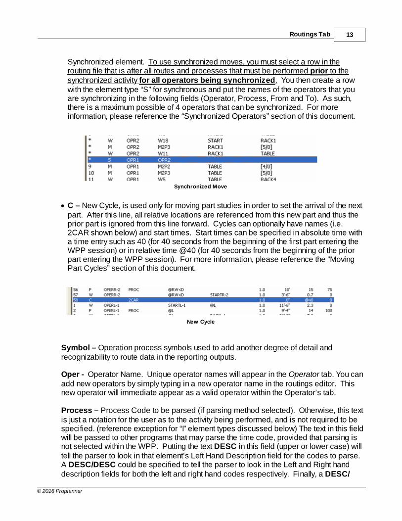
Synchronized element. To use synchronized moves, you must select a row in therouting file that is after all routes and processes that must be performed prior to thesynchronized activity for all operators being synchronized. You then create a rowwith the element type “S” for synchronous and put the names of the operators that youare synchronizing in the following fields (Operator, Process, From and To). As such,there is a maximum possible of 4 operators that can be synchronized. For moreinformation, please reference the “Synchronized Operators” section of this document.
Synchronized Move
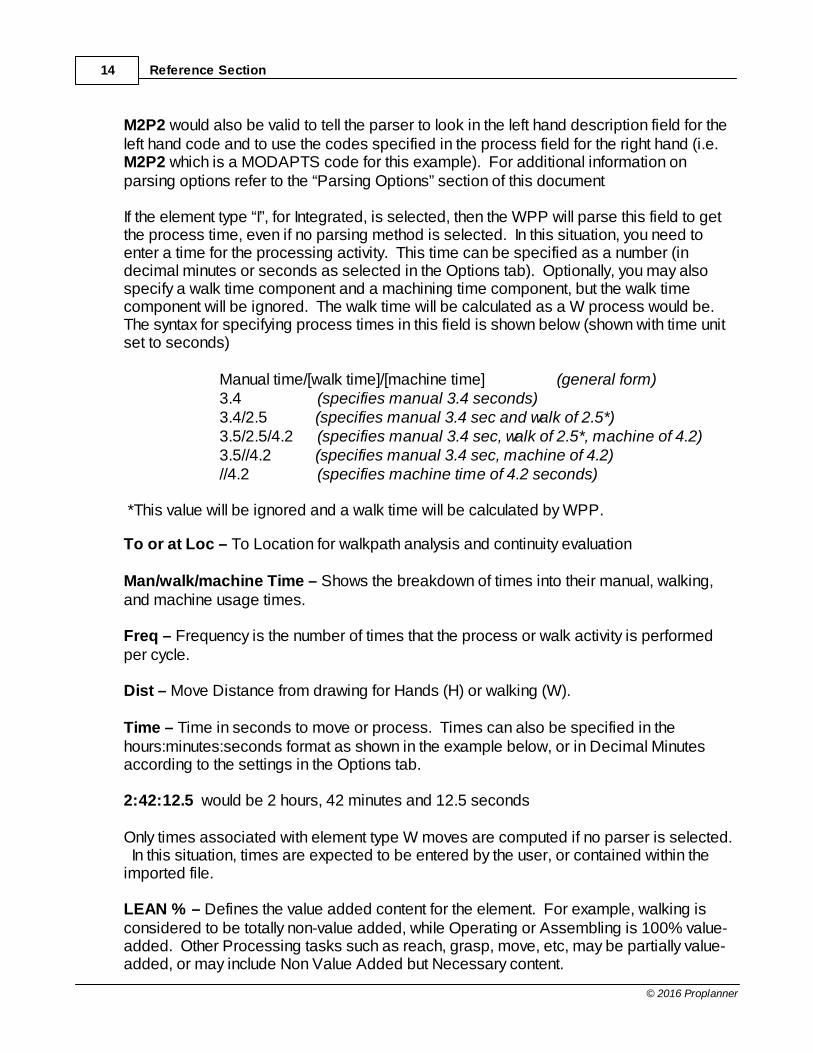
· C – New Cycle, is used only for moving part studies in order to set the arrival of the nextpart. After this line, all relative locations are referenced from this new part and thus theprior part is ignored from this line forward. Cycles can optionally have names (i.e.2CAR shown below) and start times. Start times can be specified in absolute time witha time entry such as 40 (for 40 seconds from the beginning of the first part entering theWPP session) or in relative time @40 (for 40 seconds from the beginning of the priorpart entering the WPP session). For more information, please reference the “MovingPart Cycles” section of this document.
New Cycle
Symbol – Operation process symbols used to add another degree of detail andrecognizability to route data in the reporting outputs.
Oper - Operator Name. Unique operator names will appear in the Operator tab. You canadd new operators by simply typing in a new operator name in the routings editor. Thisnew operator will immediate appear as a valid operator within the Operator’s tab. Process – Process Code to be parsed (if parsing method selected). Otherwise, this textis just a notation for the user as to the activity being performed, and is not required to bespecified. (reference exception for “I” element types discussed below) The text in this fieldwill be passed to other programs that may parse the time code, provided that parsing isnot selected within the WPP. Putting the text DESC in this field (upper or lower case) willtell the parser to look in that element’s Left Hand Description field for the codes to parse. A DESC/DESC could be specified to tell the parser to look in the Left and Right handdescription fields for both the left and right hand codes respectively. Finally, a DESC/
Reference Section14
© 2016 Proplanner
M2P2 would also be valid to tell the parser to look in the left hand description field for theleft hand code and to use the codes specified in the process field for the right hand (i.e. M2P2 which is a MODAPTS code for this example). For additional information onparsing options refer to the “Parsing Options” section of this document If the element type “I”, for Integrated, is selected, then the WPP will parse this field to getthe process time, even if no parsing method is selected. In this situation, you need toenter a time for the processing activity. This time can be specified as a number (indecimal minutes or seconds as selected in the Options tab). Optionally, you may alsospecify a walk time component and a machining time component, but the walk timecomponent will be ignored. The walk time will be calculated as a W process would be.The syntax for specifying process times in this field is shown below (shown with time unitset to seconds) Manual time/[walk time]/[machine time] (general form) 3.4 (specifies manual 3.4 seconds) 3.4/2.5 (specifies manual 3.4 sec and walk of 2.5*) 3.5/2.5/4.2 (specifies manual 3.4 sec, walk of 2.5*, machine of 4.2) 3.5//4.2 (specifies manual 3.4 sec, machine of 4.2) //4.2 (specifies machine time of 4.2 seconds) *This value will be ignored and a walk time will be calculated by WPP.
To or at Loc – To Location for walkpath analysis and continuity evaluation Man/walk/machine Time – Shows the breakdown of times into their manual, walking,and machine usage times. Freq – Frequency is the number of times that the process or walk activity is performedper cycle. Dist – Move Distance from drawing for Hands (H) or walking (W). Time – Time in seconds to move or process. Times can also be specified in thehours:minutes:seconds format as shown in the example below, or in Decimal Minutesaccording to the settings in the Options tab. 2:42:12.5 would be 2 hours, 42 minutes and 12.5 seconds Only times associated with element type W moves are computed if no parser is selected. In this situation, times are expected to be entered by the user, or contained within theimported file. LEAN % – Defines the value added content for the element. For example, walking isconsidered to be totally non-value added, while Operating or Assembling is 100% value-added. Other Processing tasks such as reach, grasp, move, etc, may be partially value-added, or may include Non Value Added but Necessary content.

Routings Tab 15
© 2016 Proplanner
LEAN values are whole numbers (integers) specified from 0 to 100 (inclusive), and mayoptionally include a second part to represent Non Value Added but Necessary content. The first part (before a slash) represents the Value Added content, and the second part(after a slash) represents the Non Value Added but Necessary content. The slash isoptional if there is no Non Value Added but Necessary content. The following examplesrepresent valid syntax for LEAN values. 100 is 100% Value Added100/0 is 100% Value Added (slash and zero at end is optional)50/20 is 50% Value Added and 20% Non Value Added but Necessary/40 is 40% Non Value Added but Necessary0/40 is 40% Non Value Added but Necessary (0 before slash is optional) For I-type elements, the LEAN value percentage only applies to the process timecomponent of the integrated element, as the walk time for the I-type element is alwaysassumed by the WPP to be non-value added. For example, if an I-type element had aprocess time of 12 seconds and a walk time of 5 seconds and if the LEAN percentagewas specified as 50 (i.e. 50%) then the WPP would consider the entire element to have 6seconds of Value Added work content and 11 seconds of Non-Value added work content. Weight – Currently a weight is entered into this field for use by the Ergonomics Evaluator. Weight can be entered as an integer number for walking (Type W) to be used in theCarry Assessment and also with a posture and integer weight value for Lifting in aprocess element. For example, a lift from the floor to the waist for a 10 lb object would berepresented as F10. In addition, a combo-approach can be used if lifting between two orthree zones as shown in the following examples. (FK10 is a lift from the Floor to theShoulder for a 10lb object) (FH10 is a lift from the Floor to above the Head for a 10 lbobject)· F – Lift from Floor to Knuckle height when standing· K - Lift from Knuckle height (just below waist) to shoulder height)· H - Lift over Head from shoulder to above SC – Special Codes field used for process time parsing. Some time estimationlanguages, such as MTM-1 and 4M require the addition of Special Codes that are usedto define attributes of the element such as field of vision, In-Motion and SimultaneousActivities. Currently the MODAPTS and User-P (Most) parsers will assume simultaneousLeft and Right hand motion unless an “L” (must be capital) is put in the SC field, in whichthe program will add both the left and right hand times.

Reference Section16
© 2016 Proplanner
5.1.3 Parsing Options for Used-P (MOST) and MODAPTS
The MOST and MODAPTS predetermined work measurement systems are parameter basedsystems in which the parameter values (numbers) following the parameter codes (letters) aresimply added together in order to determine the appropriate number of TMUs or MODs thatdefine a particular activity. These TMUs, or MODs, are then multiplied by a fractional secondsvalue (shown below) in order to determine time in seconds (or Decimal minutes as specified inthe Options tab). MODAPTS Conversion: 1 MOD = 0.129 SecondsMTM/MOST (User-P) Conversion: 1 TMU = 0.036 Seconds For example, a Move and Place task would be defined in MODAPTS as an M2P2 which wouldevaluate to 4 MODS and thus 0.516 Seconds. For more information on the MODAPTS andMOST language syntax, please contact the user manuals produced by their appropriateorganizations. The WPP application includes special capabilities for parsing these parameter based codes. These capabilities are described below. Left and Right Hand tasks with High or Low skill levelLeft and right hand codes can be specified by simply separating the codes by a slash character /. The parser will use the longest processing time of the left or right and thus assumes a High skilllevel by default. You may also optionally place a capital H in the SC field to signify High skilllevel. If the task is of low skill level and thus the left and right hand codes should be addedtogether (thus these tasks are performed sequentially) then a capital L should be placed in theSC field to signify Low skill level. Partial Code RepetitionPart of the code syntax can be repeated by placing the codes to be repeated in parentheses thatare prefixed by a multiplication factor. For example, in MODAPTS an M2P2 5(W5) would causethe parser to compute 29 MODs where the W5 parameter number would be multiplied by 5. Likewise, in MODAPTS, a 3(M2P2) would evaluate to 12. Simultaneous MotionsPart of the code syntax can be ignored by placing the codes to be ignored in angle brackets(i.e. <>). In some situations you may wish to document a set of simultaneously occurring tasks,but have the parser ignore some of these tasks which can be performed concurrently. Forexample, if the operator was doing a Move and Place task while walking and the walking shouldbe ignored, then the code should be specified as M2P2 <W5>. Direct Time Specification for “I” type elementsAs mentioned in the discussion for I-type elements, the process time must be specified in theprocess field. This can be done by specifying a parse method and including the codes for thatparticular method in this field, or it can be accomplished by specifying the time directly as adirect value as per the format shown below. This format for specifying the process time can beused if no parse method is selected, or if any parse method is selected – even though the

Routings Tab 17
© 2016 Proplanner
following format is not valid for that parse method. Manual time/[walk time]/[machine time] (general form) 3.4 (specifies manual 3.4 seconds) 3.4/2.5 (specifies manual 3.4 sec and walk of 2.5) 3.5/2.5/4.2 (specifies manual 3.4 sec, walk of 2.4, machine of 4.2) 3.5//4.2 (specifies manual 3.4 sec, machine of 4.2) //4.2 (specifies machine time of 4.2 seconds)
Reference Section18
© 2016 Proplanner
5.1.4 Parsing Options for user-defined User-K1 and User-K2
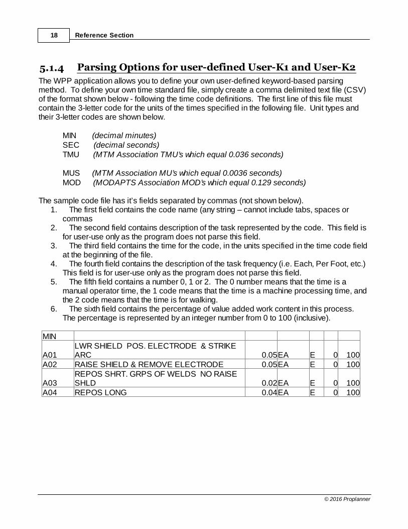
The WPP application allows you to define your own user-defined keyword-based parsingmethod. To define your own time standard file, simply create a comma delimited text file (CSV)of the format shown below - following the time code definitions. The first line of this file mustcontain the 3-letter code for the units of the times specified in the following file. Unit types andtheir 3-letter codes are shown below.
MIN (decimal minutes)SEC (decimal seconds)TMU (MTM Association TMU’s which equal 0.036 seconds) MUS (MTM Association MU’s which equal 0.0036 seconds)MOD (MODAPTS Association MOD’s which equal 0.129 seconds)
The sample code file has it’s fields separated by commas (not shown below).
1. The first field contains the code name (any string – cannot include tabs, spaces orcommas
2. The second field contains description of the task represented by the code. This field isfor user-use only as the program does not parse this field.
3. The third field contains the time for the code, in the units specified in the time code fieldat the beginning of the file.
4. The fourth field contains the description of the task frequency (i.e. Each, Per Foot, etc.) This field is for user-use only as the program does not parse this field.
5. The fifth field contains a number 0, 1 or 2. The 0 number means that the time is amanual operator time, the 1 code means that the time is a machine processing time, andthe 2 code means that the time is for walking.
6. The sixth field contains the percentage of value added work content in this process. The percentage is represented by an integer number from 0 to 100 (inclusive).
MIN
A01LWR SHIELD POS. ELECTRODE & STRIKEARC 0.05EA E 0 100
A02 RAISE SHIELD & REMOVE ELECTRODE 0.05EA E 0 100
A03REPOS SHRT. GRPS OF WELDS NO RAISESHLD 0.02EA E 0 100
A04 REPOS LONG 0.04EA E 0 100

Routings Tab 19
© 2016 Proplanner
5.1.5 Synchronized Operators
The WPP application will allow you to synchronize up to 4 concurrent operators within aworkplace. This feature is most often used when you have tasks that must be performed bymore than one operator concurrently, or when an operator cannot begin a particular task untilanother operator has completed a prior task. Operators can be synchronized in stationary and moving part studies. An operator will wait foranother operator at the last specified location that he/she is routed to prior to the task after thesynchronization element. In moving part studies it is possible that an operator might be waitingon a moving part for another operator and thus this situation should be taken into considerationwhen viewing the animation of synchronized operators in moving part studies. All routes (elements) for synchronized operators must be completed prior to the synchronizationelement before the WPP application will continue on to those tasks listed after thesynchronization element. The order of the tasks specified between operators prior to thesynchronization element can be listed alternately or sequentially as shown in the two examplesbelow.
Sequentially Specified Tasks
Alternatively you could to the following (although this is more difficult to read)
Alternatively Specified Tasks
In both situations, OPR1, and OPR2 will both wait at location TABLE (although they could just aseasily be waiting at two different locations) until both operators are available. When they areboth available, OPR1 will process at the TABLE and OPR2 will also perform its activity (not

Reference Section20
© 2016 Proplanner
shown in the current display).
Routings Tab 21
© 2016 Proplanner
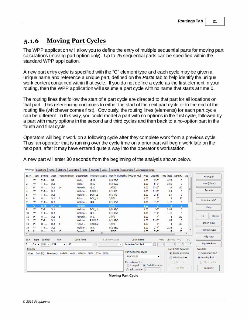
5.1.6 Moving Part Cycles
The WPP application will allow you to define the entry of multiple sequential parts for moving partcalculations (moving part option only). Up to 25 sequential parts can be specified within thestandard WPP application. A new part entry cycle is specified with the “C” element type and each cycle may be given aunique name and reference a unique part, defined on the Parts tab to help identify the uniquework content contained within that cycle. If you do not define a cycle as the first element in yourrouting, then the WPP application will assume a part cycle with no name that starts at time 0. The routing lines that follow the start of a part cycle are directed to that part for all locations onthat part. This referencing continues to either the start of the next part cycle or to the end of therouting file (whichever comes first). Obviously, the routing lines (elements) for each part cyclecan be different. In this way, you could model a part with no options in the first cycle, followed bya part with many options in the second and third cycles and then back to a no-option part in thefourth and final cycle. Operators will begin work on a following cycle after they complete work from a previous cycle. Thus, an operator that is running over the cycle time on a prior part will begin work late on thenext part, after it may have entered quite a way into the operator’s workstation. A new part will enter 30 seconds from the beginning of the analysis shown below.
Moving Part Cycle

Reference Section22
© 2016 Proplanner
Alternatively, you can specify a part’s entry time as 50 seconds relative to a previous part’s entrysuch as shown in the example below, by simply prefixing the time with the @ character.
50 Second Time Prefixed With @
Routings Tab 23
© 2016 Proplanner
5.1.7 Workplace Planner with Proplanner
The Proplanner application can export the Elements of an Activity by using the Export option inthe Activity-Time-Calculated tab. These Elements will be exported to a CSV file of the formatrequired by the WPP application. Likewise, you may import a WPP routing CSV file into theelement list of a Proplanner activity.
In the 2.0 Version of Proplanner (and above) WPP CSV files can be exported from, and alsoimported to, Operations within Proplanner. In this situation, each routing line in the WPPapplication will correspond to an Activity time and thus only Walking time tasks will actually beimported back into Proplanner from the WPP application.
For more information on Using the Workplace Planner with Proplanner please consult theProplanner User Manual.
Reference Section24
© 2016 Proplanner
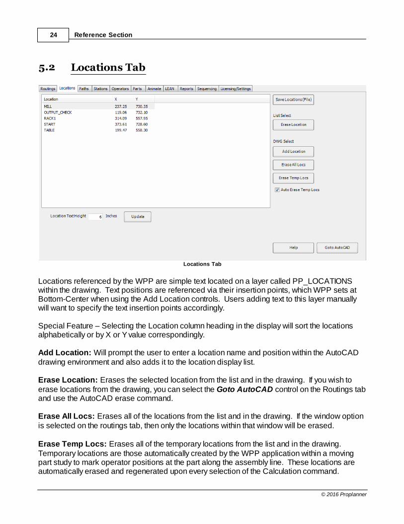
5.2 Locations Tab
Locations Tab
Locations referenced by the WPP are simple text located on a layer called PP_LOCATIONSwithin the drawing. Text positions are referenced via their insertion points, which WPP sets atBottom-Center when using the Add Location controls. Users adding text to this layer manuallywill want to specify the text insertion points accordingly. Special Feature – Selecting the Location column heading in the display will sort the locationsalphabetically or by X or Y value correspondingly. Add Location: Will prompt the user to enter a location name and position within the AutoCADdrawing environment and also adds it to the location display list. Erase Location: Erases the selected location from the list and in the drawing. If you wish toerase locations from the drawing, you can select the Goto AutoCAD control on the Routings taband use the AutoCAD erase command. Erase All Locs: Erases all of the locations from the list and in the drawing. If the window optionis selected on the routings tab, then only the locations within that window will be erased. Erase Temp Locs: Erases all of the temporary locations from the list and in the drawing. Temporary locations are those automatically created by the WPP application within a movingpart study to mark operator positions at the part along the assembly line. These locations areautomatically erased and regenerated upon every selection of the Calculation command.

Locations Tab 25
© 2016 Proplanner
Save Locations (File): Saves the location display to a comma-delimited CSV file in the sameformat as shown in the display. Used for exportation of locations to other applications. TheWPP application does not read these files. Location Text Height/Update: Specifying a new location text height and selecting Update, willchange the size of all text on the PP_LOCATIONS layer.

Reference Section26
© 2016 Proplanner
5.3 Paths Tab
Paths Tab
The Paths tab is the main control for path editing and annotation.
List Select
Erase Path: Selects (in the drawing) the currently selected path from the path display list, andthen deletes it from the drawing and the path display list. The path will be regeneratedautomatically by WPP on the next Calc.
Edit/Redo Path: Selects (in the drawing) the currently selected path from the path display list,which WPP will automatically delete and then prompt the user to select vertices (up to 11vertices to create a maximum of 10 segments) for a new path to replace it. User-defined pathsare replaced by Euclidean paths when WPP creates new paths, such as is done in ALL Movingpart studies or when the “All Paths” option is selected on this path window during stationary partstudies.
Erase Listed Paths: Will erase all the walk flow paths shown in the current list, which are pathsin the Drawing referenced by this routing file.

Paths Tab 27
© 2016 Proplanner
Drawing Select
Erase Path: Allows the user to select a path in the drawing and then deletes it from the drawingand the path display list. The path will be regenerated automatically by WPP on the next Calc.
Query Path: Allows the user to select a path in the drawing and display its properties as shownin the example below.
Query Path Properties
Edit/Redo Path: Allows the user to select a path in the drawing, which WPP will automaticallydelete and then prompt the user to select vertices (up to 11 vertices to create a maximum of 10segments) for a new path to replace it. User-defined paths are replaced by Euclidean pathswhen WPP creates new paths, such as is done in ALL Moving part studies or when the “AllPaths” option is selected on this path window during stationary part studies.
Erase DWG Paths: Will erase all of the walk flow paths in the current drawing regardless of ifthey are referenced by this routing file or not.
Path Arrows
Delete: Deletes all arrows.
Update: Any change to the arrow size or placement option will only occur on the next calc orwhen this Update button is selected.
Path Arrows checkbox: Determines if paths should have arrows.
Path Ends/Path Vertices: Determines if arrows are to be placed at path ends only, or also ateach path vertex.
Arrow Width/Arrow Length: Specifies the size of the arrow for a zero width path. As the pathis scaled larger by the Path Thickness value and the Path Frequency, the arrows for thosespecific paths will be factored accordingly.
Path Labels
Delete: Deletes all labels.
Update: Any change to the label size or placement option will only occur on the next calc or
Reference Section28
© 2016 Proplanner
when this Update button is selected.
Path Labels checkbox: Determines if paths should have labels.
Ends Only: Places labels in the middle of the last segment of the path specifying the totaldistance of that path. If checked off, then labels are placed at every segment also to show thelength of that segment. In this case, the last segment has two distance labels. The one inparenthesis is the total path length, and the alternate one is the segment distance.
Above Line/On Line: Determines if labels are placed center on the line or positioned slightlyabove the line (i.e. text insertion point Center or Bottom-Center) to the center of the line segment.
Label Height: Specifies the height of the label.
Precision: Determines how many decimal places to show in the path distance labels.
On-Calc Options
All Paths/Missing Paths: When All Paths is selected, WPP will first erase all existing paths inthe drawing (including manually generated ones) and replace them with new Euclidean (point-to-point) paths. Selecting only Missing Paths (default) will result in WPP only generating paths notyet existing.
Other
Save Paths (File): Saves the location display to a comma-delimited CSV file in the sameformat as shown in the display. Used for exportation of flow path distances to other applications. The WPP application does not read these files.

Paths Tab 29
© 2016 Proplanner
5.4 Stations Tab
Stations Tab
The Stations Window is where all the part path information for the individual stations is accessedwithin the WPP. The data itself is stored within the part path poly line within the drawing. NOTE:The information within the "Stations" tab is only used when performing Moving-Partstudies. Users who are performing "Stationary" studies need not enter any informationinto this tab. Station: This input box is where the station names are assigned.Description: Allows the user to describe the station for future reference.Start: This is the distance from the beginning of the Part Path line where the station begins.Length: This is the length of the station, starting at the start distance.Update: Updates the station list with the new information.Add: This button adds the station created to the list.Remove: Removes the selected station from the list of available stations.Save to Part Path: Saves the station data into the Part Path line on the AutoCAD drawing.Draw Part Path: Allows the user to draw the path on which the parts will travel. The first point isconsidered the start or zero distance. This would be set as 0 if a station was being defined asstarting here.Import Assignments: Allows for station assignments to be imported as a .csv file.Container Insert: Can be used to create containers for stations.

Reference Section30
© 2016 Proplanner
5.5 Operators Tab
Operators Tab
Operators are automatically listed in the Operators display when they are uniquely specified inthe routings file. The WPP will automatically generate their respective flow path layers (as eachoperator’s flow is generated on a unique layer PP_FLOW-opname) in which all of the operatorinformation is stored on the drawing. In addition, the WPP will generate a default Loaded andUnloaded walk speed from the settings on the Options tab (Default: 4.17 feet/second). The useris allowed to specify a unique layer color for each operator. Calc: Allows the user to turn off the calculation of all walkpath flows for the specified operator. With this option set to off, the walkpaths will not be updated or included in the total walkpathdistance and time calculations, and the operator will not animate. Delay: The delay time is set to 0 by default. This time allows the user to delay the availability ofthe operator within the workplace. A time in seconds may be entered into this field. Thedistance option is allowed for moving part analyses so that workers in downstream stations canbegin work when the part travels the specified distance from the beginning of the line to theirstation. Start Location: Determines if, and where, WPP should begin the operator’s movement prior toassuming the first position specified for that operator in the routing file. A value of NONE(default) tells the WPP to ignore that operator’s initial location. Station: Assigns the operator to a station to prevent the operator from trying to reach locationswithin other work stations.

Operators Tab 31
© 2016 Proplanner
Previous Distance/Next Distance: Sets the distance which an operator is allowed to moveinto the previous and next station in order to intercept the part. This calculation does not take intoaccount the length of the part. if the part is long and at the beginning of the walkpath while theoperator goes to the end of the part, the operator may still walk further into the previousworkstation. This is easily overcome by subtracting the part length from the value entered intothis field or adding an operator delay. Block Name: Allows the user to represent the operators with any individual blocks inserted inthe drawing before the WPP was opened. Special Feature – Changing the name of the operator and selecting the update button willautomatically search and replace all occurrences of that operator name in the routings file. Special Note: Operator names cannot contain any special characters other than dashes andunderscores. (!@#$%^&*) and other non-letter characters are not allowed.
Reference Section32
© 2016 Proplanner
5.6 Parts Tab
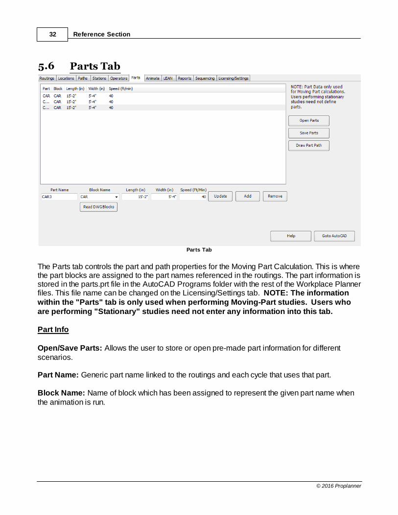
Parts Tab
The Parts tab controls the part and path properties for the Moving Part Calculation. This is wherethe part blocks are assigned to the part names referenced in the routings. The part information isstored in the parts.prt file in the AutoCAD Programs folder with the rest of the Workplace Plannerfiles. This file name can be changed on the Licensing/Settings tab. NOTE: The informationwithin the "Parts" tab is only used when performing Moving-Part studies. Users whoare performing "Stationary" studies need not enter any information into this tab. Part Info Open/Save Parts: Allows the user to store or open pre-made part information for differentscenarios. Part Name: Generic part name linked to the routings and each cycle that uses that part. Block Name: Name of block which has been assigned to represent the given part name whenthe animation is run.

Parts Tab 33
© 2016 Proplanner
Blocks are loaded upon startup of the WPP so if the user adds a new block to the drawing, WPPwill need to be restarted before it will read the block in this drawing. Only valid blocks currentlyavailable within the drawing are shown in the pull-down list. Blocks must be defined with theirdefault direction and insertion point as shown below.
Correct Block Image Of Direction & Insertion Point
SPECIAL NOTE: Backup and Metric or Standard versions of the default blocks can be found onthe installation CD in the folder called SAMPLE FILES. Length: Determines the part length for the A, B, C and D longitudinal offset parameters in therelative part location syntax. (i.e. @L<B references a location in the center of the part 1/3 of theway back from the front. Width: Determines the part width for the W offset parameter in the relative part location syntax. (i.e. @LW references the beginning of the part at the width offset (1/2 width) from the center ofthe part’s flow path. Speed: Determines the speed of the vehicle for animation and Moving Part positionalcalculation. Remember that part speed must be less than operator speed (preferably by at leasta factor of 2) or the operators will not be able to “catch” the part. Draw Part Path: Prompts the user for points that make up a polyline path on the PP_PART-PATH layer. A maximum of 5 segments are allowed for a part path within a workstation. A partpath must be specified before a Moving Part calculation can be performed.

Reference Section34
© 2016 Proplanner
5.7 Animate Tab
Animate Tab
The animate window sets up the animation speed, precision, and repetitions. This tab alsoallows the user to save a trace file that can be used to create an animation in other programs. Move Increment: Determines the resolution of the animation. Smaller values (minimum of0.05) will make the animation run more accurately and more slowly and smoothly. Larger valueswill provide the opposite effect. As such, the final workstation animation time could be differentthan the calculated workstation cycle time - as displayed in the operator results display on theRoutings tab. In this situation, the values in the routings tab are ALWAYS more accurate. Motion Delay: Allows the operator to slow down the animation by inserting a delay betweeneach animation move. This delay value will often be needed when viewing animations in 2D withsimple (i.e. default) operator and part blocks. Save Animation Trace: The Calculation process generates an animation trace events listwhich is used by the animation engine to present the results of the calculation to the user. Thistrace list can be optionally saved to a file for use in evaluating the animation events textually orpossibly for use by other external animation applications. If other applications are to use thistrace file then it is likely that those applications will also need the location and path coordinateinformation stored in the Locations (LOC) and Paths (PTH) files respectively. Together, theLOC, PTH and TRC files provide all of the information required by any external animationapplication to replay the events generated by the WPP application. The WPP application does not read or use a saved trace file, as this information is automatically
Animate Tab 35
© 2016 Proplanner
created by the WPP application when the Calculate option is selected from the main routingstab. Automatic Rerun: Causes the animation to automatically rerun until stopped by the user. Thissetting is ideal for presentation and demonstration purposes where it is desired for theanimation to run continuously in an unattended mode.
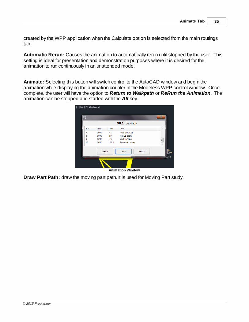
Animate: Selecting this button will switch control to the AutoCAD window and begin theanimation while displaying the animation counter in the Modeless WPP control window. Oncecomplete, the user will have the option to Return to Walkpath or ReRun the Animation. Theanimation can be stopped and started with the Alt key.
Animation Window
Draw Part Path: draw the moving part path. It is used for Moving Part study.

Reference Section36
© 2016 Proplanner
5.8 Lean Tab
LEAN Tab
The LEAN tab charts the percentage of walking, value-added processing, non-value-addedprocessing, non-value-added-but-necessary processing and internal delay for each operator inthe workplace. Part Sequence (Cycle): The dropdown window here again lets the user chose which cycle or
all cycles for which to show the lean percentages.

Lean Tab 37
© 2016 Proplanner
5.9 Ergonomics Tab
Ergonomics Tab
The Ergonomics tab charts the operator safety for the Lift and Carry tasks involving weight andposture defined within the routings. The WPP uses the “SNOOK” tables developed by LibertyMutual Insurance in 1991 and approved by OSHA. The WPP allows the user to compute resultsfor both 75% Females and 75% Males. SHIFT LENGTH – The SNOOK tables require a number of cycles (or repetitions) of the routingperformed over a given period of time. The Shift length determines the total duration of timeduring which the routing is performed. Together with the Task Focus (defined below), and therouting cycle time, the WPP is able to determine the number of repetitions per day over the shiftlength time to determine the safety of the task. TASK FOCUS – The task focus defines the percentage of time during the shift that the operatoris performing the activities defined in the routing. For example, if the operator is working an 8hour shift (as defined in the shift length), but only performs the routing cycle ½ of the time duringthis shift, then the Task Focus value would be 50 to represent 50%.

Reference Section38
© 2016 Proplanner
5.10 Reports Tab
Reports Tab
The Reports tab is where you generate your workstation report. The workstation report includesan image of your workstation, along with workstation header information that you can enter in thetop right of the screen.
Select the Get Image button to get the current view of your workplace. You may need to selectthe Goto AutoCAD button in order to adjust your display such that the workstation view lookscorrect. If using a window select, selecting get image a second time may zoom in more preciselyon the section selected.
Once your view is acceptable; select the Station Report button to generate your report. Using theValue Added Time/Reg. Time option will create the same station report with VA/NVApercentages and times. Another option is the Man/Machine report to demonstrate the differencein manual versus machine work times in the same format as the original station report (note thisreport is available upon request). Once the report is generated, simply select the File Saveoption in the browser window to save your report.
These reports can be set to show both Activities and Elements or either choice separately. Thiswill help the user gauge how much information is needed to be displayed.
(Note the total time calculated on the Station Report does not include the external delay addedby waiting for the next part, only the actual time spent working on this part.)
Reports Tab 39
© 2016 Proplanner
5.11 Sequencing Tab
Sequencing Tab
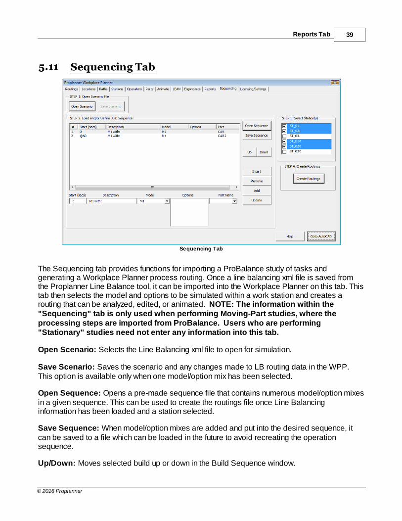
The Sequencing tab provides functions for importing a ProBalance study of tasks andgenerating a Workplace Planner process routing. Once a line balancing xml file is saved fromthe Proplanner Line Balance tool, it can be imported into the Workplace Planner on this tab. Thistab then selects the model and options to be simulated within a work station and creates arouting that can be analyzed, edited, or animated. NOTE: The information within the"Sequencing" tab is only used when performing Moving-Part studies, where theprocessing steps are imported from ProBalance. Users who are performing"Stationary" studies need not enter any information into this tab.
Open Scenario: Selects the Line Balancing xml file to open for simulation.
Save Scenario: Saves the scenario and any changes made to LB routing data in the WPP.This option is available only when one model/option mix has been selected.
Open Sequence: Opens a pre-made sequence file that contains numerous model/option mixesin a given sequence. This can be used to create the routings file once Line Balancinginformation has been loaded and a station selected.
Save Sequence: When model/option mixes are added and put into the desired sequence, itcan be saved to a file which can be loaded in the future to avoid recreating the operationsequence.
Up/Down: Moves selected build up or down in the Build Sequence window.

Reference Section40
© 2016 Proplanner
Insert: Insert’s a row similar to the selected option/model mix above this row. Will useinformation provided in the Sequence Start and Description field instead of the attributes of theselected build if they are different.
Remove: Erases the option/model mix selected from the Build Sequence window.
Add: Adds Line Balancing data for the selected station and model/option mix to the sequence that can later be used to create a routing file to run a WPP simulation.
Update: Updates the selected build with the Sequence Start and Description information in theinput fields to the left of this button.
Station: Selects which work station to simulate from the Line Balancing file that will contain allstations within the plant.
Model: Defines the specific model for which this routings will be made. You can choose differentmixes and add them to the sequence.
Options: Sets the options for which the simulation will be created. You can choose differentmixes and add them to the sequence.
Create Routings: Uses the selected station, model, and options to create the routings file foractivities and operations done within that work station in that scenario. In other words, thisgenerates the actual simulation routing file.

Sequencing Tab 41
© 2016 Proplanner
5.12 Licensing/Settings Tab
Settings Tab
The Licensing/Settings tab is where the licensing codes and expiration dates are set, as well as,the special options available within the application. The Help button will access the on-line helpdocument, which is also available as a PDF file (located in the program directory) for easierprint-out. All entries in this tab window are saved between user sessions.
5.12.1 Process Parsing Options
Process Parsing: Determines if the WPP should attempt to evaluate the Process code columnfor the routings and compute the appropriate process times. MTM-B, MODAPTS, User-P(MOST), and User-K1 or User-K2 (user defined keyword parser) are available in the applicationby default. Users may request the MTM-1, MTM-2, MTM-4M and MTM-UAS standards from theMTM Association, or a Proplanner representative. Remember that Proplanner’s Timeestimation module will also parse these Process codes and can Import and Export files from/tothe WPP. Proplanner can import/export a Workplace Planner study as ELEMENTS of anACTIVITY, or as ACTIVITIES of an OPERATION, whereby the walk tasks are assigned as delaysto the ACTIVITY links within the OPERATION. For additional information on parsing optionsrefer to the “Parsing Options” section of this document. Also, for additional information on theinterface between Proplanner and the Workplace Planner, refer to the “Workplace Planner withProplanner” section of this document.
When any of the Keyword-based parse methods (MTM-B, MTM-UAS, MTM-2, User-K1 or User-K2) is chosen, you may select the button just to the right of the Process field (as shown below)to pull-up the process list. This process list is a view of your process standards file and it letsyou select a particular standard, so that you do not need to type it in.

Reference Section42
© 2016 Proplanner
· The standard times in the list will be in the units of the list (i.e. Minutes, Seconds, TMU’s,MU’s, MOD’s) and will be automatically converted into the current WPP session units(Minutes or Seconds) upon selection.
· If you want to override the process time as specified in your standards file, you can do soby selecting the Process Type “X”. This will tell the parser to ignore parsing the processcode in that element.

Licensing/Settings Tab 43
© 2016 Proplanner
For those standards that are specified in distance, or per-item, you can use the frequency field tofactor the number of occurrences of the process type within your element line.
Selecting the option to Include Description will copy the standard’s description into the elementdescription field within the routing editor.
Process List

Reference Section44
© 2016 Proplanner
Use Standard Derived Walk Time: If this option is selected, then the operator speed(specified in the Operators tab) is ignored and the distance is used to compute the walk time byusing the user-selected predetermined time system (MODAPTS or USER-P).
Increment MODAPTS walk by 5 MODS: If the MODAPTS time parsing is selected, then theapplication will automatically round up walk distances in increments of 5 MODS. Even if thisoption is not checked, the application will never report a walk time of less than 5 MODS.
Example:
Increment by 5 MODS
Actual ON OFF
2.5 5 5
7 10 7
5.12.2 Time Units
Hours:Minutes:Seconds: Allows for the entry (by the user) and output (by the application) fortime in an Hours:Minutes:Seconds format. As such, a time of 91.6 will be automaticallyinterpreted as 1:31.6 (one minute, thirty one point six seconds).
Hours:Decimal Minutes: Allows for the entry (by the user) and output (by the application) fortime in an Hours:Minutes format. As such, a time of 91.6 will be automatically interpreted as1:31.6 (one hour, thirty one point six minutes).
5.12.3 Walk Speed Options
The WPP walk speed options give you extensive flexibility in specifying workplace walk timeestimates. Note: these time calculations are bypassed if the user selects the USERSTANDARD DERIVED WALK TIME option AND if the parser is set to the MODAPTS or USER-P.
Start Walk Time (secs): The time for the first foot or 1/3 meter of walk distance. If this value iszero, then the WPP will use the operator’s Loaded/Unloaded speed for this initial distance.
Min Dist: The minimum distance for any move. If this value is zero, then the WPP will use aminimum distance of 1 Inch or 1 millimeter.
Differentiate After: The distance (after the first foot or 1/3 meter) for the WPP to use for theBEGINNING WALK SPEED, after which the WPP will use either the Loaded or Unloadedspeed. If this value is zero, then the WPP will use the operator’s Loaded/Unloaded speed for thedistance after the first foot or 1/3 meter.
Beginning Walk Speed: The speed used by the WPP for the distance up to and including thedistance specified in the DIFFERENTIATE AFTER FIELD. A value of zero in this field will causethe WPP to use the operator’s Loaded/Unloaded speed for this initial distance.
Default UnLoaded Walk Speed: The default speed that the WPP will use for walking without aload when new operators are added by the WPP.
Default Loaded Walk Speed: The default speed that the WPP will use for walking with a load

Licensing/Settings Tab 45
© 2016 Proplanner
when new operators are added by the WPP.
Consider Loaded Above: If the routing element’s weight is GREATER THAN this value, thenthe WPP will use the Loaded Speed for that operator, otherwise the WPP will use the Unloadedspeed.
Times in Feet/Second
Example Default
0.72 0 Start Walk Time
3 0 Min Dist
6 0 Differentiate After
2.78 0 Beginning Walk Speed
4.17 5 Default UnLoaded Walk Speed
3.33 4 Default Loaded Walk Speed
5 5 Consider Loaded above
Reference Section46
© 2016 Proplanner
5.12.4 Moving Part Options5.12.4.1 Start Position if First Loc on Part
Determines the FROM location when the To/At location for the First element is a relative locationon the part, and/or when the first element’s type is Integrated.
Start at Op Start Location: The WPP will start the operator at that Operator’s START locationas specified in the Operator’s tab.
Start at last Element Location: If the location of the last element is not a relative location onthe part, then the WPP will start the operator at this location and then move to the locationspecified in the first element. If the last element’s location is on the part, then the WPP willdefault to using the Operator’s Start location as the from location for the first element.5.12.4.2 Part Grid
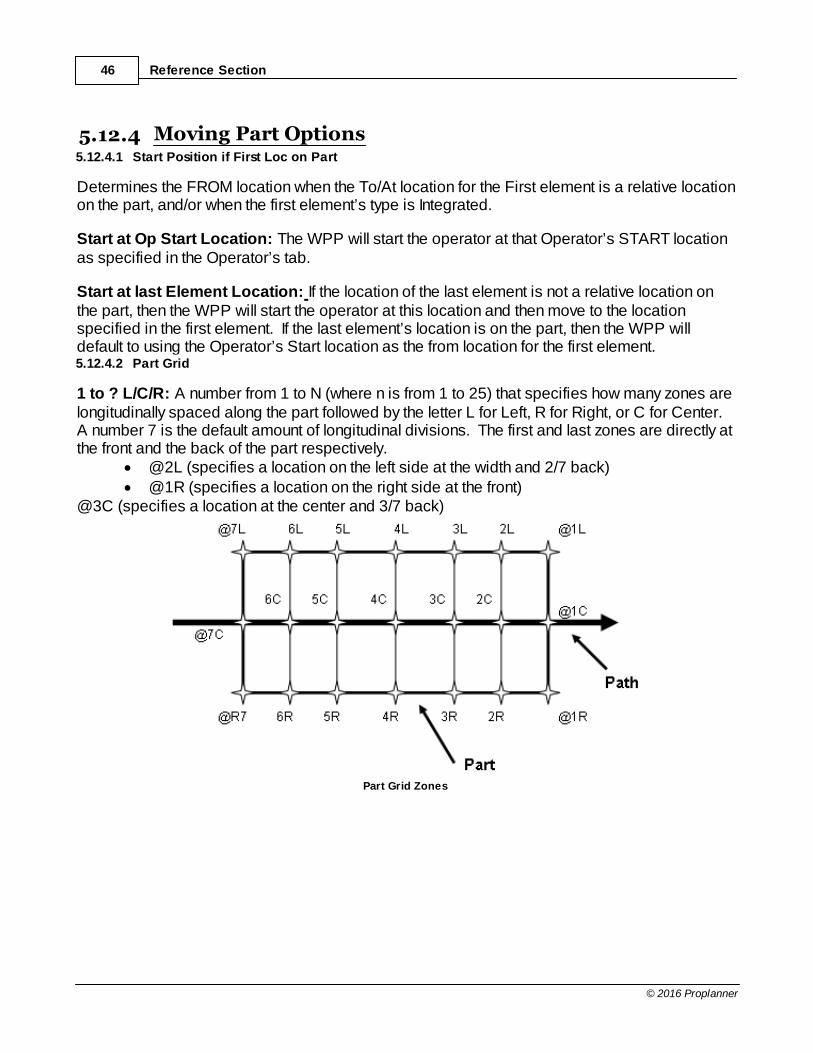
1 to ? L/C/R: A number from 1 to N (where n is from 1 to 25) that specifies how many zones arelongitudinally spaced along the part followed by the letter L for Left, R for Right, or C for Center. A number 7 is the default amount of longitudinal divisions. The first and last zones are directly atthe front and the back of the part respectively.
· @2L (specifies a location on the left side at the width and 2/7 back)· @1R (specifies a location on the right side at the front)
@3C (specifies a location at the center and 3/7 back)
Part Grid Zones

Licensing/Settings Tab 47
© 2016 Proplanner
R/L/W A to ?: The method to specify a location on a Moving part. L-Left, R-Right, W-Width andthen a letter from A to Z that specifies how many zones are longitudinally spaced along the part. The letter D is the default. The first and last zones are directly at the front and the back of thepart respectively. You must always place an ‘At’ symbol (@) at the beginning of this locationname. You may optionally replace the letter ‘W’ with a distance from the center of the part out tothe side (Feet or Meters). You may also optionally replace the longitudinal letters (i.e. A to D)with a distance from the front of the part to the back. The examples below assume the default of A to D and units of Feet
· @LW<B (specifies a location on the left side at the width and 1/3 back)· @R (specifies a location on the right side at the front)· @RW<2.5 (specifies a location on the right side at the width and 2.5 feet back)
@R1.2<C (specifies a location on the right side 1.2 feet from the center and 2/3 of the wayback)
Zones On A Moving Part
5.12.5 Other Settings
Output Units: Sets the default distance units for output information from the program.
Base Drawing Units: Sets the default distance units to read distances from the drawing.
Location Text Layer: The layer that the WPP will look to find location text. Default isPP_LOCATIONS.
Path Thickness: Determines how thick a path should be for each unit of travel frequencyspecified in the flow path routing. A value of zero will generate dimensionless thick flow lines. Path thicknesses are generated during a Calc command.
Automatically Renumber Elements: If this is set, then the program will constantly renumberyour elements sequentially. (NOTE: some applications that you interface with, my require theelement numbers not to be changed in the WPP application.)
Always route last loc to first loc: Automatically route the last location in the element list to thefirst location.

Reference Section48
© 2016 Proplanner
Line Delimiter: This setting allows the user to select either the comma or semi-colon for thedelimiter it uses to separate information in the input files. The default comma separated files arenot always standard for foreign numeric notations that use commas instead of periods.
Automatically Erase Temp Locations: Automatically erase the temporary locationsgenerated in the drawing.
Parts File Name: The default directory and file for the parts file used in WPP.
Save Settings: Saves the values specified in the Application Settings and Defaults frame sothat they will be default for all subsequent sessions.
Licensing/Settings Tab 49
© 2016 Proplanner
6 Tutorial
There are three tutorials to help you become familiar with Proplanner's Workplace Planner: These tutorials (both Metric and FootInch versions) are located in subdirectories within the HELPsubdirectory located in the directory where the program was installed (typically c:\program files\proplanner\autocad programs).
The Metric tutorials (base unit is millimeter) are available in two forms (comma and semi-colondelimited). The comma delimited metric tutorials are for those countries who use the samenumber format as the United States (i.e. 1,200.52), and the semi-colon tutorials are for thosecountries (Germany, Italy, France, Sweden, etc.) who reverse the comma and decimal point (i.e.1.200,52).
Stationary Part Analysis
Moving Part Analysis
Sequencing from Line Balance data

Tutorial50
© 2016 Proplanner
6.1 Stationary Part Analysis
STEP 1: To get started, make sure all other drawings in AutoCAD are closed. If you havealready been working in Workplace Planner, click the New (Clear) button in the Routings tab. Then Open the file “WALKPATH-2D.DWG”. You should be able to see the ProplannerApplications menu on your screen. If not, you will need to load this menu using the MenuInstallation Guide included in the Install.pdf. STEP 2: Select the “W” icon button in the Proplanner ribbon.
Stationary Part Analysis 51
© 2016 Proplanner
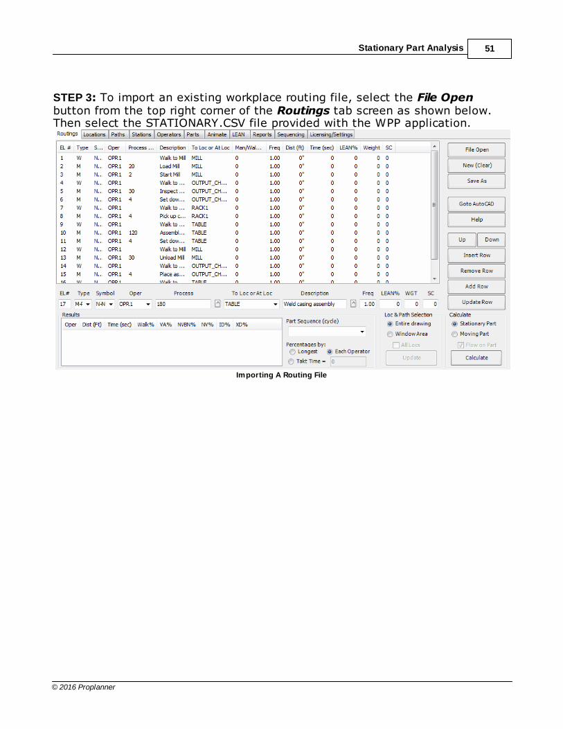
STEP 3: To import an existing workplace routing file, select the File Openbutton from the top right corner of the Routings tab screen as shown below.Then select the STATIONARY.CSV file provided with the WPP application.
Importing A Routing File

Tutorial52
© 2016 Proplanner
STEP 4: You should now be able to select the Calculate button in the bottom right of the screento analyze the initial workplace layout. If it prompts that not all locations are present, add them byclicking on a location on the drawing. If an error states that a station has no length, go to thestations tab and update the length to 40'. The results of this Calculate can be seen in theDistance and Time columns in the right side of the routings window and in the Results Area inthe bottom left corner. In addition, the flow lines should have been drawn in your layout as shownbelow. Depending on your version of AutoCAD and the specific tutorial files that were loaded,the drawing and routings may vary.
Drawing

Stationary Part Analysis 53
© 2016 Proplanner
STEP 5: You can now select the Locations tab to see the location text that Proplanner found onthe PP_LOCATIONS layer within the drawing. This text has already been added for you,however you could add additional location(s) by selecting the Add Location button in the middleright of this screen, under DWG Select, or by going into AutoCAD and simply placing textmanually on this layer.
Locations Tab - Adding Location
STEP 6: You can now select the GotoAutoCAD to see the walk paths that were drawn byProplanner in the workplace between the locations. Proplanner automatically generates flowpaths using Euclidean (point-to-point) lines.
Tutorial54
© 2016 Proplanner
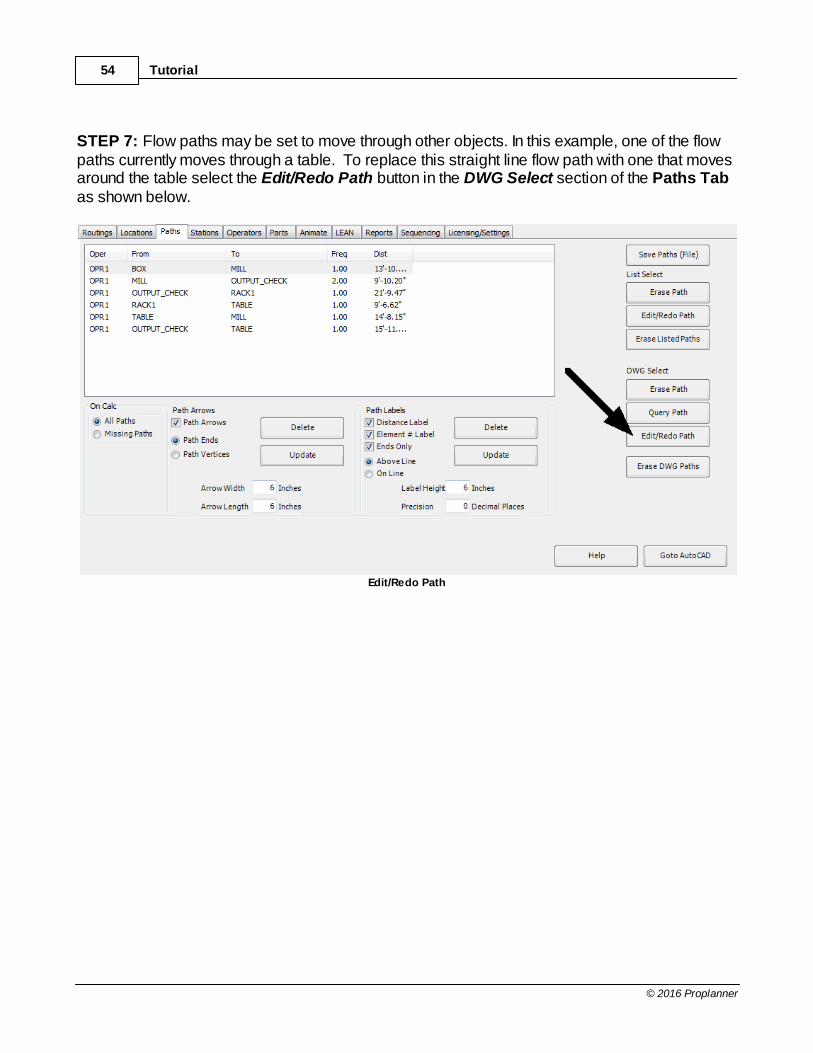
STEP 7: Flow paths may be set to move through other objects. In this example, one of the flowpaths currently moves through a table. To replace this straight line flow path with one that movesaround the table select the Edit/Redo Path button in the DWG Select section of the Paths Tabas shown below.
Edit/Redo Path
Stationary Part Analysis 55
© 2016 Proplanner
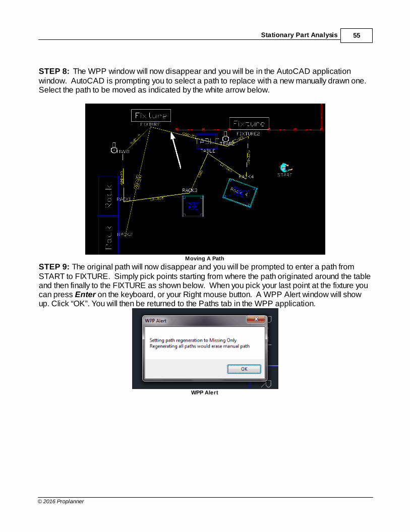
STEP 8: The WPP window will now disappear and you will be in the AutoCAD applicationwindow. AutoCAD is prompting you to select a path to replace with a new manually drawn one. Select the path to be moved as indicated by the white arrow below.
Moving A Path
STEP 9: The original path will now disappear and you will be prompted to enter a path fromSTART to FIXTURE. Simply pick points starting from where the path originated around the tableand then finally to the FIXTURE as shown below. When you pick your last point at the fixture youcan press Enter on the keyboard, or your Right mouse button. A WPP Alert window will showup. Click “OK”. You will then be returned to the Paths tab in the WPP application.
WPP Alert

Tutorial56
© 2016 Proplanner
STEP 10: To evaluate the impact of this change. Simply select the Routings tab at the top andre-select the Calculate button. Make sure that the study is set to stationary part Calculate in thebottom right of the routings tab. Your new total walk distance and time will be updated, and yourpaths will look like those shown below. If the distances cannot be seen, within the paths tab thereare options to increase arrow width and height, as well as path labels. Clicking update willchange the labels (lengths) automatically to the new height.
Calculate
STEP 11: Now select the Operators tab to see the operator in your study. This window is filledwhen you load, or define, your routings. Every time that you use a unique operator name, it willappear in this window. From this window, you can set the walking speed of your operators andthe color of their flow paths. An ability to set the maximum distance traveled into the previousworkstation to work on a moving part has also been included here.
Operators Tab

Stationary Part Analysis 57
© 2016 Proplanner
STEP 12: Select the Operators tab and select the Person Block name of “PERSON” or"PP_PERSON" in the pull-down box shown highlighted below. Next, select the Animate tab tosee the animation options. Finally, select the Animate button at the top of the screen to watchthe operator perform the work in 2D.
Person Block Name
Animation
Tutorial58
© 2016 Proplanner
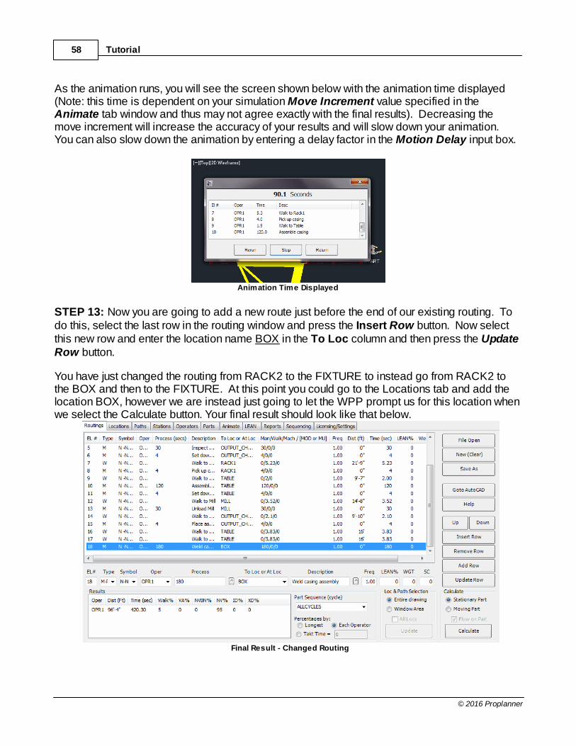
As the animation runs, you will see the screen shown below with the animation time displayed(Note: this time is dependent on your simulation Move Increment value specified in theAnimate tab window and thus may not agree exactly with the final results). Decreasing themove increment will increase the accuracy of your results and will slow down your animation. You can also slow down the animation by entering a delay factor in the Motion Delay input box.
Animation Time Displayed
STEP 13: Now you are going to add a new route just before the end of our existing routing. Todo this, select the last row in the routing window and press the Insert Row button. Now selectthis new row and enter the location name BOX in the To Loc column and then press the UpdateRow button.
You have just changed the routing from RACK2 to the FIXTURE to instead go from RACK2 tothe BOX and then to the FIXTURE. At this point you could go to the Locations tab and add thelocation BOX, however we are instead just going to let the WPP prompt us for this location whenwe select the Calculate button. Your final result should look like that below.
Final Result - Changed Routing

Stationary Part Analysis 59
© 2016 Proplanner
STEP 14: Select the Calculate button to re-Calculate the workstation cycle time and paths. Since you added a new location that has not yet been placed in the drawing, the WPP willdisplay the following window alerting you to this fact. Selecting OK on this window will take youinto the AutoCAD window and allow you to select the position for the missing location.
WPP Alert
Now select a position in the drawing for our new BOX in the place shown below.
New BOX
Moving LocationsTo move locations select the Goto AutoCAD button and either use the AutoCAD Stretchcommand (crossing window option) or the Move command to relocate the Location text. Usingthe Stretch option will also move the end points for the flow paths, whereby the Move option willnot. The user may also just grab the location text and drag it to the new location.
Tutorial60
© 2016 Proplanner
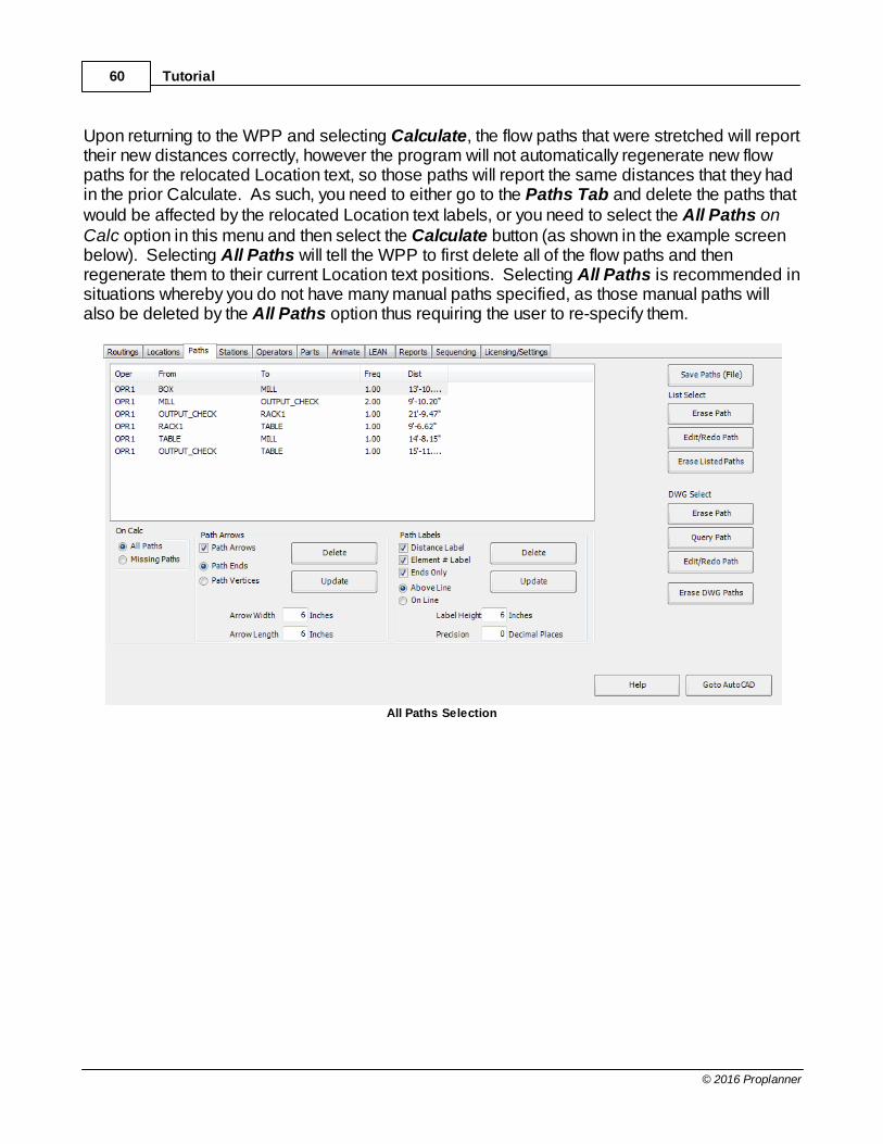
Upon returning to the WPP and selecting Calculate, the flow paths that were stretched will reporttheir new distances correctly, however the program will not automatically regenerate new flowpaths for the relocated Location text, so those paths will report the same distances that they hadin the prior Calculate. As such, you need to either go to the Paths Tab and delete the paths thatwould be affected by the relocated Location text labels, or you need to select the All Paths onCalc option in this menu and then select the Calculate button (as shown in the example screenbelow). Selecting All Paths will tell the WPP to first delete all of the flow paths and thenregenerate them to their current Location text positions. Selecting All Paths is recommended insituations whereby you do not have many manual paths specified, as those manual paths willalso be deleted by the All Paths option thus requiring the user to re-specify them.
All Paths Selection

Stationary Part Analysis 61
© 2016 Proplanner
Step 15: The output abilities of the WPP can be seen in the summary results window in thebottom left side of the routings window, the Lean chart on the LEAN tab, and the reports createdon the Reports tab.
The Lean chart is automatically created for the stationary example and will have differentamounts of Value and Walking depending on the speeds and distances that are set.
LEAN Chart Summary Results
The Station Report can be created on the Reports tab by selecting get image, setting yourstations takt time, and clicking Generate Report. The Station Report output can be exporteddirectly to Excel, saved, or printed.
Congratulations!! You have now completed the first tutorial on using the Proplanner WorkplacePlanner for stationary parts. You may now continue on to the next tutorial on using the WPP formoving parts, or you may wish to continue on to the WPP Manual.pdf for more detailedinformation on the WPP options.
Special Note: Your analysis summary will appear in the lower left corner of the routings screen. You may right-click in this window to copy these results to the clipboard. In fact, you can right-click and copy all WPP display list window information for subsequent pasting into otherwindows applications, such as MS Word or MS Excel.

Tutorial62
© 2016 Proplanner
6.2 Moving Part Analysis
STEP 1: To get started, make sure all other drawings in AutoCAD are closed. If you havealready been working in Workplace Planner, click the New (Clear) button in the Routings tab. Then Open the file WALKPATH-FCAD.DWG for Metric tutorials or WPP_Moving.DWG forFootInch, just as you did in the first Tutorial.
If you are already in AutoCAD you need not leave and reload AutoCAD, however, you will alsoneed to go to the Routings tab and select the Goto AutoCAD button as shown below.
STEP 2: You should now be in the AutoCAD screen and will be looking at the 2D or 3D staticworkplace layout. To view the moving part (dynamic) workplace layout select the view icon, ortype in the VIEW command in the command line, and double-click on the DYNAMIC-2D optionand select OK.
Dynamic-2D Option Drawing

Moving Part Analysis 63
© 2016 Proplanner
If your layout drawing looks like the top view of a 3D drawing (solid filled boxes) instead of wire-frame outlines, as shown above, then you need to select the 2-D wire-frame view of the layout. To do this select the 2D Wireframe icon located in the top right corner of the AutoCAD, or withinthe view tab dropdown depending on your AutoCAD version. If you could not find the 2DWireframe icon, please right click at the blank space on the toolbar, choose from the popupmenu "ACAD => Shade" or "ACAD=>View Style" depending on your AutoCAD version.
2D Wireframe
STEP 3: Once your view is correct, you will want to go into the WPP application. Dependingupon how you are starting this tutorial do the following
· New into AutoCAD: Perform step 2 in the first Tutorial.· From Goto AutoCAD in WPP: Select the Return to Workplace Planner button from
the WPP modeless window located in the top left corner of the screen.
Tutorial64
© 2016 Proplanner
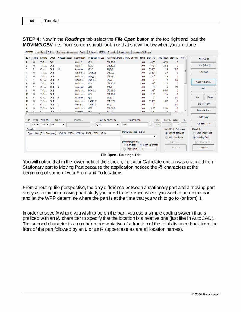
STEP 4: Now in the Routings tab select the File Open button at the top right and load theMOVING.CSV file. Your screen should look like that shown below when you are done.
File Open - Routings Tab
You will notice that in the lower right of the screen, that your Calculate option was changed fromStationary part to Moving Part because the application noticed the @ characters at thebeginning of some of your From and To locations.
From a routing file perspective, the only difference between a stationary part and a moving partanalysis is that in a moving part study you need to reference where you want to be on the partand let the WPP determine where the part is at the time that you wish to go to (or from) it.
In order to specify where you wish to be on the part, you use a simple coding system that isprefixed with an @ character to specify that the location is a relative one (just like in AutoCAD). The second character is a number representative of a fraction of the total distance back from thefront of the part followed by an L or an R (uppercase as are all location names).
Moving Part Analysis 65
© 2016 Proplanner
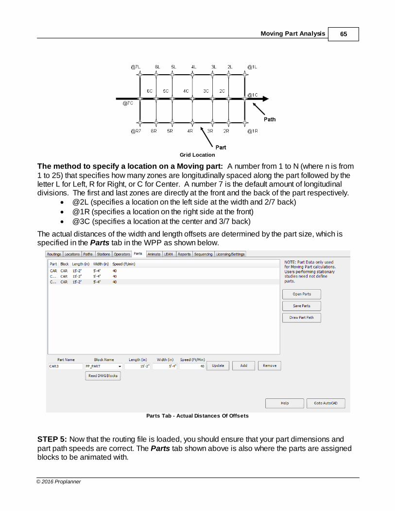
Grid Location
The method to specify a location on a Moving part: A number from 1 to N (where n is from1 to 25) that specifies how many zones are longitudinally spaced along the part followed by theletter L for Left, R for Right, or C for Center. A number 7 is the default amount of longitudinaldivisions. The first and last zones are directly at the front and the back of the part respectively.
· @2L (specifies a location on the left side at the width and 2/7 back)· @1R (specifies a location on the right side at the front)· @3C (specifies a location at the center and 3/7 back)
The actual distances of the width and length offsets are determined by the part size, which isspecified in the Parts tab in the WPP as shown below.
Parts Tab - Actual Distances Of Offsets
STEP 5: Now that the routing file is loaded, you should ensure that your part dimensions andpart path speeds are correct. The Parts tab shown above is also where the parts are assignedblocks to be animated with.
Tutorial66
© 2016 Proplanner
For the Foot-Inch example, a part speed of 40 feet/minute and a part length and width of 15’-2” (or 182 inches) and 5’-4” (or 64) inches has been used. When entering feet, do not forget toinclude the single-quote after the number or the program will assume that your input is beingspecified in Inches.
You may also wish to select the Operators tab to verify that the default operator speed is whatyou want. The WPP sets Operator walking speeds to 4.17’ per second which is an industrystandard used in MTM time studies. Another option on this tab is to set a max distance that theoperator can travel into a previous station to reach the part. If the part size is too big, theoperator may still go further than the limit so part length should be taken into consideration whensetting this number or the length of the part path.

Moving Part Analysis 67
© 2016 Proplanner
STEP 6: The Calculation is nearly ready to be ran. The only step left is to define the stationdimensions on the Stations tab shown below. Name the station, select what distance on the partpath the station begins, and how long the station is. Hit the add button to add the station or theupdate button to save changes and now you’re ready to do a Calculate. In this example, thecorrect station information should have be present, if not, enter 40' as the length.
Stations Tab - Dimensions

Tutorial68
© 2016 Proplanner
Now you can return to the Routings tab and simply select the Calculate button at the lower rightof the window. You will see the results shown in the Results Window (lower left of window) andDrawing - see examples below (actual results will vary slightly from these examples due tochanges in the individual sample files).
Results
Drawing
You will notice that in this example, you have two different operators and their flow paths areshown in different colors.
To generate this diagram, the WPP computed the speed of the vehicle, and the speed of theoperator walking. The WPP then took into account the process times at the vehicle and at thecontainers and racks along the line. The WPP then computed all of the line part/operatorintersection locations, created labels for these locations along the part path (white textperpendicular to part path), and generated the flow lines accordingly with path labels and flowarrows.
Moving Part Analysis 69
© 2016 Proplanner
STEP 7: Once you have completed the analysis you can select the Parts tab to make sure thatthe part block is set to CAR, Operator tab to make sure the operator is set to 3OPSDFEM, andthen proceed to the Animate tab to perform the following step.
STEP 8: Now on the Animate tab select the Animate button in the bottom right of the screenand watch the operators at work. You will notice that when the operators are working on the car,they travel at the speed of the car, but when the walk around the workplace, they travel at theirwalking speeds (which are faster – and must be – than that of the car).
Step 9: Finally, (and once the animation is complete, but before selecting the Return toWalkPath button) you will need to select the view icon or type in the VIEW command to see theanimation in 3D [if using FCAD DWG]. Now double-click on the DYNAMIC-3D option andselect OK.
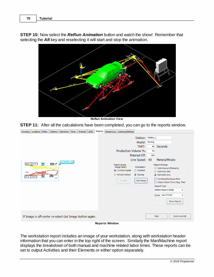
Tutorial70
© 2016 Proplanner
STEP 10: Now select the ReRun Animation button and watch the show! Remember thatselecting the Alt key and reselecting it will start and stop the animation.
ReRun Animation View
STEP 11: After all the calculations have been completed, you can go to the reports window.
Reports Window
The workstation report includes an image of your workstation, along with workstation headerinformation that you can enter in the top right of the screen. Similarly the Man/Machine reportdisplays the breakdown of both manual and machine related labor times. These reports can beset to output Activities and their Elements or either option separately.

Moving Part Analysis 71
© 2016 Proplanner
Select the Get Image button to get the current view of your workplace. You may need to selectthe Goto AutoCAD button in order to adjust your display such that the workstation view lookscorrect. You can also get image from a window. For best results getting image by a selectedwindow hit “Get Image” twice.
Once your view is acceptable; select the Station Report button to generate your report. Thisreport can also be made to show VA/NVA percentages by checking the checkbox. Once thereport is generated, simply select the File Save option in the browser window to save yourreport.

Tutorial72
© 2016 Proplanner
6.3 Stationary Part Analysis Metric
This tutorial was developed with the drawing units set to millimeters and the reporting units set tometers. In addition, the files have been saved in a semi-colon (;) delimited format with numbersspecified in the format (1.200,15) which is common in France, Germany, Italy, Sweden and othercountries. Before starting the tutorial, it is advised that you go to the "Licensing Settings" taband ensure that your settings are set as shown below.
Licensing Settings
STEP 1: To get started, make sure all other drawings in AutoCAD are closed. If you havealready been working in Workplace Planner, click the New (Clear) button in the Routings tab.Then Open the file “WALKPATH-2D.DWG” (make certain that you use only the tutorial files fromthe metric-semicolon directory). You should be able to see the Proplanner Applications menu onyour screen. If not, you will need to load this menu using the Menu Installation Guide included inthe Install.pdf.
STEP 2: If Workplace Planner is not already open, select the “W” icon button in the Proplannerribbon.
STEP 3: To import an existing workplace routing file, select the File Open button from the topright corner of the Routings tab screen as shown below. Then select the STATIONARY.CSVfile provided with the WPP application.
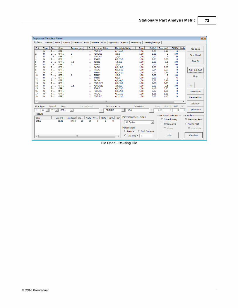
Stationary Part Analysis Metric 73
© 2016 Proplanner
File Open - Routing File

Tutorial74
© 2016 Proplanner
STEP 4: You should now be able to select the Calculate button (bottom right of the screen) toanalyze the initial workplace layout. The results of this Calculate can be seen in the Distanceand Time columns in the right side of the routings window and in the Results Area in the bottomleft corner. In addition, the flow lines should have been drawn in your layout as shown below.
Workplace Layout & Results
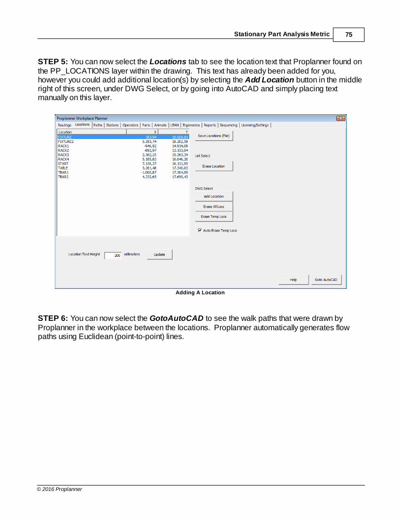
Stationary Part Analysis Metric 75
© 2016 Proplanner
STEP 5: You can now select the Locations tab to see the location text that Proplanner found onthe PP_LOCATIONS layer within the drawing. This text has already been added for you,however you could add additional location(s) by selecting the Add Location button in the middleright of this screen, under DWG Select, or by going into AutoCAD and simply placing textmanually on this layer.
Adding A Location
STEP 6: You can now select the GotoAutoCAD to see the walk paths that were drawn byProplanner in the workplace between the locations. Proplanner automatically generates flowpaths using Euclidean (point-to-point) lines.

Tutorial76
© 2016 Proplanner
STEP 7: One of the flow paths currently moves through a table. To replace this straight line flowpath with one that moves around the table select the Edit/Redo Path button in the DWG Selectsection of the Paths Tab (shown below in red oval).
Edit/Redo Path

Stationary Part Analysis Metric 77
© 2016 Proplanner
STEP 8: The WPP window will now disappear and you will be in the AutoCAD applicationwindow. AutoCAD is prompting you to select a path to replace with a new manually drawn one. Select the path in the top middle as indicated by the white arrow below.
Selecting A Path

Tutorial78
© 2016 Proplanner
STEP 9: The original path will now disappear and you will be prompted to enter a path fromSTART to FIXTURE. Simply pick points starting from where the path originated around the tableand then finally to the FIXTURE as shown below. When you pick your last point at the fixture youcan press Enter on the keyboard, or your Right mouse button. A WPP Alert window will showup. Click “OK”. You will then be returned to the Paths tab in the WPP application.
WPP Alert
You can do this again for the line from TBAR2 to the FIXTURE. When complete, you drawingshould now look as shown below.
Drawing
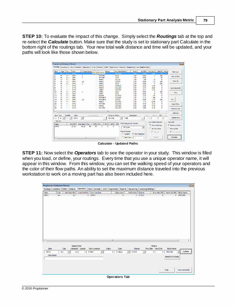
Stationary Part Analysis Metric 79
© 2016 Proplanner
STEP 10: To evaluate the impact of this change. Simply select the Routings tab at the top andre-select the Calculate button. Make sure that the study is set to stationary part Calculate in thebottom right of the routings tab. Your new total walk distance and time will be updated, and yourpaths will look like those shown below.
Calculate - Updated Paths
STEP 11: Now select the Operators tab to see the operator in your study. This window is filledwhen you load, or define, your routings. Every time that you use a unique operator name, it willappear in this window. From this window, you can set the walking speed of your operators andthe color of their flow paths. An ability to set the maximum distance traveled into the previousworkstation to work on a moving part has also been included here.
Operators Tab

Tutorial80
© 2016 Proplanner
STEP 12: Select the Operators tab and select the Person Block name of “PERSON” in the pull-down box (shown above). Next, select the Animate tab, and set the animation options (seebelow). Finally select the Animate button in the bottom right corner to watch the operatorperform the work in 2D.
Person Block Name
When the animation finishes, you will see the screen shown below with the total animation timedisplayed (Note: this time is dependent on your simulation Move Increment value specified inthe Animate tab window and thus may not agree exactly with the final results). Decreasing themove increment will increase the accuracy of your results and will slow down your animation. You can also slow down the animation by entering a delay factor in the Motion Delay input box.
Animation Window
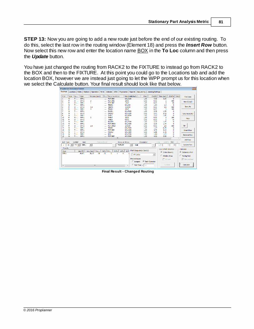
Stationary Part Analysis Metric 81
© 2016 Proplanner
STEP 13: Now you are going to add a new route just before the end of our existing routing. Todo this, select the last row in the routing window (Element 18) and press the Insert Row button. Now select this new row and enter the location name BOX in the To Loc column and then pressthe Update button.
You have just changed the routing from RACK2 to the FIXTURE to instead go from RACK2 tothe BOX and then to the FIXTURE. At this point you could go to the Locations tab and add thelocation BOX, however we are instead just going to let the WPP prompt us for this location whenwe select the Calculate button. Your final result should look like that below.
Final Result - Changed Routing
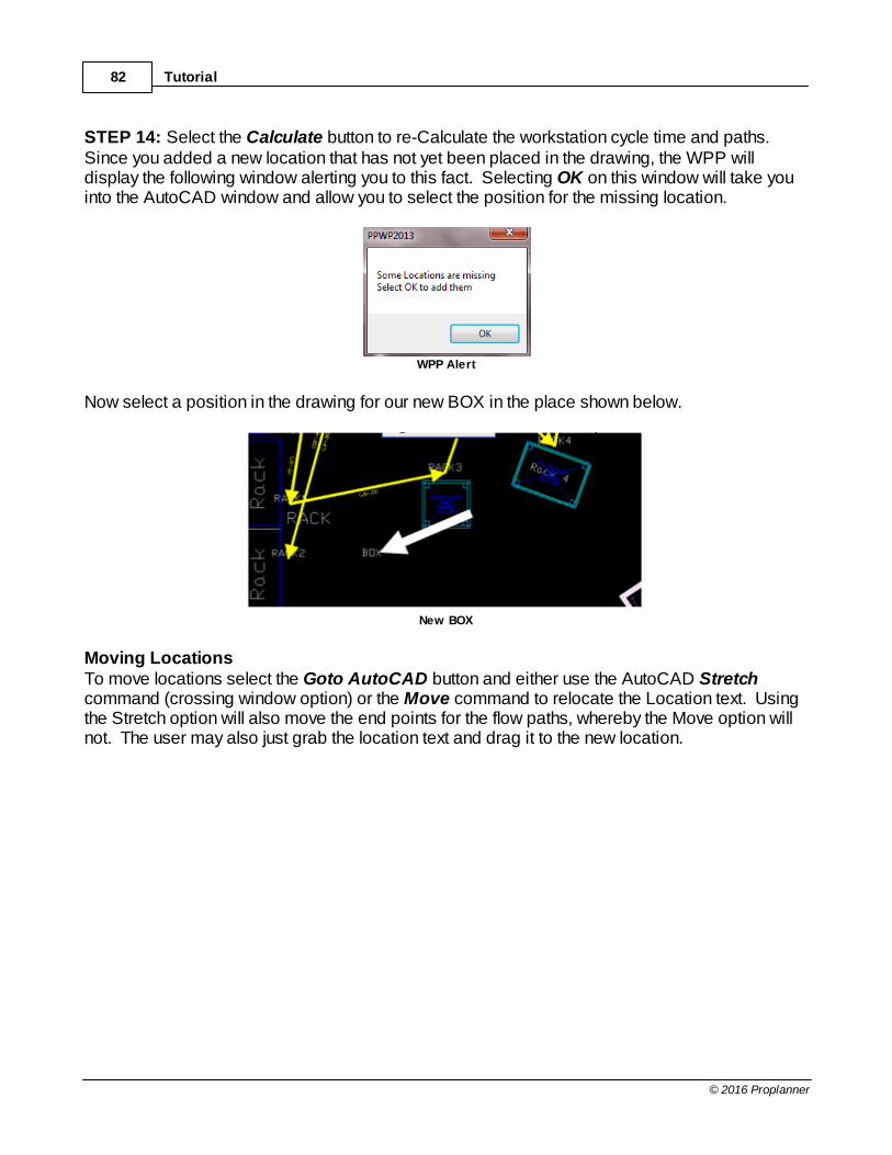
Tutorial82
© 2016 Proplanner
STEP 14: Select the Calculate button to re-Calculate the workstation cycle time and paths. Since you added a new location that has not yet been placed in the drawing, the WPP willdisplay the following window alerting you to this fact. Selecting OK on this window will take youinto the AutoCAD window and allow you to select the position for the missing location.
WPP Alert
Now select a position in the drawing for our new BOX in the place shown below.
New BOX
Moving LocationsTo move locations select the Goto AutoCAD button and either use the AutoCAD Stretchcommand (crossing window option) or the Move command to relocate the Location text. Usingthe Stretch option will also move the end points for the flow paths, whereby the Move option willnot. The user may also just grab the location text and drag it to the new location.

Stationary Part Analysis Metric 83
© 2016 Proplanner
Upon returning to the WPP and selecting Calculate, the flow paths that were stretched will reporttheir new distances correctly, however the program will not automatically regenerate new flowpaths for the relocated Location text, so those paths will report the same distances that they hadin the prior Calculate. As such, you need to either go to the Paths Tab and delete the paths thatwould be affected by the relocated Location text labels, or you need to select the All Paths onCalc option in this menu and then select the Calculate button (as shown in the example screenbelow). Selecting All Paths will tell the WPP to first delete all of the flow paths and thenregenerate them to their current Location text positions. Selecting All Paths is recommended insituations whereby you do not have many manual paths specified, as those manual paths willalso be deleted by the All Paths option thus requiring the user to re-specify them.
All Paths Selection
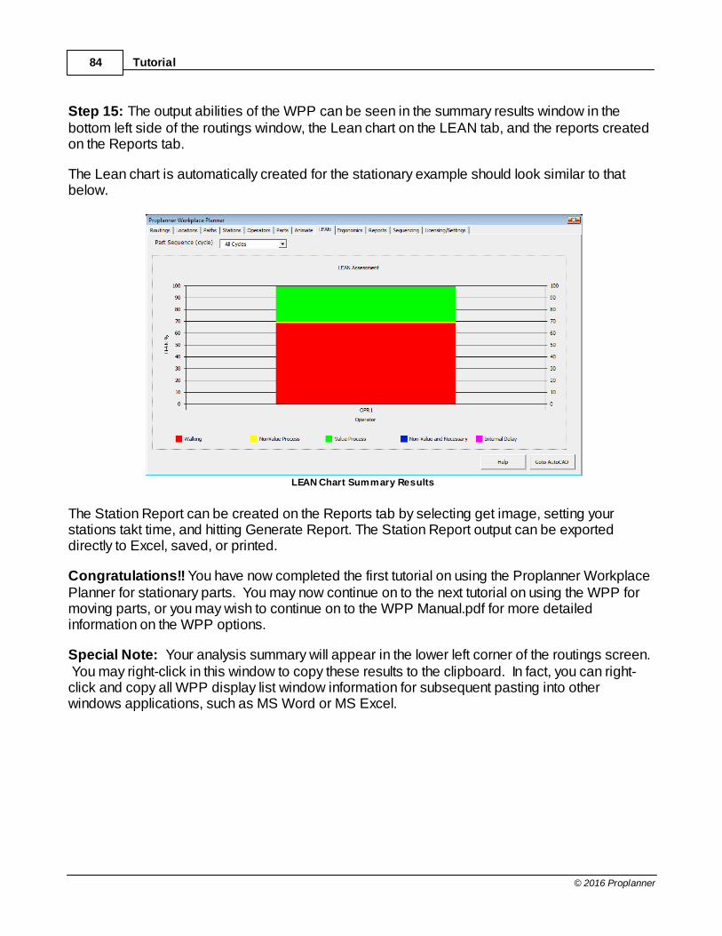
Tutorial84
© 2016 Proplanner
Step 15: The output abilities of the WPP can be seen in the summary results window in thebottom left side of the routings window, the Lean chart on the LEAN tab, and the reports createdon the Reports tab.
The Lean chart is automatically created for the stationary example should look similar to thatbelow.
LEAN Chart Summary Results
The Station Report can be created on the Reports tab by selecting get image, setting yourstations takt time, and hitting Generate Report. The Station Report output can be exporteddirectly to Excel, saved, or printed.
Congratulations!! You have now completed the first tutorial on using the Proplanner WorkplacePlanner for stationary parts. You may now continue on to the next tutorial on using the WPP formoving parts, or you may wish to continue on to the WPP Manual.pdf for more detailedinformation on the WPP options.
Special Note: Your analysis summary will appear in the lower left corner of the routings screen. You may right-click in this window to copy these results to the clipboard. In fact, you can right-click and copy all WPP display list window information for subsequent pasting into otherwindows applications, such as MS Word or MS Excel.

Stationary Part Analysis Metric 85
© 2016 Proplanner
6.4 Moving Part Analysis MetricThis tutorial was developed with the drawing units set to millimeters and the reporting units set tometers. In addition, the files have been saved in a semi-colon (;) delimited format with numbersspecified in the format (1.200,15) which is common in France, Germany, Italy, Sweden and othercountries. Before starting the tutorial, it is advised that you go to the "Licensing Settings" taband ensure that your settings are set as shown below.
Licensing Settings

Tutorial86
© 2016 Proplanner
STEP 1: To get started, make sure all other drawings in AutoCAD are closed. If you havealready been working in Workplace Planner, click the New (Clear) button in the Routings tab. Then Open the file WALKPATH-FCAD.DWG, just as you did in the first Tutorial.
If you are already in AutoCAD you need not leave and reload AutoCAD, however, you willneed to go to the Routings tab and select the Goto AutoCAD button as shown below.
STEP 2: You should now be in the AutoCAD screen and will be looking at the 2D or 3D staticworkplace layout. To view the moving part (dynamic) workplace layout select the view icon, ortype in the VIEW command just as you did in Step 15 of the first tutorial, and double-click on theDYNAMIC-2D option and select OK.
Dynamic-2D View

Moving Part Analysis Metric 87
© 2016 Proplanner
If your layout drawing looks like the top view of a 3D drawing (solid filled boxes) instead of wire-frame outlines, as shown above, then you need to select the 2-D wire-frame view of the layout. To do this select the 2D Wireframe icon located in the top right corner of the AutoCAD windowas shown below (If you could not find the 2D Wireframe icon, please right click at the blankspace on the toolbar, choose from the popup menu "ACAD => Shade" or "ACAD=>View Style"depending on your AutoCAD version).
2D Wireframe
STEP 3: Once your view is correct, you will want to go into the WPP application. Dependingupon how you are starting this tutorial do the following
· New into AutoCAD: Perform steps 2, 3 and 4 in the first Tutorial.· From Goto AutoCAD in WPP: Select the Return to Walkplace Planner button from
the WPP modeless window located in the top left corner of the screen.
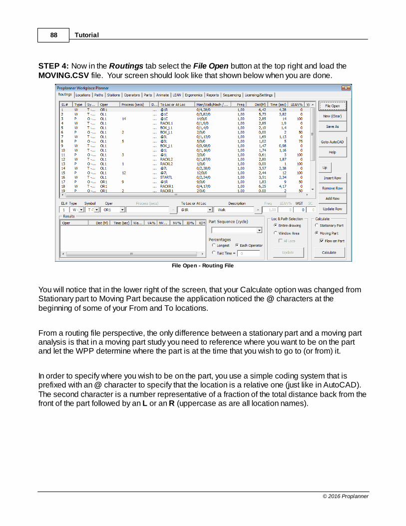
Tutorial88
© 2016 Proplanner
STEP 4: Now in the Routings tab select the File Open button at the top right and load theMOVING.CSV file. Your screen should look like that shown below when you are done.
File Open - Routing File
You will notice that in the lower right of the screen, that your Calculate option was changed fromStationary part to Moving Part because the application noticed the @ characters at thebeginning of some of your From and To locations.
From a routing file perspective, the only difference between a stationary part and a moving partanalysis is that in a moving part study you need to reference where you want to be on the partand let the WPP determine where the part is at the time that you wish to go to (or from) it.
In order to specify where you wish to be on the part, you use a simple coding system that isprefixed with an @ character to specify that the location is a relative one (just like in AutoCAD). The second character is a number representative of a fraction of the total distance back from thefront of the part followed by an L or an R (uppercase as are all location names).
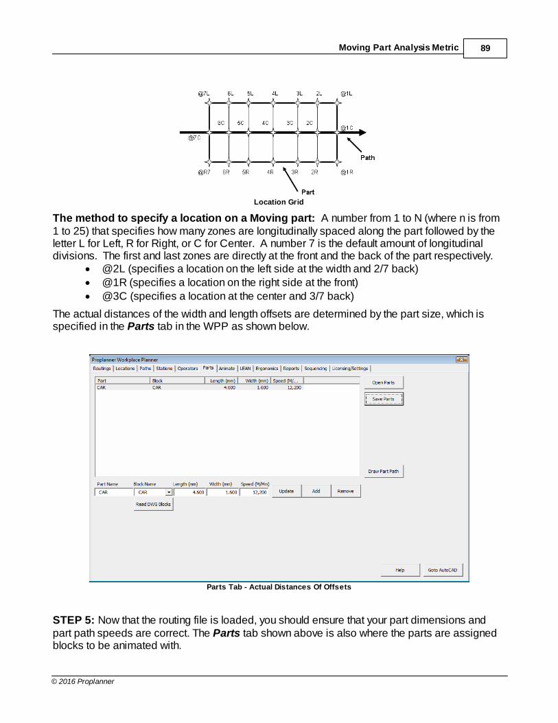
Moving Part Analysis Metric 89
© 2016 Proplanner
Location Grid
The method to specify a location on a Moving part: A number from 1 to N (where n is from1 to 25) that specifies how many zones are longitudinally spaced along the part followed by theletter L for Left, R for Right, or C for Center. A number 7 is the default amount of longitudinaldivisions. The first and last zones are directly at the front and the back of the part respectively.
· @2L (specifies a location on the left side at the width and 2/7 back)· @1R (specifies a location on the right side at the front)· @3C (specifies a location at the center and 3/7 back)
The actual distances of the width and length offsets are determined by the part size, which isspecified in the Parts tab in the WPP as shown below.
Parts Tab - Actual Distances Of Offsets
STEP 5: Now that the routing file is loaded, you should ensure that your part dimensions andpart path speeds are correct. The Parts tab shown above is also where the parts are assignedblocks to be animated with.

Tutorial90
© 2016 Proplanner
For the Foot-Inch example, a part speed of 12,2 meters/minute and a part length and width of 4,6meters and 1,6 meters has been used.

Moving Part Analysis Metric 91
© 2016 Proplanner
You may also wish to select the Operators tab to verify that the default operator speed is whatyou want. The WPP sets Operator walking speeds to 1,5 meters per second. Another option onthis tab is to set a max distance that the operator can travel into a previous station to reach thepart. If the part size is too big, the operator may still go further than the limit so part length shouldbe taken into consideration when setting this number or the length of the part path.
Operators Tab
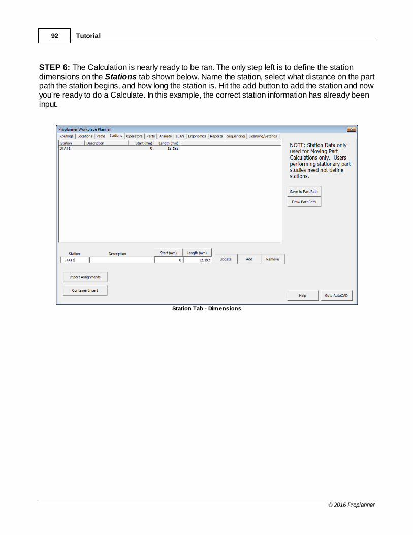
Tutorial92
© 2016 Proplanner
STEP 6: The Calculation is nearly ready to be ran. The only step left is to define the stationdimensions on the Stations tab shown below. Name the station, select what distance on the partpath the station begins, and how long the station is. Hit the add button to add the station and nowyou’re ready to do a Calculate. In this example, the correct station information has already beeninput.
Station Tab - Dimensions
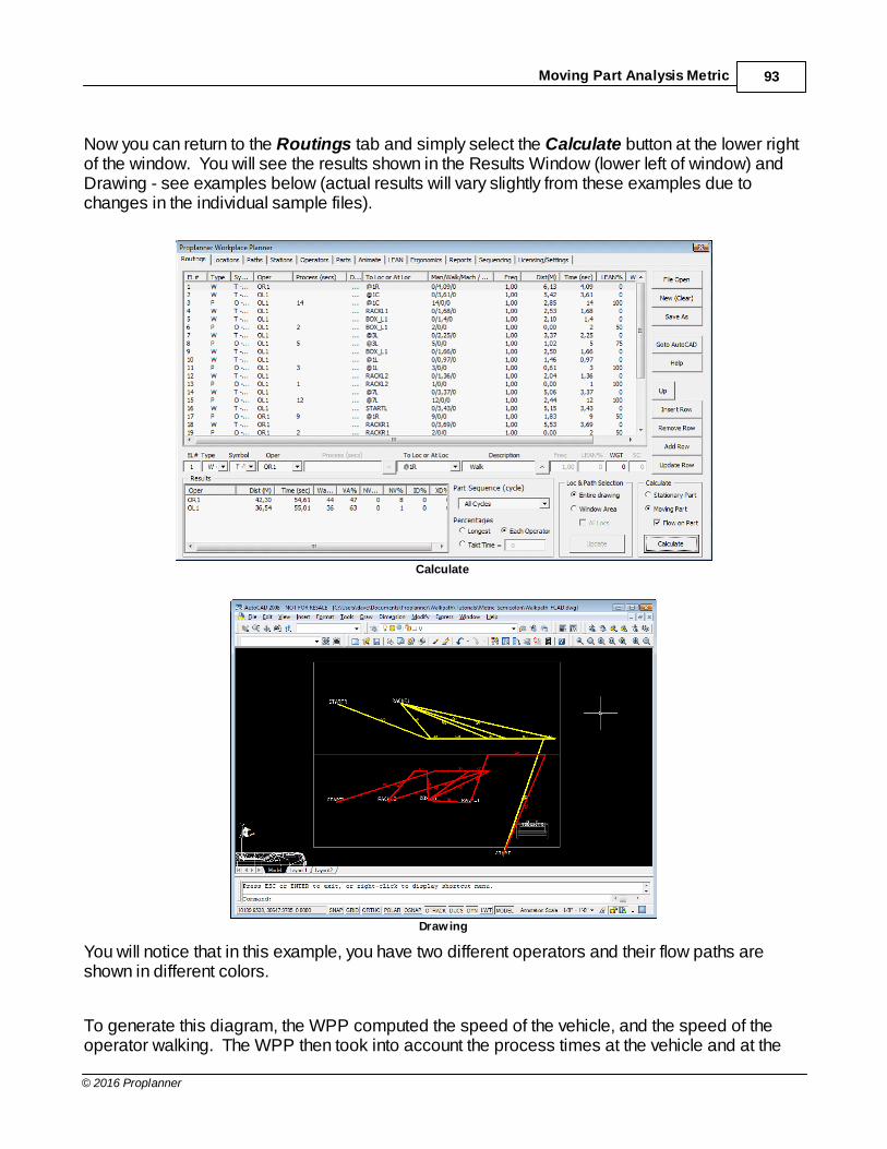
Moving Part Analysis Metric 93
© 2016 Proplanner
Now you can return to the Routings tab and simply select the Calculate button at the lower rightof the window. You will see the results shown in the Results Window (lower left of window) andDrawing - see examples below (actual results will vary slightly from these examples due tochanges in the individual sample files).
Calculate
Drawing
You will notice that in this example, you have two different operators and their flow paths areshown in different colors.
To generate this diagram, the WPP computed the speed of the vehicle, and the speed of theoperator walking. The WPP then took into account the process times at the vehicle and at the

Tutorial94
© 2016 Proplanner
containers and racks along the line. The WPP then computed all of the line part/operatorintersection locations, created labels for these locations along the part path (white textperpendicular to part path), and generated the flow lines accordingly with path labels and flowarrows.
STEP 7: Once you have completed the analysis you can select the Parts tab to make sure thatthe part block is set to CAR, Operator tab to make sure the operator is set to PERSON, andthen proceed to the Animate tab to perform the following step.
STEP 8: Now on the Animate tab select the Animate button in the bottom right of the screenand watch the operators at work. You will notice that when the operators are working on the car,they travel at the speed of the car, but when the walk around the workplace, they travel at theirwalking speeds (which are faster – and must be – than that of the car). For optimal animation,you will want to set your animation move increment to 0,1 seconds.
Step 9: Finally, (and once the animation is complete, but before selecting the Return toWalkPath button) you will need to select the view icon or type in the VIEW command to see theanimation in 3D [if using FCAD DWG]. Now double-click on the DYNAMIC-3D option andselect OK.
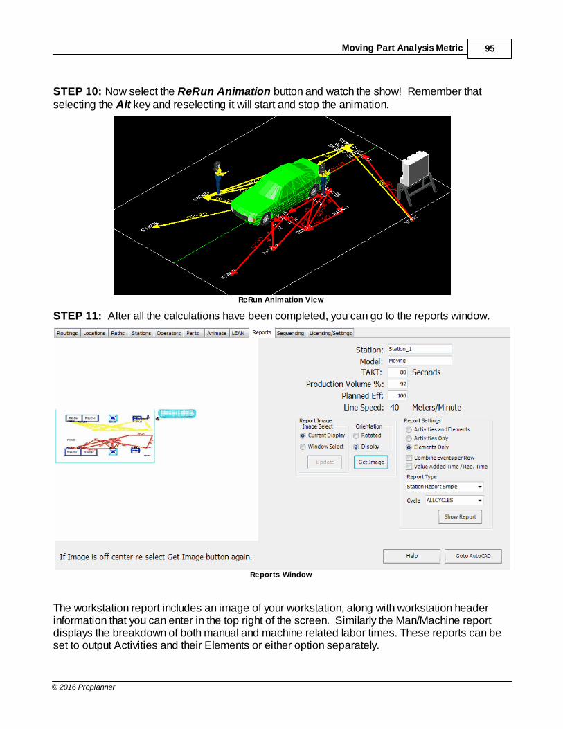
Moving Part Analysis Metric 95
© 2016 Proplanner
STEP 10: Now select the ReRun Animation button and watch the show! Remember thatselecting the Alt key and reselecting it will start and stop the animation.
ReRun Animation View
STEP 11: After all the calculations have been completed, you can go to the reports window.
Reports Window
The workstation report includes an image of your workstation, along with workstation headerinformation that you can enter in the top right of the screen. Similarly the Man/Machine reportdisplays the breakdown of both manual and machine related labor times. These reports can beset to output Activities and their Elements or either option separately.

Tutorial96
© 2016 Proplanner
Select the Get Image button to get the current view of your workplace. You may need to selectthe Goto AutoCAD button in order to adjust your display such that the workstation view lookscorrect. You can also get image from a window. For best results getting image by a selectedwindow hit “Get Image” twice.
Once your view is acceptable; select the Station Report button to generate your report. Thisreport can also be made to show VA/NVA percentages by checking the checkbox. Once thereport is generated, simply select the File Save option in the browser window to save yourreport.

Moving Part Analysis Metric 97
© 2016 Proplanner
6.5 Sequencing from Line Balance data MetricThis tutorial was developed with the drawing units set to millimeters and the reporting units set tometers. In addition, the files have been saved in a semi-colon (;) delimited format with numbersspecified in the format (1.200,15) which is common in France, Germany, Italy, Sweden and othercountries. Before starting the tutorial, it is advised that you go to the "Licensing Settings" taband ensure that your settings are set as shown below.
Licensing Settings
STEP 1: Now that you have learned how to run a part study from a pre-constructed routing file itis time to create one from data that has been output from Proplanner Line Balance. The first stepis to open the drawing file “Multi-Station Moving.dwg”. You will notice that this example hasmultiple stations and parts.
STEP 2: Start the Workplace Planner by clicking on the “W” in the menu bar and clickinganywhere on the splash screen that pops up. This will take you to the routings tab, the maininterface of the WPP.
STEP 3: Click on the “Sequencing” tab to start importing the Line Balance data and select“Open Scenario”.
STEP 4: Open the pre-made Line Balance scenario file “LBData.xml”. This can be found in thesame directory as the other example files, usually in “c:\Program Files\Proplanner\AutoCADPrograms”. For more information on making the Line Balance input file with Proplanner Line

Tutorial98
© 2016 Proplanner
Balance, sold separately, consult the Line Balance user manual.
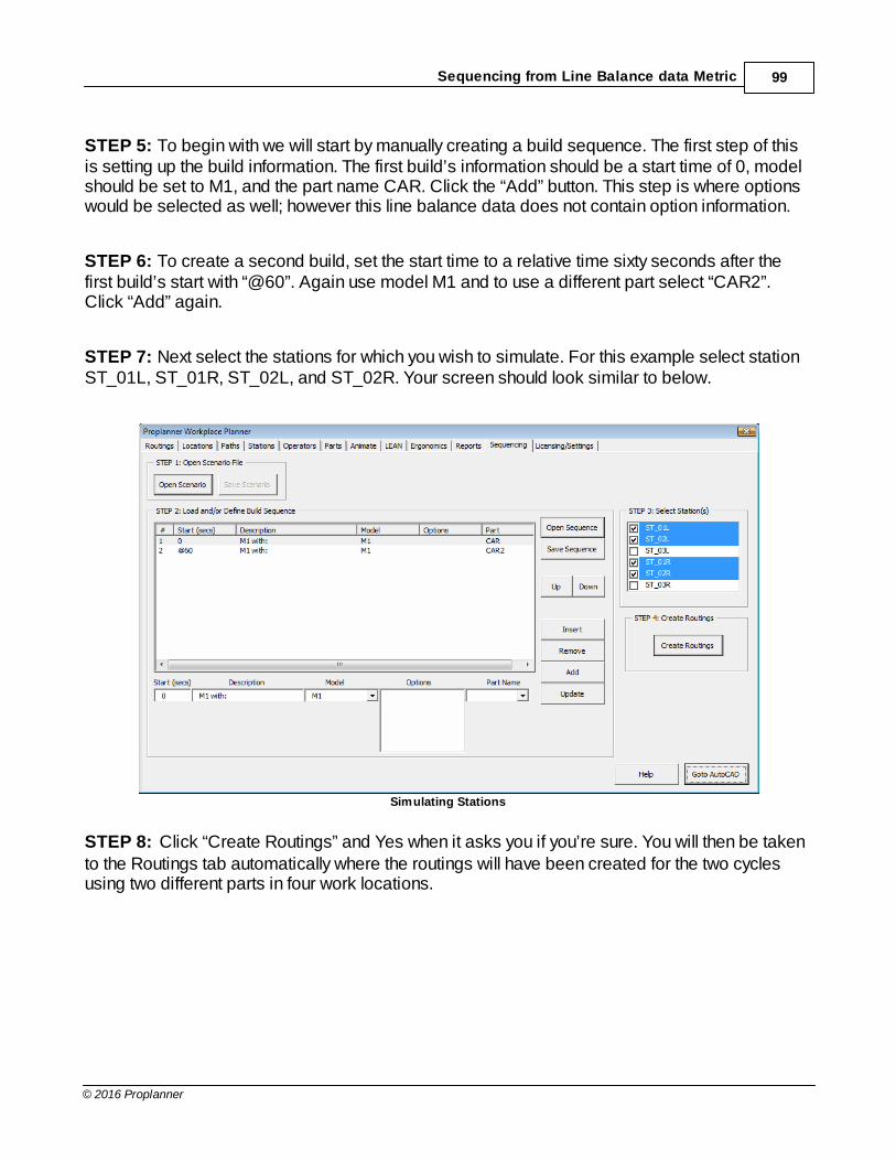
Sequencing from Line Balance data Metric 99
© 2016 Proplanner
STEP 5: To begin with we will start by manually creating a build sequence. The first step of thisis setting up the build information. The first build’s information should be a start time of 0, modelshould be set to M1, and the part name CAR. Click the “Add” button. This step is where optionswould be selected as well; however this line balance data does not contain option information.
STEP 6: To create a second build, set the start time to a relative time sixty seconds after thefirst build’s start with “@60”. Again use model M1 and to use a different part select “CAR2”.Click “Add” again.
STEP 7: Next select the stations for which you wish to simulate. For this example select stationST_01L, ST_01R, ST_02L, and ST_02R. Your screen should look similar to below.
Simulating Stations
STEP 8: Click “Create Routings” and Yes when it asks you if you’re sure. You will then be takento the Routings tab automatically where the routings will have been created for the two cyclesusing two different parts in four work locations.

Tutorial100
© 2016 Proplanner
STEP 9: Chose the Operators tab to make sure that your four operators have been created.Assign each operator to the station with their same name. They will be assigned to station Stat1and Stat2 at first. This is done by selecting the operator you wish to edit, selecting the stationpull-down menu, selecting the appropriate station and then selecting the “Update” button. Whencompleted it should look like the example below.
Operators Tab - Four Operators Assigned

Sequencing from Line Balance data Metric 101
© 2016 Proplanner
STEP 10: Go to the Stations tab and make sure that the stations used are defined correctly. TheST_01L and ST_01R stations should start at the 0 distance along the part path and have adistance of 12,2 meters. The ST_02L and ST_02R stations should have a start at the 12,2 meterand be an additional 12,2 meters long. Because the input is in millimeters, this will be in put as12.200. Your Station information should look like that below.
Stations Defined Correctly
Because stat1 and stat2 were unassigned from the operators remove them at this point.
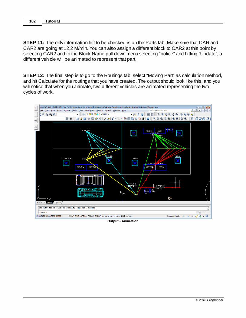
Tutorial102
© 2016 Proplanner
STEP 11: The only information left to be checked is on the Parts tab. Make sure that CAR andCAR2 are going at 12,2 M/min. You can also assign a different block to CAR2 at this point byselecting CAR2 and in the Block Name pull-down menu selecting “police” and hitting “Update”, adifferent vehicle will be animated to represent that part.
STEP 12: The final step is to go to the Routings tab, select “Moving Part” as calculation method,and hit Calculate for the routings that you have created. The output should look like this, and youwill notice that when you animate, two different vehicles are animated representing the twocycles of work.
Output - Animation

Sequencing from Line Balance data Metric 103
© 2016 Proplanner
STEP 13: Returning to the Workplace Planner and selecting the Sequencing tab again will allowyou to save the created build sequence or upload a pre-existing one. Selecting “OpenSequence” will allow you to open LBData_Seq.xml which is the same as the sequence you justsimulated. If you create routings and Calculate, the results should be the same.
STEP 14: To see the results Calculated there are three main places for this. First of all the roughsummary output can be seen in the bottom left side of the routings tab shown below. The resultsare boxed in red.
Rough Summary Output & Results
The blue box highlights the pull down window that selects which cycle to show results for, whetherall or individual part cycles. Below that are radio buttons that select how the output percentagesare Calculated. This can be set to be a percentage of the longest operator’s time, eachindividual operator’s time, or as a percentage of a set TAKT time.

Tutorial104
© 2016 Proplanner
The second output tool of the WPP is the LEAN tab which automatically creates a bar chartdepicting the percentages of time performing value added, non-value added, non-value addedbut necessary, and delay times. This can be representative of all the cycles or an individualcycle, selected in the pull down window and should look like that below for the sequencingtutorial.
LEAN Tab
The final and most comprehensive output is the report generated on the Reports tab. These aregenerated by selecting get image to take a picture of the current screen, setting a station takttime, selecting which cycle or all to show results for and pushing the Generate Report button.Selecting a sequence to report for is done in the pull down window. The report generated shouldlook similar to the one below.
Reports Tab - Report Output

Sequencing from Line Balance data Metric 105
© 2016 Proplanner
7 Exercise
Plant wide material flow analysis
The objective of this exercise will be to use the techniques learned in the Tutorial, along with theaid of the How To Guide and Sample WPP Input (in Proplanner fold \Help Files\PPWPP_Exercise_Samples), to take a simple set of workplace and operator data and perform acomplete Workplace Planner analysis.
Exercise One: Format a data set for importing to the Workplace Planner
Use this Excel spreadsheet (in Proplanner fold \Help Files\PPWPP_Exercise_Samples\WPP1.xls) ofstation and operator data along with the Sample WPP Input to create a CSV file to import intothe WPP.
1. To do this extract the data and format it similar to the sample input.
2. Include only the necessary information outlined in the sample input file. It will need picked out ofthe original spreadsheet and re-organized.
3.Make sure there are no special characters in the CSV data by opening it in notepad. Also removeany superfluous commas at the end of the element lines. The Sample WPP Input has more detailson this. Most common errors include spaces and quotation marks.
4.Once the data is set up correctly open the WPP within AutoCAD and try opening the CSV. Ifdone correctly the files will open flawlessly.
5. If the files cause an error, consult your instructor or the Troubleshooting Guide.
Results – Workplace Planner will open the files with no errors.
Exercise Two: Prepare layout drawing
1.Open “in Proplanner fold \Help Files\PPWPP_Exercise_Samples\WPP_Stationary_1.dwg” inAutoCAD. You may note that there is a person block placed in the drawing. Leave this there foruse when animating if you chose to do so at a later time.
2. Create layer PP_LOCATIONS by opening the WPP.
3. Insert the names of the locations using the Workplace Planner’s Add Location command. Thelocation names can be found in the CSV file.
4.Once this is done, open “in Proplanner fold \Help Files\PPWPP_Exercise_Samples\WPP2.csv” torun a stationary part calculation.
Results – Workplace Planner will not ask user to place locations when a calculation is run.

Exercise106
© 2016 Proplanner
Exercise Three: Perform a Stationary Part study
Using “in Proplanner fold \Help Files\PPWPP_Exercise_Samples\WPP_Stationary_2.dwg” instead ofthe drawing file just created, along with “in Proplanner fold \Help Files\PPWPP_Exercise_Samples\WPP2.csv” will ensure that we get the same results when this exercise is complete.
1.Open the drawing and notice that all the locations have been placed as in exercise two. Youmay note that there is a person block placed in the drawing. Leave this there for use whenanimating if you chose to do so at a later time.
2. Start the Workplace Planner and open the CSV mentioned above. It should be identical, for themost part, to the CSV file created in the first exercise.
3. Check the Routings tab to make sure all the data has been imported into the correct fields.
4.Go to the Licensing/Settings tab to ensure that the units are in feet and inches and that theoperator start location is set to Operator Start.
5. Return to the Routings tab and select the Stationary Part Calculation radio button. If this optionis set to moving, the calculation will not complete because that method needs a path for thepart to move on.
6. Run the calculation. A Stationary part study will now be drawn on the AutoCAD drawing.
7.Now that the calculation is complete, return to the Routings tab and look at the Results Windowin the lower left side of the WPP window.
Results – The results window should equal those below if the calculation has been run correctly.
Stationary Part Study Results
Exercise Four: Perform a Moving Part study
1.Open the drawing “in Proplanner fold \Help Files\PPWPP_Exercise_Samples\WPP_Moving.dwg”.You may note that there is a person and car block placed in the drawing. Leave this there foruse when animating if you chose to do so at a later time.
2. Start the Workplace Planner and open the CSV “in Proplanner fold \Help Files

107
© 2016 Proplanner
\PPWPP_Exercise_Samples\WPP3.csv”.
3. Check the Routings tab to make sure all the data has been imported into the correct fields.
4.Go to the Options tab to ensure that the units are in feet and inches and that the operator startlocation is set to Operator Start instead of first or last activity location.
5.On the Licensing/Settings tab set the part speed to 5 feet per minute.
6.Use the Draw Part Path button to go to AutoCAD and draw a horizontal line connecting themiddle of both vertical cell boundary lines, similar to the moving example in the Tutorial.
7.On the Operators tab assign the two operators their respective start locations of START_L andSTART_R.
8.Make sure they are assigned to station “stat1” on the operators tab and that the station “stat1”is defined with the start of 0 and length of 480” or 40’.
9. Return to the Routings tab and select the Moving Part Calculation radio button. If this option isset to stationary, the calculation will ask for all the on part or moving locations as staticlocations.
10.Run the calculation. A Moving part study will now be drawn on the AutoCAD drawing.
11.Now that the calculation is complete, return to the Routings tab and look at the ResultsWindow in the lower left side of the WPP window.
Results – The results window should equal those below if the calculation has been run correctly.
Moving Part Study Results
Exercise Five: Improving layout to reduce labor times
There are many different ways to improve our layouts. For now we will use the drawing, “inProplanner fold \Help Files\PPWPP_Exercise_Samples\WPP_Stationary_3.dwg” and “in Proplanner
fold \Help Files\PPWPP_Exercise_Samples\ WPP2.csv” so that we have a common set of output.
The most obvious ways of improving a layout may be to push locations closer together. Because inmany cases there are locations which cannot be moved, we assumed the racks and tables to bethe only mobile locations. To move the locations simply grab the text for the location and drag itto the new desired locations.
1.Open the drawing in AutoCAD and CSV within the WPP.

Exercise108
© 2016 Proplanner
2.Notice that the racks have been moved to reduce walk time and increase free space.
3. Run a Stationary calculation to see the results.
Results – You should see results similar to below. Notice the drop in time and walk percentage.
Stationary Calculation Results
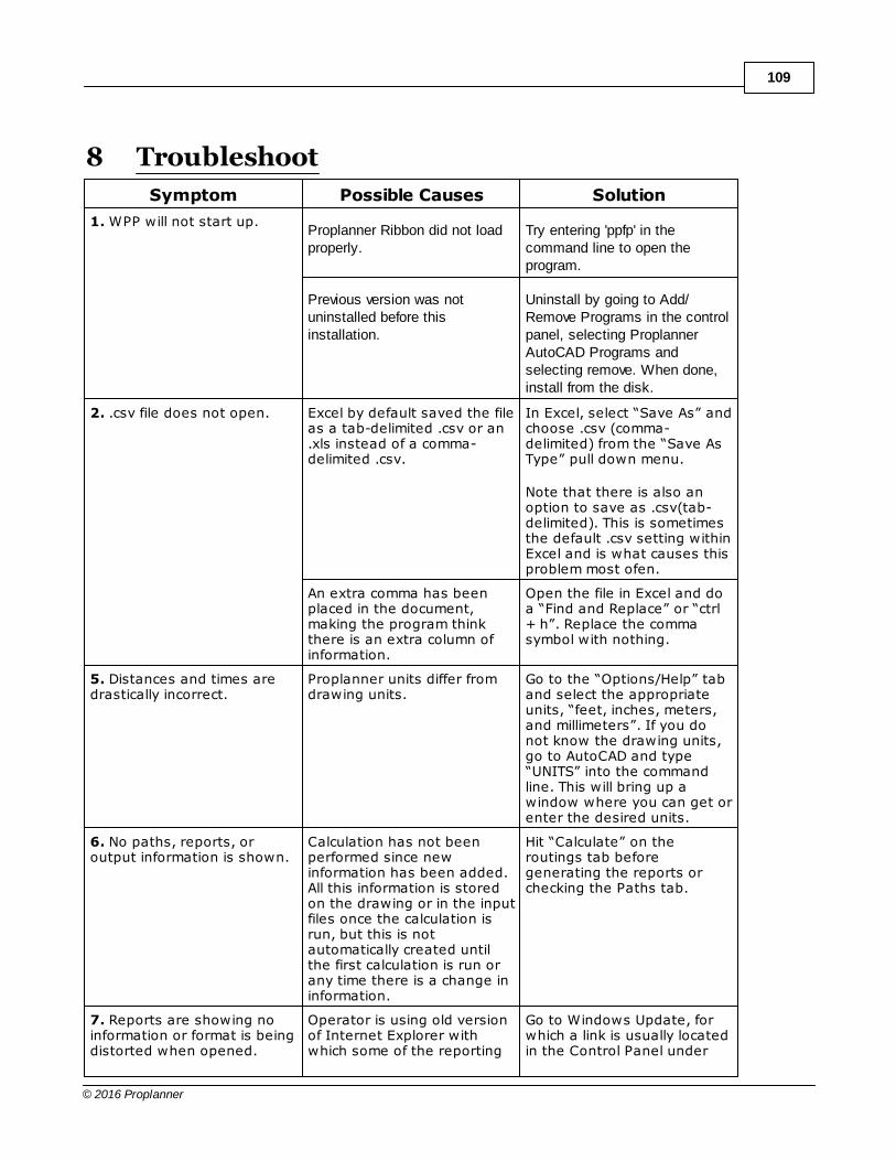
109
© 2016 Proplanner
8 Troubleshoot
Symptom Possible Causes Solution
1. WPP will not start up.Proplanner Ribbon did not loadproperly.
Try entering 'ppfp' in thecommand line to open theprogram.
Previous version was notuninstalled before thisinstallation.
Uninstall by going to Add/Remove Programs in the controlpanel, selecting ProplannerAutoCAD Programs andselecting remove. When done,install from the disk.
2. .csv file does not open. Excel by default saved the fileas a tab-delimited .csv or an.xls instead of a comma-delimited .csv.
In Excel, select “Save As” andchoose .csv (comma-delimited) from the “Save AsType” pull down menu.
Note that there is also anoption to save as .csv(tab-delimited). This is sometimesthe default .csv setting withinExcel and is what causes thisproblem most ofen.
An extra comma has beenplaced in the document,making the program thinkthere is an extra column ofinformation.
Open the file in Excel and doa “Find and Replace” or “ctrl+ h”. Replace the commasymbol with nothing.
5. Distances and times aredrastically incorrect.
Proplanner units differ fromdrawing units.
Go to the “Options/Help” taband select the appropriateunits, “feet, inches, meters,and millimeters”. If you donot know the drawing units,go to AutoCAD and type“UNITS” into the commandline. This will bring up awindow where you can get orenter the desired units.
6. No paths, reports, oroutput information is shown.
Calculation has not beenperformed since newinformation has been added.All this information is storedon the drawing or in the inputfiles once the calculation isrun, but this is notautomatically created untilthe first calculation is run orany time there is a change ininformation.
Hit “Calculate” on theroutings tab beforegenerating the reports orchecking the Paths tab.
7. Reports are showing noinformation or format is beingdistorted when opened.
Operator is using old versionof Internet Explorer withwhich some of the reporting
Go to Windows Update, forwhich a link is usually locatedin the Control Panel under

Troubleshoot110
© 2016 Proplanner
functions are not compatible. Settings and update to thelatest version.
8. When moving partcalculation is run it asks forthe “on part” locations asfixed locations.
Analysis type is set toStationary Part.
Change the radio button onthe Routings tab to MovingPart.
9. Part locations do not workcorrectly.
There are now two syntaxesfor entering the part location.The wrong one beingselected will cause an error.
On the Options/Help tabmake sure that the part gridformat is set to the r/l/w or l/c/r, whichever is the formatthe routings follow. Also thenumber of spots on the partis now default of 7 and set toletters up to D. This can bechanged to the desiredamount of divisions in the pulldown window to the right ofthe Part Grid box.
10. Path lines are either toosmall or too large.
These do not automaticallyscale so must be setmanually.
These can be set manually onthe Routings tab under PathThickness/Frequency. Thisthickness is scaled in thedrawing units.
11. Despite the operatorbeing limited to a setdistance it can go into theprevious station, it still walksfurther than that to reach theback of the moving part.
This is due to the length ofthe part/path.
This can be overcome byadding a delay to the processto let the part enter the workzone or shortening the partpath so that the worker doesnot start working on it untilthe entire part has movedwithin the work zone.
12. Simulation sends workerto other stations or to theorigin when doing a movingpart study.
There are duplicate partpaths or locations in thedrawing often caused bydrawings with multiplestations.
Select by Window Area onthe Routings tab and put abox around the workstationthe study is focusing on.
13. Frequency, line, andarrow thickness areincreasing every time acalculation is performed.
Operator name contains animproper character.
Operator names are onlyallowed to have letters,numbers, dashes, andunderscores. Remove anyother characters from theoperator name and hitupdate, on the operators tab.

111
© 2016 Proplanner
8.1 How To Guide
Workstation Labor Analysis
Base Steps:
1. Import plant drawing to AutoCAD.
Plant Drawing
2. Input routing information by using our route building system or using Excel to copy andpaste the larger quantities of information into the proper columns to be imported directly to WPP.
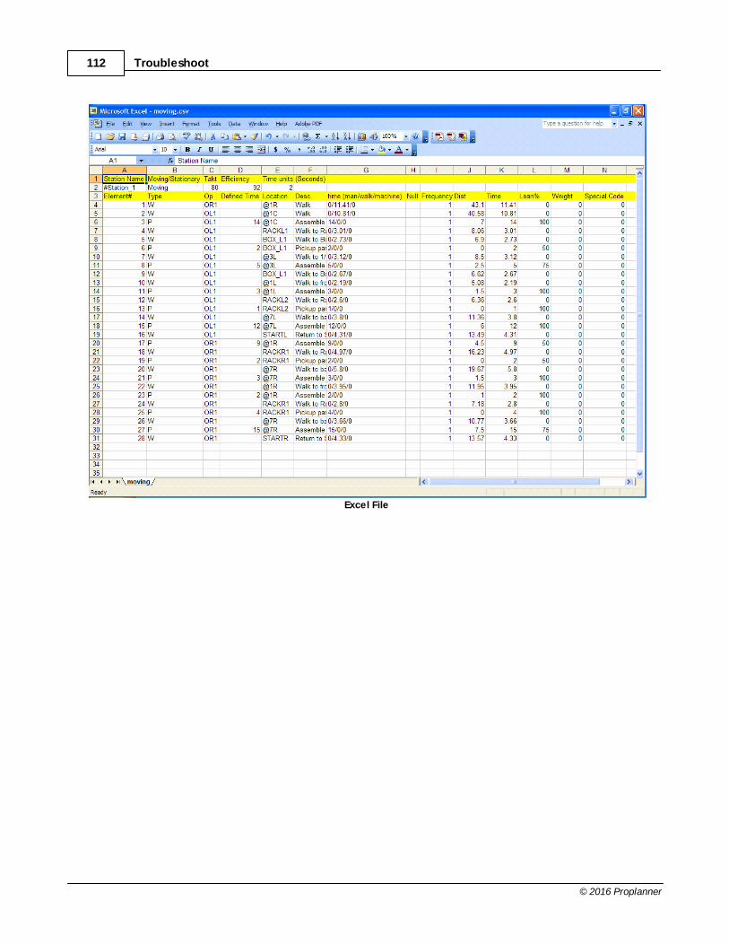
Troubleshoot112
© 2016 Proplanner
Excel File
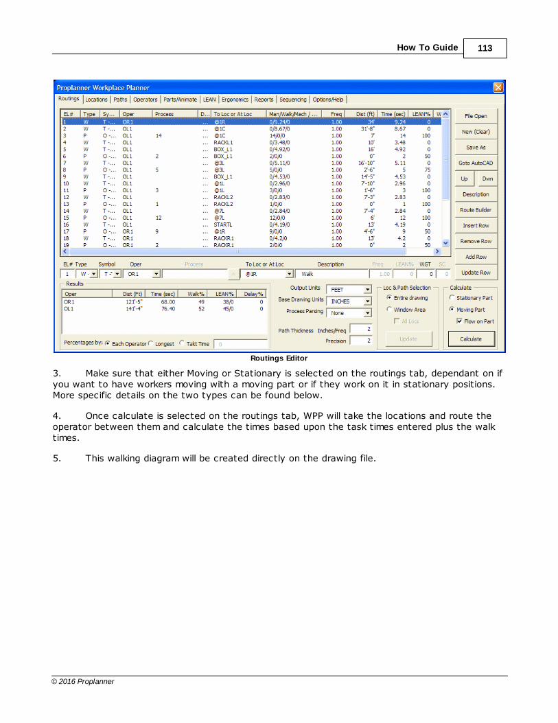
How To Guide 113
© 2016 Proplanner
Routings Editor
3. Make sure that either Moving or Stationary is selected on the routings tab, dependant on ifyou want to have workers moving with a moving part or if they work on it in stationary positions.More specific details on the two types can be found below.
4. Once calculate is selected on the routings tab, WPP will take the locations and route theoperator between them and calculate the times based upon the task times entered plus the walktimes.
5. This walking diagram will be created directly on the drawing file.

Troubleshoot114
© 2016 Proplanner
Walking Diagram
6. Observe summary results on the routings tab, path information, Lean information, orreported information.
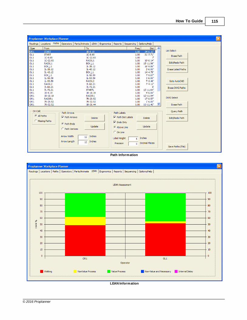
How To Guide 115
© 2016 Proplanner
Path Information
LEAN Information
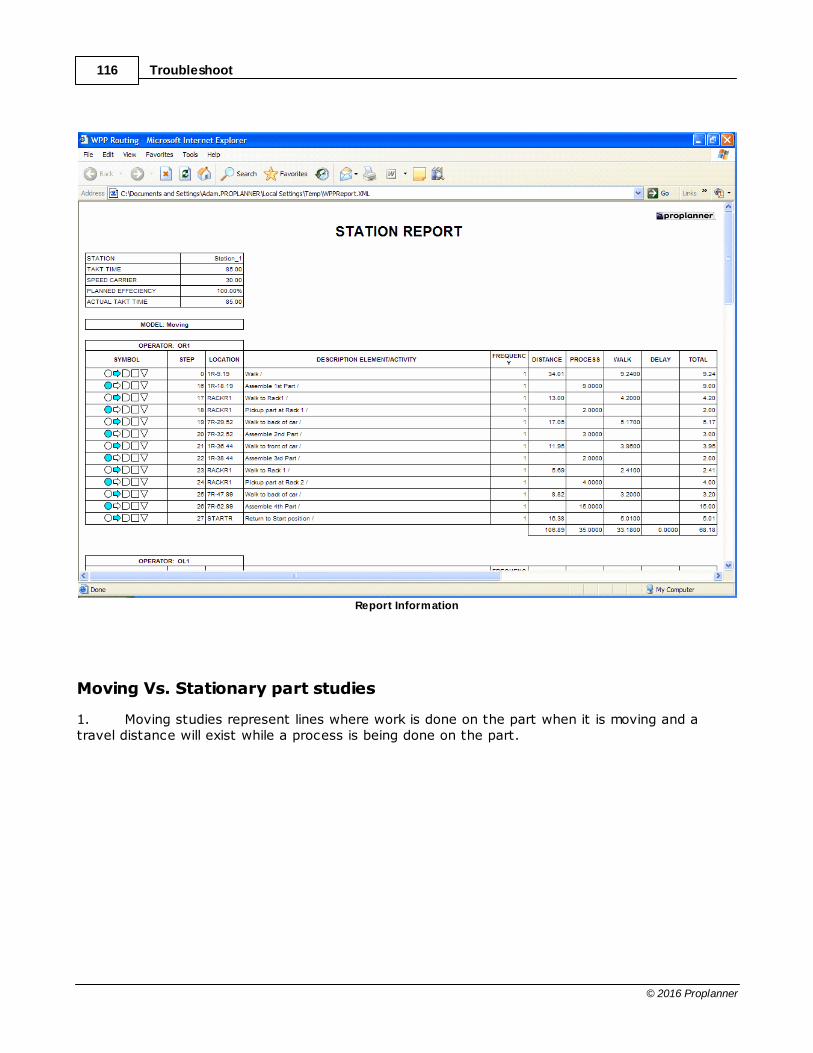
Troubleshoot116
© 2016 Proplanner
Report Information
Moving Vs. Stationary part studies
1. Moving studies represent lines where work is done on the part when it is moving and atravel distance will exist while a process is being done on the part.
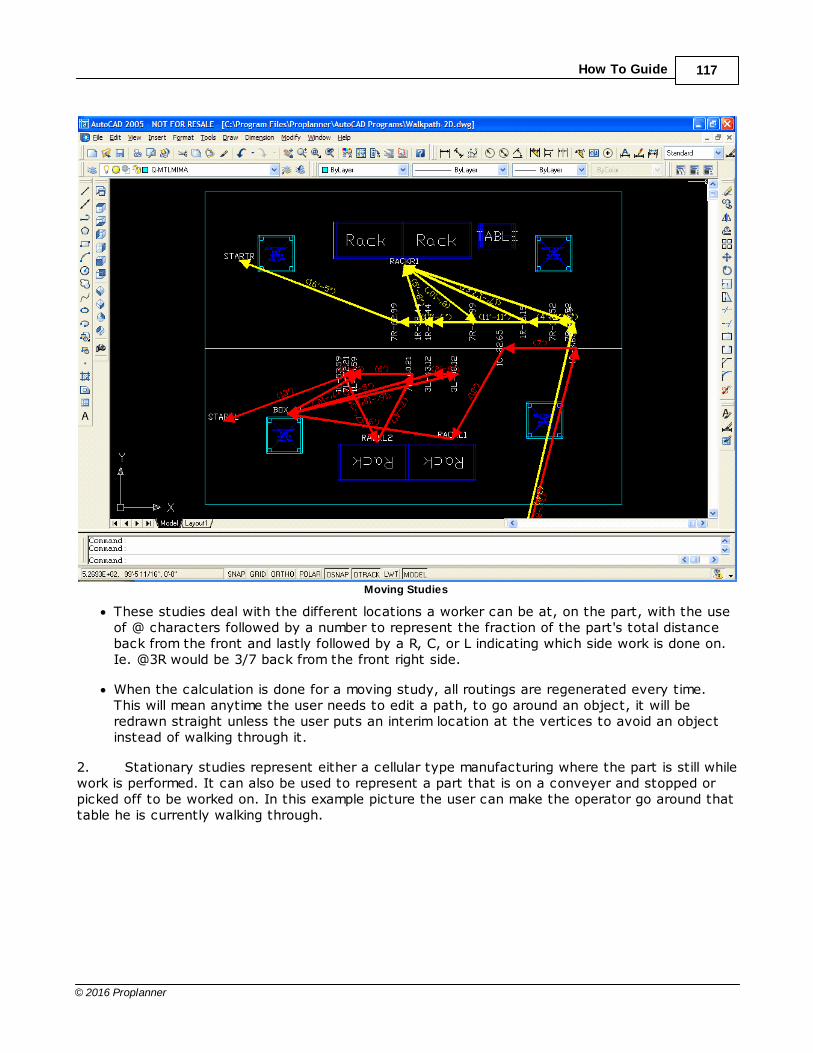
How To Guide 117
© 2016 Proplanner
Moving Studies
· These studies deal with the different locations a worker can be at, on the part, with the useof @ characters followed by a number to represent the fraction of the part's total distanceback from the front and lastly followed by a R, C, or L indicating which side work is done on.Ie. @3R would be 3/7 back from the front right side.
· When the calculation is done for a moving study, all routings are regenerated every time.This will mean anytime the user needs to edit a path, to go around an object, it will beredrawn straight unless the user puts an interim location at the vertices to avoid an objectinstead of walking through it.
2. Stationary studies represent either a cellular type manufacturing where the part is still whilework is performed. It can also be used to represent a part that is on a conveyer and stopped orpicked off to be worked on. In this example picture the user can make the operator go around thattable he is currently walking through.

Troubleshoot118
© 2016 Proplanner
Stationary Studies
Multi-station, operator, and part
1. Multiple operators are created whenever more operators are referenced within the routing.
2. Multiple stations can be simulated by spacing the work locations in different cells or furtherdown the part path if it is a moving study. These are defined on the stations tab by entering thedistance along the part path at which the station starts and how long the station is.
3. Multiple parts are simulated by cycles. These are explained below.
4. For a system of stations linked together along a moving part line, the operators will need tohave a station defined on the stations tab and assigned to them on the operators tab, to ensurethey don't start working until the part enters their station.
Cycles
1. Cycles create a new part going down the line.

How To Guide 119
© 2016 Proplanner
2. There are two ways to define the start of a new cycle. The start time can be absolute,starting from time 0, or relative, starting from the beginning of the previous part's time.
3. Absolute start times are noted by a plain number being input in the cycle time field.
4. For relative start times a @ is used in front of the number.
5. If the first cycle takes too long, the second cycle will start later due to waiting on theoperator. These results will be very obvious when the moving part study is animated.
Synchronization
1. Synchronization can be used to make sure that all included operators have a mutual starttime.
2. The Synchronization line is just a line linking up to four operators that will begin thefollowing tasks after their preceding tasks are complete. The operation checks to see that allroutings before it's row are found true before any of the synchronized operator's routings after thisrow can begin.
3. If the operators need to be working on the same task, an equal time for their process atthis location can be given to both of them.
Predetermined time parsing
1. The pre-loaded parsers can be set to read input in predetermined time systems such asModapts, MTM, and user defined systems.
2. The output will be in either seconds or decimal minutes.
3. The WPP can also create walk type element data to update the walk codes.
User defined time parsing
1. Using this type of parsing is just like using the MTM parser, however; the operator can openthe user-k1.csv and edit key words and their times to personalize their own standard.
2. Exact details on the format of this file can be found in the user manual.
3. Once the desired key words are defined and times are assigned to them, go to theLicensing/Settings (also known in older versions as options/help) tab and set the Process ParseDefault type to User-K1.
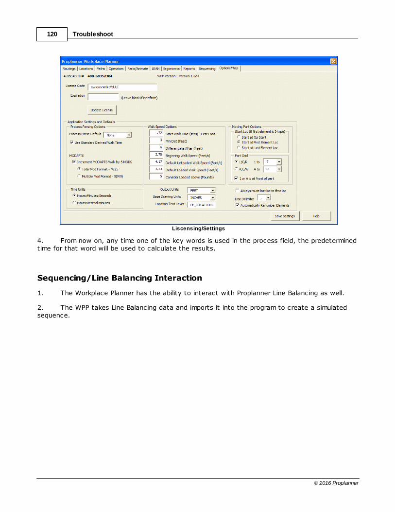
Troubleshoot120
© 2016 Proplanner
Liscensing/Settings
4. From now on, any time one of the key words is used in the process field, the predeterminedtime for that word will be used to calculate the results.
Sequencing/Line Balancing Interaction
1. The Workplace Planner has the ability to interact with Proplanner Line Balancing as well.
2. The WPP takes Line Balancing data and imports it into the program to create a simulatedsequence.
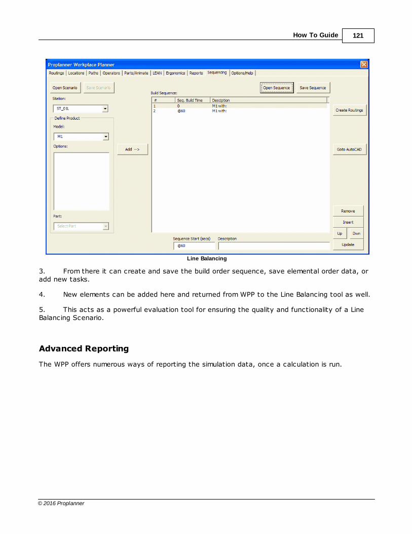
How To Guide 121
© 2016 Proplanner
Line Balancing
3. From there it can create and save the build order sequence, save elemental order data, oradd new tasks.
4. New elements can be added here and returned from WPP to the Line Balancing tool as well.
5. This acts as a powerful evaluation tool for ensuring the quality and functionality of a LineBalancing Scenario.
Advanced Reporting
The WPP offers numerous ways of reporting the simulation data, once a calculation is run.
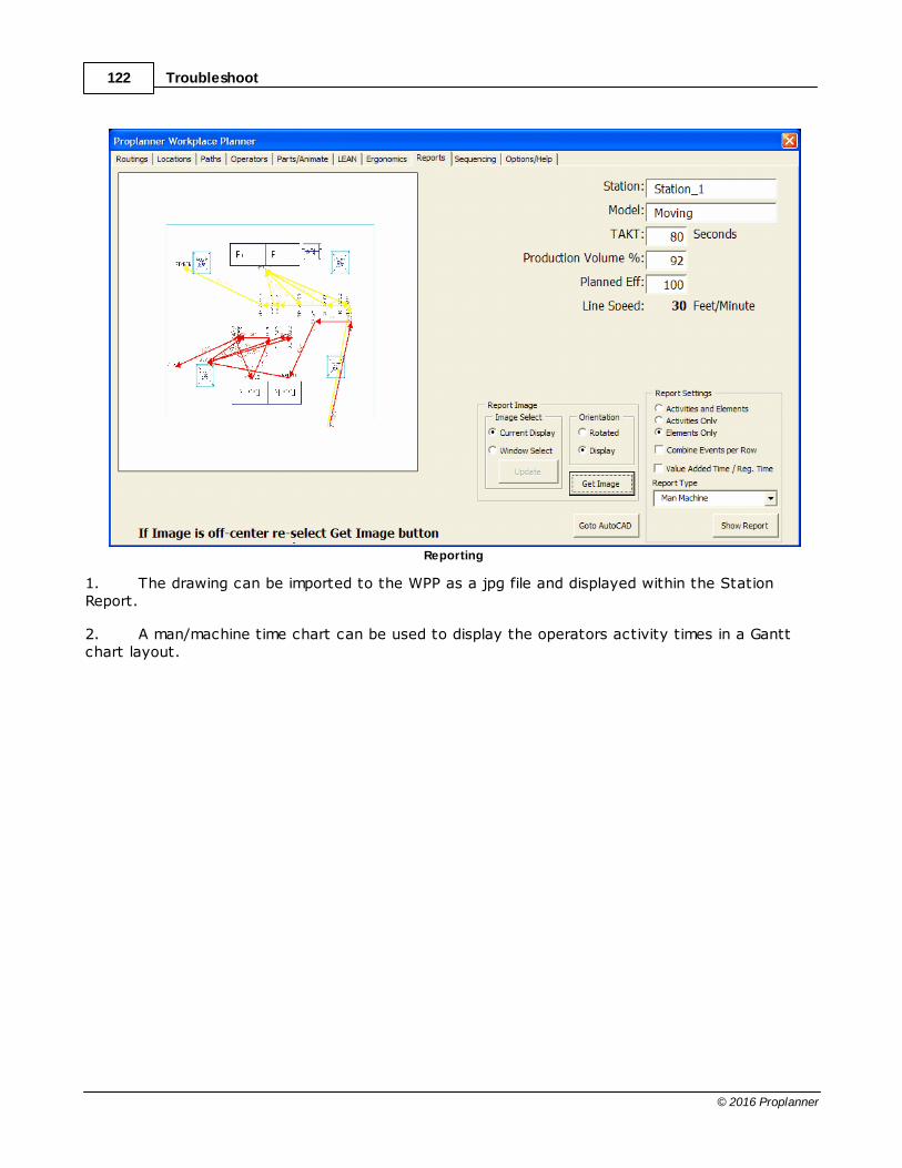
Troubleshoot122
© 2016 Proplanner
Reporting
1. The drawing can be imported to the WPP as a jpg file and displayed within the StationReport.
2. A man/machine time chart can be used to display the operators activity times in a Ganttchart layout.

How To Guide 123
© 2016 Proplanner
Man/Machine Time Chart
3. The station report is the comprehensive report file for all the time, distance, andperformance data, calculated within the Workplace Planner.
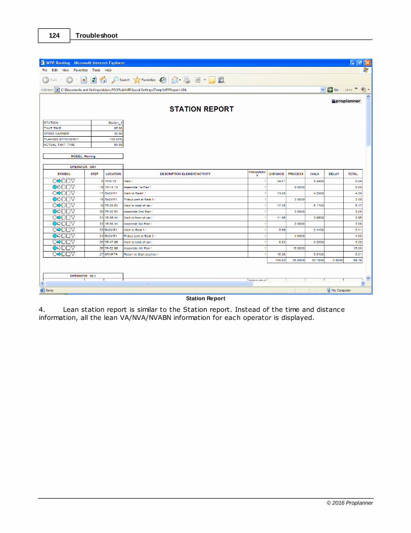
Troubleshoot124
© 2016 Proplanner
Station Report
4. Lean station report is similar to the Station report. Instead of the time and distanceinformation, all the lean VA/NVA/NVABN information for each operator is displayed.

How To Guide 125
© 2016 Proplanner
LEAN Station Report
Animation
1. Once the calculations have been completed, the WPP can be used to animate theoperator's performance.

Troubleshoot126
© 2016 Proplanner
Animation
2. This can take place in the static 2-D view or 3-D if the blocks and drawing was originallycreated in this perspective.
3. The trace file can also be saved to be used with other 3-D animation engines.
4. Operator and one car block is included with the demo files. To replace these in thesimulation with custom blocks, the user needs only place the desired blocks within the drawingbefore opening WPP. They will be available to set as the part or operator blocks from then on.
5. The animation speed can be changed by altering the increments at which AutoCAD renders.The smaller the increment, the slower the animation will move.
6. These animations are a powerful tool in picking up incorrect routing information that maynot have been obvious in the calculation output.
Robot analysis
1. To simulate a robot working, the drawing needs to be loaded as usual. The effective workzone of the robot should also be defined within the drawing to help spot when the work may needto be moved closer.
How To Guide 127
© 2016 Proplanner
2. The main difference is that the robot arm will be simulated by a block representing themanipulator and not the entire arm. It will calculate the times for the operations and travel of themanipulator itself.
3. Note that the WPP will not alert when there are interference problems with the manipulatorarm and the surrounding environment. This tool can be used to identify problems if the operator'spath crosses paths between the active manipulator and its base, seen in the animation.
4. To show interactions between the manipulator and the worker, a synchronize route will beneeded to make them meet at the right place and time. This will show when delays are added dueto one waiting on the other.
5. When these interactions are calculated, the man/machine time chart can be generated onthe reports tab where the man and machine times will be optionally displayed in a chart wheremachine time is displayed parallel to manual labor times.

Troubleshoot128
© 2016 Proplanner
9 Appendix
Application Limitations
Application Layers
Application Blocks
File Formats

129
© 2016 Proplanner
9.1 Application LimitationsThese application limitations have been defined in order to limit potentially excessive memoryrequirements of the application. If these limits prove constraining for certain situations, please contactyour Proplanner representative with your specific request. Input Routing Lines (file length): 2,000 TotalFlow Paths: 1,000 TotalOperators: 25 TotalDynamic Cycles: 25 TotalLocations: 2,000 TotalSynchronous Operators: 4 TotalManual Flow Path Segments: 10 TotalPart Flow Path Segments: 5 Total
9.2 Application LayersAll Proplanner layers begin with “PP_”. The application will consistently add and remove graphics fromthose layers. Proplanner will not alter any graphics on layers other than those beginning with “PP_”. Note: opname is the operator name specified in the routing file PP_LOCATIONS (contains the location text)PP_FLOW-opname (contains the flow paths for the specified operator)PP_FLOW-ARO-opname (contains arrows and text labels for the flow paths)PP_PART-PATH (contains the polyline that defines the part path)PP_PART-LOCATIONS (contains the temporary locations along the part path) Also: Animation of operators occurs on the respective PP_FLOW layer for that operator. Animation of thepart occurs on the PP_PART-PATH layer. Thus blocks being animated will assume the color of therespective operators layer color provided that those blocks were defined on layer 0 with their entitieshaving the color property of BYLAYER.
9.3 Application Blocks
· Proplanner will create a block called PP_ARROW for representing the arrowheads along the flowlines.
· Proplanner will also create a person block PP_PERSON and· A part block PP_PART if the user selects animation and does not specify any different blocks to be
animated.
9.4 File Formats
Input File Format
Output File Formats
Routing file (CSV)
Location file (LOC)
Path file (PTH)
Trace file (TRC)

Appendix130
© 2016 Proplanner
***
9.4.1 Input File FormatThe input file is a comma delimited file with a CSV extension. As such, no commas are allowed within thetext in a field. Proplanner can also read the output files as input files. In this situation, Proplanner willignore the first row that specifies the distance units (since it will also ignore those distances) and alsothe last rows from the word SUMMARY on to the end of the file.
Column Data Value
1 Element ID (Integer Number 1-2000)
2 Element Type (F/P/S/T/M/X)
3 Operator (String up to 10 Chars, or 3 opers sep. by dash
4 Process Code, a slash seperates LCode from RCode
5 From Loc/LCode (based on F/P), (String up to 25 Chars)
6 LCode Desc, (String up to 255 Chars)
7 To Loc/RCode (based on F/P), (String up to 25 Chars)
8 RCode Desc, (String up to 255 Chars)
9 Frequency, (Real Number 0-inf)
10 Distance (only used on F), (Real Number 0-inf)
Specified in Feet or Meters depending on first row value
11 Time, (Real Number 0-inf) in seconds
12 LEAN % (Integer from 0 to 100)
13 Weight (String FHK code prefixes whole number weight)
14 Special Codes (String up to 10 Chars)
15 Miscellaneous user field [OPTIONAL]
16 Activity ID information from Proplanner (Proplanner USE ONLY) [OPTIONAL]
Sample Input File
1M OPR1 G1A 1 0 0.072 0
2M OPR1 R1A 1 0 0.09 0
3F OPR1 FIXTURE Desc TBAR1 1 9.05439 1.81088 0
4M OPR1 G1A 1 0 0.072 0
5M OPR1 R1A 1 0 0.09 0
6F OPR1 TBAR1 Desc RACK1 1 6.9345 1.3869 0
7F OPR1 RACK1 Desc RACK3 1 13.3539 2.67079 0
8F OPR1 RACK3 Desc TABLE 1 7.55798 1.5116 0
9M OPR1 G1A 1 0 0.072 0
10M OPR1 R1A 1 0 0.09 0
11F OPR1 TABLE Desc RACK4 1 7.86218 1.57244 0
12F OPR1 RACK4 Desc FIXTURE2 1 8.66101 1.7322 0
13M OPR1 M10B/R10B 1 0 0.072 0
14F OPR1 FIXTURE2 Desc TBAR2 1 4.28715 0.85743 0
15F OPR1 TBAR2 Desc FIXTURE 1 16.0786 3.21571 0
16F OPR1 FIXTURE Desc RACK2 1 19.913 3.98261 017F OPR1 RACK2 Desc FIXTURE 1 19.8488 3.96977 0

File Formats 131
© 2016 Proplanner

Appendix132
© 2016 Proplanner
9.4.2 Output File FormatsRouting file (CSV)Location file (LOC)Path file (PTH)Trace file (TRC)

File Formats 133
© 2016 Proplanner
9.4.2.1 Routing File (CSV)
The WPP application automatically adds a first line to the original routing CSV file that specifies the unitsof measurement for the distances in that file. The WPP also adds a Summary table at the end thatcontains the operator total walk distance and time for each unique operator referenced in the routingfile. File Example FEET
CSV File Example

Appendix134
© 2016 Proplanner
9.4.2.2 Location File (LOC)
The WPP application can create a comma-delimited text file that contains the X,Y coordinates of alllocations in the drawing, as well as the limits of the drawing for use in scaling these values into othercoordinate systems. File Example
LOCATIONS (NAME X Y)
START -41.27886074 959.0241136
STARTL-1 -14.39969858 959.4311767
RACKL-1 184.3432071 895.1150395
BOX1 336.2512049 944.3698027
STARTR-1 -37.20626017 1054.277127
RACKR-1 180.2706065 1101.089505
L-6.34 365.5085379 1002.456442
L-20.34 225.5085379 1002.45643
LW<B-29.23 197.0274325 966.4564334
LW<B-34.23 147.0274325 966.456429
LW-43.00 -0.453680626 966.4564263
LW-46.00 -30.45368063 966.4564236
LW<D-52.81 81.95607918 966.4564466
LW<D-64.81 -38.04392082 966.4564362
RW-6.66 362.0426321 1038.456442
RW-15.66 272.0426321 1038.456434
RW<D-22.97 379.1037947 1038.456458
RW<D-25.97 349.1037947 1038.456456
RW-29.51 134.1038002 1038.456456
RW-31.51 114.1038002 1038.456454
RW<D-38.30 226.4649621 1038.456476
RW<D-53.30 76.46496209 1038.456463
DRAWING EXTENTS (MINX MINY MAXX MAXY) in NCHES
-122.8498 478.9541 428.6794 1182.4564

File Formats 135
© 2016 Proplanner
9.4.2.3 Path File (PTH)
The WPP application can create a comma-delimited text file that contains the X,Y coordinates of all pathvertices in the drawing, as well as the limits of the drawing for use in scaling these. Additionalinformation about the path is also provided (such as distance, frequency, operator, from and to location) File Example
Path File Example

Appendix136
© 2016 Proplanner
Example

File Formats 137
© 2016 Proplanner
9.4.2.4 Trace File (TRC)
The WPP application can create a text file that contains the animation event sequence for all operatorsin a WPP Analysis. This trace file includes the event time (in seconds from time 0) as well as the eventAT/FROM location and event TO location if appropriate. Position and Path information reference bylocations and paths in this trace file can be found in the Locations (LOC) and Paths (PTH) output files. LEGEND of Event TypesD – User defined Delay at beginning of operator cycle (such as waiting for part to enter workstation)W - Walking FROM a location TO a locationP – Processing AT a static locationR – Processing AT a moving locationI – Internal delay at a static position caused by operator synchronizationL – Internal delay at a moving position caused by operator synchronization File ExampleOPERL-1W6:STARTL-1/L-5.96R20:L-5.96/L-19.96W22:L-19.96/RACKL-1W24.8:RACKL-1/BOX1P26.8:BOX1W29.1:BOX1/LW<B-29.10R34.1:LW<B-29.10/LW<B-34.10W37.3:LW<B-34.10/BOX1W42.9:BOX1/LW-42.93R45.9:LW-42.93/LW-45.93W49.6:LW-45.93/RACKL-1P50.6:RACKL-1W53:RACKL-1/LW<D-52.98R65:LW<D-52.98/LW<D-64.98W66.1:LW<D-64.98/STARTL-1 OPERR-1W5.8:STARTR-1/RW-5.84R14.8:RW-5.84/RW-14.84W16.8:RW-14.84/RACKR-1P18.8:RACKR-1W22.4:RACKR-1/RW<D-22.37R25.4:RW<D-22.37/RW<D-25.37W28.9:RW<D-25.37/RW-28.91R30.9:RW-28.91/RW-30.91W32.3:RW-30.91/RACKR-1I45.9:RACKR-1P49.9:RACKR-1W52.1:RACKR-1/RW<D-52.11R67.1:RW<D-52.11/RW<D-67.11W68.8:RW<D-67.11/STARTR-1