Embed Size (px)
Citation preview
ISRO-PAX-300 Issue 5, November 2012
Workmanship Standards for the Fabrication of Electronic Packages
ISRO Reliability Standards
Directorate of Systems Reliability and Quality, ISRO Headquarters, Bangalore


Indian Space Research OrganisationDepartment of SpaceGovernment of IndiaAntariksh Bhavan New BEL Road, Bangalore - 560 231, IndiaTelephone : +91-80-2341 5241/2217 2333Fax : +91-80-23415328e-mail : [email protected]
¦ÉÉ®úiÉÒªÉ +xiÉÊ®úIÉ +xÉÖºÉÆvÉÉxÉ ºÉÆMÉ`öxÉ+xiÉÊ®úIÉ Ê´É¦ÉÉMÉ
¦ÉÉ®úiÉ ºÉ®EòÉ®
+xiÉÊ®úIÉ ¦É´ÉxÉ
xªÉÚ ¤ÉÒ.<Ç.B±É. ®úÉäb÷, ¤ÉåMɱÉÚ®ú-560 231, ¦ÉÉ®úiÉ
nÚ®¦ÉɹÉ: +91-80-2341 5241/2217 2333
¡èòCºÉ: +91-80-23415328
Dr. K. RadhakrishnanChairman
MESSAGE
ISRO Reliability Standards, addressing the various disciplines of Engineering, have been in vogue for
almost three decades now. These standards are followed across ISRO centres as well as external work
centers for design, fabrication, testing, analysis and other processes involved in the realization of Launch
Vehicles, Spacecraft, Space Applications, Ground support systems and other launch infrastructure. The
need for standardization of processes towards achieving high reliability systems can never be over
emphasized, and ISRO Reliability Standards are just an attempt towards explicitly stating this.
With the advent of newer techniques and with the evolution of technology itself, over the last 30 years,
it has become essential to revisit the existing ISRO Reliability Standards and revise and update the
standards wherever essential. Towards this, the Directorate of Systems Reliability and Quality (DSRQ) at ISRO Headquarters
has taken an initiative to re-invigorate the reach and visibility of ISRO Reliability standards across all the Centres of ISRO. Specific
Inter-centre teams were formed to revise each of these documents and I would like to place on record their commendable
efforts in bringing out these documents.
There is a pressing need for ensuring uniformity of practices, across various functions of design, fabrication, testing, review
mechanisms etc., across the centres and units of ISRO. Towards this goal, the mandatory adoption of ISRO Reliability Standards
will ensure standardization in quality processes and products. I am certain that this will go a long way towards ensuring overall
system level Quality and Reliability and in achieving the goal of zero defects in the delivery of space systems of ISRO.
K Radhakrishnan
Chairman, ISRO

PREFACE
ISRO Reliability standards are a result of the need for standardization of processes towards achieving high reliability systems.
The transfer of knowledge and techniques from the seniors to their successors is best done with proper documentation and
checklists translating the entire know-how into black and white.
This document on ‘Workmanship standards for the fabrication of electronic packages’ addresses the complete
assembly of launch vehicle, spacecraft, and critical check-out systems for all projects of ISRO, from the point of view of quality
and workmanship requirements to be met during fabrication of electronic and electromechanical packages. This document has
undergone a large scale revision, compared to its previous issue, considering the advancement of technology. The details regarding
facility, tools, materials, soldering and cleaning of Printed Circuit Board assemblies are discussed at length. Particulars related
to crimping, interconnecting cables, harnesses and wiring are also given specific attention. The role of Quality professionals and
aspects of Quality assurance are also elucidated. Additional details regarding polymeric applications, conformal coating, electro
static discharge, repair and rework and bonded stores are also made clear.
It is deemed essential that these standards be strictly adhered to, in order to ensure uniformity of practices across ISRO centers
and achieve zero defects in the delivery of space systems.
I am grateful to Chairman ISRO, for being the source of inspiration in the release of these documents. Thanks are also due to the
centre Directors for their encouragement. I am also thankful to the Heads of SR Entities/Groups of various ISRO centres for
their relentless support and guidance. I am also indebted to the members of the Integrated Product Assurance Board (IPAB) for
the meticulous review of these documents. I also owe gratitude to the task team members and other experts for putting efforts
in the realization of these documents. I am glad to carry forward this rich lineage of ISRO reliability standards, championed by
Shri R Aravamudan, a revered pioneer in the area of Quality & Reliability in ISRO.
S Selvaraju
Sr. Advisor (SRQ)
Directorate of Systems Reliability & QualityISRO HeadquartersAntariksh BhavanNew BEL Road, Bangalore -560231Ph :080 - 2341 5414 Fax :080 – 2341 2826Cell:09448397704Email: [email protected]
S Selvaraju Senior Advisor, Systems Reliability and Quality

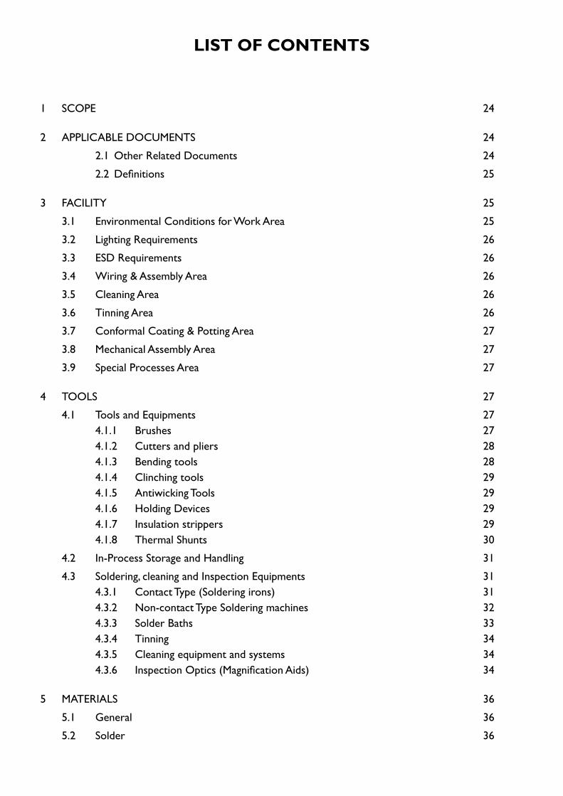
LIST OF CONTENTS
1 SCOPE 24
2 APPLICABLE DOCUMENTS 24
2.1 Other Related Documents 24
2.2 Definitions 25
3 FACILITY 25
3.1 Environmental Conditions for Work Area 25
3.2 Lighting Requirements 26
3.3 ESD Requirements 26
3.4 Wiring & Assembly Area 26
3.5 Cleaning Area 26
3.6 Tinning Area 26
3.7 Conformal Coating & Potting Area 27
3.8 Mechanical Assembly Area 27
3.9 Special Processes Area 27
4 TOOLS 27
4.1 Tools and Equipments 274.1.1 Brushes 274.1.2 Cutters and pliers 284.1.3 Bending tools 284.1.4 Clinching tools 294.1.5 Antiwicking Tools 294.1.6 Holding Devices 294.1.7 Insulation strippers 294.1.8 Thermal Shunts 30
4.2 In-Process Storage and Handling 31
4.3 Soldering, cleaning and Inspection Equipments 314.3.1 Contact Type (Soldering irons) 314.3.2 Non-contact Type Soldering machines 324.3.3 Solder Baths 334.3.4 Tinning 344.3.5 Cleaning equipment and systems 344.3.6 Inspection Optics (Magnification Aids) 34
5 MATERIALS 36
5.1 General 36
5.2 Solder 36
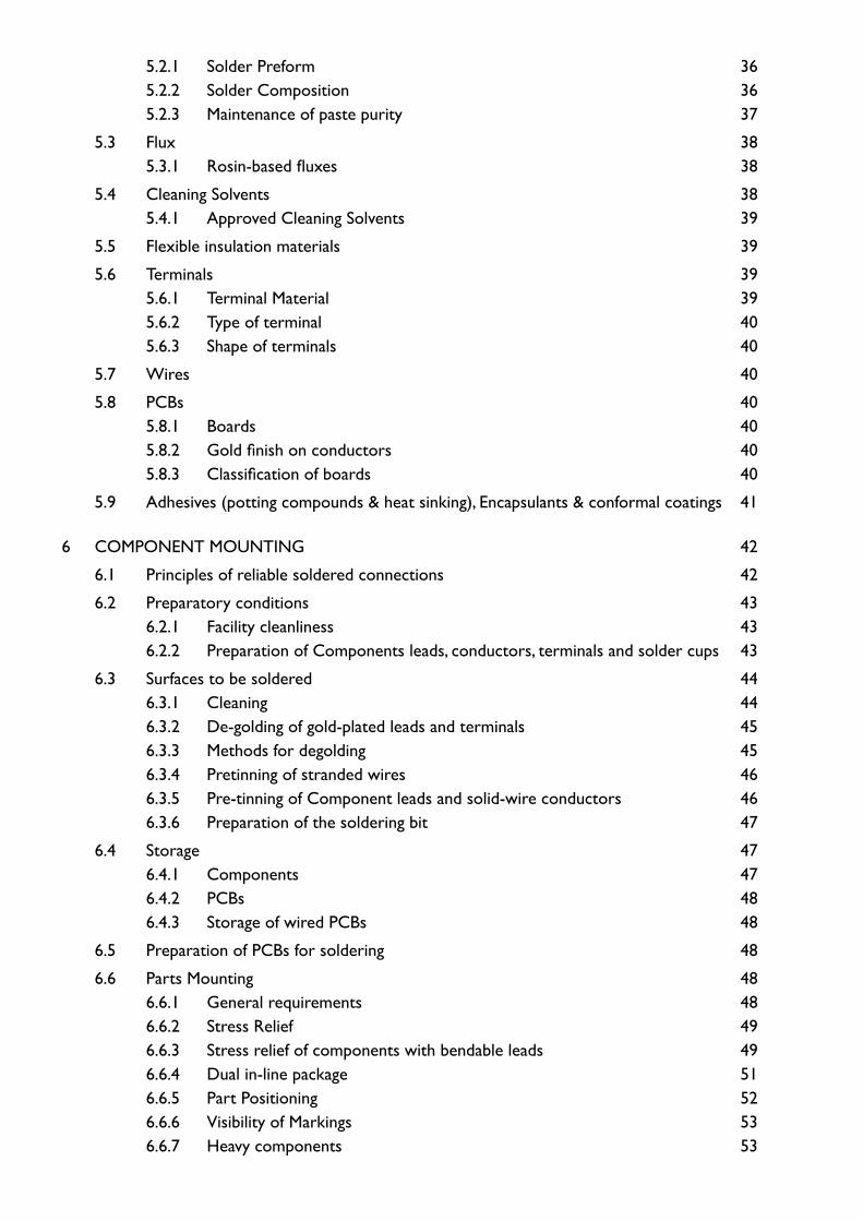
5.2.1 Solder Preform 365.2.2 Solder Composition 365.2.3 Maintenance of paste purity 37
5.3 Flux 385.3.1 Rosin-based fluxes 38
5.4 Cleaning Solvents 385.4.1 Approved Cleaning Solvents 39
5.5 Flexible insulation materials 39
5.6 Terminals 395.6.1 Terminal Material 395.6.2 Type of terminal 405.6.3 Shape of terminals 40
5.7 Wires 40
5.8 PCBs 405.8.1 Boards 405.8.2 Gold finish on conductors 405.8.3 Classification of boards 40
5.9 Adhesives (potting compounds & heat sinking), Encapsulants & conformal coatings 41
6 COMPONENT MOUNTING 42
6.1 Principles of reliable soldered connections 42
6.2 Preparatory conditions 436.2.1 Facility cleanliness 436.2.2 Preparation of Components leads, conductors, terminals and solder cups 43
6.3 Surfaces to be soldered 446.3.1 Cleaning 446.3.2 De-golding of gold-plated leads and terminals 456.3.3 Methods for degolding 456.3.4 Pretinning of stranded wires 466.3.5 Pre-tinning of Component leads and solid-wire conductors 466.3.6 Preparation of the soldering bit 47
6.4 Storage 476.4.1 Components 476.4.2 PCBs 486.4.3 Storage of wired PCBs 48
6.5 Preparation of PCBs for soldering 48
6.6 Parts Mounting 486.6.1 General requirements 486.6.2 Stress Relief 496.6.3 Stress relief of components with bendable leads 496.6.4 Dual in-line package 516.6.5 Part Positioning 526.6.6 Visibility of Markings 536.6.7 Heavy components 53
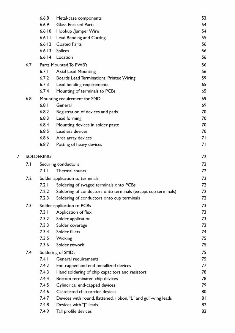
6.6.8 Metal-case components 536.6.9 Glass Encased Parts 546.6.10 Hookup /Jumper Wire 546.6.11 Lead Bending and Cutting 556.6.12 Coated Parts 566.6.13 Splices 566.6.14 Location 56
6.7 Parts Mounted To PWB’s 566.7.1 Axial Lead Mounting 566.7.2 Boards Lead Terminations, Printed Wiring 596.7.3 Lead bending requirements 656.7.4 Mounting of terminals to PCBs 65
6.8 Mounting requirement for SMD 696.8.1 General 696.8.2 Registration of devices and pads 706.8.3 Lead forming 706.8.4 Mounting devices in solder paste 706.8.5 Leadless devices 706.8.6 Area array devices 716.8.7 Potting of heavy devices 71
7 SOLDERING 72
7.1 Securing conductors 727.1.1 Thermal shunts 72
7.2 Solder application to terminals 727.2.1 Soldering of swaged terminals onto PCBs 727.2.2 Soldering of conductors onto terminals (except cup terminals) 727.2.3 Soldering of conductors onto cup terminals 72
7.3 Solder application to PCBs 737.3.1 Application of flux 737.3.2 Solder application 737.3.3 Solder coverage 737.3.4 Solder fillets 747.3.5 Wicking 757.3.6 Solder rework 75
7.4 Soldering of SMDs 757.4.1 General requirements 757.4.2 End-capped and end-metallized devices 777.4.3 Hand soldering of chip capacitors and resistors 787.4.4 Bottom terminated chip devices 787.4.5 Cylindrical end-capped devices 797.4.6 Castellated chip carrier devices 807.4.7 Devices with round, flattened, ribbon, “L” and gull-wing leads 817.4.8 Devices with “J” leads 827.4.9 Tall profile devices 82
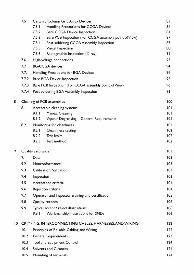
7.5 Ceramic Column Grid Array Devices 837.5.1 Handling Precautions for CCGA Devices 847.5.2 Bare CCGA Device Inspection 847.5.3 Bare PCB Inspection (For CCGA assembly point of View) 877.5.4 Post soldering CCGA Assembly Inspection 877.5.5 Visual Inspection 887.5.6 Radiographic Inspection (X-ray) 91
7.6 High-voltage connections 93
7.7 BGA/CGA devices 94
7.7.1 Handling Precautions for BGA Devices 94
7.7.2 Bare BGA Device Inspection 95
7.7.3 Bare PCB Inspection (For CCGA assembly point of View) 96
7.7.4 Post soldering BGA Assembly Inspection 96
8 Cleaning of PCB assemblies 100
8.1 Acceptable cleaning systems 1018.1.1 Manual Cleaning 1018.1.2 Vapour Degreasing – General Requirements 101
8.2 Monitoring for cleanliness 1028.2.1 Cleanliness testing 1028.2.2 Test limits 1028.2.3 Test method 102
9 Quality assurance 103
9.1 Data 103
9.2 Nonconformance 103
9.3 Calibration/ Validation 103
9.4 Inspection 103
9.5 Acceptance criteria 104
9.6 Rejection criteria 104
9.7 Operator and inspector training and certification 105
9.8 Quality records 106
9.9 Typical accept / reject illustrations 1069.9.1 Workmanship illustrations for SMDs 106
10 CRIMPING, INTERCONNECTING CABLES, HARNESSES, AND WIRING 122
10.1 Principles of Reliable Cabling and Wiring 122
10.2 General requirements 123
10.3 Tool and Equipment Control 124
10.4 Solvents and Cleaners 124
10.5 Mounting of Terminals 124
10.6 Attachment of conductors to terminals, solder cups and cables 12610.6.1 General 12610.6.2 Conductors 12610.6.3 Breakouts from cables 12610.6.4 Insulation clearance 12710.6.5 Solid hook-up wire 12710.6.6 Stress relief 12710.6.7 Insulation clearance 127
10.7 Stripping insulation from conductors and cable 12910.7.1 Stripping Round Conductors 12910.7.2 Stripping Jackets over Shields 130
10.8 Turret and Straight Pin Terminals 13010.8.2 Bifurcated terminals 13210.8.3 Bottom route 13210.8.4 Top route 13310.8.5 Combination of top and bottom routes 13410.8.6 Pierced terminals 13510.8.7 Solder cups (connector type) 13610.8.8 Insulation sleeving 136
10.9 Wire and cable interconnections 13710.9.1 General 13710.9.2 Preparation of shielded wires and cables 13710.9.3 Pre-assembly 13710.9.4 Soldering procedures 13810.9.5 Cleaning 13910.9.6 Workmanship 13910.9.7 Connection of stranded wires to PCBs 139
10.10 Interconnecting cable/harness fixturing 14110.10.1 General 14110.10.2 Mockup and Wiring Board Design Parameter 14110.10.3 Temporary Identification 14110.10.4 Interconnecting Cable and Harness Protection 141
10.11 Forming wires and cables into harnesses 14210.11.1 General 14210.11.2 Fabric Braid Sleeving (Pre-woven) 14710.11.3 Lacing 14810.11.4 Continuous Lacing 15010.11.5 Straps 15210.11.6 Insulation Sleeving/Tubing 153
10.12 Cable shielding and shield termination 15410.12.1 General RFI/EMI Practices 15410.12.2 Shield Termination 15410.12.3 Individual Shield Termination Using Heat Shrinkable Solder Sleeves 15510.12.4 Long Lengths of Shrinkable Sleeving 15610.12.5 Floating Shield Terminations 157
10.12.6 Unshielded Wire Exposure and Total Length of Grounding Wires 157
10.13 Wire crimping 15810.13.1 Crimping Requirements: 15910.13.2 Crimping Operations 16110.13.3 Crimping Tools 16110.13.4 Calibration of Crimping Tools 16710.13.5 Insulation Clearance 16810.13.6 Insulation Support 16810.13.7 Integrity of Crimped Connections 16810.13.8 Examination of Test Samples 17010.13.9 Inspection 17010.13.10 Inspection Prior to Crimping 17010.13.11 Microsectioning of Crimped Pin: 171
10.14 Connector assembly 17210.14.1 Assembly of Crimp-Type Connectors (Including Terminal Junctions) 172
10.15 Interconnecting harness and cable cleaning 17610.15.1 General 17610.15.2 Cleaning the Harness Assembly 17610.15.3 Cleaning Harness Connectors 17610.15.4 Cleaning Coaxial Connectors (Assembled) 17610.15.5 Harness handling and protection 17710.15.6 Interconnecting Harness and Cable Storage Protection 17710.15.7 Connector mating 179
10.16 Testing and inspection 18010.16.1 General 18010.16.2 Wet Probe Testing 180
10.17 Quality assurance provisions 18110.17.1 Method of Inspection. 18110.17.2 Magnification Aids 18210.17.3 Documentation Verification 182
10.18 Wire visual aids and illustrations 18810.18.1 Wiring: connectors, cabling, and harnessing - wire dress to connectors 18810.18.2 Wiring: connectors, cabling, and harnessing - stress relief shrinkable sleeving on solder cups 18910.18.3 Wiring: connectors, cabling, and harnessing, wire preparation, thermal stripping 19010.18.4 Wire preparation: mechanical stripping 19110.18.5 Wiring: connectors, cabling, and harnessing, wire preparation, thermal stripping 19310.18.6 Wiring: connectors, cabling, and harnessing, wire preparation, tinning stranded conductors 19510.18.7 Wiring: connectors, cabling, and harnessing - installation of straps 19510.18.8 Crimps: insulation clearance 19710.18.9 Crimps: Acceptable and Unacceptable 197
10.19 Critical problems in coaxial cable assembly 199
11 SEMI-RIGID CABLE ASSEMBLY 202
11.1 Introduction 202
11.2 Principles of Reliable Soldered or Crimped Semi-Rigid Cable Connections 203
11.3 Material & Tools 203
11.4 Materials 20311.4.1 Processes 204
11.5 Semi Rigid Cable Assembly Process 20811.5.1 General 20811.5.2 Cable Straightening 208
11.6 Cable Assembly Drawing 209
11.7 Cable Cutting 209
11.8 Preconditioning Heat Treatment 211
11.9 Cable Templates 211
11.10 Cable Bending 211
11.11 Cable Bending General Requirements 21211.11.1 Cable Bending Tools & Aids 21311.11.2 Cable Bending Procedure 214
11.12 Cable Assembly Support Requirements 216
11.13 Cable Outer Jacket Stripping 21611.13.1 Inspection of Stripped Cable Ends 217
11.14 Stripping the Dielectric 21811.14.1 Stripping the Dielectric Alone After Outer Jacket Stripping 21811.14.2 Stripping of Dielectric & Outer Jacket Simultaneously 219
11.15 Centre Conductor End Forming 219
11.16 Preparation for soldering of Cable Outer Jacket and Centre Conductor Tinning 220
11.17 Degolding of Gold Plated Connector Parts and Pre-tinning 22011.17.1 De-golding By Three Solder Pot Method 22011.17.2 Solder Preforms 22211.17.3 Assembly Plan 22511.17.4 General Requirements for Connector Assembly 225
11.18 Specific Requirements 22611.18.1 SMA Right Angle Connector 22611.18.2 SMA female connector 226
11.19 Solder Assembly of Semi Rigid Cables 22711.19.1 Straight cable end connector 227
11.20 Right Angle Cable End Connector: 230
11.21 Teflon Bush Insertion In Connector 23311.21.1 In Case of Straight SMA Connector 23311.21.2 In case of TNC connector 233
11.22 Semi Rigid Cable Preconditioning 23311.22.1 Necessity 23311.22.2 Phase-I Preconditioning 234
11.22.3 Phase-II Preconditioning 23411.22.4 Phase-III Preconditioning 235
11.23 Inspection & Acceptance/Rejection Criteria 23611.23.1 Inspection of Cable After Cutting To Required Length 23611.23.2 Inspection after Cable Bending 23711.23.3 Inspection After Cable Jacket Cutting, Dielectric Stripping Pin Forming And Tinning 23811.23.4 Inspection of De-Golded Connector Parts 24011.23.5 Inspection of Pin Soldering 24011.23.6 Inspection After Soldering of Connector Parts To Sem-irigid Cable Before Phase III Preconditioning 24111.23.7 Inspection of Finished Cable Assembly after Phase –III reconditioning 242
11.24 Specific 24411.24.1 Right angle connector cable assembly 24411.24.2 Straight connector cable assembly 24411.24.3 TNC connector cable assembly 244
11.25 Semi-rigid cable fabrication flow charts 245
11.26 Sample diagram of cable assembly 256
11.27 Typical stress relieving bends used in Semi rigid cable assembly 257
12 POLYMERIC APPLICATIONS 259
12.1 Preparation for polymeric applications 25912.1.1 Surface Preparation 25912.1.2 Masking 25912.1.3 Priming 26012.1.4 Local Potting 26012.1.5 Requirements 260
13 CONFORMAL COATING 270
13.1 Purpose 270
13.2 Safety Precautions 271
13.3 Poly Urethane Type Coating Applications 27113.3.1 Spraying 27113.3.2 Brush Method 27113.3.3 Dipping Method 27113.3.4 Pouring Method 272
13.4 Curing 272
13.5 Parylene Conformal Coating 27213.5.1 Preparation for Coating (For Polyurethane and Parylene) 272
13.6 Application Procedure 27313.6.1 Procedure for coating with Parylene: 273
13.7 Deposition Process 27313.7.1 Sublimation 27313.7.2 Precautions for Local Potting & Conformal Coating 280
13.8 Bonding 28013.8.1 General 28013.8.2 Bonding 280
14 REPAIR & REWORK 281
14.1 Repair/Rework 281
14.2 Repair criteria 281
14.3 Number of repairs 281
14.4 Modifications 28114.4.1 Modification criteria 281
14.5 Number of modifications 281
14.6 Rework 28214.6.1 Rework criteria 28214.6.2 Number of reworks 28214.6.3 Other requirements 282
14.7 Removal of conformal coating 28214.7.1 Requirements 28214.7.2 Procedure 28214.7.3 Acceptance criteria 282
14.8 Solder joint removal and unclinching 28314.8.1 Procedure 28314.8.2 Acceptance criteria 283
14.9 Repair of damaged conductor tracks 28314.9.1 Requirements 28314.9.2 Procedure 28314.9.3 Acceptance criteria 284
14.10 Repair of lifted conductors 28414.10.1 Requirements 28414.10.2 Procedure 28414.10.3 Acceptance criteria 284
14.11 Wire to wire joints 28514.11.1 Requirements 28514.11.2 Procedure 28514.11.3 Acceptance criteria 285
14.12 Removal and replacement of axial and multi lead components 28514.12.1 Requirements 28514.12.2 Procedure 28514.12.3 Acceptance criteria 286
14.13 Removal and replacement of flat pack components 28614.13.1 Procedure 28614.13.2 Acceptance criteria 287
14.14 Modification of component connections 28714.14.1 Requirements 28714.14.2 Procedure 287
14.14.3 Acceptance criteria 288
14.15 Quality assurance 289
14.16 Removal of conformal coating 28914.16.1 Introduction 28914.16.2 Tools and materials 289
14.17 Methods for the removal of conformal coating 28914.17.1 Method for the removal of polyurethane and silicone type coating 289
14.18 Solder joint removal and unclinching 29114.18.1 Introduction 29114.18.2 Tools and materials 29114.18.3 Methods for solder joint removal and unclinching 292
14.19 Repair of damaged conductor tracks 29514.19.1 Introduction 29514.19.2 Tools and materials 29514.19.3 Method for the repair of damaged conductor tracks 295
14.20 Repair of lifted conductors 296
14.21 Methods for repair of lifted conductors 29614.21.1 Method for the use of epoxy under conductor 29614.21.2 Method for the use of epoxy over conductor 297
14.22 Wire to wire joints 29714.22.1 Introduction 29714.22.2 Tools and materials 29714.22.3 Method for wire to wire joining 297
14.23 Addition of Components 29814.23.1 Method for additional component mounting on reverse (non component side) of board 29814.23.2 Method for additional components mounting on component side of board 299
14.24 Method for the addition of a wire link onto metallized cap of chips directly glued on PCB 300
14.25 Method for the addition of a wire link onto terminal pad of soldered chips 300
15 SPECIAL PROCESSES 302
15.1 SPLICING 30215.1.1 General 30215.1.2 General Information 30215.1.3 Design Considerations 30215.1.4 Splicing Methods 30315.1.5 Soldered Splices 303
15.2 Lap Splice 30315.2.1 Preparation. 30415.2.2 Soldering. 30415.3 Lash Splice 30415.3.1 Preparation 304
15.3.2 Soldering 306
15.4 Solder Sleeve 30615.4.1 Preparation 30615.4.2 Soldering. 306
15.5 Crimped Splices 307
15.6 Modified Crimp Contact 307
15.7 Butt Splice 30815.7.1 Preparation. 30915.7.2 Contact Sizing 30915.7.3 Assembly 31015.7.4 Inspection 311
16 ELECTRO STATIC DISCHARGE 312
16.1 Purpose 312
16.2 Applicability 312
16.3 Fundamentals of Electro Static Discharge 312
16.4 Introduction 312
16.5 ESD Modeling 312
16.6 Triboelectrification 31316.6.1 Induction charging 315
16.7 Need of ESD Control 315
16.8 Classifications of ESD Devices 315
16.9 Type of ESD Failure 31616.9.1 Catastrophic failure 31616.9.2 Parametric failure 31616.9.3 Latent failure 316
16.10 ESD Control Program 31716.10.1 ESD Sensitivity Levels 31716.10.2 Methods of ESD Control 31816.10.3 Personnel safety 32016.10.4 ESD protected areas (EPA) 321
16.11 ESD Control Requirements For Facilities 32116.11.1 General 32116.11.2 Identification and access - ESD areas 32116.11.3 Prohibited Materials And Activities 32316.11.4 ESD Protective Work Surfaces 32316.11.5 ESD-Protective floor surfaces 32516.11.6 Personal grounding devices 32616.11.7 Integrity testing of personal grounding devices 32716.11.8 Equipment and facilities 32816.11.9 ESD safe protective packaging 33316.11.10 Clothing requirements 333
16.12 ESDS Item Handling 335
16.12.1 General 33516.12.2 Special Requirements for Highly Sensitive Items 33516.12.3 Equipment 33616.12.4 Identification and marking 337
17 BONDED STORES 341
17.1 Introduction 341
17.2 Environment of the bonded stores 341
17.3 Operation of the bonded stores 34117.3.1 Contents of the bonded stores 341
17.4 Storage 34217.4.1 General 34217.4.2 Electronic Component Storage Area 34217.4.3 Storage of Materials and Chemicals 34317.4.4 Operation 34317.4.5 Operator 34417.4.6 Documentation 344
18 TERMS AND DEFINITIONS 346
19 TECHNICAL STANDARD IMPROVEMENT PROPOSAL 364
19.1 Instructions 364

LIST OF FIGURES
Figure 4.1 : Profiles of correct and incorrect cutters for trimming leads 28
Figure 4.2 : Typical lead forming/bending tool 29
Figure 4.3 : Typical mechanical wire stripper 30
Figure 6.1 : Methods for incorporating stress relief with components having bendable leads 51
Figure 6.2 : Assembly of under filled TO-39 and TO-59, and adhesively staked CKR06 51
Figure 6.3 : Not acceptable body and seal conditions 52
Figure 6.4 : Minimum lead bend 56
Figure 6.5 : Horizontal Mount 57
Figure 6.6 : Radial Leaded Parts 57
Figure 6.7 : Obstruction of solder flow (Not acceptable) 58
Figure 6.8 : Stress Relief Part Termination 58
Figure 6.9 : Bend Angle 59
Figure 6.10 : Lapped Lead Height above Board 60
Figure 6.11 : Lapped Round Termination 61
Figure 6.12 : Lapped Ribbon Leads 62
Figure 6.13 : Clinched Termination 63
Figure 6.14 : Lead Bend 63
Figure 6.15 : Straight-Through Termination 64
Figure 6.16 : Straight-Through Lead Retention 64
Figure 6.17 : Leads with solder termination on both sides 65
Figure 6.18 : Types of terminal swaging 66
Figure 6.19 : Terminal swaging sequence 67
Figure 6.20 : Method of stress relieving parts attached to terminals 68
Figure 6.21 : Fuse mounted on bifurcated, where post is cut 69
Figure 6.22 : Exposed element 71
Figure 7.1 : Solder fillet for plated through holes 74
Figure 7.2 : Solder fillet for non through holes where leads are clinched 75
Figure 7.3 : Mounting of rectangular and square end-capped and end-metallized devices 78
Figure 7.4 : Mounting of bottom terminated chip devices 79
Figure 7.5 : Mounting of cylindrical end-capped devices 80
Figure 7.6 : Mounting of castellated chip carrier devices 81
Figure 7.7 : Mounting of devices with round, flattened, ribbon, “L” and gull-wing leads 81
Figure 7.8 : Mounting of devices with “J” leads 82
Figure 7.9 : Dimensions of tall profile components. 83
Figure 7.10 : Typical CCGA device build -up 84
Figure 7.11 : Typical assembled CCGA device 84
Figure 7.12 : Underside view showing missing column 85
Figure 7.13 : Solder fillet 360° coverage around the column circumference: Accept 86
Figure 7.14 : Side view showing column; column by more than 5°: Reject 86
Figure 7.15 : X-ray view showing voids in column solder joint more than 25%: Reject 87
Figure 7.16 : Example of acceptable solder fillet coverage around column, more than 50%: Accept 88
Figure 7.17 : Example of acceptable column tilt up to 10º 89
Figure 7.18 : CGA mounted on PCB showing columns tilted < 5°: Accept 89
Figure 7.19 : Micrograph of CGA mounted on PCB 90
Figure 7.20 : Micrograph of CGA mounted on PCB 90
Figure 7.21 : X-radiograph of CGA mounted on PCB 91
Figure 7.22 : X-radiograph of CGA mounted on PCB showing missing column: Reject 92
Figure 7.23 : X-radiograph of CGA mounted on PCB showing insufficient solder: Reject 92
Figure 7.24 : X-radiograph of CGA mounted on PCB showing solder bridge: Reject 93
Figure 7.25 : X-radiograph of CGA showing excessive voiding in solder fillets at base of columns: Reject 93
Figure 7.26 : High voltage connection 94
Figure 7.27 : Missing of balls 96
Figure 7.28 : Sum of voids in some BGA balls exceeds 25 % of ball’s cross section diameter: Reject 96
Figure 7.29 : Missing of balls 97
Figure 7.30 : Sum of voids in some BGA balls exceeds 25 % of ball’s cross section diameter: Reject 97
Figure 7.31 : Non wetted ball in X-Ray (Absence of tear drop shape) 98
Figure 7.32 : Ball shall be centered on land 98
Figure 7.33 : Ball bridging is not accepted 99
Figure 7.34 : Insufficient wetting of left most ball 99
Figure 7.35 : Crack on the ball to PCB solder joint 100
Figure 9.1 : Preferred solder for chip devices 108
Figure 9.2 : Maximum acceptable solder 109
Figure 9.3 : Un acceptable solder due to poor wetting 109
Figure 9.4 : Acceptable, minimum solder: Terminal wetted along end, face and sides 111
Figure 9.5 : Preferred solder 111
Figure 9.6 : Unacceptable Excessive solder 112
Figure 9.7 : Unacceptable insufficient solder 112
Figure 9.8 : Ribbon/Gull wing leaded devices 115
Figure 9.9 : Unacceptable : Excessive solder (middle joint) 115

Figure 10.1 : Terminal Damage 125
Figure 10.2 : Roll Flange Terminal 125
Figure 10.3 : V-Funnel Type Swage Roll 125
Figure 10.4 : Flare and extension of funnel flanges 126
Figure 10.5 : Elliptical funnel swage 126
Figure 10.6 : Wrap Orientation 129
Figure 10.7 : Side- and bottom-route connections to turret terminals 131
Figure 10.8 : Bottom-route connections to bifurcated terminal 132
Figure 10.9 : Side-route connection to bifurcated terminal 133
Figure 10.10 : Top-route connection to bifurcated terminal 134
Figure 10.11 : Connections to hook terminals 135
Figure 10.12 : Connections to pierced terminals 135
Figure 10.13 : Connections to solder cups (connector type) 136
Figure 10.14 : Methods for securing shielded wires 139
Figure 10.15 : Connection of stranded wires to PCBs 140
Figure 10.16 : Line Drawing of Typical Harness Layout 142
Figure 10.17 : Starting Stitch 144
Figure 10.18 : Spot Tie (Typical) 144
Figure 10.19 : Closing Stitch and Single Thread—Illustration 145
Figure 10.20 : Alternate Closing Stitch and Single Thread—Illustration 145
Figure 10.21 : Running Lockstitch 146
Figure 10.22 : Flat Lacing Stitches 147
Figure 10.23 : Securing Fabric Braid Sleeving 147
Figure 10.24 : Spot Tie Principle 149
Figure 10.25 : Spot Tie 149
Figure 10.26 : Serve Method of Tying 150
Figure 10.27 : Serve at the Point of Origin 150
Figure 10.28 : Running Stitch 151
Figure 10.29 : Single Lock Stitch 151
Figure 10.30 : Double Lock Stitch 152
Figure 10.31 : Plastic Strap Orientation 152
Figure 10.32 : Individual Shield Termination Using a Heat shrinkable Solder sleeving 155
Figure 10.33 : Installation of Long Lengths of Sleeving to Achieve Controlled Dimensions 156
Figure 10.34 : Floating Shield Termination 157
Figure 10.35 : Conductor Exposure for Individual Shield Termination Types 158
Figure 10.36 : Folded back shield with splice termination to multi strand wire 158
Figure 10.37 : Specific Interconnection 160
Figure 10.38 : Crimp Joint Tensile Failure Categories 170
Figure 10.39 : Example of a typical connector barrel and single wire crimping 172
Figure 10.40 : Example of a typical connector barrel and multi-wire crimping 172
Figure 10.41 : Visual Examination Inside the Socket Contact for Flux Residue 177
Figure 10.42 : Illustration of Proper trim back of Jacket to Isolate it from the Clamping Sy stem 200
Figure 10.43 : Broken Solder Joint Caused by Insufficient Solder Fill 201
Figure 10.44 : Problem Point for Kynar Stress Relief Sleeving 202
Figure 11.1 : Typical cable cut off fixture 210
Figure 11.2 : Typical cable forming tool 215
Figure 11.3 : Dimensional inspection requirements 218
Figure 11.4 : Method of producing solder preforms 223
Figure 11.5 : Approved and non approved straight solder type cable end connectors 224
Figure 11.6 : Centre contact assembly 228
Figure 11.7 : Right angle cable-end connector assembly 232
Figure 12.1 : Default Potting for Horizontally-Mounted Sleeveless Cylindrical Part 262
Figure 12.2 : Single Wire Potting 263
Figure 12.3 : Potting for Radial Lead Components 263
Figure 12.4 : Potting for Radial Multi-lead Rectangular Components 264
Figure 12.5 : Default Potting of a Single Vertically-Mounted Rectangular Part 265
Figure 12.6 : Default Potting for an Array of Vertically-Mounted Rectangular Parts 265
Figure 12.7 : Wire Bundle Potting 266
Figure 12.8 : Typical Toroid Potting 267
Figure 12.9 : Vibration Dampening Potting 268
Figure 12.10 : Typical Vibration Isolation Potting 269
Figure 13.1 : Conformal Coating – Bubbles 276
Figure 13.2 : Conformal Coating – Scratches 277
Figure 13.3 : Conformal Coating - Lifting and Peeling 278
Figure 13.4 : Conformal Coating – Coverage Defects 279
Figure 14.1 : Removal of multi-lead components, clipping of component leads 286
Figure 14.2 : Removal of flat pack components 287
Figure 14.3 : Removal of coating by thermal parting device 291
Figure 14.4 : Continuous vacuum solder extraction on stud lead 292
Figure 14.5 : Pulse type solder sucker in use 293
Figure 14.6 : Hot Jet Blower Method 293
Figure 14.7 : Cross-sectional view of wicking method 294
Figure 14.8 : Hot unclinching with thermal parting device 295
Figure 14.8 : Lifted conductors 296
Figure 14.9 : Repair using epoxy under conductor 297
Figure 14.10 : Repair using epoxy over conductor 297
Figure 14.13 : Additional components mounted on reverse (no component) side of board 299
Figure 14.14 : Addition of a wire link onto metallized cap of chips directly glued on PCB 300
Figure 14.15 : Addition of a wire link onto terminal pad of soldered chips 301
Figure 15.1 : Pre-Tinned Conductors
Figure 15.2 : Soldered Conductors 304
Figure 15.3 : Sleeving over Soldered Connection 304
Figure 15.4 : Double Sleeving over Soldered Connection 304
Figure 15.5 : Pre-Tinned 305
Figure 15.6 : Lashing of Pre-Tinned Conductors 305
Figure 15.7 : Soldered Connection 305
Figure 15.8 : Pre-Lash End Type Splice 305
Figure 15.9 : Lash End Type Splice 305
Figure 15.10 : Soldered Lash Splice 306
Figure 15.11 : Sleeved Lash Splice 306
Figure 15.12 : Solder Sleeve Prior to Flow Figure 15.13 : Fully Melted Solder Sleeve 306
Figure 15.14 : Stripped Wires Prior to Insertion 307
Figure 15.15 : Stripped Wire Bundle Prior
Figure 15.16 : Wires Crimped Within 308
Figure 15.17 : Contact Trimmed and Deburred 308
Figure 15.18 : Contact Covered With Shrink Sleeving 308
Figure 15.19 : Butt Splice 309
Figure 15.20 : Butt Splice Prior to Wire Insertion 310
Figure 15.21 : Butt Splice Prior to Crimp Figure 15.22 : Properly Crimped Butt Splice 310
Figure 15.23 : Butt Splice with Shrink Sleeving. 311
Figure 16.1 : ESD Symbols 319
Figure 16.2 : Typical ESD Grounded Workstation 324
Figure 16.3 : Workstation Common Point Ground 324
Figure 16.4 : Main Service Box 328
Figure 16.5 : Sensitive Electronic Device Caution Symbol (With & without sensitivity class level) 338
Figure 16.6 : ESD Protective Item Symbol 338
Figure 16.7 : ESD Common Point Ground Symbol 338
Figure 17.1 : Segregation of electronic components 342
Figure 17.2 : Segregation of material 343
Figure 17.3 : Segregation of chemicals 343

LIST OF TABLES
Table 4-1 : Solder baths for degolding and pretinning 34
Table 5-1 : Guide to choice of solder types 36
Table 5-2 : Chemical composition of solders 37
Table 5-3 : Classification of printed circuit boards and substrates 41
Table 6-1 : Clearances for insulation 44
Table 6-2 : Baking conditions 48
Table 6-3 : List of material used for isolation 54
Table 7-1 : Dimensional and solder fillet requirements for rectangular and square end capped devices 77
Table 7-2 : Dimensional and solder fillet requirements for bottom terminated chip devices 79
Table 7-3 : Dimensional and solder fillet requirements for cylindrical end-capped devices 79
Table 7-4 : Dimensional and solder fillet requirements for castellated chip carrier devices 80
Table 7-5 : Dimensional and solder fillet requirements for devices with round, flattened, ribbon, “L” and gull-wing leads 81
Table 7-6 : Dimensional and solder fillet requirements for devices with “J” leads 82
Table 10-1 : Clearances for insulation. 127
Table 10-2 : Dimensions for Figure 10-16 141
Table 10-3 : Bend Radii for Completed Interconnecting Cable or Harness 143
Table 10-4 : Spot Tie, and Stitch Spacing Dimensions 145
Table 10-5 : Distances From Connectors or Connector Accessories to Beginning of Harness Ties 146
Table 10-6 : Selection Guide for Use of Polyolefin / Kynar sleeves 153
Table 10-7 : Shield Termination Control 158
Table 10-8 : Required ultimate axial strength for compactive and dispersive crimped joints 174
Table 11-1 : Cable diameter and bend radius 212
Table 11-2 : Cable pre-conditioning : Phase1 234
Table 11-3 : Cable pre-conditioning : Phase2 235
Table 11-4 : Cable pre-conditioning : Phase3 235
Table 13-1 : Conformal coating materials 270
Table 14-1 : Wire diameters for given conductor widths 283

Table 16-1 : Triboelectric Series 314
Table 16-2 : ESDS Component Sensitivity Classifications – HBM 317
Table 16-3 : ESDS Component Sensitivity Classifications – MM 318
Table 16-4 : ESDS Component Sensitivity Classifications – CDM 318
Table 16-5 : ESD Protective materials 319
Table 16-6 : ESD Control Program Verification Schedule and Measurements 321
Table 16-7 : ESD Sensitivity for Selection and Performance of Air Ionizers 331
Table 16-8 : Summary of Recommendations Applicable to HBM Class 0 and MM Class M1 336
Table 16-9 : Susceptibility of Devices to ESD 339
Table 16-10 : Typical Electrostatic Voltages 339
Table 16-11 : Effects of Electrical Current on Humans 340