Embed Size (px)
Citation preview
Working Program for
Shallow Borehole Investigations
July 2002
Tono Geoscience Center
Japan Nuclear Cycle Development Institute
JNC TN7400 2002-005

Inquiries about copyright and reproduction should be addressed to: Technical Cooperation Section Technology Management Division Japan Nuclear Cycle Development Institute 4-49 Muramatsu, Naka, Ibaraki 319-1194 Japan
© Japan Nuclear Cycle Development Institute 2002
Working Programme for
Shallow Borehole Investigations
Junichi Goto, Koki Ikeda, Naoki Kumazaki, Kei Mukai, Teruki Iwatsuki and Katsuhiro Hama
July 2002
Tono Geoscience Centre
Japan Nuclear Cycle Development Institute
CONTENTS 1 INTRODUCTION 1 2 PRESENT KNOWLEDGE AND HYPOTHESES ON THE GEOLOGICAL
ENVIRONMENT 2 3 AIMS OF THE SHALLOW BOREHOLE INVESTIGATIONS AND THEIR PRIORITIES 6 4 LOCATIONS, LAYOUT AND PRIORITY OF BOREHOLES 8 5 DETAILS OF THE SHALLOW BOREHOLE INVESTIGATIONS 11
5.1 Borehole Drilling 11 5.1.1 Aims 11 5.1.2 Methodology 11 5.1.3 Reporting 12 5.2 Geological Investigations 13 5.2.1 Aims 13 5.2.2 Methods 13 5.2.3 Planned field work 13 5.2.4 Reporting 14 5.3 Geophysical Investigations 15 5.3.1 Aims 15 5.3.2 Methods 15 5.3.3 Planned investigations 15 5.3.4 Reporting 16 5.3.4.1 Geophysical logging 16 5.3.4.2 Borehole TV 16 5.4 Hydrogeological Investigations 17 5.4.1 Aim 17 5.4.2 Methods 17 5.4.3 Planned field work 18 5.4.3.1 Work during drilling 18 5.4.3.2 Work after drilling 18 5.4.4 Reporting 21 5.5 Geochemical Investigations 22 5.5.1 Aims 22 5.5.2 Methods 22 5.5.3 Planned field work 23 5.5.4 Planned laboratory work 23 5.5.5 Reporting 25 5.5.5.1 Reporting by contractor 25 5.5.5.2 Reporting by JNC 25

5.6 Hydrochemical Investigations 26 5.6.1 Aims 26 5.6.2 Methods 26 5.6.3 Planned field work 27 5.6.4 Reporting 29 5.6.4.1 Reporting by contractor 29 5.6.4.2 Reporting by JNC 29 5.7 Long-term monitoring 30 5.7.1 Aims 30 5.7.2 Methods 30 5.7.3 Planned field work 30 5.7.4 Reporting 31 5.7.4.1 MP system installation 31 5.7.4.2 Groundwater sampling 31 5.7.4.3 Long-term hydraulic/hydrochemical monitoring 31 6 INVESTIGATION PROCEDURE AND SCHEDULE 32
6.1 Investigation Procedure 32 6.1.1 Base case 34 6.1.1.1 MSB-2 34 6.1.1.2 MSB-4 35 6.1.1.3 MSB-3 36 6.1.1.4 MSB-1 37 6.1.2 Optional cases 43 6.2 Schedule 45 7 QUALITY ASSURANCE/CONTROL AND REPORTING 46 8 BUDGET FOR THE SHALLOW BOREHOLE INVESTIGATIONS 47 REFERENCE 48 APPENDIX: On-site core description manual

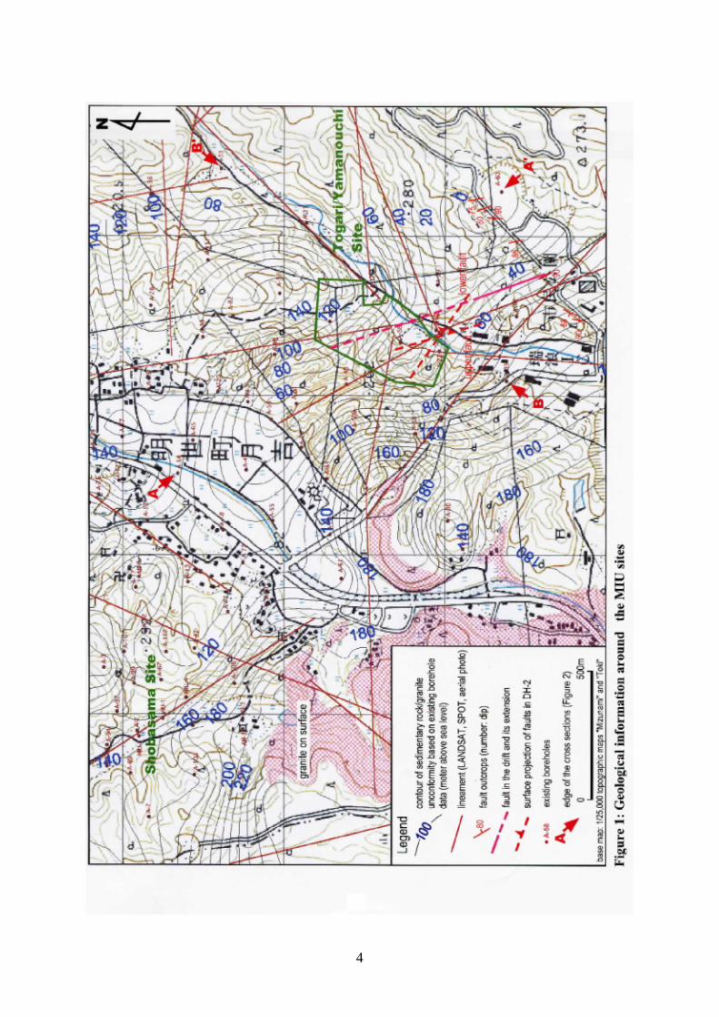
LIST OF FIGURES Figure 1: Geological information around the MIU sites 4
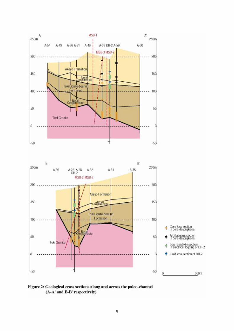
Figure 2: Geological cross sections along and across the paleo-channel 5
Figure 3: Geological information and borehole location 10
Figure 4: Test sequence of hydraulic packer tests 19
Figure 5: Predicted cross section along MSB-3 33
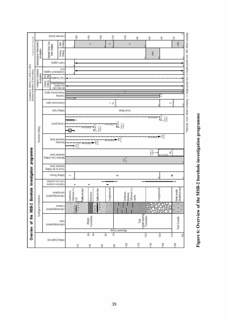
Figure 6: Overview of the investigation programme in MSB-2 39
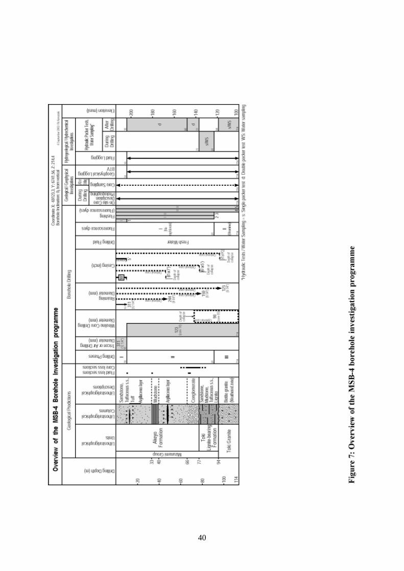
Figure 7: Overview of the investigation programme in MSB-4 40
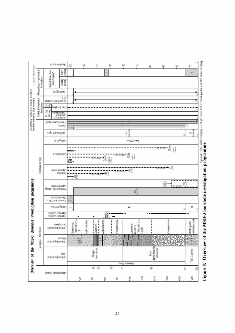
Figure 8: Overview of the investigation programme in MSB-3 41
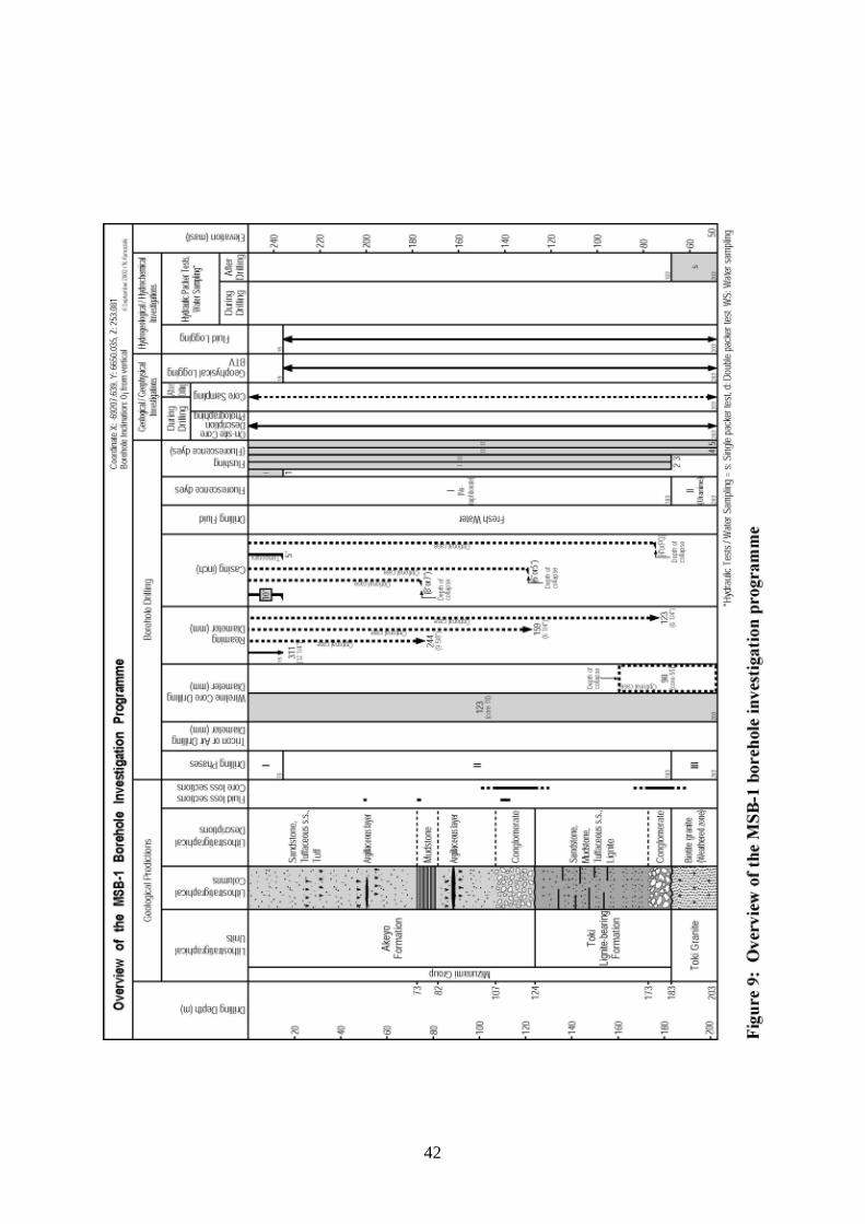
Figure 9: Overview of the investigation programme in MSB-1 42
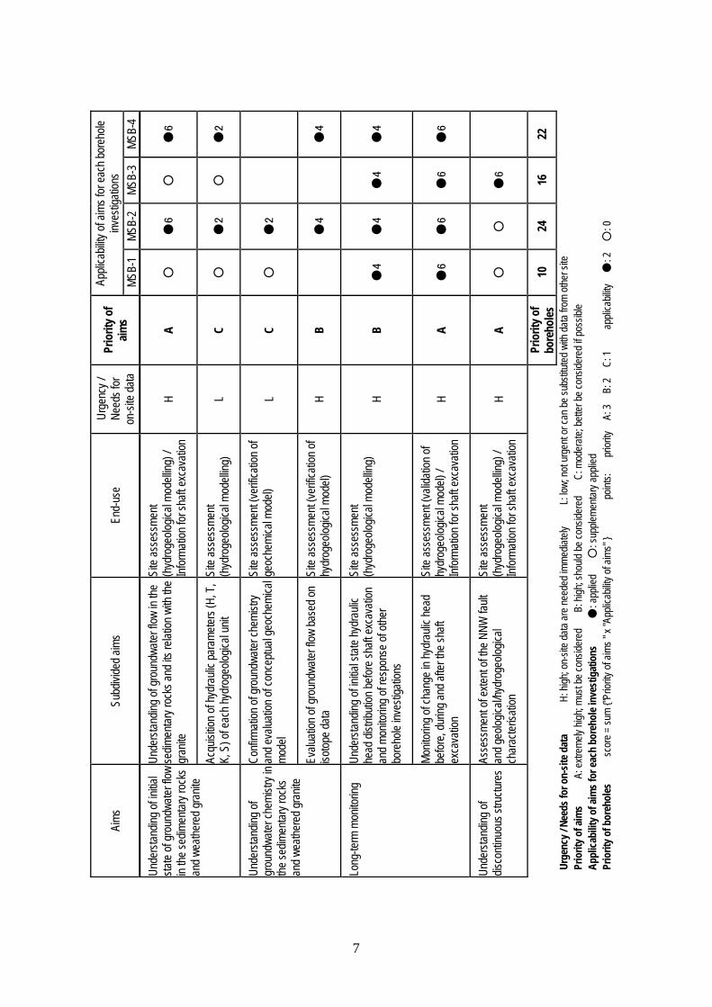
LIST OF TABLES Table 1: Aims and priority of borehole investigations 7
Table 2: Planned hydraulic packer tests (base case) 20
Table 3: Planned analytical work for geochemical investigations 24
Table 4: Planned analytical work for hydrochemical investigations 28
Table 5: Estimated depths of geological boundaries 32
Table 6: Optional cases of the investigation programme 44
Table 7: Schedule of the Shallow Borehole Investigation programme 45
Table 8: Budget for the Shallow Borehole Investigation programme 47
1
1 INTRODUCTION The MIU project has been conducted at the Shobasama site since 1997. JNC decided to shift the construction site for the underground research laboratory to the Mizunami city's property at Togari/Yamanouchi in 2001. The contract to lease the land was signed in January of 2002, and the investigations from surface have now started. In the revised general plan for the geoscientific research programme of the MIU project (JNC, 2002), investigations are conducted in three phases, Phase 1 surface-based investigations, Phase 2 during excavation of shafts and experimental tunnels and Phase 3 the underground operations. Overall objectives of the project are: • To develop basic techniques to investigate, analyse and evaluate the deep geological
environment, and • To develop basic engineering techniques for use in the deep underground.
Objectives of Phase 1, surface-based investigations are: • To construct a geological model based on the investigation from surface and understand
the deep geological environment before excavation of the shaft and experimental drifts, • To develop the detailed design and construction plan of the shaft and experimental drifts,
and • To develop scientific plans for Phase 2, investigations during excavation of the shaft and
experimental drifts. In the MIU Project and the Regional Hydrogeological Study (RHS), a large surface-based study surrounding the MIU, three scales of investigation are employed They are: • Regional scale (several 10km square), • Local scale (several km square), and • Block scale (several 100m square).
Investigations in the MIU project are, for the most part, performed at the block scale while those in the Regional Hydrogeological Study (RHS) project are performed at the regional and local scales. The Phase1 surface-based investigations are planned for completion by the end of 2004, while excavation of the main shaft is planned to start within the fiscal year of 2003. The Shallow Borehole Investigations are one of the first programmes, together with the reflection seismic survey and the re-investigation of borehole DH-2. The Shallow Borehole Investigations will target the shallow part of the site, from the sedimentary cover rocks to the upper part of the granite. The results will provide information for interpretation of the site, for other investigations, and also for planning later programmes such as borehole geophysics, cross-hole hydraulic tests, and borehole investigations in MIZ-1, DH-15 and 16. The plans for the Shallow Borehole Investigations are described in detail in the following sections.
2
2 PRESENT KNOWLEDGE AND HYPOTHESES ON THE GEOLOGICAL ENVIRONMENT As a first step, existing data relevant to groundwater flow around the Togari/Yamanouchi site were collected. The data comprise results from the earlier PNC uranium exploration programme, together with data from the Regional Hydrogeological Study, investigations in the Tono Mine and the MIU project so far. This information was supplemented by new reconnaissance geological mapping in and around the site. The collected information as of the end of March 2002 is summarised as follows. Topography • The site comprises small ridges and valleys derived by erosion of the large NNE-SSW
trending ridge in the west, and a narrow fluvial plain along the Hazama River in the east. Geology and structure (Figures 1 and 2) • The Cretaceous Toki granite is unconformably overlain by the generally flat lying
Miocene Mizunami Group (younging upwards from the Toki Lignite-bearing Formation to the Akeyo and Oidawara Formations). The Pliocene Seto Group unconformably overlies the Miocene units. These sedimentary formations are generally subhorizontal to gently south dipping, except for the basal part of Toki Lignite-bearing Formation where debris flows in a steep-sided paleo-channel are believed to occur. The upper part of Akeyo Formation outcrops around the site.
• A paleo-channel on the granite erosion surface is formed in a SE direction from the Tono Mine area via the Shobasama site to southwest of the Togari/Yamanouchi site.
• Thickness of the weathered zone, the top of the granite is about 1m in DH-2 and up to 20m in the other DH (RHS boreholes) and MIU boreholes where granite, is covered by sedimentary rocks.
• Basal conglomerate of the Toki Lignite-bearing Formation fills the above-mentioned paleo-channel to about 50 m thickness but is absent on the higher slopes on the sides of the channel. Basal conglomerate of Akeyo Formation ranges from 10 to 20 m thick.
• A few argillaceous layers, possibly similar to that in the Tono mine, are recognised near the base and upper part of Akeyo Formation in exploration boreholes A-58 and 59, and borehole BP-5 adjacent to the planned shaft. The layers are also defined as low resistivity sections in the electrical logging in DH-2.
• Based on past experience, core recovery is generally poor in the weathered granite and basal conglomerate of Toki Lignite-bearing Formation due to their highly weathered or unconsolidated, friable nature. The upper Akeyo Formation, to about 30m depth is also locally loose.
• Two steeply-dipping faults striking NNW and NW were intersected by DH-2 although surface expression of the faults has not yet been found.
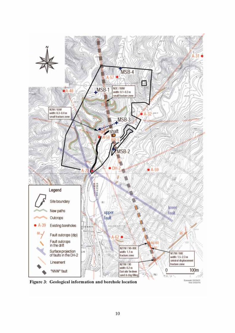
• A subvertical NNW trending fault, the "NNW fault", was observed in a nearby drift system in the Akeyo Formation and in a road cut to the southeast of the site. It comprises a 1.5 - 2.3 m wide highly fractured zone in the drift and a 0.2 m wide sand/clay-filled zone on the road cut. Its northern extension, if it is continuous, penetrates the centre of the site (Figure 3).
• N-S, NE, NNW and E-W trending lineaments are visible on satellite images and aerial photos of the site. Existence of two minor N-S trending fracture zones coincident with
3
the N07W trending lineament in the centre of site implies the existence of a fault with similar strike. No other fault or fracture zone has been found in the site.
Hydrogeology • Preliminary groundwater flow simulation suggests that the general flow direction in the
shallow part of site is from NE to SW, following the regional topographic gradient. • Conglomerates generally have higher hydraulic conductivity and the argillaceous layers
are lower conductivity compared to the other sedimentary rocks. The argillaceous layers in the Tono Mine are believed to cause artesian conditions in the lower strata.
• Fluid loss during drilling was recorded at loose sections in the upper part of the Akeyo Formation and its basal conglomerate in DH-2 and BP-5.
Hydrochemistry/Geochemistry • In the sedimentary rocks to 40-50m depth and in granite to 200 - 300 m depth,
groundwater is Na-Ca-HCO3 type, neutral (pH=7) and oxidizing (Eh= +300 ~ 0 mV), while in the deeper parts of these rocks, groundwater is Na-HCO3 type, weakly alkaline (pH= 9 ~ 10) and reducing (Eh= -300 ~ -400 mV).
• Dominant geochemical processes above the redox boundary depth are dissolution of calcite, feldspars and iron-bearing minerals such as biotite, while those below the boundary are ionic exchange and sulphate acid reduction.
• Groundwater north of the Toki River is Na-HCO3 type while the groundwater in the vicinity of the river is Na-Cl type (e.g. DH-12).
• C14 age of groundwater in the lower part of sedimentary rocks suggests vertical infiltration over several thousands of years, i.e. a long residence time.
Hypotheses Based on the above knowledge, the following hypotheses on the shallow geological environment of the site are made. • Groundwater flow as a whole trends from NE to SW following the regional topographic
gradient and is locally influenced by the basement topography (paleo-channel) and the conglomerate and argillaceous layers.
• Variations in the hydrogeochemical front, i.e., groundwater type, geochemical processes and redox front occur in the sedimentary rocks, assuming a similar geological setting to the Tono Mine and Shobasama site.
• The “NNW fault” extends to the centre of site, then is assumed to deviate north coincident with the N07W trending lineament. The fault extends into granite with the same or larger width. This fault may be a major potential water-conducting feature assuming that the fractured or friable internal structure is continuous at depth.
• Shaft excavation will cause drawdown of hydraulic head and geochemical front in the vicinity of the shaft. Na-Cl type groundwater may migrate from south (and deep underground?) and mix with existing groundwater at the site.
4
5
6
3 AIMS OF THE SHALLOW BOREHOLE INVESTIGATIONS AND THEIR PRIORITIES
Aims and application of results Based on the existing information and hypotheses, the aims of the Shallow Borehole Investigations were established as outlined below, and summarised in Table 1. 1. To understand the initial state of groundwater flow in the sedimentary rocks and weathered
granite to: a: Understand groundwater flow in the sedimentary rocks and the relationship with the
flow in the granite. This includes assessment of influence of the basement topography (paleo-channel), conglomerates and argillaceous layers on the local flow. The results provide a basis to construct hydrogeological models and also provide relevant information for the shaft excavation, in terms of expected geological conditions and response to excavation.
b: Acquire hydraulic parameters such as hydraulic head, transmissivity, conductivity and storativity of each hydrogeological unit. The results provide a basis to construct hydrogeological models.
2. To understand groundwater chemistry in the sedimentary rocks and weathered granite to: a: Confirm groundwater chemistry, geochemical processes and location of redox front
within the sedimentary rocks and evaluate existing conceptual geochemical model. The results consequently contribute to validation of the geochemical model.
b: Evaluate groundwater flow based on isotopic data. The results consequently contribute to validation of hydrogeological models.
3. To monitor hydraulic head continuously to: a: Understand initial state hydraulic head distribution before shaft excavation and to
monitor response from other borehole investigations. The results provide basis to construct hydrogeological models.
b: Monitor changes in hydraulic head before, during and after shaft excavation. The results contribute to validation of the hydrogeological models and also provide relevant information for shaft excavation.
4. To understand relevant discontinuities, i.e., structures in the site. This aim is described as to:
a: Assess existence and extent of the “NNW fault” in the site, and to characterise it geologically and hydrogeologically.
Prioritisation of the aims The aims were evaluated to provide a basis for determining location, layout and priority of the boreholes. Evaluation was made based on degree of contribution of results to the MIU project (i.e. number of items in the column "Applicability of aims"), and urgency of results or needs for on-site data (i.e. whether on-site data are needed immediately, or the results are not urgent or can be substituted with data from other sites). If the urgency for on-site data were low, the aim was ranked as C, the lowest priority. If the urgency of results or needs for on-site data is high and the degree of contribution of results is high (for example, contribution to shaft excavation), the aim is ranked as A, the highest priority. The rest are ranked as B, moderate priority. The results are shown in Table 1.
7
MSB-
4
●6
●2
●4
●4
●6
22
MSB-
3
○
○
●4
●6
●6
16
MSB-
2
●6
●2
●2
●4
●4
●6
○
24
Appli
cabil
ity of
aims
for e
ach b
oreh
ole
inves
tigati
ons
MSB-
1
○
○
○
●4
●6
○
10
Prio
rity o
f aim
s
A C C B B A A
Prio
rity o
f bo
reho
les
Urge
ncy /
Ne
eds f
or
on-si
te da
ta
H L L H H H H
End-
use
Site
asse
ssme
nt (h
ydro
geolo
gical
mode
lling)
/ Inf
orma
tion f
or sh
aft ex
cava
tion
Site
asse
ssme
nt (h
ydro
geolo
gical
mode
lling)
Site
asse
ssme
nt (ve
rifica
tion o
f ge
oche
mica
l mod
el)
Site
asse
ssme
nt (ve
rifica
tion o
f hy
drog
eolog
ical m
odel)
Site
asse
ssme
nt (h
ydro
geolo
gical
mode
lling)
Site
asse
ssme
nt (va
lidati
on of
hy
drog
eolog
ical m
odel)
/ Inf
orma
tion f
or sh
aft ex
cava
tion
Site
asse
ssme
nt (h
ydro
geolo
gical
mode
lling)
/ Inf
orma
tion f
or sh
aft ex
cava
tion
Subd
ivide
d aim
s
Unde
rstan
ding o
f gro
undw
ater f
low in
the
sedim
entar
y roc
ks an
d its
relat
ion w
ith th
e gr
anite
Acqu
isitio
n of h
ydra
ulic p
aram
eters
(H, T
, K,
S) o
f eac
h hyd
roge
ologic
al un
it
Confi
rmati
on of
grou
ndwa
ter ch
emist
ry an
d eva
luatio
n of c
once
ptual
geoc
hemi
cal
mode
l
Evalu
ation
of gr
ound
water
flow
base
d on
isotop
e data
Unde
rstan
ding o
f initia
l stat
e hyd
rauli
c he
ad di
stribu
tion b
efore
shaft
exca
vatio
n an
d mon
itorin
g of r
espo
nse o
f othe
r bo
reho
le inv
estig
ation
s
Monit
oring
of ch
ange
in hy
drau
lic he
ad
befor
e, du
ring a
nd af
ter th
e sha
ft ex
cava
tion
Asse
ssme
nt of
exten
t of th
e NNW
fault
an
d geo
logica
l/hyd
roge
ologic
al ch
arac
terisa
tion
Aims
Unde
rstan
ding o
f initia
l sta
te of
grou
ndwa
ter flo
w in
the se
dimen
tary r
ocks
an
d wea
there
d gra
nite
Unde
rstan
ding o
f gr
ound
water
chem
istry
in the
sedim
entar
y roc
ks
and w
eathe
red g
ranit
e
Long
-term
mon
itorin
g
Unde
rstan
ding o
f dis
conti
nuou
s stru
cture
s
Urg
ency
/ Nee
ds fo
r on-
site d
ata
H: h
igh; o
n-sit
e data
are n
eede
d imm
ediat
ely
L:
low; n
ot ur
gent
or ca
n be s
ubsti
tuted
with
data
from
other
site
P
riorit
y of a
ims
A: ex
treme
ly hig
h; mu
st be
cons
idere
d
B: hi
gh; s
hould
be co
nside
red
C:
mod
erate
; bett
er be
cons
idere
d if p
ossib
le A
pplic
abilit
y of a
ims f
or ea
ch b
oreh
ole i
nves
tigat
ions
●: a
pplie
d
○: s
upple
menta
ry ap
plied
P
riorit
y of b
oreh
oles
sco
re =
sum
{"Prio
rity of
aims
" x "
Appli
cabil
ity of
aims
" }
poin
ts:
prio
rity
A: 3
B: 2
C:
1
app
licab
ility
●: 2
○
: 0
8
4 LOCATION, LAYOUT AND PRIORITY OF BOREHOLES Location and layout of boreholes The following restrictions and requirements were considered during the planning of the location and layout of boreholes. Restrictions: • Budget for four vertical holes, total drilling length approximately 800m. • Boreholes must be within the site and cannot cross site boundaries. • Influence or impact on facility construction work should be minimized or avoided. • Flat or gently sloping land with good access is essential for drilling work.
Requirements: • From perspective of understanding of groundwater flow and long-term monitoring,
boreholes on the NE and SW sides of the site (minimum one per side) are required to confirm hydraulic properties along the general flow direction.
• From geochemical perspective, thicker sedimentary cover and lower water table level (i.e. on the hill) are required to definitely intersect the redox boundary in sedimentary rock. Absence of faulting is preferred for easier interpretation of results.
• Boreholes should not be too close to the shaft nor to each other for monitoring purposes. • An inclined hole is required to intersect the subvertical NNW fault.
Location and layout of the four boreholes, as shown in Figure 3, were determined taking the prioritised aims and the above restrictions and requirements into account. "MSB" before the borehole number stands for MIU Shallow Borehole. Aims and priorities of boreholes Application of the prioritised aims of the investigations for each borehole, in other words the main task of each borehole, was confirmed and priority of boreholes was quantitatively determined to optimise the investigation programme (e.g. order and detailed specifications of borehole drilling and investigations). Priority of boreholes was determined by the numerical ranking of each borehole based on the following calculation. The aims were assigned integer values based on their priority (3, 2 or 1) and their applicability to the research objectives (2 or 0) for each borehole. For each aim, the priority was multiplied by the applicability. The sum of these multiplications, for each borehole, determined the priority of the borehole (see Table 1). The priority and aims for each borehole are described below. The borehole numbers used do not represent the priority that has been assigned in the later planning stage, as discussed in this section. Rather they represent the original numbering system and have not been changed to maintain consistency with the original planning documents.
MSB-2: a vertical hole to understand and monitor hydrogeological and geochemical
conditions downstream of both the regional groundwater flow and the paleo-channel.
MSB-4: a vertical hole to understand and monitor hydrogeological and geochemical conditions on the upstream side of the regional groundwater flow field.
MSB-3: an inclined hole 20 degrees from vertical to characterise the "NNW fault" within

9
the sedimentary rocks, also to monitor hydraulic condition. MSB-1: a vertical hole to understand and monitor hydrogeological conditions in the
upstream side of paleo-channel and, to understand geochemical condition around the redox front.
10
11
5 DETAILS OF THE SHALLOW BOREHOLE INVESTIGATIONS The following subsections (5.1 to 5.7) discuss details of the "base case" programme in each field of investigation. The procedure for the "base case" investigation campaign is described in the section 6.1.1. 5.1 Borehole Drilling The shallow borehole investigations are the first borehole investigation programme in the Togari/Yamanouchi site. Because the boreholes target weakly consolidated sedimentary cover rocks and friable weathered granite, full core recovery and stable borehole condition may be difficult. Experience in the previous MIU and RHS borehole investigations should be fully applied. All depths are given in metres along borehole (mabh) 5.1.1 Aims • Full core recovery for geological, hydrogeological, hydrochemical and geochemical
investigations. • To provide suitable locations for downhole investigations such as hydraulic packer tests,
groundwater sampling and borehole logging. 5.1.2 Methodology The four boreholes will be drilled with two rigs. It is possible to drill two holes simultaneously. Each borehole is drilled in three phases, phase I from surface through the surficial material to bedrock, phase II to above or immediately below the unconformity between sedimentary rocks and granite, and the phase III to below the bottom of the weathered zone of granite. Details are discussed in Section 6. The following on-site activities are planned. Casing and cementing After PQ wireline core drilling of the soil and friable top of the Mizunami Group from surface to a depth of about 10-15 mabh, the boreholes are reamed to a diameter of 12 ¼ inches (311 mm). In MSB-3, a tricone bit or air hammer drilling will be used in this part because need for core is low. Ten inch (254 mm) casing pipes are then installed and fixed by full hole cementing. Dredging and flushing of the borehole are performed after cementing. For further drilling, 5 inch (127 mm) temporary casing is installed to the bottom of the casing. Coring PQ wireline core drilling is performed from surface to the final depth, 5 m below the weathered zone of granite to provide space for the borehole logging equipment. A triple-barrel corer with an acrylic innermost tube is employed for full core recovery. For all PQ drilling, the borehole diameter is 123 mm and the core diameter is about 80 mm. Drilling/flushing fluid Fresh water will be used for all drilling and flushing operations. The fresh water will be tagged with different fluorescent dyes, depending on the rock being drilled, to allow
12
identification of drilling fluid during the hydrochemical investigations. That is, to try to ensure uncontaminated formation water, the baseline condition, is sampled for the characterization work. Two drilling fluid types will be used: drilling fluid (I), fresh water tagged with Na-naphtionate and drilling fluid (II), fresh water tagged with uranine. Both dyes are fluorescent. Drilling fluid (I) will be used only in the Mizunami Group. Drilling fluid (II) will be used only in the final drilling phase, into the granite. This will allow an assessment of the connectivity between the sedimentary rocks and the upper part of the granite to be made. No other chemicals or additives are used for geochemical/hydrochemical reasons. Monitoring Drilling data such as drilling rate, bit revolution, bit load, torque, pumping pressure, rate of water supply and return and any fluid volumes lost or gained are continuously monitored to complement geological and hydrogeological investigations. A single shot hole deviation survey and callipers logging are performed after every 30m of drilling. Borehole protection In case significant drilling fluid loss in the Mizunami Group makes continued drilling impossible, that is when more than 50% of drilling fluid is lost and preparation of additional drilling fluid cannot maintain drilling fluid volumes due to the loss, hydraulic testing of the zone, if feasible, will be done. Then the zone will be sealed with LCM (lost circulation material). If loss occurs in the granite, no plugging will be performed. Effort to reach the final depth will be made. In the event of significant borehole collapse above the basal conglomerate of the Toki Lignite-bearing Formation, protection with casing and full-hole cementing is possible (entire 8" or 7", and 6" or 5" diameters). When it occurs within the basal conglomerate of Toki Lignite-bearing Formation, 4 inch casing is installed or PQ rods are used as casing to the depths of collapse and fixed by full-hole cementing; then drilling is continued with downsized spec using HQ bit. In case of a significant borehole collapse in the granite, drilling is shut down and all planned post-drilling investigations are performed. All possible on-site investigations to the site of fluid loss and/or collapse should be completed before any borehole protection is made. In case of significant collapse with significant fluid loss, the treatment is identical to the case of borehole collapse. 4.1.3 Reporting Daily reportⅠ (daily at 8.30) Status of the field work (drilling length, water level and tests performed, etc.) is reported by fax. Daily report Ⅱ(to be supplied to JNC the next morning) Time of drilling, personnel, activities undertaken, drilling length, lengths and dimensions of rods and casing pipes used, result of deviation survey, bit life, details of machinery used, consumption of supplies and anything abnormal or unexpected are reported promptly. Final report (by the end of the contract period) A complete record of drilling is reported in detail with logs of drilling data.
13
5.2 Geological Investigations The goals of geological investigations are to acquire geological and structural information and to identify high and low permeability structures in the shallow geological environment. 5.2.1 Aims • To locate and characterise potentially hydrogeologically relevant geology and structures
such as the weathered zone and the paleo-channel at the top of granite, basal conglomerate and argillaceous impermeable layers in sedimentary rocks.
• To characterise geologically identified potential water-conducting features in the sedimentary rocks and in the upper part of granite.
• To acquire fracture data, the spatial distribution, geometry and mineralogy for geochemical investigations.
• To check and improve the existing conceptual geological model, with emphasis on the "NNW fault".
5.2.2 Methods The methods to be employed are as follows:
Core description: detailed information on lithology, alteration and fractures Core photography: visual geological information (i.e. core images)
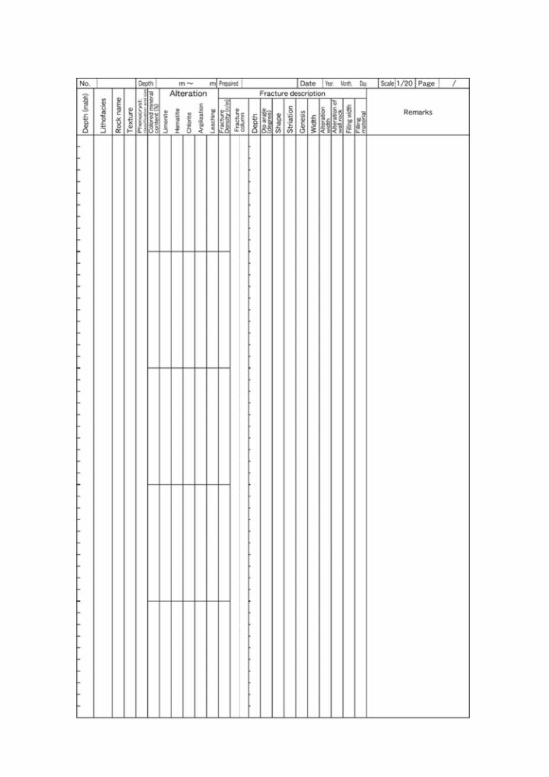
5.2.3 Planned field work Core handling (by contractor) After cores are extracted from the acrylic inner core barrel, these are under the full care and responsibility of the contract field geologist. A reference line is drawn on the core, as continuously as possible from the previous core run, to orient cores sequentially. Cores are cut basically every metre along borehole axis except where important feature straddle the planned cut. In that case the core is cut above and below the feature, then regular cutting is resumed. Cores are put into specially made core boxes that can be sealed to minimize alteration by oxidation and drying. The cores are surveyed with a scintillometer to predict the occurrence of basal conglomerate and unconformity, and to identify targets for geochemical sampling. That is because the mineralization in this area occurs generally in the arkosic sandstone immediately above the conglomerate, or where the conglomerate is absent, above the unconformity. After the core description and photography, the lid is sealed and the air in the box is exchanged with inactive gas (Ar). The entire core from MSB-2 and 4, and anomalous parts identified by the gamma survey in MSB-3 and 1 are potential targets for geochemical sampling. Therefore two hours limit was set from recovery to sealing in these cores. On-site core description and photography (by contractor) The cores are described fully at 1/20 scale by a contractor according to JNC’s manual (Appendix II). The following items are included in the description; drilling length along borehole axis, lithofacies (log), rock type, texture, clastic particle and phenocryst (mineral, gravel, diameter and shape), mafic mineral content, alteration, fracture density, location and

14
dip of fractures (log), shape of fractures, structure on fracture plane, nature of alteration products along fractures, width of fractures and mineralogy of fracture filling materials. Depths where the core is cut for storage are also recorded. Borehole profiles including this information will provide basis for other investigations. Images of all core are taken using a camera to preserve visual geological and structural information. All images include a scale and a colour chart. Each image includes up to two, 1m long (or less) lengths of core. 5.2.4 Reporting Quick-look report (daily at 9.00 and 17.00) Outline of lithofacies, alteration and geological structure on the cores drilled since the last report is reported by telephone. Information on any anomalies and/or unexpected events encountered during drilling is also given. Daily report (on the morning following the day covered by the report) A summary of lithofacies, alteration and geological structures based upon the on-site core description is reported with appended description sheets filled in the previous day. Details of any anomalies and/or unexpected events encountered during drilling are described in the sheets. Summary report (within a week after each 100m of drilling has been completed) A summary of lithofacies, alteration and geological structure including defined anomalies and/or events is reported with a geological log at 1/500 scale. All description sheets covering the interval are also submitted. Digitised numerical data (e.g. fracture density) are also supplied. Final report (by the end of contract period) A detailed geological description is reported with a full data set in a section of the final report. Full details of all methods employed, operating conditions of equipment, relevant detection limits and precision are described. Details are also given of anything unexpected that occurred during drilling.
15
5.3 Geophysical Investigations Geophysical logging and borehole TV (BTV) provide continuous and quantitative information fundamental to characterise both water-conducting and impermeable features. In the borehole investigation programme, it is therefore planned to conduct a series of geophysical investigations. 5.3.1 Aims • To identify possible water-conducting features and impermeable argillaceous layers. • To acquire information on the orientation and geometry of geological discontinuities. • To acquire geophysical properties continuously to support the geological and
hydrochemical modelling. • To characterise in situ neutron flux production for hydrochemical interpretations.
5.3.2 Methods A series of geophysical investigations are carried out by the following methods: 1. Petrophysical logging
Electrical: apparent resistivity of surrounding rock Micro electrical: apparent resistivity of the borehole wall Natural gamma: gamma rays from radioactive elements in the rocks Gamma spectrum: gamma spectrum from radioactive elements (K,U,Th) in rocks Neutron: thermal neutron correlated with total porosity around the borehole Density: decayed gamma rays correlated with apparent density Acoustic: P-wave velocity
2. Geotechnical logging
X-Y calliper: borehole diameters in two orthogonal directions Deviation: orientation and inclination of borehole
3. Borehole TV (BTV: digital scanning of the borehole wall) 5.3.3 Planned investigations Geophysical logging and BTV are performed, which can provide information to select test intervals for downhole investigations such as hydraulic packer tests. The location, orientation, width, shape and appearance of geological discontinuities such as fractures, fracture zones, faults, lithological boundaries and impermeable layers are identified. The distribution of the structure system is defined by data analysis. Water-conducting features may be proposed from anomalies on the geophysical logs and BTV, and by comparing these logs with other geological and hydrogeological information.

16
5.3.4 Reporting 5.3.4.1 Geophysical logging Prompt report (within 1 day after the investigation has been completed) Each of the logs is submitted. Any anomalies and/or unexpected events encountered during the field work are also documented. Interim report (within 3 days after the investigation has been completed) A sheet with all profiles at the same scale is submitted. Raw digital data in Microsoft Excel™ files are also submitted to JNC as soon as possible. Details of the anomalies and/or unexpected events are reported. Preliminary interpretation of results is also reported. Final report (by the end of the contract period) The report should include final interpretations of results (e.g. any anomalies and/or unexpected events) and the full data set. Data are in a format compatible with the Land Mark™ software for modelling. Full details of all methods employed, operating conditions of equipment, relevant detection limits and precision are described. 5.3.4.2 Borehole TV Prompt report (within 1 day after the investigation has been completed) Pictures are submitted on a videotape. Digitised images in BIPS™ image files to be used for analysis by computer (Borehole Image Processing System program) are also submitted to JNC as soon as possible. Details of any anomalies and/or unexpected events encountered during field work are also given. Interim report (within 2 months after the investigation has been completed) The locations, orientations, widths, shapes and appearance of geological discontinuities such as fractures, fracture zones, faults, flow structures, lithological boundaries and veins are identified. The structures can be compared with those identified on the core and the two sets of data should be matched as closely as possible. Results are submitted digitally in Microsoft Excel™ files. Preliminary interpretation of results is also reported. Final report (by the end of the contract period) Final interpretations of results (e.g. details of identified discontinuities) and full data sets are reported. Full details of all methods employed, operating conditions of equipment, relevant detection limits and precision are described.
17
5.4 Hydrogeological Investigations Previous investigations performed in the borehole DH-2 have provided the following information on the hydrogeological characteristics of the sedimentary formation and granite in the vicinity of the Togari/Yamanouchi site: • Some water-conducting features have been inferred from the anomalies in the
temperature log (in the Akeyo Formation). • Most hydraulic conductivity values obtained in the sedimentary formations indicate
higher than 10-7 m/sec. • Hydraulic heads in the upper part of the Akeyo Formation have higher values than other
parts of the sedimentary formation. Further hydraulic information is needed for the sedimentary formations and the granite. Therefore, it is also planned to monitor hydraulic pressure and take groundwater samples after the borehole investigations. 5.4.1 Aim • To obtain basic and good quality data on the transmissivity, hydraulic conductivity and
hydraulic heads in the sedimentary formations and weathered granite. 5.4.2 Methods Fluid logging and hydraulic packer tests are planned. The methods to be employed are as follows: 1. Fluid logging • Spinner flowmeter logging: continuous measurement of flow velocity • Electromagnetic flowmeter logging: continuous measurement of flow velocity • Heat pulse flowmeter logging: batch measurement of flow rate • Temperature logging: continuous measurement of temperature
2. Hydraulic tests • Pulse test: low to very low transmissivity • Slug test: average to low transmissivity • Pumping test: average to high transmissivity
18
5.4.3 Planned field work The sequence of field work is described below and in Table 2. 5.4.3.1 Work during drilling Single packer hydraulic tests (by contractor) Single packer hydraulic tests with water sampling are planned above the unconformity in MSB-2 and 4 to acquire hydraulic and hydrochemical data solely from the sedimentary rocks, and distinct from the granite. One or more test methods will be selected, depending on the expected transmissivity, the time available for testing and the applicable equipment (Figure 4). Initially, pulse or slug tests will be conducted, by withdrawal, to select the most appropriate testing method to apply. The selection is based on the rate of pressure recovery to its initial state or to extrapolate to the initial state. If a pumping test is possible as the main or diagnostic phase, pulse or slug tests are conducted first to determine appropriate pumping rates for the constant flow rate tests. Constant flow rate or constant pressure tests, followed by pressure recovery tests are then carried out. If groundwater is sampled during pumping, it is necessary to maintain pumping rates as low as possible to minimise the possibility of cross flow between formations. Flow rates and pressure above and below the test interval are monitored continuously during the pumping test. Finally pulse tests are conducted to check compressibility and hydraulic condition before and after the main phase of the test. 5.4.3.2 Work after drilling Single packer hydraulic tests (by contractor) Single packer or optional double packer hydraulic tests are planned in the weathered granite in all boreholes. The intent is to acquire hydraulic data from the weathered granite in all boreholes, and to assess potential effectiveness of MP system packers for long-term monitoring. Hydrochemical data will be acquired by water sampling during pumping only in MSB-2 and 4 (see Section 3 and Table 1 for details). The hydraulic tests and water sampling are conducted immediately after drilling in MSB-2 and 4 to minimise contamination of drilling fluid to the formation water. On the other hand, the hydraulic tests are performed after the geophysical/fluid logging to ensure the packer location and to save time for preparation. Test procedure is same as that of single packer hydraulic tests during drilling, discussed in the previous section. Fluid logging (by contractor) Different flow meter techniques are employed to identify water-conducting features. Spinner, electromagnetic and heat-pulse flowmeter logging in steady and pumping states are performed to identify inflow/outflow points. Heat pulse flowmeter logging is conducted to estimate flow rate at each inflow/outflow point. Conventional temperature logging is also performed to determine the inflow/outflow points. Anomalies on the profile suggest locations of the water-conducting features and complement the geological and hydrogeological interpretations.
19
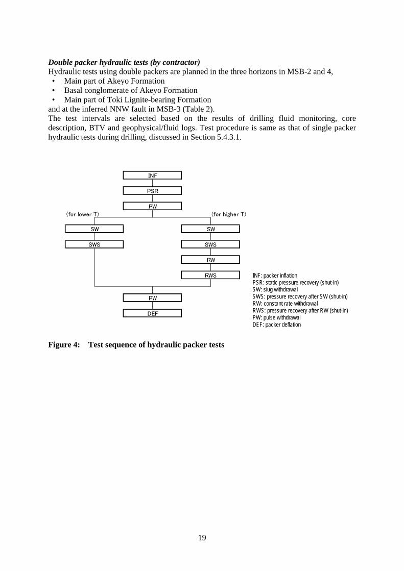
Double packer hydraulic tests (by contractor) Hydraulic tests using double packers are planned in the three horizons in MSB-2 and 4, • Main part of Akeyo Formation • Basal conglomerate of Akeyo Formation • Main part of Toki Lignite-bearing Formation
and at the inferred NNW fault in MSB-3 (Table 2). The test intervals are selected based on the results of drilling fluid monitoring, core description, BTV and geophysical/fluid logs. Test procedure is same as that of single packer hydraulic tests during drilling, discussed in Section 5.4.3.1. Figure 4: Test sequence of hydraulic packer tests
(for lower T) (for higher T)
INF
PSR
PW
SW
DEF
SWS
SW
SWS
RW
RWS
PW
INF: packer inflation PSR: static pressure recovery (shut-in) SW: slug withdrawal SWS: pressure recovery after SW (shut-in) RW: constant rate withdrawal RWS: pressure recovery after RW (shut-in) PW: pulse withdrawal DEF: packer deflation
20
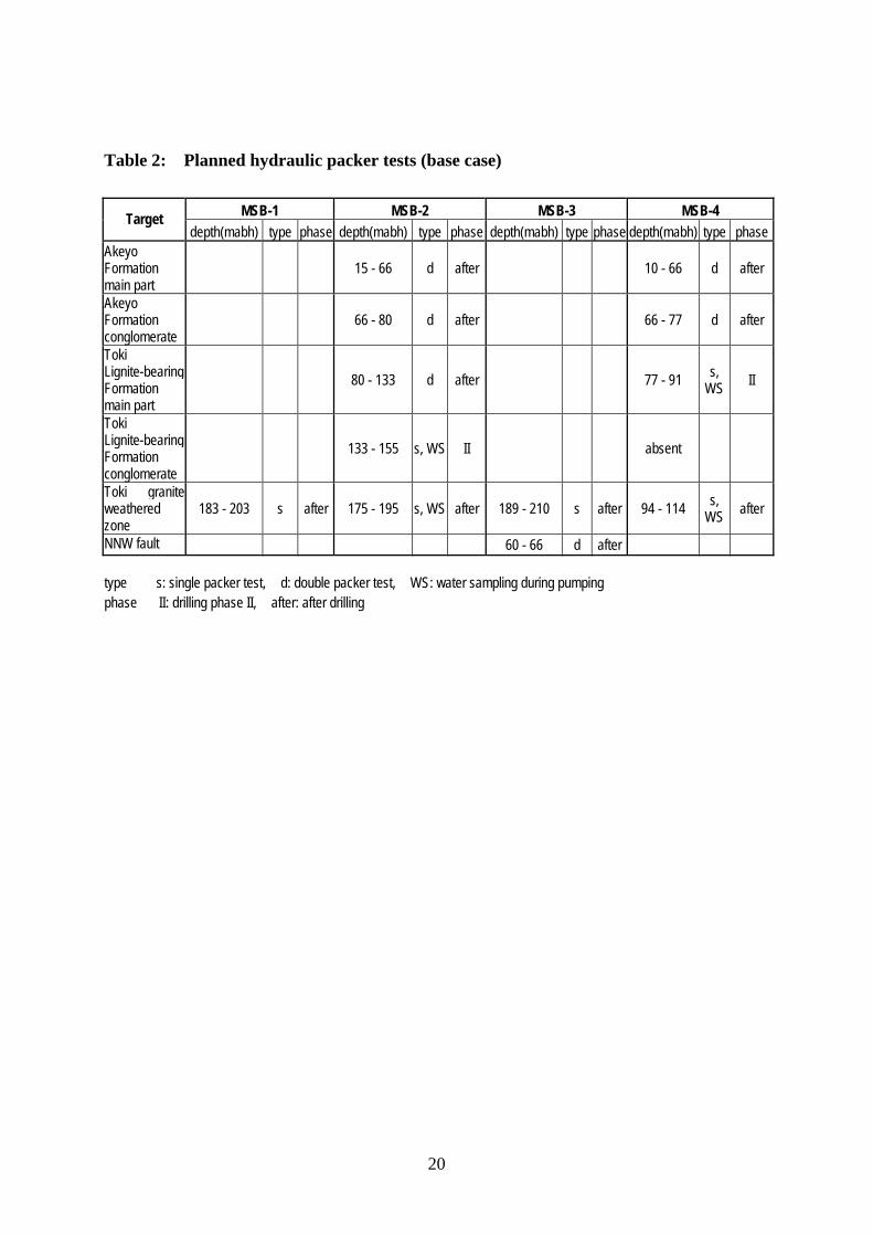
Table 2: Planned hydraulic packer tests (base case)
MSB-1 MSB-2 MSB-3 MSB-4 Target depth(mabh) type phase depth(mabh) type phase depth(mabh) type phase depth(mabh) type phase
Akeyo Formation main part
15 - 66 d after 10 - 66 d after
Akeyo Formation conglomerate
66 - 80 d after 66 - 77 d after
Toki Lignite-bearing Formation main part
80 - 133 d after 77 - 91 s, WS II
Toki Lignite-bearing Formation conglomerate
133 - 155 s, WS II absent
Toki graniteweathered zone
183 - 203 s after 175 - 195 s, WS after 189 - 210 s after 94 - 114 s, WS after
NNW fault 60 - 66 d after type s: single packer test, d: double packer test, WS: water sampling during pumping phase II: drilling phase II, after: after drilling
21
5.4.4 Reporting Prompt reports 1. Fluid logging (immediately after the investigation has been completed) Results of the fluid logging are reported together with the geophysical and geological logs. Information on any anomalies and/or unexpected events along the borehole is also reported. 2. Hydraulic packer tests (immediately after each investigation has been completed) Results of the hydraulic packer tests are reported with the following information:
• Objectives and employed techniques • Geology of test intervals • Test interval (upper/lower/midpoint depths, length and volume of packed-off interval,
pumping rate, etc.) • Borehole and tubing radius • Water level in annulus (in mabh) • Inflation pressure of packers (pressures in annulus and test interval) • Time of test start/end • Test results with detection limits and precision (hydraulic head, plotted data, analytical
method used, result of curve matching and transmissivity and hydraulic conductivity) • Short comments on the tests (including details of anything abnormal or unexpected)
JNC staff will check the quality of the data together with the test techniques selected. Summary report (within a week after each campaign has been completed) A summary of the hydraulic packer tests performed including transmissivity and/or hydraulic conductivity and hydraulic head with depth is reported together with the geological log. Comments on the hydraulic characteristics of the test intervals are also reported. Final report (by the end of contract period) All results are reported with full data sets. Full details of all methods employed, operating conditions of equipment, relevant detection limits and precision are described. Details are also given of anything unexpected that occurred during the investigations.
22
5.5 GEOCHEMICAL INVESTIGATIONS Geochemical investigations are performed on the core (rock mass, filling materials, alteration products) mainly from MSB-2 and 4, the geochemical and hydrochemical boreholes. The groundwater chemistry investigations are described in chapter 5.6. The Togari/Yamanouchi site is located at the eastern margin of the Tsukiyoshi uranium deposit. The deposit occurs in the downstream part of a paleo-channel formed on the granite erosion surface. Previous studies in the Tono mine area, in the middle part of the paleo-channel, confirmed the following geochemical conditions: • Redox front (iron oxy-hydroxide / hydrogen sulphide and ferrous iron) at 30-60 mabh. • Microbial reducers, denitrifying bacteria or sulphate reducing bacteria, occur at these
depths. • Low Eh (<-360 mV) of groundwater in deeper sedimentary rocks. • Dominant redox reactions: weathering of (iron, sulphur)-bearing minerals and microbial
reduction. Similar conditions are estimated in the Togari/Yamanouchi site because of similarity in the geological setting. This hypothesis will be evaluated in the geochemical investigations. 5.5.1 Aims • To estimate the chemical (pH-Eh) buffering capacities of the sedimentary rocks.
5.5.2 Methods Core observation: general mineralogical information Optical microscopy: detailed mineralogical information Modal analysis: mineral composition (%) X-ray diffractometry: mineral composition SEM examination: microtexture of minerals EPMA analysis: chemical composition of minerals Standard chemical analyses: chemical composition Standard isotopic analyses: isotopic composition C/N Corder analyses: organic composition
23
5.5.3 Planned field work Core sampling (by contractor / in house) Samples for laboratory work are taken based on information from previous investigations. 5.5.4 Planned laboratory work Planned analytical work in the laboratory is described below and on Table 3. Mineralogical and geochemical characterisation (by contractor) Standard microscopic observation and conventional modal analysis (e.g. point-counting) are conducted on rock thin sections to determine petrological and mineralogical characteristics of the sedimentary rocks and granite. Major chemical components in the same samples are analysed by XRF and wet chemical methods. The aims of these analyses are to provide geochemical data for interpreting water-rock interactions. Analysis of pH-Eh buffer capacity (by individual contractor and in house) The following program is performed to evaluate the pH-Eh buffering capacity in the water-mineral-microbial system that has helped to maintain reducing conditions around the uranium deposit. 1) Determine the quantity of reducing minerals such as pyrite and biotite and oxidant such as
evaporitic sulphate (Optical observation, IC, Isotope MS). 2) Identify weathering of biotite (XRD, EPMA). 3) Characterize the nature and crystallinity of Fe(III)-oxyhydroxides (XRD, EPMA,
SEM-EDS). 4) Deduction of the redox environment from in-situ Eh measurements together with
observations of dissolution features on the surfaces of silicate minerals, pyrite and calcite (SEM-EDS).
5) Fe and Mn concentrations in authigenic calcites (EPMA). 6) Characterization of condensed and dissolved forms of organic carbon (C/N Corder,
GC-MS, Reflected light petrography) 7) Clarification of microbial redox process and its regulation mechanism involving
redox-sensitive elements (Isotope MS)
24
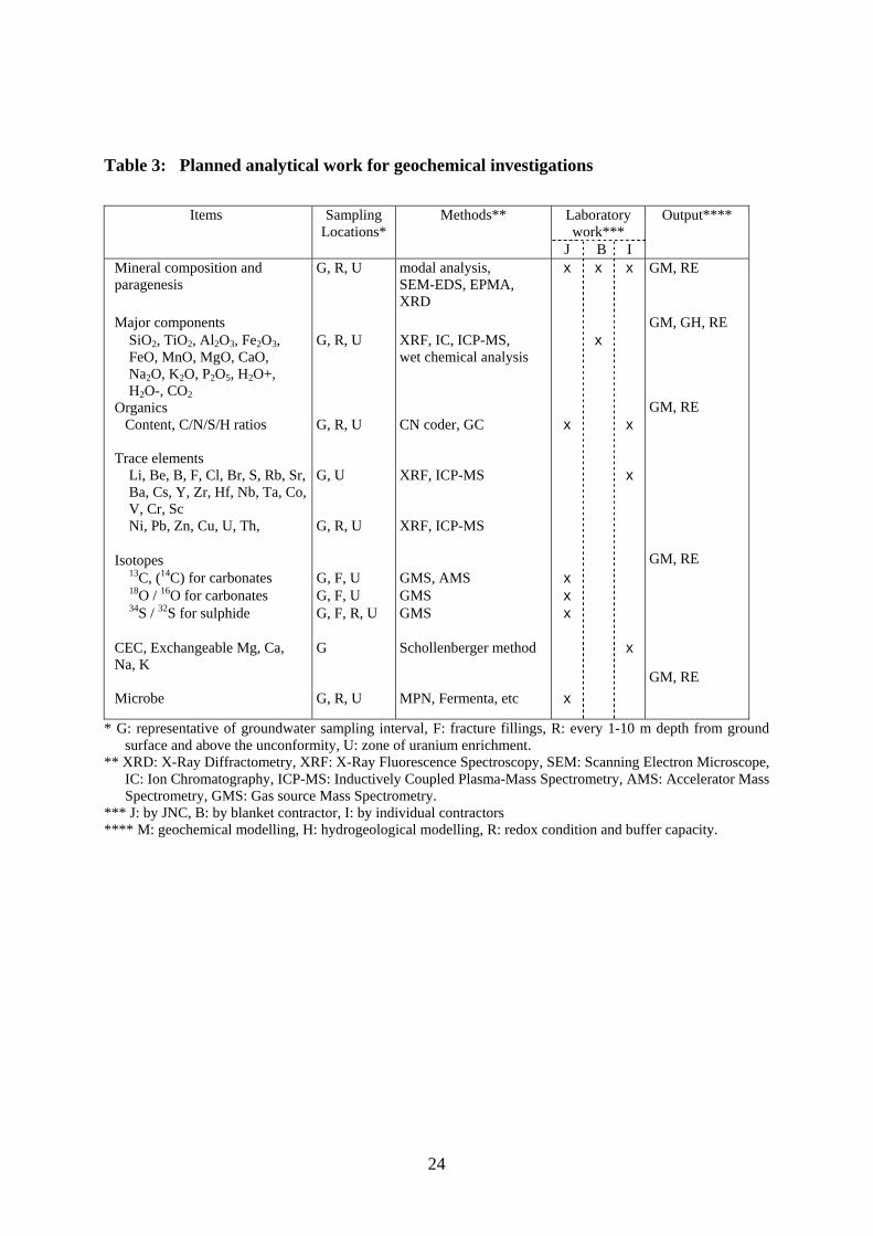
Table 3: Planned analytical work for geochemical investigations
Items Sampling Locations*
Methods** Laboratory work***
Output****
J B I Mineral composition and paragenesis
G, R, U
modal analysis, SEM-EDS, EPMA, XRD
x x x GM, RE
Major components SiO2, TiO2, Al2O3, Fe2O3, FeO, MnO, MgO, CaO, Na2O, K2O, P2O5, H2O+, H2O-, CO2
G, R, U XRF, IC, ICP-MS, wet chemical analysis
x
Organics Content, C/N/S/H ratios
Trace elements
G, R, U
CN coder, GC
x
x
Li, Be, B, F, Cl, Br, S, Rb, Sr, Ba, Cs, Y, Zr, Hf, Nb, Ta, Co, V, Cr, Sc Ni, Pb, Zn, Cu, U, Th,
G, U G, R, U
XRF, ICP-MS XRF, ICP-MS
x
Isotopes
13C, (14C) for carbonates G, F, U GMS, AMS x 18O / 16O for carbonates G, F, U GMS x 34S / 32S for sulphide G, F, R, U GMS x
CEC, Exchangeable Mg, Ca, Na, K
Microbe
G G, R, U
Schollenberger method MPN, Fermenta, etc
x
x
GM, GH, RE GM, RE GM, RE GM, RE
* G: representative of groundwater sampling interval, F: fracture fillings, R: every 1-10 m depth from ground surface and above the unconformity, U: zone of uranium enrichment.
** XRD: X-Ray Diffractometry, XRF: X-Ray Fluorescence Spectroscopy, SEM: Scanning Electron Microscope, IC: Ion Chromatography, ICP-MS: Inductively Coupled Plasma-Mass Spectrometry, AMS: Accelerator Mass Spectrometry, GMS: Gas source Mass Spectrometry.
*** J: by JNC, B: by blanket contractor, I: by individual contractors **** M: geochemical modelling, H: hydrogeological modelling, R: redox condition and buffer capacity.
25
5.5.5 Reporting 5.5.5.1 Reporting by contractor Prompt report (immediately after the investigation has been completed) Raw data are reported immediately after each phase of the investigation has been completed. Data quality is then checked by JNC. Final report (by the end of contract period) All results are reported with full data sets. Full details of all methods employed, operating conditions of equipment, relevant detection limits and precision are described. Details are also given of anything unexpected that occurred during the laboratory work. 5.5.5.2 Reporting by JNC The following geochemical issues are reported by JNC. The geochemical aspects related to hydrochemistry are discussed in the reports described in the next section. Chemical buffer capacity in the sedimentary rocks (1) Location of redox fronts around the uranium deposit. (2) The pH-Eh buffer processes in the water-mineral-microbial system. (3) Quantitative estimation of inorganic/biochemical buffer capacities.
26
5.6 HYDROCHEMICAL INVESTIGATIONS Hydrochemical properties in the Togari/Yamanouchi site are assumed to be similar to those in the Tono mine area because of their similar geological settings. The hydrochemical characteristics of the Tono mine area are summarised below. • Na + and HCO3
- increase and Ca 2+ decreases with depth. • Calcite dissolution and ion exchange between water - clay minerals control chemical
evolution of ground water in shallower sedimentary rocks. • Low Eh (<-360 mV) of groundwater in deeper sedimentary rocks. • 14 C age of groundwater in the lower part of sedimentary rocks suggests, a) vertical
infiltration through the sedimentary rocks over several thousand years and long residence time, or b) long distance migration along the unconformity. The flow rate (10-102mm/yr) calculated from relative 14 C ages (4-19 ka) are similar to those estimated by computer simulation using hydraulic pressure and conductivity data.
5.6.1 Aims • To verify the qualitative groundwater evolution model which has been developed for the
region in and around the Tono Mine and construct a quantitative groundwater evolution model.
• To infer the initial hydraulic condition around the shaft location. • To determine the depth profile of redox properties and estimate the redox buffering
capacity. • To obtain information to evaluate uncertainties in the geochemical interpretation of the
site (e.g. representativity of hydrochemical data obtained). • To obtain information on the residence times of groundwater in the sedimentary rocks
and upper part of granite. 5.6.2 Methods Groundwater sampling and subsequent analytical work are planned on the MIU site and in the laboratory. The methods to be employed are as follows. On site • Drilling fluid preparation: fresh water plus tracer prepared for quantitative
hydrochemical investigations • Drilling fluid analyses: during drilling to maintain desired fluorescent dye
concentration in drilling fluid • Drilling fluid analyses: during pumping to assess groundwater
contamination • Standard chemical analyses: drilling fluid and groundwater chemistry
In the laboratory • Comprehensive chemical analyses: drilling fluid and groundwater chemistries • Standard isotopic analyses: isotopic composition, origin and residence time of
groundwater • Gas analyses: redox conditions, recharge temperature, origin and
residence time of groundwater • Colloids/organics/microbes studies: population and role
27
5.6.3 Planned field work Drilling fluid preparation (in house) Fluorescent dyes are added to tag the drilling fluid for quantitative determination of the degree of drilling fluid contamination of the groundwater samples. The drilling fluid is mixed in a separate tank from an in-line fluid reservoir. After mixing, a reference sample of drilling fluid is stored. Fluorescent dyes selected based on laboratory tests are, (I) Na-naphtionate for use in the sedimentary formations and (II) uranine for use in the granite. The concentrations of dye in the drilling fluid are calculated considering the detection limits of the fluorescent dyes and the targeted maximum drilling fluid contamination in groundwater of 1%, to ensure high quality groundwater samples. Monitoring of drilling fluid during drilling (by contractor) The general analytical programme is shown in Table 4. Fluorescent dye concentrations in the drilling fluids are checked simultaneously with the other monitoring parameters. Major chemical constituents, isotopic compositions and fluorescent dye concentrations are determined at the site or in the off-site laboratory. Physico-chemical parameters are measured after MP system installation.
• Drilling fluid analyses: during drilling to maintain desired fluorescent dye
concentration in drilling fluid • Drilling fluid analyses: during pumping to assess groundwater
contamination reduction as borehole is flushed • Standard chemical analyses: drilling fluid and groundwater chemistry
Groundwater sampling combined with hydraulic tests (by contractor) Water samples are taken during pumping tests in the bottom horizons of the sedimentary rocks and the weathered granite in MSB-2 and 4. During pumping but before groundwater sampling, fluorescent dye concentrations are measured periodically on the site. Several physical and chemical parameters are also measured simultaneously. The measurements are aimed at testing the applicability of mixing calculations for the estimation of groundwater chemistry. Water samples are taken when the fluorescent dye concentration, and thus drilling fluid contamination, is sufficiently low (i.e. below 1%). In case the fluorescent dye concentration does not decrease sufficiently within the available time due to a high degree of contamination, the samples will be analysed only for major components and some isotopes.
28
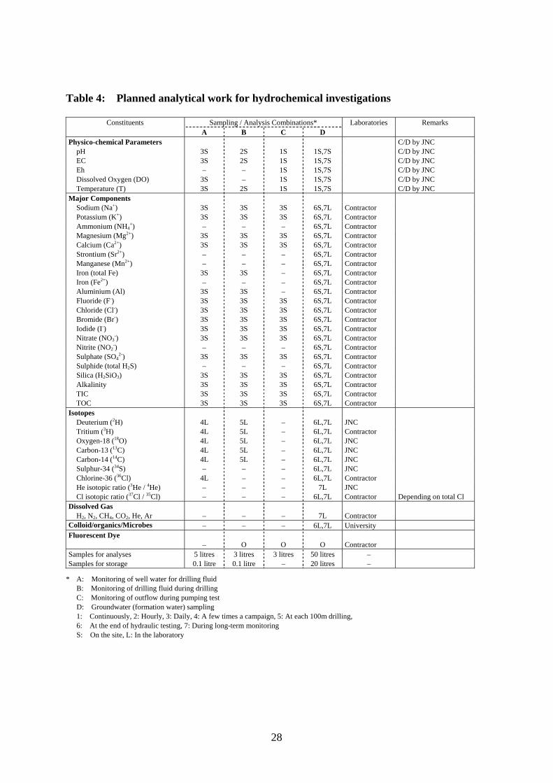
Table 4: Planned analytical work for hydrochemical investigations
Constituents Sampling / Analysis Combinations* Laboratories Remarks A B C D
Physico-chemical Parameters C/D by JNC pH 3S 2S 1S 1S,7S C/D by JNC EC 3S 2S 1S 1S,7S C/D by JNC Eh – – 1S 1S,7S C/D by JNC Dissolved Oxygen (DO) 3S – 1S 1S,7S C/D by JNC Temperature (T) 3S 2S 1S 1S,7S C/D by JNC
Major Components Sodium (Na+) 3S 3S 3S 6S,7L Contractor Potassium (K+) 3S 3S 3S 6S,7L Contractor Ammonium (NH4
+) – – – 6S,7L Contractor Magnesium (Mg2+) 3S 3S 3S 6S,7L Contractor Calcium (Ca2+) 3S 3S 3S 6S,7L Contractor Strontium (Sr2+) – – – 6S,7L Contractor Manganese (Mn2+) – – – 6S,7L Contractor Iron (total Fe) 3S 3S – 6S,7L Contractor Iron (Fe2+) – – – 6S,7L Contractor Aluminium (Al) 3S 3S – 6S,7L Contractor Fluoride (F-) 3S 3S 3S 6S,7L Contractor Chloride (Cl-) 3S 3S 3S 6S,7L Contractor Bromide (Br-) Iodide (I-)
3S 3S
3S 3S
3S 3S
6S,7L 6S,7L
Contractor Contractor
Nitrate (NO3-) 3S 3S 3S 6S,7L Contractor
Nitrite (NO2-) – – – 6S,7L Contractor
Sulphate (SO42-) 3S 3S 3S 6S,7L Contractor
Sulphide (total H2S) – – – 6S,7L Contractor Silica (H2SiO3) 3S 3S 3S 6S,7L Contractor Alkalinity 3S 3S 3S 6S,7L Contractor TIC 3S 3S 3S 6S,7L Contractor TOC 3S 3S 3S 6S,7L Contractor
Isotopes Deuterium (2H) 4L 5L – 6L,7L JNC Tritium (3H) 4L 5L – 6L,7L Contractor Oxygen-18 (18O) 4L 5L – 6L,7L JNC Carbon-13 (13C) 4L 5L – 6L,7L JNC Carbon-14 (14C) 4L 5L – 6L,7L JNC Sulphur-34 (34S) – – – 6L,7L JNC Chlorine-36 (36Cl) 4L – – 6L,7L Contractor He isotopic ratio (3He / 4He) – – – 7L JNC Cl isotopic ratio (37Cl / 35Cl) – – – 6L,7L Contractor Depending on total Cl
Dissolved Gas H2, N2, CH4, CO2, He, Ar – – – 7L Contractor
Colloid/organics/Microbes – – – 6L,7L University Fluorescent Dye – O O O Contractor Samples for analyses 5 litres 3 litres 3 litres 50 litres – Samples for storage 0.1 litre 0.1 litre – 20 litres –
* A: Monitoring of well water for drilling fluid B: Monitoring of drilling fluid during drilling C: Monitoring of outflow during pumping test D: Groundwater (formation water) sampling 1: Continuously, 2: Hourly, 3: Daily, 4: A few times a campaign, 5: At each 100m drilling, 6: At the end of hydraulic testing, 7: During long-term monitoring S: On the site, L: In the laboratory
29
5.6.4 Reporting 5.6.4.1 Reporting by contractor Prompt report during drilling Raw data and the following information on drilling fluid monitoring are reported. • Analysed values with errors and detection limits. • Method used, including details of equipment employed and its operating conditions. • Anything abnormal during monitoring/sampling or analysis. • Any observations of colour changes in water, gas bubbles, precipitation and smell.
Final report (by the end of contract period) All results are compiled and reported with full data sets. The report should include analysed values with errors and detection limits, details of method used, details of equipment employed and its operating conditions and details of anything unexpected that occurred during the monitoring/sampling and analyses. 5.6.4.2 Reporting by JNC The following items are reported by JNC. Hydrochemical modelling and prediction (1) Prediction of hydrochemical condition in the sedimentary rocks around the shallow
boreholes by using the existing qualitative hydrochemical model at the moment. (2) Verification of qualitative hydrochemical model and improvement of the model to
quantitative one to predict the effect of shaft sinking on groundwater geochemistry. Hydraulic condition in the sedimentary rocks at URL area (1) Origin and age determination of groundwater by isotopic approach. (2) Hydrochemical estimation of hydraulic condition and verification of the hydrogeological
model. Redox condition and buffer capacity of the sedimentary rocks (1) In-situ redox profiles and dominant reactions in the sedimentary rocks. (2) Retardation of redox front migration.
30
5.7 LONG-TERM MONITORING The multipacker (MP) system will be installed in each borehole after all the borehole investigations are completed. The data will provide information on the initial states of hydrogeological and hydrochemical environment, and on their changes during/after other borehole investigations and excavation of the underground laboratory. 5.7.1 Aims • To understand and monitor the shallow hydrogeological environment (hydraulic head
and groundwater chemistry) caused by other borehole investigations and shaft excavation.
• To refine procedures for groundwater sampling using the MP system. 5.7.2 Methods In the long-term monitoring programme, hydraulic head and pH-Eh in situ are monitored, and groundwater is sampled, using the multipacker systems. 5.7.3 Planned field work MP system installation (by contractor) The multipacker systems with pressure transducers will be installed into all boreholes while the chemical probes are installed only in the high priority hydrochemical boreholes, MSB-2 and 4. Packer layout for each borehole are designed basically following the hydraulic test sections; representative rock facies of each sedimentary formation (i.e. tuffaceous sandstones and conglomerates), and the weathered granite. Groundwater sampling (by contractor) After installation, water is pumped out and chemical parameters are measured simultaneously until the fluorescent dye concentration decreases to less than 1%. Then the chemical composition and in situ redox parameters are determined as an initial value for long-term monitoring. Some parameters of the drilling fluid and groundwater samples are measured at the site. Comprehensive chemical and isotopic analyses of the water samples are carried out in laboratories by contractor and in house as shown in Table 4. Long-term hydraulic/hydrochemical monitoring (by contractor) Data on hydraulic heads and pH-Eh values are acquired hourly and transferred to the JNC laboratory. Pressure responses are monitored during other hydrogeological investigations in Phase 1 and later during Phase 2, shaft/drift excavations. Information on the spatial distribution and variations in hydraulic heads with time is needed for the evaluation of the groundwater flow system. Hydrochemical information provide constraints on the hydrogeological model and basis for evaluating the geochemical/hydrochemical model and the hypothesis of groundwater mixing.
31
5.7.4 Reporting 5.7.4.1 MP system installation Daily reportⅠ (daily at 8.30) Status of the field work (depth/length of installation, tests performed, anything abnormal or unexpected, etc.) is reported by fax. Daily report Ⅱ(to be supplied to JNC the next morning) Details of installation work, test results and anything abnormal or unexpected are reported, according to the documentation format specified by JNC. Final report (by the end of the contract period) The report should clearly show accurate packed-off intervals, inflation pressure of packers, hydraulic heads and anything abnormal during the installation of the multipacker system. Drawings of the multipacker system and its set-up are appended. 5.7.4.2 Groundwater sampling Prompt report (within 24 hours after sampling) The following information on sampling of the drilling fluids during pumping; details of the system set-up, sampling method, amount of water sampled, concentration of fluorescent dye, temperature, any observation of colour changes in water, gas bubbles, precipitation, smell, major chemical components, redox parameter measurements (pH, Eh, electrical conductivity, DO and temperature) and anything abnormal during the sampling or analyses. Final report (by the end of contract period) All results are compiled and reported with full data sets. The report should include analysed values with errors and detection limits, details of the system set-up, details of sampling and analytical methods employed and their conditions and details of anything unexpected that occurred during the sampling and analyses. 5.7.4.3 Long-term hydraulic/hydrochemical monitoring Weekly report Raw and plotted data of hydraulic head and pH-Eh with time, relevant detection limits and precision, details of the system set-up, measurement method employed, comments on the measurements and details of anything abnormal or unexpected are reported. Final reports (by the end of contract period) All results are compiled and reported with full data sets and relevant information described above. The report should contain the interpretation of the results and comments on the spatial distribution and variations in hydraulic heads with time due to the construction of the underground laboratory.
32
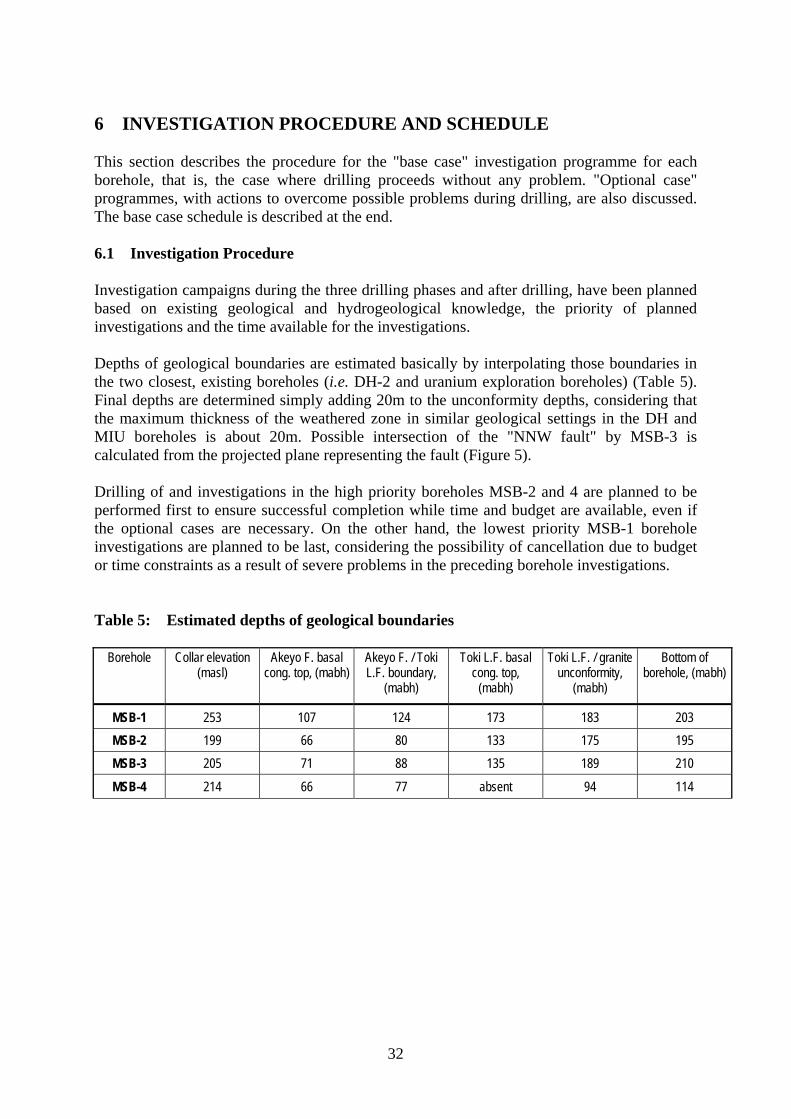
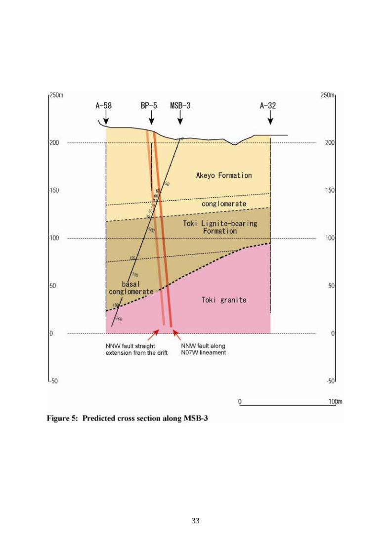
6 INVESTIGATION PROCEDURE AND SCHEDULE This section describes the procedure for the "base case" investigation programme for each borehole, that is, the case where drilling proceeds without any problem. "Optional case" programmes, with actions to overcome possible problems during drilling, are also discussed. The base case schedule is described at the end. 6.1 Investigation Procedure Investigation campaigns during the three drilling phases and after drilling, have been planned based on existing geological and hydrogeological knowledge, the priority of planned investigations and the time available for the investigations. Depths of geological boundaries are estimated basically by interpolating those boundaries in the two closest, existing boreholes (i.e. DH-2 and uranium exploration boreholes) (Table 5). Final depths are determined simply adding 20m to the unconformity depths, considering that the maximum thickness of the weathered zone in similar geological settings in the DH and MIU boreholes is about 20m. Possible intersection of the "NNW fault" by MSB-3 is calculated from the projected plane representing the fault (Figure 5). Drilling of and investigations in the high priority boreholes MSB-2 and 4 are planned to be performed first to ensure successful completion while time and budget are available, even if the optional cases are necessary. On the other hand, the lowest priority MSB-1 borehole investigations are planned to be last, considering the possibility of cancellation due to budget or time constraints as a result of severe problems in the preceding borehole investigations. Table 5: Estimated depths of geological boundaries
Borehole Collar elevation (masl)
Akeyo F. basal cong. top, (mabh)
Akeyo F. / Toki L.F. boundary,
(mabh)
Toki L.F. basal cong. top,
(mabh)
Toki L.F. / granite unconformity,
(mabh)
Bottom of borehole, (mabh)
MSB-1 253 107 124 173 183 203 MSB-2 199 66 80 133 175 195 MSB-3 205 71 88 135 189 210
MSB-4 214 66 77 absent 94 114
33
34
6.1.1 Base case The base case investigation procedures are described below in detail in the order of execution. These are schematically described in Figures 6 to 9. Here all depths are given in depth in metres along borehole (mabh). All PQ wireline drilling uses the triple barrel wireline technique with an acrylic inner barrel. PQ specifications are borehole diameter 123mm and core diameter 78mm. Two types of drilling fluid will be used. Drilling fluid (I) is fresh water tagged with Na-naphtionate used in the Mizuniami Group, and drilling fluid (II) is fresh water tagged with uranine used in the granite. 6.1.1.1 MSB-2 During drilling Phase I 0 - 15 mabh: Surface soil and Akeyo Formation 1. PQ wireline core drilling from surface to 15 mabh with drilling fluid (I). 2. Reaming of borehole to 12 1/4 inches (311 mm). 3. Installation of more than 10 inch dia. (254 mm) casing pipes to 15 mabh and fixing by
full-hole cementing. 4. Installation of 5 inch (127 mm) or PW (127 mm) temporary casing pipes to 15 mabh. 5. Flushing the borehole with drilling fluid (I). Phase II 15 - 155 mabh: Akeyo and Toki Lignite-bearing Formations 6. PQ wireline core drilling with drilling fluid (I) to 155 mabh at the estimated mean point of
basal conglomerate of Toki Lignite-bearing Formation. Recording of drilling parameters such as drilling rate, bit revolution, bit load, torque, pumping pressure, rate of water supply and return in every drilling run. Flushing the borehole to extract cuttings with drilling fluid (I).
7. Removal of PQ wireline tools, PQ rods and 5 inch temporary casing. 8. Single packer hydraulic tests and water sampling at the interval 133 - 155 mabh.
Aims: transmissivity (T), hydraulic head (H) and water sample (W) Lithology: basal conglomerate of the Toki Lignite-bearing Formation
9. Reinstallation of 5 inch temporary casing pipes to 15 mabh. 10. Flushing the borehole with drilling fluid (II) until the concentration of previous drilling
fluid (I) is decreased to less than 1 %. Phase III 155 - max.195 mabh: Toki Lignite-bearing Formation and weathered Toki granite 11. PQ wireline core drilling with drilling fluid (II) to 5 m below the bottom of weathered
granite, maximum 195 mabh. Flushing the borehole to extract cuttings with drilling fluid (II) after drilling.
12. Removal of PQ wireline tools, PQ rods and 5 inch temporary casing. After drilling 13. Single packer hydraulic tests and water sampling from the unconformity at 175 mabh to
35
the bottom of borehole, or optionally to the bottom of weathered granite using double packers.
Aims: T, H, W Lithology: weathered Toki granite
14. Borehole TV, geophysical and fluid logging from 15 mabh to the bottom of borehole. 15. Double packer hydraulic tests on the main part of Toki Lignite-bearing Formation from 80
to 133 mabh, basal conglomerate of Akeyo Formation from 66 to 80 mabh, and main part of Akeyo Formation from 15 to 66 mabh.
Aims: T, H Lithology: Toki Lignite-bearing and Akeyo Formations
16. Flushing the borehole with drilling fluid (II). 6.1.1.2 MSB-4 During drilling Phase I 0 - 10 mabh: Surface soil and Akeyo Formation 1. PQ wireline core drilling from surface to 10mabh with drilling fluid (I). 2. Reaming of borehole to 12 1/4 inches (311 mm). 3. Installation of more than 10 inch dia. (254 mm) casing pipes to 10mabh and fixing by
full-hole cementing. 4. Installation of 5 inch (127 mm) or PW (127 mm) temporary casing pipes to 10 mabh. 5. Flushing the borehole with drilling water (I) after dredging cement. Phase II 10 - 91 mabh: Akeyo and Toki Lignite-bearing Formations 6. PQ wireline core drilling with drilling fluid (I) to 91 mabh at the estimated mean point of
gamma ray anomaly zone where the basal conglomerate is absent above the unconformity. Recording of drilling parameters such as drilling rate, bit revolution, bit load, torque, pumping pressure, rate of water supply and return in every drilling run. Flushing the borehole to extract cuttings with drilling fluid (I).
7. Removal of PQ wireline tools, PQ rods and 5 inch temporary casing. 8. Single packer hydraulic tests and water sampling at the interval 77 - 91 mabh.
Aims: transmissivity (T), hydraulic head (H) and water sample (W) Lithology: main part of the Toki Lignite-bearing Formation
9. Reinstallation of 5 inch temporary casing pipes to 10 mabh. 10. Flushing the borehole with drilling fluid (II) until the concentration of previous drilling
fluid (I) is reduced to less than 1 %. Phase III 91 - max.114 mabh: Toki Lignite-bearing Formation and weathered Toki granite 11. PQ wireline core drilling with drilling fluid (II) to 5 m below the bottom of weathered
granite, maximum 114 mabh. Flushing the borehole to extract cuttings with drilling fluid (II) after drilling.
12. Removal of PQ wireline tools, PQ rods and 5 inch temporary casing.
36
After drilling 13. Single packer hydraulic tests and water sampling from the unconformity at 94 mabh to the
bottom of borehole, or optionally to the bottom of weathered granite using double packers. Aims: T, H, W Lithology: weathered Toki granite
14. Borehole TV, geophysical and fluid logging from 10 mabh to the bottom of borehole. 15. Double packer hydraulic tests on the basal conglomerate of Akeyo Formation from 66 to
77 mabh, and main part of Akeyo Formation from 10 to 66 mabh. Aims: T, H Lithology: Akeyo Formation
16. Flushing the borehole with drilling fluid (II). 6.1.1.3 MSB-3 During drilling Phase I 0 - 10 mabh: Surface soil and Akeyo Formation 1. Drilling using either a tricone bit or an air hammer with drilling fluid (I) from surface to
10 mabh. Borehole diameter is 12 1/4 inches (311 mm). 2. Installation of more than 10 inch (254 mm) casing pipes to 10 mabh and fixing by
full-hole cementing. 3. Installation of 5 inch (127 mm) or PW (127 mm) temporary casing pipes to 10 mabh. 4. Flushing the borehole with drilling water (I) after dredging cement. Phase II 10 - 189 mabh: Akeyo and Toki Lignite-bearing Formations 5. PQ wireline core drilling with drilling fluid (I) to 189mabh immediately below the
unconformity between Toki Lignite-bearing Formation and granite. Recording of drilling parameters such as drilling rate, bit revolution, bit load, torque, pumping pressure, rate of water supply and return in every drilling run. Intersection of the "NNW fault" (strike N07W based on the lineament, dip 85E and apparent thickness 6 m based on the tunnel exposures) is predicted to occur from 60 to 66 mabh in the main part of Akeyo Formation. No hydraulic testing is planned in this phase unless a problem occurs. The intersection depth is estimated to be from 77 to 83 mabh in the Akeyo formation conglomerate, if a straight extension of the "NNW fault" from the drift is assumed.
6. Flushing the borehole with drilling water (II) until the concentration of previous drilling fluid (I) is reduced to less than 1 %.
Phase III 189 - max.210 mabh: Weathered Toki granite 7. PQ wireline core drilling with drilling water (II) to 5 m below the bottom of weathered
granite, maximum 210 mabh. Flushing the borehole to extract cuttings with drilling fluid (II) after drilling.
8. Removal of PQ wireline tools, PQ rods and 5 inch temporary casing.
37
After drilling 9. Borehole TV, geophysical and fluid logging from 10 mabh to the bottom of borehole. 10. Single packer hydraulic tests and water sampling from the unconformity at 189 mabh to
the bottom of borehole, or optionally to the bottom of weathered granite using double packers.
Aims: T, H Lithology: weathered Toki granite
11. Double packer hydraulic tests on the "NNW fault" from 60 to 66 mabh. Aims: T, H Lithology: fault (highly fractured zone)
12. Flushing the borehole with drilling fluid (II). 6.1.1.4 MSB-1 During drilling Phase I 0 - 15 mabh: Surface soil and Akeyo Formation 1. PQ wireline core drilling from surface to 15 mabh with drilling fluid (I). 2. Reaming of borehole to 12 1/4 inches (311 mm). 3. Installation of more than 10 inch dia. (254 mm) casing pipes to 15mabh and fixing by
full-hole cementing. 4. Installation of 5 inch (127 mm) or PW (127 mm) temporary casing pipes to 15mabh. 5. Flushing the borehole with drilling fluid (I) after dredging cement. Phase II 15 - 183 mabh: Akeyo and Toki Lignite-bearing Formations 6. PQ wireline core drilling with drilling fluid (I) to 183 mabh immediately below the
unconformity between Toki Lignite-bearing Formation and granite. Recording of drilling parameters such as drilling rate, bit revolution, bit load, torque, pumping pressure, rate of water supply and return in every drilling run.
7. Flushing the borehole with drilling fluid (II) until the concentration of previous drilling fluid (I) is reduced to less than 1 %.
Phase III 183 - max.203 mabh: Weathered Toki granite 8. PQ wireline core drilling with drilling fluid (II) to 5 m below the bottom of weathered
granite, maximum 203 mabh. Flushing the borehole to extract cuttings with drilling fluid (II) after drilling.
9. Removal of PQ wireline tools, PQ rods and 5inch temporary casing. After drilling 10. Borehole TV, geophysical and fluid logging from 15 mabh to the bottom of borehole. 11. Single packer hydraulic tests and water sampling from the unconformity at 183 mabh to
the bottom of borehole, or optionally to the bottom of weathered granite using double packers.

38
Aims: T, H Lithology: weathered Toki granite
12. Flushing the borehole with drilling fluid (II).
39
40
41
42
43
6.1.2 Optional cases Possible problems during drilling and alternative programs for solution are described in Table 6. Basic idea is that establishment of four stable boreholes in the planned locations and depths for the MP installation has the highest priority. Common procedures for all boreholes are summarised below. • In case of a significant loss of drilling fluid (more than 50 %) that makes continued
drilling impossible, the feature is immediately tested to estimate its hydraulic properties, then sealed with LCM (lost circulation material) instead of cementing to avoid chemical contamination of groundwater.
• In case of a significant collapse that makes continued drilling impossible, all the planned investigations above the problem depth are performed, then the borehole is reinforced with casing and full-hole cementing. Upon installation of a MP system, the borehole is perforated by conventional explosive method.
• In case of coincidental, significant fluid loss and borehole collapse, the procedure for borehole collapse is implemented.
• If a significant enlargement of borehole diameter (more than 140mm) occurs at the candidate packer locations for hydraulic tests, drilling is stopped and tests are immediately performed.
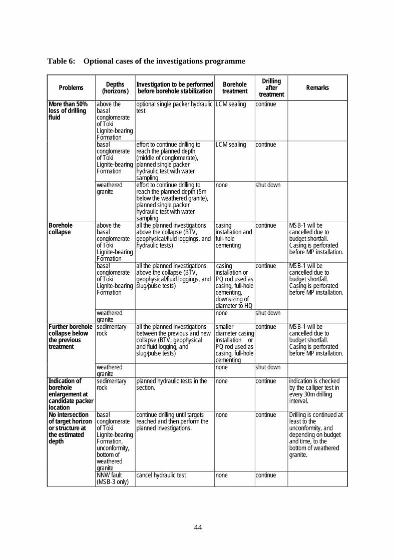
44
Table 6: Optional cases of the investigations programme
Problems Depths (horizons)
Investigation to be performed before borehole stabilization
Borehole treatment
Drilling after
treatment Remarks
above the basal conglomerate of Toki Lignite-bearing Formation
optional single packer hydraulic test
LCM sealing continue
basal conglomerate of Toki Lignite-bearing Formation
effort to continue drilling to reach the planned depth (middle of conglomerate), planned single packer hydraulic test with water sampling
LCM sealing continue
More than 50% loss of drilling fluid
weathered granite
effort to continue drilling to reach the planned depth (5m below the weathered granite), planned single packer hydraulic test with water sampling
none shut down
above the basal conglomerate of Toki Lignite-bearing Formation
all the planned investigations above the collapse (BTV, geophysical/fluid loggings, and hydraulic tests)
casing installation and full-hole cementing
continue MSB-1 will be cancelled due to budget shortfall. Casing is perforated before MP installation.
basal conglomerate of Toki Lignite-bearing Formation
all the planned investigations above the collapse (BTV, geophysical/fluid loggings, and slug/pulse tests)
casing installation or PQ rod used as casing, full-hole cementing, downsizing of diameter to HQ
continue MSB-1 will be cancelled due to budget shortfall. Casing is perforated before MP installation.
Borehole collapse
weathered granite
none shut down
sedimentary rock
all the planned investigations between the previous and new collapse (BTV, geophysical and fluid logging, and slug/pulse tests)
smaller diameter casing installation or PQ rod used as casing, full-hole cementing
continue MSB-1 will be cancelled due to budget shortfall. Casing is perforated before MP installation.
Further borehole collapse below the previous treatment
weathered granite
none shut down
Indication of borehole enlargement at candidate packer location
sedimentary rock
planned hydraulic tests in the section.
none continue indication is checked by the calliper test in every 30m drilling interval.
basal conglomerate of Toki Lignite-bearing Formation, unconformity, bottom of weathered granite
continue drilling until targets reached and then perform the planned investigations.
none continue Drilling is continued at least to the unconformity, and depending on budget and time, to the bottom of weathered granite.
No intersection of target horizon or structure at the estimated depth
NNW fault (MSB-3 only)
cancel hydraulic test none continue
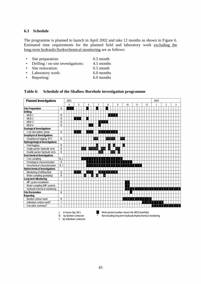
45
6.3 Schedule The programme is planned to launch in April 2002 and take 12 months as shown in Figure 6. Estimated time requirements for the planned field and laboratory work excluding the long-term hydraulic/hydrochemical monitoring are as follows: • Site preparation: 0.5 month • Drilling / on-site investigations: 4.5 months • Site restoration: 0.5 month • Laboratory work: 6.0 months • Reporting: 6.0 months
Table 6: Schedule of the Shallow Borehole investigation programme
Planned Investigations 2002 2003 4 5 6 7 8 9 10 11 12 1 2 3 Site Preparation B
Drilling
MSB-1 B
MSB-2 B
MSB-3 B
MSB-4 B
Geological Investigations
Core description, photo B
Geophysical Investigations
Geophysical logging, BTV B 2 2 4 4 3 3 1 1
Hydrogeological Investigations
Fluid logging B 2 4 3 1
Single packer hydraulic tests B 2 2 2 2 4 4 4 4 3 3 1
Double packer hydraulic tests B 2 2 4 4 3
Geochemical Investigations
Core sampling B, J
Petrological characterisation B
Geochemical characterisation B, I
Hydrochemical Investigations
Monitoring of drilling fluid B
Water sampling (pumping) B 2 2 4 4
Long-term Monitoring
MP system installation I
Water sampling (MP system) I
Hydraulic/chemical monitoring I
Site Restoration B
Reporting
blanket contract work B
individual contract work* I
Executive summary* J
J: in house (by JNC) Work period (number means the MSB borehole) B: by blanket contractor * Not including long-term hydraulic/hydrochemical monitoring I: by individual contractor

46
7 QUALITY ASSURANCE/CONTROL AND REPORTING It is required that a quality assurance (QA) system be applied to all activities and operations carried out by contractors, which meets at least national standards. In addition, JNC has responsibility for quality control (QC) of each aspect throughout the contract work and for careful review of their deliverables as described in the preceding sections. JNC’s QC system is employed to ensure that the purpose for which the work is carried out is likely to be successfully achieved. It is also intended, for QC purposes, to have external review by experts (e.g. under international collaboration studies) in the particular field during the Shallow Borehole Investigation programme. The final report of the Shallow Borehole Investigation is produced by JNC in the form of an executive summary a few months after all the relevant reports are submitted. All field and laboratory data are compiled and achievements corresponding to the aims stated in Section 3 are evaluated, which should be brought into a broader context in the executive summary. The report also discusses contributions to the next or near-future programmes (e.g. planning of the 2nd stage investigations and design/construction of the connecting drifts).
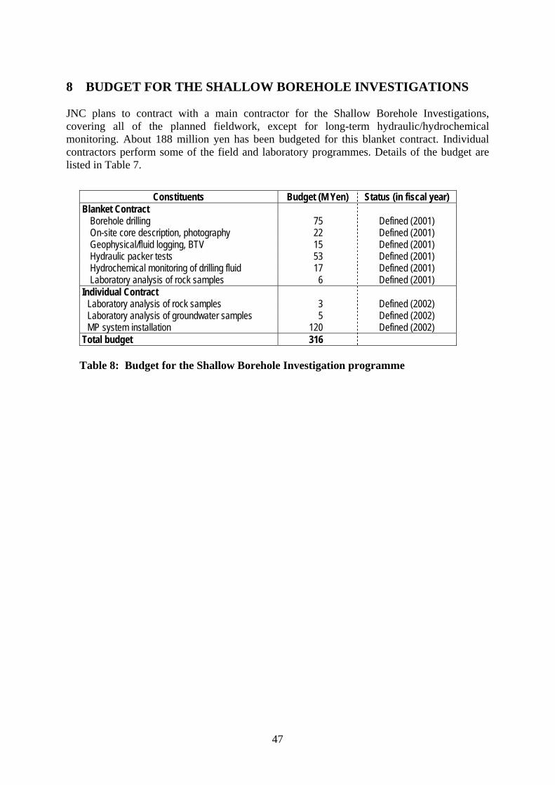
47
8 BUDGET FOR THE SHALLOW BOREHOLE INVESTIGATIONS JNC plans to contract with a main contractor for the Shallow Borehole Investigations, covering all of the planned fieldwork, except for long-term hydraulic/hydrochemical monitoring. About 188 million yen has been budgeted for this blanket contract. Individual contractors perform some of the field and laboratory programmes. Details of the budget are listed in Table 7.
Constituents Budget (M Yen) Status (in fiscal year) Blanket Contract
Borehole drilling 75 Defined (2001) On-site core description, photography 22 Defined (2001) Geophysical/fluid logging, BTV 15 Defined (2001) Hydraulic packer tests 53 Defined (2001) Hydrochemical monitoring of drilling fluid 17 Defined (2001) Laboratory analysis of rock samples 6 Defined (2001)
Individual Contract Laboratory analysis of rock samples 3 Defined (2002) Laboratory analysis of groundwater samples 5 Defined (2002) MP system installation 120 Defined (2002)
Total budget 316
Table 8: Budget for the Shallow Borehole Investigation programme

48
REFERENCE Japan Nuclear Cycle Development Cooperation, 2002: General plan of the Mizunami Underground Research Laboratory. JNC Technical Report (in Japanese), (in preparation), JNC Tono Geoscience Centre, Toki, Japan.
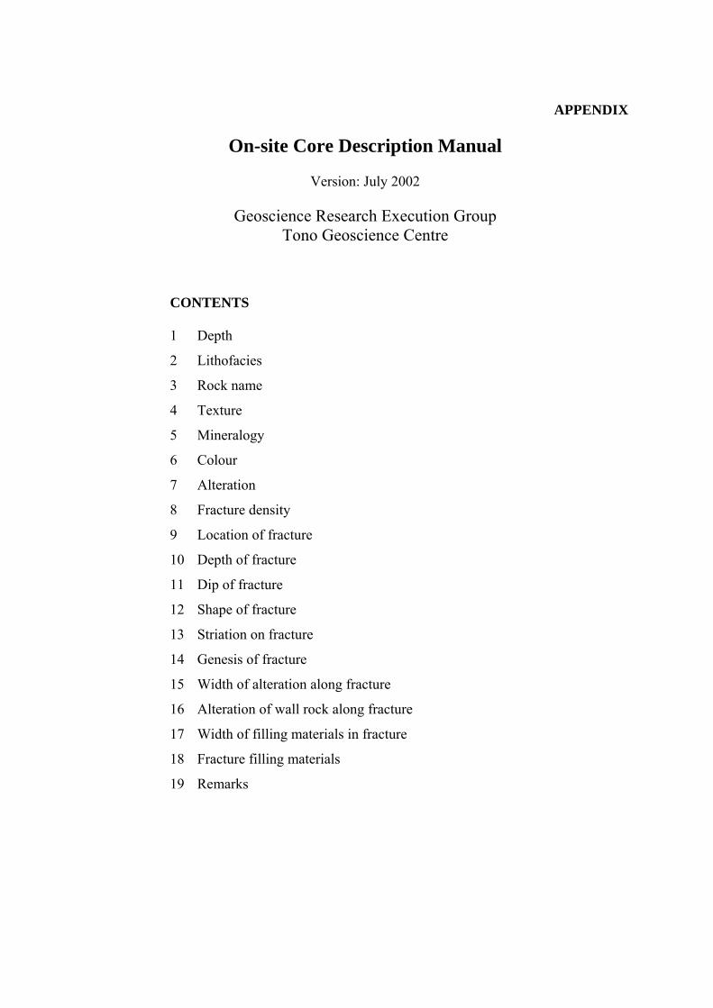
APPENDIX
On-site Core Description Manual
Version: July 2002
Geoscience Research Execution Group Tono Geoscience Centre
CONTENTS 1 Depth
2 Lithofacies
3 Rock name
4 Texture
5 Mineralogy
6 Colour
7 Alteration
8 Fracture density
9 Location of fracture
10 Depth of fracture
11 Dip of fracture
12 Shape of fracture
13 Striation on fracture
14 Genesis of fracture
15 Width of alteration along fracture
16 Alteration of wall rock along fracture
17 Width of filling materials in fracture
18 Fracture filling materials
19 Remarks
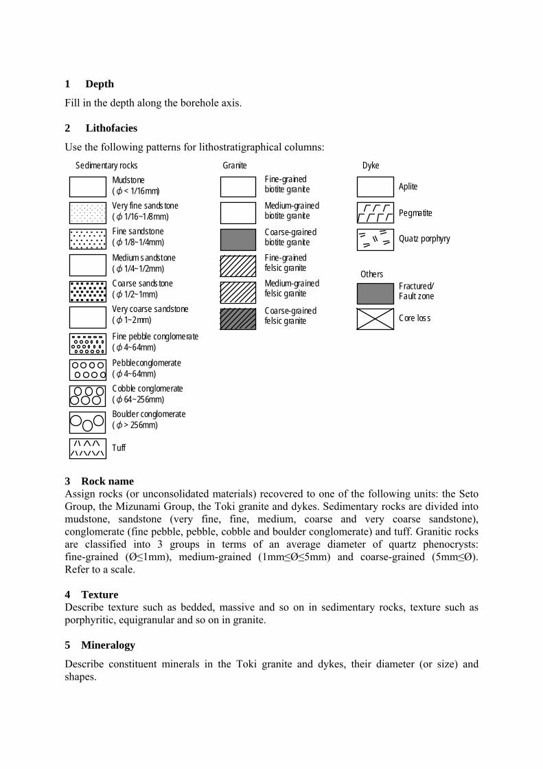
1 Depth
Fill in the depth along the borehole axis. 2 Lithofacies
Use the following patterns for lithostratigraphical columns:
3 Rock name Assign rocks (or unconsolidated materials) recovered to one of the following units: the Seto Group, the Mizunami Group, the Toki granite and dykes. Sedimentary rocks are divided into mudstone, sandstone (very fine, fine, medium, coarse and very coarse sandstone), conglomerate (fine pebble, pebble, cobble and boulder conglomerate) and tuff. Granitic rocks are classified into 3 groups in terms of an average diameter of quartz phenocrysts: fine-grained (Ø≤1mm), medium-grained (1mm≤Ø≤5mm) and coarse-grained (5mm≤Ø). Refer to a scale. 4 Texture Describe texture such as bedded, massive and so on in sedimentary rocks, texture such as porphyritic, equigranular and so on in granite. 5 Mineralogy
Describe constituent minerals in the Toki granite and dykes, their diameter (or size) and shapes.
Fine sandstone (φ1/8~1/4mm)
Mudstone (φ< 1/16mm)
Tuff
Aplite
Pegmatite
Fine-grained biotite granite
Medium-grained biotite granite
Coarse-grained biotite granite Quatz porphyry
Fractured/ Fault zone
Core loss
Sedimentary rocks Granite Dyke
Others
Fine-grained felsic graniteMedium-grained felsic granite
Coarse-grained felsic granite
Cobble conglomerate (φ64~256mm)
Medium sandstone (φ1/4~1/2mm)Coarse sandstone (φ1/2~1mm)
Pebbleconglomerate (φ4~64mm)
Boulder conglomerate (φ> 256mm)
Very fine sandstone (φ1/16~1/8mm)
Very coarse sandstone (φ1~2mm)
・・・・・・・
・・・・・・・・・・・・・・・・・・・・・・・・・・・・
・・・・・・・
・・・・・・・ ・・・・・・・・・・・・・・ ・・・・・・・
・ ・ ・ ・・・・
・ ・ ・ ・・・・・ ・ ・ ・・・・ ・ ・ ・ ・・・・・ ・ ・ ・・・・
・ ・ ・ ・・・・・ ・ ・ ・・・・
Fine pebble conglomerate (φ4~64mm)
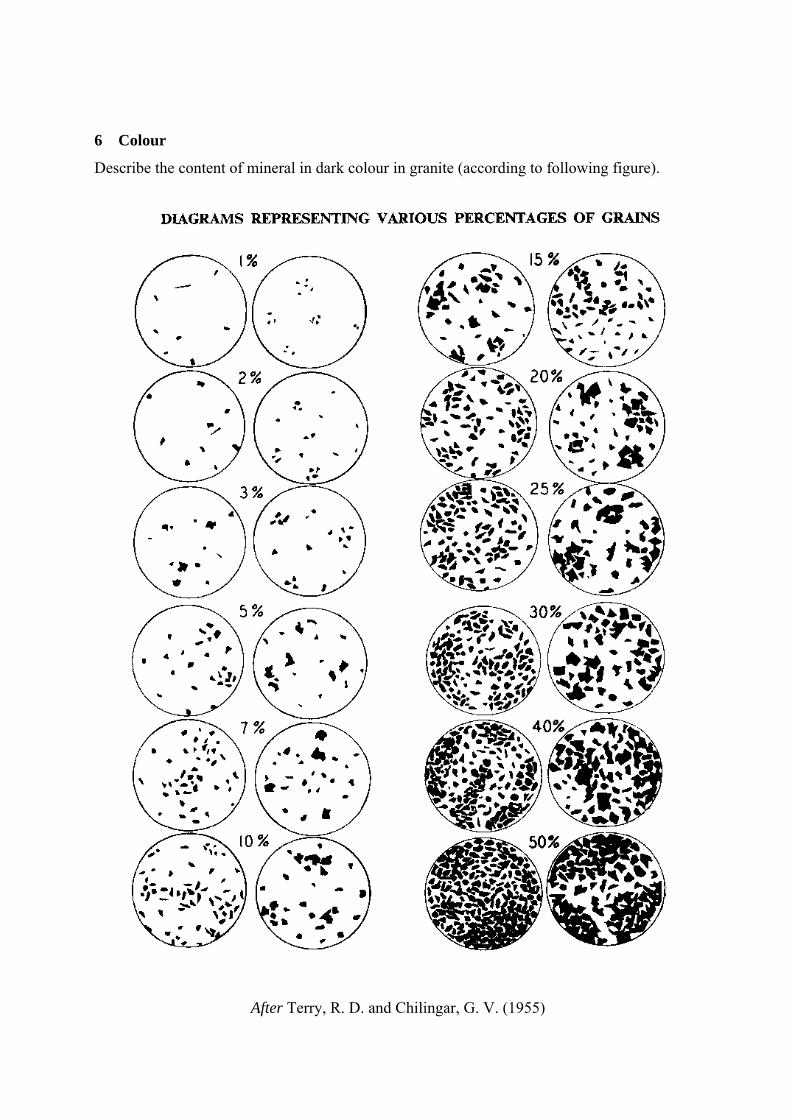
6 Colour
Describe the content of mineral in dark colour in granite (according to following figure).
T e r r y , R . D . a nd C hilingar,G .V .(1955)より引用After Terry, R. D. and Chilingar, G. V. (1955)

7 Alteration
Define the degree of alteration according to the following definitions: Class Definition
1 (fresh) Unaffected by alteration. 2 (weak) Rock fabric completely preserved. Stained/bleached to some extent. Unaltered volume over 50%. 3 (moderate) Original rock texture recognisable. Some unaltered volume. 4 (strong) Minerals and fragments altered to clay minerals. Original rock texture no longer recognisable.
Define the distribution of alteration according to the following definitions: Class Definition
P Homogeneous altered in pervasive area. I Irregular altered in partly area. S Altered Spotty. N Altered in network. D Dissolved mineral recognisable.
8 Fracture density
Fill in the number of fractures per 1m core.
9 Location of fracture
Fill in the upper and lower depths of fracture on both sides of the column. Measure apparent dip to the core axis.
10 Depth of fracture
Describe the depth intersection between fracture and core axis.
11 Dip of fracture
Describe the angle of fracture with core axis.
12 Shape of fracture
Classify shape of fractures according to the following definitions: Type Definition
Sr (stepped rough) Stepped shaped with rough fracture plane. Sf (stepped flat) Stepped shaped with flat fracture plane. Ss(stepped slickenside) Stepped shaped. Striation on a slickensided surface. Wr (wavy rough) Wavy shaped with rough fracture plane. Wf (wavy flat) Wavy shaped with flat fracture plane. Ws (wavy slickenside) Wavy shaped. Striation on a slickensided surface. Pr (planar rough) Planar shaped with rough fracture plane. Pf (planar flat) Planar shaped with flat fracture plane. Ps (planarslickenside) Planar shaped. Striation on a slickensided surface.
13 Striation on fracture
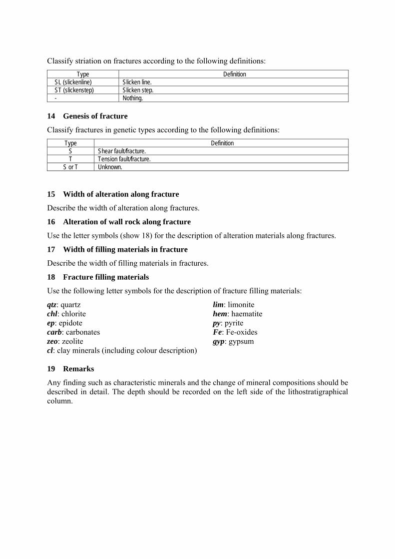
Classify striation on fractures according to the following definitions: Type Definition
SL (slickenline) Slicken line. ST (slickenstep) Slicken step. - Nothing.
14 Genesis of fracture
Classify fractures in genetic types according to the following definitions: Type Definition
S Shear fault/fracture. T Tension fault/fracture.
S or T Unknown. 15 Width of alteration along fracture
Describe the width of alteration along fractures.
16 Alteration of wall rock along fracture
Use the letter symbols (show 18) for the description of alteration materials along fractures.
17 Width of filling materials in fracture
Describe the width of filling materials in fractures.
18 Fracture filling materials
Use the following letter symbols for the description of fracture filling materials:
qtz: quartz lim: limonite chl: chlorite hem: haematite ep: epidote py: pyrite carb: carbonates Fe: Fe-oxides zeo: zeolite gyp: gypsum cl: clay minerals (including colour description) 19 Remarks
Any finding such as characteristic minerals and the change of mineral compositions should be described in detail. The depth should be recorded on the left side of the lithostratigraphical column.