Embed Size (px)
Citation preview
Source: Documents 8B/37, 8B/49 Att. 10, 8B/79, 8B/100 Att. 12, 8B/TEMP/58
Working Party 8B
PRELIMINARY DRAFT NEW RECOMMENDATION ITU-R M.[DOC. 8B/37, 8B/49 ATT. 10, 8B/100 ATT. 12]
Characteristics of and protection criteria for radiolocation, aeronautical radionavigation and meteorological radars
operating in the frequency bands between 5 250 and 5 850 MHz
(Question ITU-R 226/8)
This PDNR originated as Document 8B/37 and revisions were attached to the Chairman's reports of meetings of WP 8B (Documents 8B/49 Att. 10, 8B/100 Att. 12). Document 8B/79 was submitted to the May 2001 meeting but carried forward to the October 2001 meeting and contains information about weather radar systems operating in the United Kingdom. This meeting noted also information concerning meteorological radars operating in Canada, in Document 8B/TEMP/58.
This information was taken into account in revising the PDNR. The system in the United Kingdom is coordinated with systems in other European countries, therefore the overall characteristics of the coordinated networks have been included.
The full text of the PDNR as amended is given in the Annex hereto.
/TT/FILE_CONVERT/5AD27FE87F8B9A05208CC49D/DOCUMENT.DOC (134032) 07.05.23 07.05.23
INTERNATIONAL TELECOMMUNICATION UNION AMCP WF7/WP19
RADIOCOMMUNICATIONSTUDY GROUPS
Document 8B/TEMP/63-E29 October 2001English only
- 2 -8B/TEMP/63-E
ANNEX 1
Revision to Document 8B/100 (Attachment 12)
PRELIMINARY DRAFT NEW RECOMMENDATION ITU-R M.[DOC. 8B/37]
Characteristics of and protection criteria for radiolocation, aeronautical radionavigation and meteorological radars
operating in the frequency bands between 5 250 and 5 850 MHz
(Question ITU-R 226/8)
The attached preliminary draft new Recommendation (PDNR) presents the technical characteristics and protection criteria of meteorological, radiolocation and aeronautical radionavigation radars operating in the bands between 5 250-5 850 MHz. This information can be used for conduction sharing studies between incumbent systems operating between 5 250 and 5 850 MHz and new services.
Attachment: 1
/TT/FILE_CONVERT/5AD27FE87F8B9A05208CC49D/DOCUMENT.DOC (134032) 07.05.23 07.05.23
- 3 -8B/TEMP/63-E
ATTACHMENT 1
(to Annex 1)
PRELIMINARY DRAFT NEW RECOMMENDATION ITU-R M.[8B-CHAR]
Characteristics of and protection criteria for radiolocation, aeronautical radionavigation and meteorological radars
operating in the frequency bands between 5 250 and 5 850 MHz
Summary
This Recommendation describes the technical and operational characteristics of, and protection criteria for, radars operating in the frequency band 5 250-5 850 MHz. These characteristics are intended for use when assessing the compatibility of these systems with other services.
The ITU Radiocommunication Assembly,
considering
a) that antenna, signal propagation, target detection, and large necessary bandwidth characteristics of radar to achieve their functions are optimum in certain frequency bands;
b) that the technical characteristics of radiolocation, radionavigation and meteorological radars are determined by the mission of the system and vary widely even within a band;
c) that the radionavigation service is a safety service as specified by RR No. S4.10 and harmful interference to it cannot be accepted;
d) that considerable radiolocation and radionavigation spectrum allocations (amounting to about 1 GHz) have been removed or downgraded since WARC-79;
e) that some ITU-R technical groups are considering the potential for the introduction of new types of systems (e.g. fixed wireless access and high density fixed and mobile systems) or services in bands between 420 MHz and 34 GHz used by radionavigation, radiolocation and meteorological radars;
f) that representative technical and operational characteristics of radiolocation, radionavigation and meteorological radars are required to determine the feasibility of introducing new types of systems into frequency bands in which the latter are operated;
g) that procedures and methodologies to analyse compatibility between radars and systems in other services are provided in ITU-R M.1461;
h) that radiolocation, radionavigation and meteorological radars operate in the bands between 5 250-5 850 MHz;
j) that ground-based radars used for meteorological purposes are authorized to operate in the band 5 600-5 650 MHz on a basis of equality with stations in the aeronautical radionavigation service (see RR No. S5.452),
/TT/FILE_CONVERT/5AD27FE87F8B9A05208CC49D/DOCUMENT.DOC (134032) 07.05.23 07.05.23
- 4 -8B/TEMP/63-E
recommends
1 that the technical and operational characteristics of the radiolocation, radionavigation and meteorological radars described in Annex 1 be considered representative of those operating in the frequency bands between 5 250 and 5 850 MHz (see NOTE);
2 that Recommendation ITU-R M.1461 be used as a guideline in analysing compatibility between radiolocation, radionavigation and meteorological radars with systems in other services; that the criterion of interfering signal power to radar receiver noise power level (I/N) of –6 dB be used as the required protection level for the radiolocation [and meteorological radars], and that the criterion (I/N) of [–10 dB] be used as the required protection level for safety-of-life (per S4.10) radionavigation radars [and meteorological radars]. These protection criteria represent the net protection level if multiple interferers are present.
NOTE - Recommendation ITU-R M.1313 should be used with regard to the characteristics of maritime radionavigation radars in the frequency band 5 470-5 650 MHz.
ANNEX 1
(to PDNR M.[8B-Char])
Characteristics of radiolocation, aeronautical radionavigation
and meteorological radars
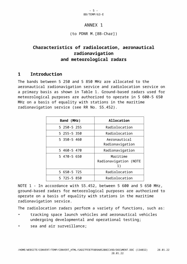
1 IntroductionThe bands between 5 250 and 5 850 MHz are allocated to the aeronautical radionavigation service and radiolocation service on a primary basis as shown in Table 1. Ground-based radars used for meteorological purposes are authorized to operate in 5 600-5 650 MHz on a basis of equality with stations in the maritime radionavigation service (see RR No. S5.452).
Band (MHz) Allocation
5 250-5 255 Radiolocation5 255-5 350 Radiolocation5 350-5 460 Aeronautical Radionavigation5 460-5 470 Radionavigation5 470-5 650 Maritime Radionavigation
(NOTE 1)5 650-5 725 Radiolocation5 725-5 850 Radiolocation
/TT/FILE_CONVERT/5AD27FE87F8B9A05208CC49D/DOCUMENT.DOC (134032) 07.05.23 07.05.23
- 5 -8B/TEMP/63-E
NOTE 1 - In accordance with S5.452, between 5 600 and 5 650 MHz, ground-based radars for meteorological purposes are authorized to operate on a basis of equality with stations in the maritime radionavigation service.
The radiolocation radars perform a variety of functions, such as:• tracking space launch vehicles and aeronautical vehicles undergoing developmental and
operational testing; • sea and air surveillance;
/TT/FILE_CONVERT/5AD27FE87F8B9A05208CC49D/DOCUMENT.DOC (134032) 07.05.23 07.05.23
- 6 -8B/TEMP/63-E
• environmental measurements (e.g. study of ocean water cycles and weather phenomena such as hurricanes);
• Earth imaging; and• national defence and multinational peacekeeping.
The aeronautical radionavigation radars are used primarily for airborne weather avoidance and windshear detection, and perform a safety service (see RR No. S4.10).
The meteorological radars are used for detection of severe weather elements such as tornadoes, hurricanes and violent thunderstorms. These weather radars also provide quantitative area precipitation measurements so important in hydrologic forecasting of potential flooding. This information is used to provide warnings to the public and it therefore provides a safety-of-life service.
Recommendation ITU-R M.1313 should be used with regard to the characteristics of maritime radionavigation radars in the frequency band 5 470-5 650 MHz.
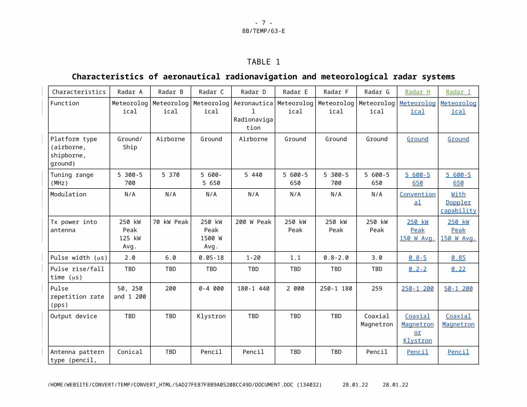
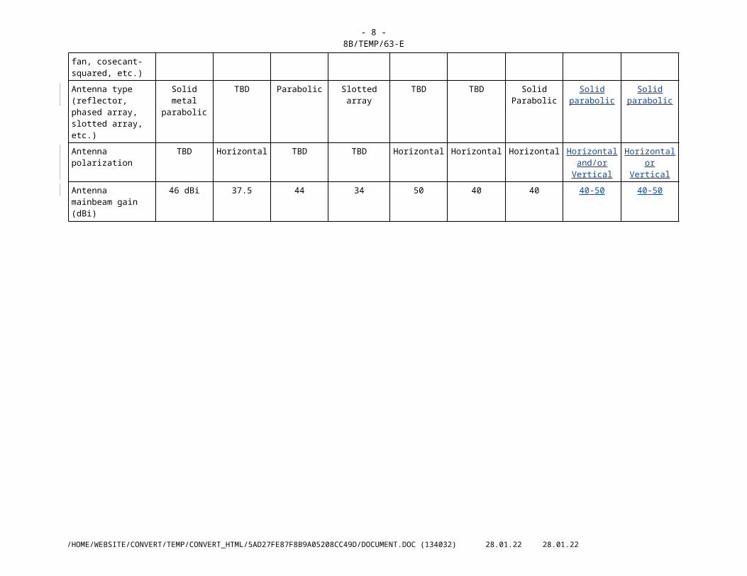
2 Technical characteristics The bands between 5 250 and 5 850 MHz are used by many different types of radars on land-based fixed, shipborne, airborne, and transportable platforms. Tables 1 and 2 contain technical characteristics of representative systems deployed in these bands. This information is sufficient for general calculation to assess the compatibility between these radars and other systems.
/TT/FILE_CONVERT/5AD27FE87F8B9A05208CC49D/DOCUMENT.DOC (134032) 07.05.23 07.05.23
- 7 -8B/TEMP/63-E
TABLE 1
Characteristics of aeronautical radionavigation and meteorological radar systemsCharacteristics Radar A Radar B Radar C Radar D Radar E Radar F Radar G Radar H Radar I
Function Meteorological Meteorological Meteorological Aeronautical Radionavigation
Meteorological Meteorological Meteorological Meteorological Meteorological
Platform type (airborne, shipborne, ground)
Ground/Ship Airborne Ground Airborne Ground Ground Ground Ground Ground
Tuning range (MHz) 5 300-5 700 5 370 5 600-5 650 5 440 5 600-5 650 5 300-5 700 5 600-5 650 5 600-5 650 5 600-5 650
Modulation N/A N/A N/A N/A N/A N/A N/A Conventional With Doppler capability
Tx power into antenna 250 kW Peak125 kW Avg.
70 kW Peak 250 kW Peak1500 W Avg.
200 W Peak 250 kW Peak 250 kW Peak 250 kW Peak 250 kW Peak150 W Avg.
250 kW Peak150 W Avg.
Pulse width (s) 2.0 6.0 0.05-18 1-20 1.1 0.8-2.0 3.0 0.8-5 0.85
Pulse rise/fall time (s) TBD TBD TBD TBD TBD TBD TBD 0.2-2 0.22
Pulse repetition rate (pps)
50, 250 and 1 200
200 0-4 000 180-1 440 2 000 250-1 180 259 250-1 200 50-1 200
Output device TBD TBD Klystron TBD TBD TBD Coaxial Magnetron
Coaxial Magnetron or
Klystron
Coaxial Magnetron
Antenna pattern type (pencil, fan, cosecant-squared, etc.)
Conical TBD Pencil Pencil TBD TBD Pencil Pencil Pencil
Antenna type (reflector, phased array, slotted array, etc.)
Solid metal parabolic
TBD Parabolic Slotted array TBD TBD Solid Parabolic Solid parabolic Solid parabolic
Antenna polarization TBD Horizontal TBD TBD Horizontal Horizontal Horizontal Horizontal and/or Vertical
Horizontal or Vertical
Antenna mainbeam gain (dBi)
46 dBi 37.5 44 34 50 40 40 40-50 40-50
/TT/FILE_CONVERT/5AD27FE87F8B9A05208CC49D/DOCUMENT.DOC (134032) 07.05.23 07.05.23
- 8 -8B/TEMP/63-E
TABLE 1 (CONTINUED)
Characteristics Radar A Radar B Radar C Radar D Radar E Radar F Radar G Radar H Radar I
Antenna elevation beamwidth (degrees)
4.8 4.1 0.95 3.5 <0.55 <1.0 1.65 0.5-2 0.5-2
Antenna azimuthal beamwidth (degrees)
0.65 1.1 0.95 3.5 <.55 <1.0 1.65 0.5-2 0.5-2
Antenna horizontal scan rate (degrees/s)
0.65 TBD 0-36(0-6 rpm)
20 TBD TBD TBD 618(1-3 rpm)
618(1-3 rpm)
Antenna horizontal scan type (continuous, random, 360, sector, etc.)
360 TBD 360 Continuous TBD TBD 360 360 360
Antenna vertical scan rate (degrees/s)
Not applicable TBD N/A 45 TBD TBD TBD 1-10 1-14
Antenna vertical scan type (continuous, random, 360, sector, etc.) (degrees)
Not applicable TBD N/A Continuous TBD TBD –1 to +60 Degrees
–1 to +90 Degrees
–5 to +90 Degrees
Antenna sidelobe (SL) levels (1st SLs and remote SLs)
–26 TBD –35 –31 –27 –25 TBD –25 to –35 –25 to –35
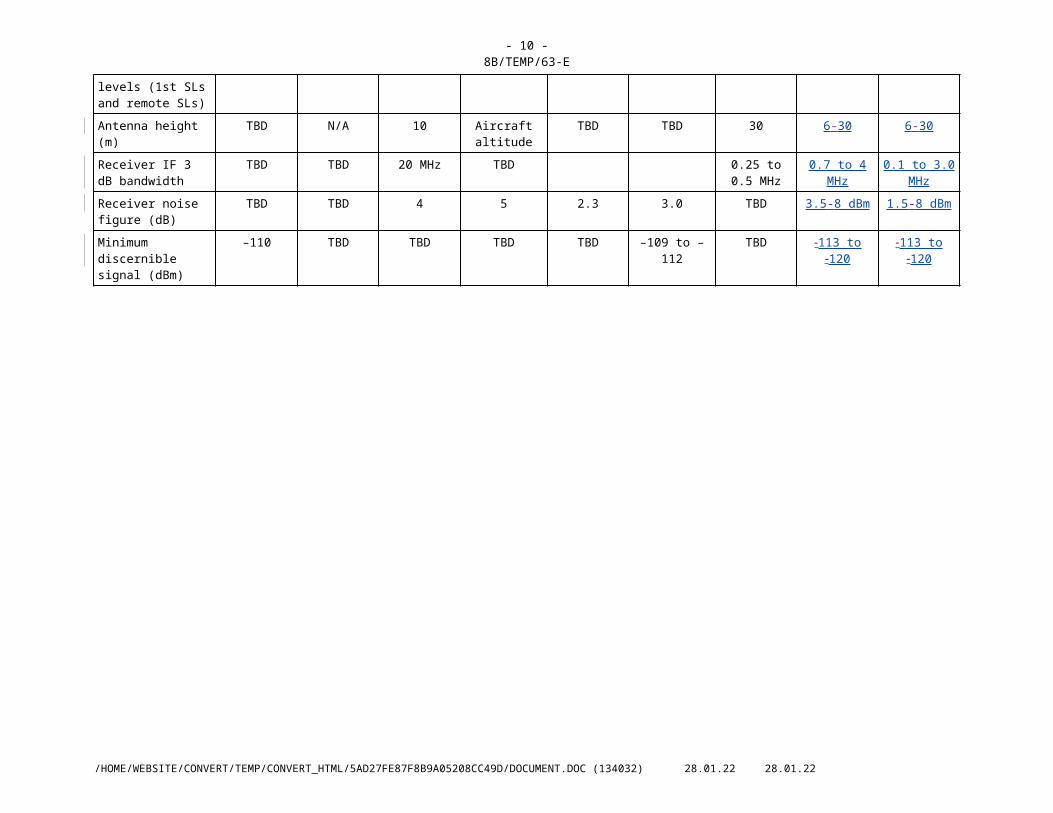
Antenna height (m) TBD N/A 10 Aircraft altitude TBD TBD 30 6-30 6-30
Receiver IF 3 dB bandwidth
TBD TBD 20 MHz TBD 0.25 to 0.5 MHz
0.7 to 4 MHz 0.1 to 3.0 MHz
Receiver noise figure (dB)
TBD TBD 4 5 2.3 3.0 TBD 3.5-8 dBm 1.5-8 dBm
Minimum discernible signal (dBm)
–110 TBD TBD TBD TBD –109 to –112 TBD 113 to 120 113 to 120
/TT/FILE_CONVERT/5AD27FE87F8B9A05208CC49D/DOCUMENT.DOC (134032) 07.05.23 07.05.23
- 9 -8B/TEMP/63-E
TABLE 2
Characteristics of radiolocation systemsCharacteristics Radar J
Radar HRadar KRadar I Radar LRadar J Radar K
Radar MRadar LRadar N
Radar ORadar M
Radar PRadar N
Radar ORadar Q
Function Instrumentation Instrumentation Instrumentation Instrumentation Instrumentation Surface and air search
Surface and air search
Research and Earth Imaging
Platform type (airborne, shipborne, ground)
Ground Ground Ground Ground Ground Ship Ship Airborne
Tuning range (MHz) 5 300 5 350-5 850 5 350-5 850 5 400-5 900 5 400-5 900 5 300 5 450-5 825 5 300
Modulation N/A None None Pulse/chirp pulse
Chirp pulse Linear FM None Non-linear/ Linear FM
Tx power into antenna 250 kW 2.8 MW 1.2 MW 1.0 MW 165 kW 360 kW 285 kW 1 or 16 kW
Pulse width (s) 1.0 0.25, 1.0, 5.0 0.25, 0.5, 1.0 0.25-1 (plain)3.1-50 (chirp)
100 20.0 0.1/0.25/1.0 7 or 8
Pulse rise/fall time (s) TBD TBD TBD TBD TBD TBD 0.03/0.05/0.1 TBD
Pulse repetition rate (pps) 3 000 160, 640 160, 640 20-1 280 320 500 2 400/1 200/750
TBD
Chirp bandwidth (MHz) N/A N/A N/A 4.0 8.33 1.5 N/A TBD
RF emission bandwidth –3 dB–20 dB
TBD TBD TBD TBD TBD TBD 5.0/4.0/1.216.5/12.5/7.0
TBD
Antenna pattern type (pencil, fan, cosecant-squared, etc.)
Pencil Pencil Pencil TBD TBD TBD Fan Fan
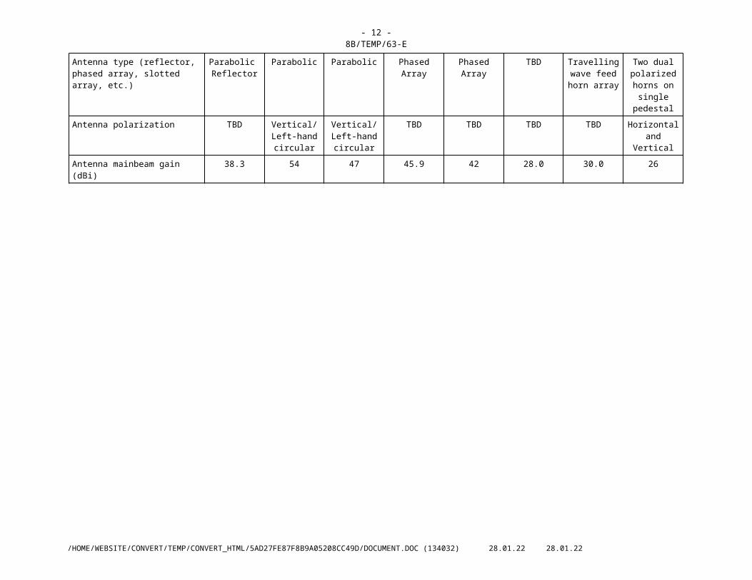
Antenna type (reflector, phased array, slotted array, etc.)
Parabolic Reflector
Parabolic Parabolic Phased Array Phased Array TBD Travelling wave feed horn
array
Two dual polarized horns
on single pedestal
Antenna polarization TBD Vertical/Left-hand circular
Vertical/Left-hand circular
TBD TBD TBD TBD Horizontal and Vertical
Antenna mainbeam gain (dBi) 38.3 54 47 45.9 42 28.0 30.0 26
/TT/FILE_CONVERT/5AD27FE87F8B9A05208CC49D/DOCUMENT.DOC (134032) 07.05.23 07.05.23
- 10 -8B/TEMP/63-E
TABLE 2 (CONTINUED)
Characteristics Radar HRadar J
Radar IRadar K Radar JRadar L Radar KRadar M
Radar LRadar N
Radar MRadar O
Radar NRadar P
Radar ORadar Q
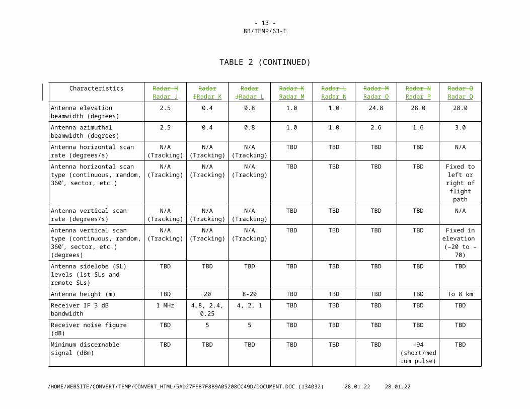
Antenna elevation beamwidth (degrees)
2.5 0.4 0.8 1.0 1.0 24.8 28.0 28.0
Antenna azimuthal beamwidth (degrees)
2.5 0.4 0.8 1.0 1.0 2.6 1.6 3.0
Antenna horizontal scan rate (degrees/s)
N/A (Tracking) N/A (Tracking) N/A (Tracking) TBD TBD TBD TBD N/A
Antenna horizontal scan type (continuous, random, 360, sector, etc.)
N/A (Tracking) N/A (Tracking) N/A (Tracking) TBD TBD TBD TBD Fixed to left or right of flight
path
Antenna vertical scan rate (degrees/s) N/A (Tracking) N/A (Tracking) N/A (Tracking) TBD TBD TBD TBD N/A
Antenna vertical scan type (continuous, random, 360, sector, etc.) (degrees)
N/A (Tracking) N/A (Tracking) N/A (Tracking) TBD TBD TBD TBD Fixed in elevation
(–20 to –70)
Antenna sidelobe (SL) levels (1st SLs and remote SLs)
TBD TBD TBD TBD TBD TBD TBD TBD
Antenna height (m) TBD 20 8-20 TBD TBD TBD TBD To 8 km
Receiver IF 3 dB bandwidth 1 MHz 4.8, 2.4, 0.25 4, 2, 1 TBD TBD TBD TBD TBD
Receiver noise figure (dB) TBD 5 5 TBD TBD TBD TBD TBD
Minimum discernable signal (dBm) TBD TBD TBD TBD TBD TBD –94 (short/medium
pulse)–102 (wide
pulse)
TBD
/TT/FILE_CONVERT/5AD27FE87F8B9A05208CC49D/DOCUMENT.DOC (134032) 07.05.23 07.05.23
- 11 -8B/TEMP/63-E
3 Operational characteristics
3.1 Meteorological radars
Both airborne and ground-based meteorological radars operate within the frequency range 5 250-5 850 MHz, the technical characteristics of which are given in Table 1.
The ground-based weather radar systems are used for flight planning activities and are often collocated at airports worldwide, to provide accurate weather conditions for aircraft. Therefore, these radars are also in operation continuously 24 hours per day.
Some mMeteorological radars operating in this band useprovide quantitative area precipitation measurements and in most cases belong to networks which coordinate such measurements over national or regional areas. Those which use Doppler radar technology toalso observe precipitation velocity, which indicates the presence and calculate the speed and direction of motion of severe weather elements such as tornadoes, hurricanes and violent thunderstorms as well as windshear and turbulence. Meteorological radars also provide quantitative area precipitation measurements so important inQuantitative measurements from both kinds of radar are used in real time as a critical and unique data source for hydrological, meteorological and environmental forecasting. of potentialThrough numerical data assimilation, modelling and forecasting of weather, flooding and pollution, particularly on the occasion of damaging events, the data are used to. The severe weather and motion detection capabilities offered by these radars contribute toward an increase in the accuracy and timeliness of forecasts and warnings services. The data may be used directly, for example to assess lightning risk. Many applications can be critical to safety and protection of the general public (both life and property) and the safety and security of military operations.
The airborne meteorological radars are used for both hurricane research and reconnaissance. The aircraft penetrate the eyewall repeatedly at altitudes up to 20 000 feet and as low as 1 500 feet. The aircraft collect research-mission data critical for computer models that predict hurricane intensity and landfall. Other aircraft penetrate hurricanes at higher, less turbulent altitudes (30 000-45 000 feet) to determine the position of the hurricane eye.
3.2 Aeronautical radionavigation radars
Radars operating in the aeronautical radionavigation service in the frequency band 5 350-5 460 MHz are primarily airborne systems used for flight safety. Both weather detection and avoidance radars, which operate continuously during flight, as well as windshear detection radars, which operate automatically whenever the aircraft descends below 2 400 feet, are in use. Both radars have similar characteristics and are principally forward-looking radars which scan a volume around the aircrafts flight path. These systems are automatically scanned over a given azimuth and elevation range, and are typically manually (mechanically) adjustable in elevation by the pilot (who may desire various elevation "cuts" for navigational decision-making).
3.3 Radiolocation radars
There are numerous radar types, accomplishing various missions, operating within the radiolocation service throughout the range 5 250-5 850 MHz. Table 2 gives the technical characteristics for several representative types of radars that use these frequencies that can be used to assess the compatibility between radiolocation radars and systems of other services. The operational use of these radars is briefly discussed in the following text.
Test range instrumentation radars are used to provide highly accurate position data on space launch vehicles and aeronautical vehicles undergoing developmental and operational testing. These radars are typified by high transmitter powers and large aperture parabolic reflector antennas with very narrow pencil beams. The radars have autotracking antennas which either skin track or beacon track
/TT/FILE_CONVERT/5AD27FE87F8B9A05208CC49D/DOCUMENT.DOC (134032) 06.11.01 29.10.01
- 12 -8B/TEMP/63-E
the object of interest. (Note that radar beacons have not been presented in the Tables; they normally are tuneable over 5 400-5 900 MHz, have transmitter powers in the range 50-200 Watts peak, and serve to rebroadcast the received radar signal.) Periods of operation can last from minutes up to 4-5 hours, depending upon the test program. Operations are conducted at scheduled times 24 hours/day, 7 days/week.
Shipboard sea and air surveillance radars are used for ship protection and operate continuously while the ship is underway as well as entering and leaving port areas. These surveillance radars usually employ moderately high transmitter powers and antennas which scan electronically in elevation and mechanically a full 360 degrees in azimuth. Operations can be such that multiple ships are operating these radars simultaneously in a given geographical area.
Other special-purpose radars are also operated in the band 5 250-5 850 MHz. Radar OQ (Table 2) is an airborne synthetic aperture radar which is used in land-mapping and imaging, environmental and land-use studies, and other related research activities. It is operated continuously at various altitudes and with varying look-down angles for periods of time up to hours in duration which depends upon the specific measurement campaign being performed.
4 Protection criteriaThe desensitizing effect on radars operated in this band from other services of a CW or noise-like type modulation is predictably related to its intensity. In any azimuth sectors in which such interference arrives, its power spectral density can simply be added to the power spectral density of the radar receiver thermal noise, to within a reasonable approximation. If power spectral density of radar-receiver noise in the absence of interference is denoted by N0 and that of noise-like interference by I0, the resultant effective noise power spectral density becomes simply I0 N0. An increase of about 1 dB for the [meteorological and ]radiolocation radar[s] would constitute significant degradation. Such an increase corresponds to an (I N)/N ratio of 1.26, or an I/N ratio of about –6 dB. For the radionavigation service [and meteorological radars], considering the safety-of-life function, an increase of about 0.5 dB would constitute significant degradation. Such an increase corresponds to an (I+N)/N ratio of about –10 dB. These protection criteria represent the aggregate effects of multiple interferers, when present; the tolerable I/N ratio for an individual interferer depends on the number of interferers and their geometry, and needs to be assessed in the course of analysis of a given scenario.
The aggregation factor can be very substantial in the case of certain communication systems, in which a great number of stations can be deployed.
The effect of pulsed interference is more difficult to quantify and is strongly dependent on receiver/processor design and mode of operation. In particular, the differential processing gains for valid-target return, which is synchronously pulsed, and interference pulses, which are usually asynchronous, often have important effects on the impact of given levels of pulsed interference. Several different forms of performance degradation can be inflicted by such desensitization. Assessing it will be an objective for analyses of interactions between specific radar types. In general, numerous features of radiodetermination radars can be expected to help suppress low-duty cycle pulsed interference, especially from a few isolated sources. Techniques for suppression of low-duty cycle pulsed interference are contained in Recommendation ITU-R M.1372 - Efficient use of the radio spectrum by radar stations in the radionavigation service.
/TT/FILE_CONVERT/5AD27FE87F8B9A05208CC49D/DOCUMENT.DOC (134032) 06.11.01 29.10.01
- 13 -8B/TEMP/63-E
5 Interference mitigation techniquesIn general, mutual compatibility between radiolocation, aeronautical radionavigation and meteorological radars is fostered by the scanning of the antenna beams, which limits main-beam couplings. Additional mitigation is afforded by differences between the waveforms of the two types of radars and the associated rejection of undesired pulses via receiver filtering and signal processing techniques such as limiting, sensitivity time control and signal integration. Additionally, interference can be mitigated by separation in carrier frequency or discrimination in time. In radar-to-radar interactions, separation in frequency is not always necessary for compatible operation because high degrees of isolation in power coupling and in time either occur naturally or can be achieved by good design. Additional details of interference mitigation techniques employed by radar systems are contained in Recommendation ITU-R M.1372 and PDR [8B/72].
____________
/TT/FILE_CONVERT/5AD27FE87F8B9A05208CC49D/DOCUMENT.DOC (134032) 06.11.01 29.10.01


![A comparison of single-cell trajectory inference methods ... · BGP 01/08/2017 Bifurcation TBD TBD TBD Noj [57] scanpy 09/08/2017 Bifurcation TBD TBD TBD Noj [58] B-RGPs 01/09/2017](https://img.pdfslide.us/doc/110x75/5faef63686c74474a31efbdd/a-comparison-of-single-cell-trajectory-inference-methods-bgp-01082017-bifurcation.jpg)