Embed Size (px)
Citation preview
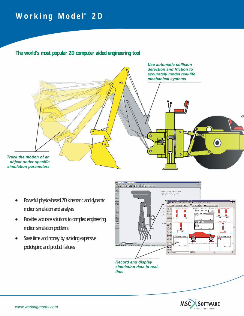
Track the motion of anobject under specific
simulation parameters
Use automatic collisiondetection and friction toaccurately model real-lifemechanical systems
Record and display simulation data in real-time
W o r k i n g M o d e l ® 2 D
The world’s most popular 2D computer aided engineering tool
•• Powerful physics-based 2D kinematic and dynamic
motion simulation and analysis
•• Provides accurate solutions to complex engineering
motion simulation problems
•• Save time and money by avoiding expensive
prototyping and product failures
www.workingmodel.com
SUPPORTED 2D FORMAT
DXF file format
BODY PROPERTIES & FEATURES
• Body types: circle, box, polygon and smooth (b-Spline edges)
• Mass, density, geometry, center of mass, moment of inertia, velocity and angular velocity, electrostatic charge and more
• Track the motion path of a body
• Automatic collision detection and response
• Automatically applied static and kinetic friction
CONSTRAINTS
• Pin, rigid, slot, keyed slot and curved slot joints
• Rods, ropes, pulleys and gears
• Linear and rotational spring/damper
MOTION DRIVERS
• Motor
• Actuator
• Force
• Torque
Constraints and drivers can be defined bynumeric or equation input in the formulaeditor, or with tabular data.
UNITS SYSTEMS & FORMULAS
SI, English, CGS and user-defined
MEASURABLE PARAMETERS
• Position
• Velocity
• Acceleration
• Momentum
• Angular momentum
• Constraint force and torque
• Gravity, electrostatic and air force
• Kinetic energy, gravitational potential energy and power
Record and display simulation data in real-timewith graphical and digital meters.
SIMULATION CONTROL
Run, stop, reset, single step, or pause the simulation at any time.
Control the accuracy of your simulation bymodifying integration and animation steps and configuration tolerances.
Superimpose multiple simulations.
INTERACTIVE CONTROLS
• DDE connection to Excel and MatLab
• Complete “Visual Basic” style scripting language with built-in debugger
• Menu and script buttons
• “Player” mode for content creation
VISUALIZATION
• Track the motion path of a body or its center of mass
• Attach graphics to bodies
• Images on bodies rotate
• Display system center of mass
• Multiple, moving reference frames
SCRIPTS
• Optimize
• Create constraint
• Document model
• Zoom to extents
• Measure distance between points
• Flip polygon
• Multiple file run
• Pin friction
• Slot friction
• Slot damper
• Flexbeam
• Shear and bending moment
OUTPUT
• AVI video files for playback
• Meter data from simulations to
tabular data file
PRINTING
• Print an image of your simulation or
meter data
WORKING MODEL 2DSYSTEM REQUIREMENTS
• Microsoft Windows NT® 4.0 or
Windows 95/98/Me/2000/XP
• Pentium PC
• 16MB RAM Minimum
• Video card and monitor capable
of at least 16-bit color
• CD-ROM Drive
MSC.Software
66 Bovet Road, Suite 200
San Mateo, CA 94402
800-766-6615, 650-574-7777
fax: 650-574-7541
Nastran is a registered trademark of NASA. MSC and Working Model are registered trademarks and MSC.Nastran and MSC.Software are trademarks of MSC.Software Corporation. All other trademarks are the property of their registered owners. ©2001 MSC.Software Corporation.
www.workingmodel.com
Working Model 2D Features

MSC.Software Tel. 800.766.6615 Fax. 650.574.7541 http://www.workingmodel.com
1
Welcome to Working Model Working Model is the result of a twelve-year collaborative effort between professional engineers and software specialists. We are committed to providing you easy-to-use, engineering software that makes you more productive, and saves time and money on hardware prototyping, testing, and redesigns. To get started, install Working Model and go through each step of the demonstration described below. If you have any questions, please call us toll-free at 800.766.6615
1.0 Installing Working Model 1. Insert the enclosed CD into the CD-Rom drive and follow the installation instructions 2. When prompted for a serial number, type “DEMO”
3. When the “Choose Folder” window appears, click [OK]. 4. For a step-by-step introductory tutorial, turn to the next page.
2
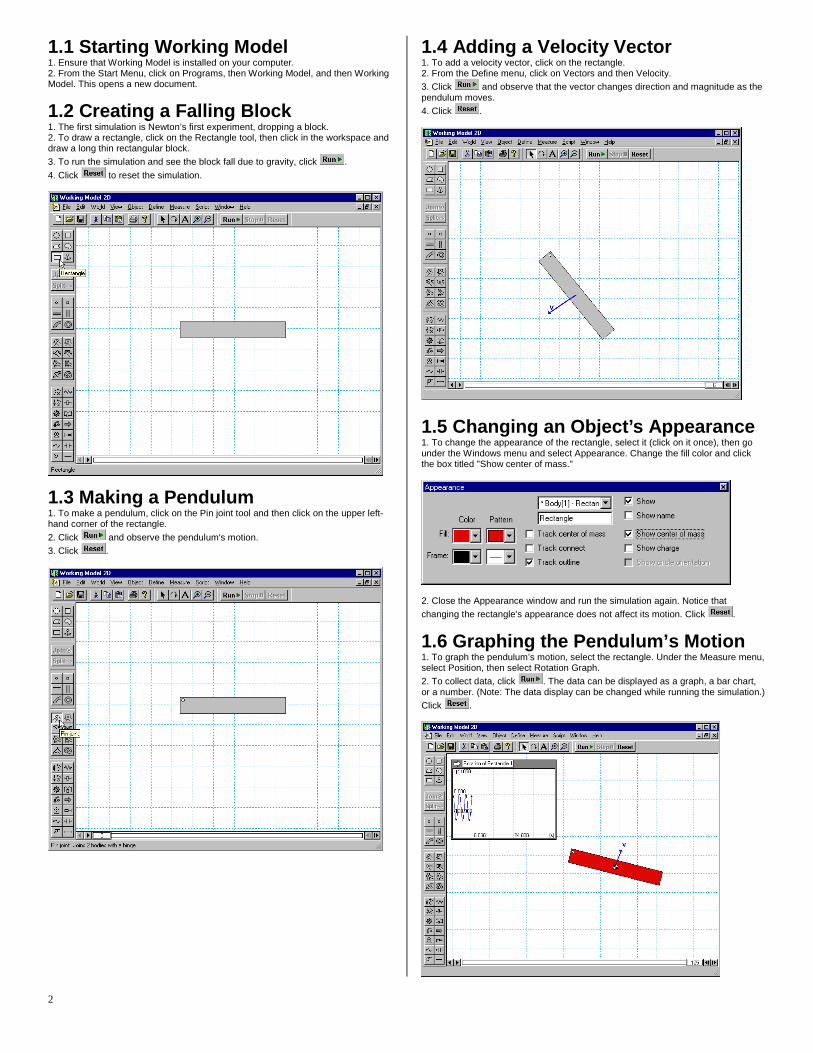
1.1 Starting Working Model 1. Ensure that Working Model is installed on your computer. 2. From the Start Menu, click on Programs, then Working Model, and then Working Model. This opens a new document.
1.2 Creating a Falling Block 1. The first simulation is Newton’s first experiment, dropping a block. 2. To draw a rectangle, click on the Rectangle tool, then click in the workspace and draw a long thin rectangular block.
3. To run the simulation and see the block fall due to gravity, click .
4. Click to reset the simulation.
1.3 Making a Pendulum 1. To make a pendulum, click on the Pin joint tool and then click on the upper left-hand corner of the rectangle.
2. Click and observe the pendulum's motion.
3. Click .
1.4 Adding a Velocity Vector 1. To add a velocity vector, click on the rectangle. 2. From the Define menu, click on Vectors and then Velocity.
3. Click and observe that the vector changes direction and magnitude as the pendulum moves.
4. Click .
1.5 Changing an Object’s Appearance 1. To change the appearance of the rectangle, select it (click on it once), then go under the Windows menu and select Appearance. Change the fill color and click the box titled "Show center of mass."
2. Close the Appearance window and run the simulation again. Notice that
changing the rectangle's appearance does not affect its motion. Click .
1.6 Graphing the Pendulum’s Motion 1. To graph the pendulum’s motion, select the rectangle. Under the Measure menu, select Position, then select Rotation Graph.
2. To collect data, click . The data can be displayed as a graph, a bar chart, or a number. (Note: The data display can be changed while running the simulation.)
Click .
3
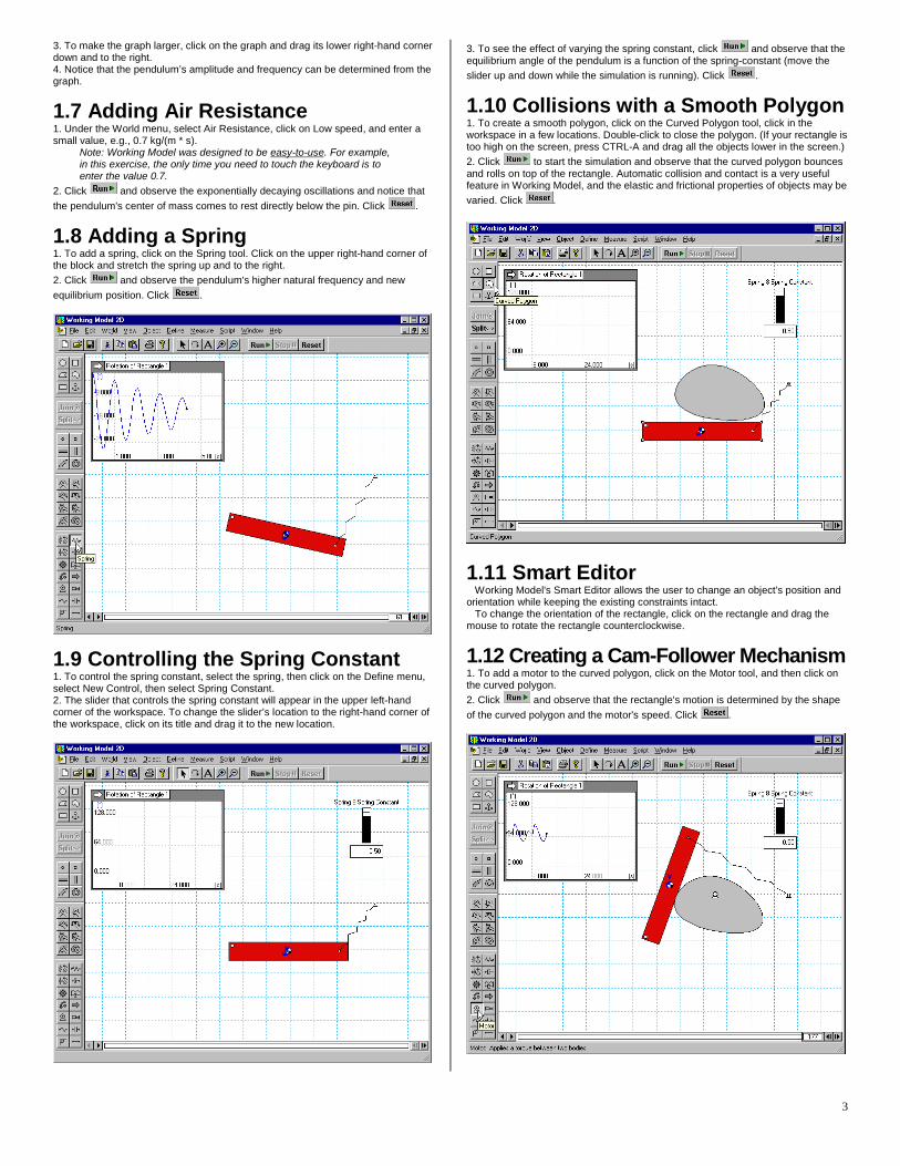
3. To make the graph larger, click on the graph and drag its lower right-hand corner down and to the right. 4. Notice that the pendulum’s amplitude and frequency can be determined from the graph.
1.7 Adding Air Resistance 1. Under the World menu, select Air Resistance, click on Low speed, and enter a small value, e.g., 0.7 kg/(m * s).
Note: Working Model was designed to be easy-to-use. For example, in this exercise, the only time you need to touch the keyboard is to enter the value 0.7.
2. Click and observe the exponentially decaying oscillations and notice that
the pendulum's center of mass comes to rest directly below the pin. Click .
1.8 Adding a Spring 1. To add a spring, click on the Spring tool. Click on the upper right-hand corner of the block and stretch the spring up and to the right.
2. Click and observe the pendulum's higher natural frequency and new
equilibrium position. Click .
1.9 Controlling the Spring Constant 1. To control the spring constant, select the spring, then click on the Define menu, select New Control, then select Spring Constant. 2. The slider that controls the spring constant will appear in the upper left-hand corner of the workspace. To change the slider’s location to the right-hand corner of the workspace, click on its title and drag it to the new location.
3. To see the effect of varying the spring constant, click and observe that the equilibrium angle of the pendulum is a function of the spring-constant (move the
slider up and down while the simulation is running). Click .
1.10 Collisions with a Smooth Polygon 1. To create a smooth polygon, click on the Curved Polygon tool, click in the workspace in a few locations. Double-click to close the polygon. (If your rectangle is too high on the screen, press CTRL-A and drag all the objects lower in the screen.)
2. Click to start the simulation and observe that the curved polygon bounces and rolls on top of the rectangle. Automatic collision and contact is a very useful feature in Working Model, and the elastic and frictional properties of objects may be
varied. Click .
1.11 Smart Editor Working Model's Smart Editor allows the user to change an object's position and orientation while keeping the existing constraints intact. To change the orientation of the rectangle, click on the rectangle and drag the mouse to rotate the rectangle counterclockwise.
1.12 Creating a Cam-Follower Mechanism 1. To add a motor to the curved polygon, click on the Motor tool, and then click on the curved polygon.
2. Click and observe that the rectangle's motion is determined by the shape
of the curved polygon and the motor's speed. Click .
4
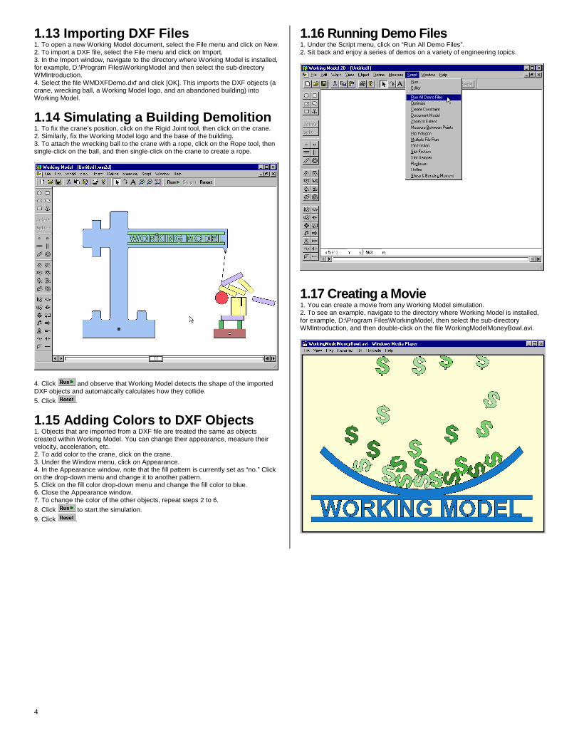
1.13 Importing DXF Files 1. To open a new Working Model document, select the File menu and click on New. 2. To import a DXF file, select the File menu and click on Import. 3. In the Import window, navigate to the directory where Working Model is installed, for example, D:\Program Files\WorkingModel and then select the sub-directory WMIntroduction. 4. Select the file WMDXFDemo.dxf and click [OK]. This imports the DXF objects (a crane, wrecking ball, a Working Model logo, and an abandoned building) into Working Model.
1.14 Simulating a Building Demolition 1. To fix the crane’s position, click on the Rigid Joint tool, then click on the crane. 2. Similarly, fix the Working Model logo and the base of the building. 3. To attach the wrecking ball to the crane with a rope, click on the Rope tool, then single-click on the ball, and then single-click on the crane to create a rope.
4. Click and observe that Working Model detects the shape of the imported DXF objects and automatically calculates how they collide.
5. Click .
1.15 Adding Colors to DXF Objects 1. Objects that are imported from a DXF file are treated the same as objects created within Working Model. You can change their appearance, measure their velocity, acceleration, etc. 2. To add color to the crane, click on the crane. 3. Under the Window menu, click on Appearance. 4. In the Appearance window, note that the fill pattern is currently set as “no.” Click on the drop-down menu and change it to another pattern. 5. Click on the fill color drop-down menu and change the fill color to blue. 6. Close the Appearance window. 7. To change the color of the other objects, repeat steps 2 to 6.
8. Click to start the simulation.
9. Click .
1.16 Running Demo Files 1. Under the Script menu, click on “Run All Demo Files”. 2. Sit back and enjoy a series of demos on a variety of engineering topics.
1.17 Creating a Movie 1. You can create a movie from any Working Model simulation. 2. To see an example, navigate to the directory where Working Model is installed, for example, D:\Program Files\WorkingModel, then select the sub-directory WMIntroduction, and then double-click on the file WorkingModelMoneyBowl.avi.
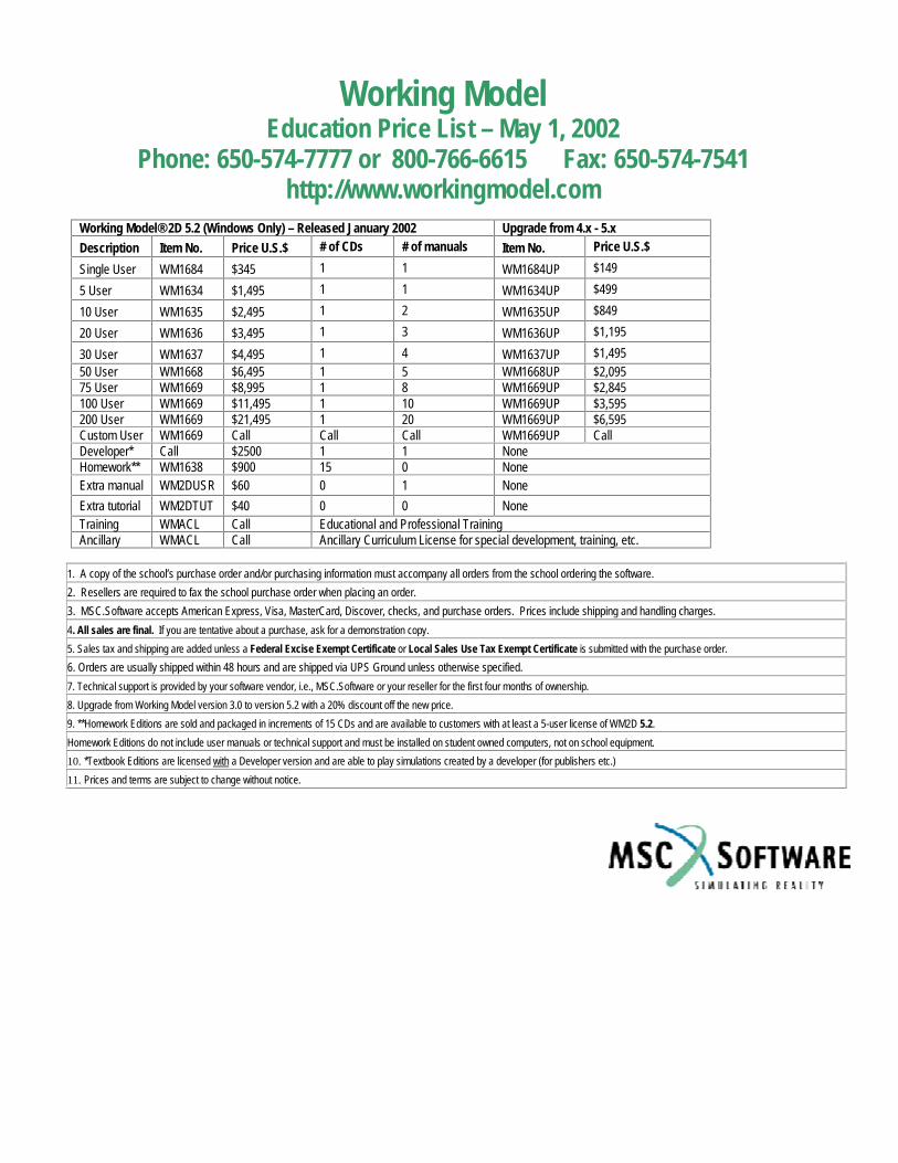
Working Model Education Price List – May 1, 2002
Phone: 650-574-7777 or 800-766-6615 Fax: 650-574-7541 http://www.workingmodel.com
Working Model® 2D 5.2 (Windows Only) – Released January 2002 Upgrade from 4.x - 5.x
Description� Item No.� Price U.S.$� # of CDs � # of manuals � Item No.� Price U.S.$ �Single User� WM1684� $345� 1 � 1 � WM1684UP� $149 �5 User� WM1634� $1,495� 1 � 1 � WM1634UP� $499 �10 User� WM1635� $2,495� 1 � 2 � WM1635UP� $849 �20 User� WM1636� $3,495� 1 � 3 � WM1636UP� $1,195 �30 User� WM1637� $4,495� 1 � 4 � WM1637UP� $1,495 �50 User � WM1668 � $6,495 � 1 � 5 � WM1668UP � $2,095 �75 User � WM1669 � $8,995 � 1 � 8 � WM1669UP � $2,845 �100 User � WM1669 � $11,495 � 1 � 10 � WM1669UP � $3,595 �200 User � WM1669 � $21,495 � 1 � 20 � WM1669UP � $6,595 �Custom User � WM1669 � Call � Call � Call � WM1669UP � Call �Developer* � Call � $2500� 1 � 1 � None �Homework** � WM1638 � $900� 15 � 0 � None �Extra manual � WM2DUSR � $60 � 0 � 1 � None �Extra tutorial WM2DTUT $40 0 0 None Training � WMACL � Call � Educational and Professional Training �Ancillary � WMACL � Call � Ancillary Curriculum License for special development, training, etc. �
1. A copy of the school’s purchase order and/or purchasing information must accompany all orders from the school ordering the software.�2. Resellers are required to fax the school purchase order when placing an order.
3. MSC.Software accepts American Express, Visa, MasterCard, Discover, checks, and purchase orders. Prices include shipping and handling charges.�4. All sales are final. If you are tentative about a purchase, ask for a demonstration copy.
5. Sales tax and shipping are added unless a Federal Excise Exempt Certificate or Local Sales Use Tax Exempt Certificate is submitted with the purchase order.�6. Orders are usually shipped within 48 hours and are shipped via UPS Ground unless otherwise specified.�7. Technical support is provided by your software vendor, i.e., MSC.Software or your reseller for the first four months of ownership.�8. Upgrade from Working Model version 3.0 to version 5.2 with a 20% discount off the new price.
9. **Homework Editions are sold and packaged in increments of 15 CDs and are available to customers with at least a 5-user license of WM2D 5.2.�Homework Editions do not include user manuals or technical support and must be installed on student owned computers, not on school equipment.�10. *Textbook Editions are licensed with a Developer version and are able to play simulations created by a developer (for publishers etc.)�11. Prices and terms are subject to change without notice.