Embed Size (px)
Citation preview

Worked Examples of The Use of OpenFX
A series of worked examples are provided for some commonly used animations. They illustrate some of the core ideas that can be used in a number of different scenarios:
• Tutorial 1 - Making a flying logo animation • Tutorial 2 - Basic Ideas of Morphing
Tutorial 1: Making your own "Universal" flying logo
Introduction
The animation presets in OpenFX make it very easy to make your own flying logo to mimic the "Universal Movie Studio's Logo". The greatest difficulty in making this animation is not in the modelling, it's not even in the animating, if there is any difficulty it lies only in fact that each character in the name must be stored in a separate MFX (scene) file and organising the location of where these are stored should be decided in advance of making the animation. In this tutorial we will gather all the files for the project is a new directory located on Drive E: (you may put them elsewhere - it's up to you).
In this exercise the "Logo" I will animate is the expression "BALANCED-EXCELLENCE"
Getting the bits and pieces
We need is an image map of the surface of the earth and possibly a starfield backdrop, however the starfield plugin of OpenFX will suffice. We also need either a Postscript or TrueType font from which we will model the text.
To prepare for the project use Windows Explorer to create a new project directory on drive E: I will call mine "project2":

Into this directory I will place two image maps that I need to use. The first is a mecator projection of an artists impression of the surface of a cloudless earth and the second is an image that I will use as a reflection map during the modelling process. The are simply called. MECATOR.GIF and PLANET.GIF
There are two main parts to making a OpenFX animation:
1. Modelling 2. Animating
We will start with the modelling - making models of the "Earth" and the "String of Text" that has to fly round it. After that we will use one of OpenFX's template animations to do most of the work for us. A little bit of tidying up by hand will complete the task.
Modelling
Stage 1: Build the model of the earth by simply applying a map "(Mecator Projection preferable)" to a simple spherical primitive. To make the sphere call up the Primitives Dialog (Menu Build/Build Primitives - or press F7):
You can make several types of spheres - we suggest a Lat Sphere with 18 lines of latitude and 24 lines of longitude. This is a good choice for a sphere on which we will bas a model of the Earth.
When you press the make button the SFX Modeller window will look like:

Next an image map must be painted onto our putative globe: We will use the map below, called MECATOR.GIF which has been imported into folder "project2" on drive E:
There are three stages in mapping:
1. Make the image Map 2. Align it to the model 3. Apply it to the selected faces.
Mapping Stage1 Before calling up the Map Dialog Box make sure that the "Front" view window is active (A Yellow outline is drawn round the active view window (see picture above - the top window has the yellow outline) if the Front window is not active then clicking the mouse in the window activates it - our you could press the TAB key until the window becomes active. Now call up the map dialog. (Menu: Attributes/Map/Edit Map...) You will be asked to select the map you wish to edit. For a new project there is only one map so just click on OK. After this the Mapping dialog pops up:

In this Dialog you will see a large number of buttons, sliders and check boxes. We will only need to make three modifications to the default settings. For our model of the surface of the Earth we need to apply a surface map. This is done by clicking in the checkbox labelled (1) above. After this a File Open dialog will pop up and we select the MECATOR.GIF image map. When the Open button is clicked the name of the map appears in the window (labelled 2 above) and some of the other buttons that were greyed out become active.
The third action we need to take concerns the way in which the map will be applied onto the surfaces to which it is assigned. There are 4 options (the 4 image buttons) - Since we are applying a flat map originally taken from a spherical model (the mecator projection) the ideal choice is the "Spherical" mapping method. So click on the image button labelled (3). These are all the changes you need to make to this dialog so now we can proceed to align the map to the faces on which we wish to apply it. So click on the "Move" button at the top of the dialog.
Mapping Stage 2 This hides the dialog and returns us to the main Window Box views with an additional Tool Palette Labelled "Lock" floating above the window. In the windows you can also a representation of our Spherical map, at (1) and (2) in the figure below:
The representation of a "Spherical Map" type looks similar to that of a "Cylindrical Map" However there are a few differences. The Little rectangle at the centre of the circle in the TOP

window and at the top left corner of the map representation in the Front window (labelled 2) corresponds to the centre of the sphere on which the spherical map is based. The Upside down triangle and small dot, which are the other two map control points, server only to align the map. In the case of our model of the earth we must drag the rectangle into the centre of the sphere there is no need to move either of the other control points.
Therefore all that needs to be done is first to click on the Rectangle in the Top view window and drag it to the centre of the wireframe sphere. Then do the same thing in the front window so that it is located at the centre of the sphere as shown below. The rectangle lies at the points labelled (1) and (2) below. You can also click and drag the "Triangle" so that it lies at the location labelled (3) below.
Once you are happy with the alignment of the map click the "Done" button in the popup up tool panel to return to the Mapping Dialog. Simply press the "Done" button and proceed to the next step.
Let's recap; at this stage we have a spherical model of vertices and faces and an image map that is aligned around the sphere. What we must now do is apply the image map to the faces of the sphere. By doing this we will see the effect of out mapping when the an image of the model is rendered. We need to apply the map to ALL the faces in the sphere - so make sure all faces in it are selected (i.e. they show up as yellow dots).
Mapping Stage 3 Now call up the Attributes Dialog, (Menu Attributes/Material Settings... or press the F8 key). A "Tabbed" dialog appears click on the "Maps" tab to reveal the page relevant for mapping the currently selected faces. (The title of the dialog indicates the number of faces that are selected).
Click the "Set" and when the Map Selector Dialog pops up choose our map (If you did not enter a specific name for the map it will, by default, take the name "unnamed_1". (This is button labelled (1) below):

You can leave the other button settings on this page at their default values. - Our model is now complete. Click the Preview button and you should get an image like this:
Click the "Close" button on the attributes dialog and save the model in a MFX file. Use the (Menu File/Save As...) command.and choose an appropriate name: EARTH.MFX
Stage2: Building the text. This stage consists of three phases:
1. Build the text string using the "Create Text" Tool of SFX's modeller. 2. Apply any mapping or textures to the models to get the finish you require. 3. Use the "Export Models" option to put each letter in your text into a separate "MFX"
file.
Balanced Excellence is a very poor expression for a tutorial because it is a very long expression (18 characters including a space), you will probably choose something shorter. However it does server to show how we deal with expression that contain multiple copies of the same letter.

Lets start with the Text Creation Dialog, to call it up click on the "Add Actor" toolbar button and select "True Type Text" from the pop up menu. The dialog below will appear after you select a suitable text font from the standard "Select Font Dialog Box":
The True Type Text builder dialog shows a preview of the selected font and has controls to enable you to build your text model in several styles. For our tutorial we have to adjust three of the parameters. In the figure above we first give the text some "depth" (i.e. make it look like it stands out, has some third dimension) Do this by increasing the width of the text with the "Width" slider (1). We will be manipulating each character in the text string individually so we need to set a "Hold Point" at the centre of the characters (press the radio button labelled (2) above). And finally we must enter our expression in the Text Box (item 3 above).
When this is done press the "Make" button and after a few seconds work you will have a 3D model in vertices, edges and faces of the expression "Balanced Excellence" (as shown below):

Note I changed the shape of the windows by clicking and dragging the edges to get display windows that more closely match the shape of the text model. Further note in the "View" window the blue colour of the sides of the text, it is the presence of these sides that give our model its 3D look.
The text builder function of SFX has given a Red colour to the font faces of the text and a blue colour to the side faces. We can get a more exciting look for our text if we make it shiny and partially reflective. For this we need to change the colour and create a reflection map.
To start bring up the Attributes dialog (below) (Menu Attributes/Material Settings...) (or F8) Click on the Colour Swatch (1) and choose an orangy colour, also click the "Shiny Hotspots" tick box (2):
Next switch to the Maps tab and click the "Set" button. As you haven't created any maps only the "new" map can be chosen. This "new" map is not as yet defined so after the selection dialog is dismissed click on the "Edit" button to bring up the maps dialog, as shown below:
For this map we will be using the reflection settings only so there is no need to position its axes. Reflections are generated automatically and depend on the global orientation of the model. To configure the reflection part of the map click the Tick Box (labelled 1) and choose a suitable reflection map. Once selected the named map is listed at (2) . In passing note the reflection setting of 50 on the slider. This setting means that surfaces to which the map is applied appear to be 50% reflective. The result we obtain is shown below:

Note the effect at 1 above, the mixture of surface colour and reflective map gives the sides of the text the illusion of being make of a gold like surface. The actual content of the reflection map is not terribly important, it is the fact that it contains some variation and some "overall" perception of a dominant colour that is important. (You can look at the map I used and see what I mean.)
With our model complete you should save it as a whole entity in case you want to return to it later to make some changes. It is very easy to make the separate models for each letter from the original - so keep a copy of it. (File/Save As..)
The modelling is nearly finished. We simply have to export each of the letters to a separate .MFX file. This process is automated with a special command: File/Export Model/Letters. On executing the command the following Dialog box pops out:
Since each letter is stored in its own file we only have to specify the folder(directory) into which the models are placed. Clicking OK puts each letter into a separate .MFX file. The names these MFX files take follow a rule that will enable us to easily identity which file corresponds to which letter. OpenFX is able to identify which letter is which because it uses an internal hierarchy to record which vertices and faces belong to which letter.
If we use the "Open Model Dialog" to look at the files we have just created we can see the "balanced_excellence.MFX" file and...
At (1) the file corresponding to the first capital B in the text string is indicated. Its name is B1-C. The second character (an "a") is stored in a file named "a2". So hopefully you can see the pattern. Each file is given a name that starts with the letter itself, then has a number appended 1 for the first character, 2 for the second, etc. etc. If the letter is a capital letter a "-C" is appended after that. A space character is given the name "space"
Basic Animation
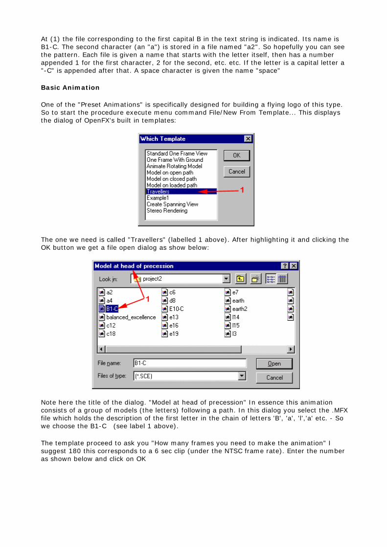
One of the "Preset Animations" is specifically designed for building a flying logo of this type. So to start the procedure execute menu command File/New From Template... This displays the dialog of OpenFX's built in templates:
The one we need is called "Travellers" (labelled 1 above). After highlighting it and clicking the OK button we get a file open dialog as show below:
Note here the title of the dialog. "Model at head of precession" In essence this animation consists of a group of models (the letters) following a path. In this dialog you select the .MFX file which holds the description of the first letter in the chain of letters 'B', 'a', 'l','a' etc. - So we choose the B1-C (see label 1 above).
The template proceed to ask you "How many frames you need to make the animation" I suggest 180 this corresponds to a 6 sec clip (under the NTSC frame rate). Enter the number as shown below and click on OK

The next question the "Travellers" template asks is what path to follow. A File Open dialog presents a list of saved paths. There are a number of default paths and you can build your own in the modeller if none of these are suitable for your requirement. For this example I choose a spiral path "Spiral.pth" (1) below:
Now we continue to add all the other models that represent the characters in the expression we are animating:
This step uses a number of File Open Dialogs to add the remaining models. Select each one in turn and click on "Open". After you have added the last one click on "Cancel" You can just choose them according to the sequence number: a2, l3 etc.etc.
After dismissing the last Open dialog OpenFX assembles the elements in the animation and the window box display will resemble the following:

In the screen shot above we see the Top and Front Window Box views. In them the spiral path is clearly visible at (1) it is less evident in the front view (but appears as a straight line at the bottom of the Front window).Also visible at (2) are the Bounding Boxes of each of the letters in the text. They look a little strange because they are very large in relation to the size of the spiral path that they will follow. Also this figure shows the state of play during frame 1 at the beginning of the animation so all the models overlap. If you like drag the slider below the Camera window to the end of the animation to see how these bounding boxes follow the path. (If you do this slide it back until frame 1 is again the current frame.
It should be obvious that we need to make the spiral path larger. This can be done easily by expanding it but before we can do that we must select it. In the animator a selected actor is drawn in yellow, the deselected actors appear light blue. To select an actor we click on its outline or in the case of paths; one of their control points (the rectangles - arrowed below). Click in the path control point and it will turn yellow:
With the path selected clink on the "Scale" tool (1 below) in the main tool panel. The path will be drawn in "inverse video colour" and a small floating tool palette (at 2) will pop up, ignore this for the moment. The path is scaled interactively by clicking in any of the view windows and dragging the mouse left or right, Dragging to the right expands the selected actor. Dragging to the left contracts the size. (Incidentally Double clicking on the tool Icon brings up a Dialog Box into which you can enter numerical expansion factors). After some experimentation you should be able to enlarge the path enough so that you can hardly see the letters bunched together at that start of the path. The path should look like that shown below at (3). At this stage you could also click ON and drag the Camera icon away from the scene until you get a suitable view in the Camera window:

For our next step we will make some minor modifications to the shape of the path using the control vertices on it. To do this we again start with the path selected. To edit the path we need to move into path edit mode. This is done by selecting the "Vertex" tool from the main tool palette at (1) below:
In path edit mode there are 4 actions that we can take and they are chosen from the small floating tool palette at (2). You can see the default action is Move and for now this is all we need so we can proceed to modify the path at (3) by moving its control vertices.
Carrying out any path modification requires two steps.
1. Select the path control point to be modified. 2. Move (or modify) it by clicking and dragging the mouse in one of the view windows.
To select a path control point Click (and release the left mouse button) while pointing the mouse at the control point. A selected control point is shown in a different colour from the other control points. To move the control point Click and drag the mouse (click anywhere in the view windows).

Now try moving the control point at the end of the path (3 above) to extend it slightly. When you are finished either choose the Actor Selector Tool from the panel or click the close button on the floating tool panel.
Our path and letters are now loaded. To complete setting up the animation we now must load the model of the Earth we completed earlier. This is simply done by using the "Insert" button from the main tool panel and choosing "Actor". A File Open dialogs for MFX files is presented and you should choose the EARTH.MFX file.
In the animator Window Box display the model for the earth is shown as a cubic bounding box, (at 1 below) click on any line to select it and you should have a display something like that shown below. (The picture below also includes a "Quickrendering into the Camera Window (F12)):
You may need to move the Earth a little - you can do this quickly by Clicking on its bounding box outline and dragging it to the position you think is best. You might also notice in the above a "Blue" background to the camera window - this is not what we want - but we will fix it up later. For the moment we will move on to make the Earth rotate about its axis.
Making the Earth perform one rotation during the animation is best accomplished by using an "Internal Rotation". To set this up we move on to the "Keyframer" which appears at the bottom of main window (in the area of arrows 2 and 3 above.) With the model for the Earth selected this shows the animation timelines for its action. In your display it is probably named 2Model-20" or some such. We can change this by clicking on the small black arrow at (2) this gives us a popup menu and by selecting the rename command we can give our model the much more descriptive name of "Earth". Now your display should resemble that above. If the coloured boxes at the end of the Keyframer (at 3) are not showing; drag the slider at the bottom of the Keyframes all the way to the right until they appear.
In the keyframer the timelines are clearly visible as coloured lines. The Green timeline ending at (3) is the rotation timeline. We change its properties by Double Clicking the rectangle at the end of the timeline (at 3). Hopefully this will bring to life the following timeline Dialog:

To set the Earth rotating all that must be done is to click the button labelled (1) above and dismiss the dialog by clicking OK.
Earlier I said we need to remove the un-space like blue background. In the animation a background is provided by the Sky actor so it is this we must change. To get at the dialog that controls the sky the simplest method is to being up the actor selection dialog (Press A) and double click on the one labelled Sky - it has a little cloud symbol:
To change the sky to the Jet black of outer space click on the Plain Sky button (1) and use the Colour Button (1) to select a black colour. In the next section we will see how to insert a starfield.
So that's it!!! I suggest you now save your work in a named .OFX file. All the basics are in place, we could render off our animation but at this stage we will settle for a wireframe preview. (Menu Frames/Wireframe Preview..)
Finishing Touches
To finish off the animation we will modify the camera's "Size" to achieve the effect of it zooming in on our "Balanced Excellence". In OpenFX the Size timeline in the Keyframer controls the setting of the Camera's zoom lens. If the camera is not selected click on it, so that it turns yellow. In the keyframer window you should be able to see the timelines for the camera as shown below:

The size timeline lies at the bottom of the timelines and is coloured "Red" It has one keyframe (red rectangle) at the end of the animation. (At 2 above). In order to obtain a 2zooming" effect we need to add a second keyframe to this timeline. I have chosen to put this at frame 145. A keyframe is introduced at any point in a timeline by clicking on that timeline. Move the mouse to frame 145 (A vertical "indicator" follows the cursor and the Status bar at the bottom of the window tells you which frame is currently active). This is point labelled (1) above.
If you double-click on either of these keyframe you will get the camera settings dialog (below) into which you can enter setting for the camera lens. (The diagram below applies to the keyframe at (1) above i.e. for frames 1 to 145. Don't alter the stetting just press the OK button. We will adjust the degree of camera zoom interactively by using the Scale tool from the main tool panel.
To adjust the camera zoom setting - make sure the Camera is selected and the last frame in the animation is on display - click the scale button on the main tool bar (or press S). Now you can adjust the zoom setting on the camera by click-dragging the mouse to the left or right. You should see the camera's field of view narrow or widen and the effect on what the camera sees should be evident in the Camera window itself.
Once you have a setting you like dismiss the scaling tool by clicking on the actor selector (or just press 0).
Before rendering the animation there are a couple of further adjustments worth investigating. Firstly our scene is set against a backdrop of stars. So we will use an image post-processor to put in an actual starfield. We don't need the fine tuning that an Xip actor give us so an Image Processor applied to all frames is quite sufficient.
To set up a starfield for all frames execute the menu command Edit/Image Process All frames... The following dialog box pops up:

Click on ADD and choose "STARS.XFX" from the list in the File Open dialog. After the Stars parameter dialog pops up (below). Click on the "Data in File" radio button and press OK.
Close the Image Process All Frames dialog.
For our final trick we will alter the properties of the spiral path so that as the letters in our "Balanced Excellence" flying logo approach the end of the path - they slow down. This effect is achieved by altering the path velocity. To do this first select the path (click on one of its control points - our use the actor selection dialog (A)) - then execute the Menu Edit/Path Velocity command to display the following dialog:

By adding a couple of control points to the curve (at the red arrows above) you can instruct the models to slow down as they approach the end of the path.
Finally it only remains to render our project. Sit back and enjoy the "Balanced Excellence"
Tutorial 2: Morphing (Basic)
Introduction
To 'Morph' means literally to change form. In computer animation it is 'morphing' that helps up make the impossible possible. Movie and TV commercial makers use computer generated morphs to bring apparently inanimate objects to life. The dancing juice carton, facial expressions of animated characters and 'bendy' cars are all produced by morphing a basic shape.
In the context of computer animation software packages you start with a model of the basic shape or object and then use the tools of the software to distort it in to a number of 'key' shapes. Then during the animation phase the key shapes will be joined up to give a seamless change from one form (morph) to another.
An animator could use the morphing technique as the only method of animating the models in a virtual scene. However there are much more efficient ways of animating simple 'rigid' motion (i.e. keyframes for position, rotation, scale etc.). Even for the gross actions of articulated figures there are better ways to do it. A 'skeleton' around which a wireframe mesh is attached makes realistic motion much more readily attained. Add some 'mathematical musculature' and a lot of the drudgery required to set up all the 'key' morph shapes is avoided.
However there are cases were morphing is unavoidable and it often is the 'best' way to achieve some effects (the dancing juice carton in TV ads. is a prime example). An ideal computer animation package provides to its user all these different techniques.OpenFX indeed does this and in this tutorial we will look at the basic use of morphing. (Subsequent tutorials will look at Skeletons).
Basic Background
In the context of OpenFX morphing is heavily associated with the Modeller module. To animate the morphed shapes require simply the setting of a few switches in the Animator and the adjustment of at which time the key frames occur for the Costume timeline.
OpenFX supports two methods of morphing:
1. Topologically identical structures (Each morph has the same number of vertices) 2. Topologically dissimilar structures. (Each morph may have a different number of
vertices)
We will start by looking at type (1) morphing. However before getting in to details let's consider the basic fact:
All models are build from triangular facets attached to vertices positioned in space.
The facets (faces) give the surface attributes and are what is actually visualised. In the context of morphing we might want to change their colour or texture during the morph. The shape of the object is dictated by where the vertices in the model are located,so moving the vertices will change the shape of the model. For example we could easily change a spherical shape into a cubic one by moving the vertices in the sphere. A change of shape is probably the most common use of the morphing technique.

To get the ball rolling we will look at this simple morph Sphere >>> Cube >>> Sphere...
So we need modes of a sphere and a cube, and they must have the same number of vertices. Now obviously you can make a cube with only 8 vertices but this would not make a very good model for a sphere so we might as well start with the sphere. This sets a very good principle when using the morphing technique:
Start with a model of the object that requires the greater number of vertices to represent its shape
You can then produce the shape of the second model by moving the vertices from the first model into positions that best represent the shape of the second model.
Note that we don't suggest building the second model from scratch and adding vertices to it until it has the same number as the first model. We start with the first and produce our representation of the second from the first model - this is a very important principle of morphing.
The reason for this is that the animation software (OpenFX) has a numbered list of all vertices in the model and it associates vertex 1 from model 1 with vertex 2 from model 2, vertex 3 with vertex 3 etc. etc. In the animation phase vertex 1 from model 1 moves to the position of vertex 1 in object 2 etc. etc. Thus, just supposing we morphed two similar cubes (you would expect not to see any changes) however if the list was reversed so that the top right back vertex was first in the list for cube 1 but the bottom left front vertex was first for cube 2 then as the morph progresses in the animation we would see the cube appear to turn itself inside out, which is probably not the effect we were looking for.
Now back to the example:
Modelling
Start OpenFX and switch to the modeller. Use the build primitives menu command to build a cube, (I know I said earlier we would start with a sphere but in OpenFX it is actually easier to do it the other way round. - we must just remember to add a lot of vertices to the cube.) Hopefully you will start with something like this:

Use the Build Primitives Modless Dialog to add a simple cube which is centred on the Yellow Cross (Centre of model)
Modelling continued...
The basic cube has far too few vertices to make a convincing Sphere so we must add a large number of vertices to the basic cube. This easily done by subdividing every face in the cube a couple of times. Make sure all the vertices are selected (Coloured Yellow). Use the Actions/Subdivide (<ctrl>+V) menu command three times to give a cube with 768 faces. It still looks like a cube but now has enough vertices for us to distort it into a Spherical Shape. After division it should look like:
I also coloured it Red and set the Shiny flag.
The trick now is to turn the cube into a presentable sphere. This is easily done with the Explode Action. First however we need to place the cursor at the centre of the cube. Use the Actions/Snap Cursor/To Centre menu command. Now we can use the explode command to push every vertex to the edge of a sphere centred on the cursor. Use the menu command Actions Explode Polygons to call up the Explode Dialog:

Click the radio button "Sphere centre on 3D cursor" and press the OK button. You should see that every vertex in the cube has been pushed out onto the surface of a sphere that is a bit bigger than the original cube. For our purposes it is still a bit big. So we will scale it down by a factor of 0.75. Use the Actions/Scale menu to bring up the Scaling Dialog:
Enter the factor 0.75 in each of the three edit boxes and press the Scale button. The sphere will be reduced in size. Dismiss the Dialog by pressing the Close button. You should now have a fairly presentable sphere that will morph smoothly back into the cube from which it was moulded.
As a last little effect we will change its colour to yellow and make it smooth. Press F8 to display the Materials Settings Dialog. Use the swatch to make the colour yellow and click the smoothing Check box. A 'Preview' should give the result below.

Animation
The key point to make about Morphs in OpenFX is that it is done by changing the Costume of an actor over a range of frames. To do this we must use the Keyframer, so make sure it is visible as either a 'pop up' window or is docked at the bottom of the main screen.
We are only making a simple animation so we can start with a basic One Frame template animation using the Sphere model as the only Actor in the scene. We use this single frame animation to arrange our camera and light position. Something like that below should be OK:
This scene has a single actor called Model1 (you can just make out its name in the image above and note the light blue box on the Costume time line). We must now extend the time span of the animation so that we can fit in some action. Use the menu command Frame/Set Animation Length to display the following Dialog:
Enter an animation length of 60 frames and click the 'Blanks' radio button. Press OK and examine the timelines in the Keyframer. It might be a good idea to have the Keyframe floating (<Ctrl>+k) so that you can see all the timelines of all the actors at the same time:

The fact that we added 'Blanks' means that none of the timelines for any actor (except the main camera costume) have been extended beyond the first frame. The camera's costume is at (1) above. All the other timelines Costume, position, rotation etc. only exist in frame 1 (see (2) above) . If we were to preview the animation everything would change abruptly in frame 2, with the Model and Light disappearing.
We do not want this so we must extent manually the timelines with the exception of the Model1 Costume timeline. Adding a costume timeline for Model 1 is how we will effect the morphing and I will get back to this shortly. To extend the other timelines take each one in turn and Click on the coloured squares (at (2) above) and drag the timeline out until they all span the full duration of the animation. You should have a display like that below:

At (1) above you can see that the costume timeline for model 1 still only spans the first frame in the animation. Now we come to the point where we will insert the Morph. Click on the Model 1 Costume timeline in frame 30, at point (2) above. A file open dialog will be displayed:
Use this file open dialog to select the second costume for Actor Model 1. Since we started with the sphere we need to load the Cube costume. (at 1 above). To get the actor to change costume from whatever it was wearing previously to this new cubic costume click on the 'Linear' Morph button at the bottom of the Dialog. (at point 2 above). Choosing a Linear Morph, means that actor Model 1 will 'gradually ' change from the SPHERE.MFX model to the CUBE.MFX over the interval between frames 1 and 30. If the morph had not been set there would have been an abrupt change from sphere to cube in frame 2. To complete the animation and morph back from cube to sphere click on the costume time line at frame 60 (at 3 below) and load the sphere again setting a linear morph.

Your completed keyframer settings should resemble that shown above. We will need a black background so double click on the Box at the end of the Sky timeline in frame 60, choose Edit from the Info dialog and use the Edit dialog to set a plain black background for the sky.
As a final step before rendering the animation use the Frame/Wireframe Preview menu command to make a preview of the effect of morphing:
Use the renderer with your own preferences for size and output format to generate the final animation.
Results
If we look at the results of the animation we will see that the sphere changes to a cube and back to the sphere. It also changes from a yellow colour to a red colour. The images below show the results in frames 1, 10, 20 and 30:
If your browser has the AVI player plug-in you can use the control below to preview the movie. There is one interesting thing in the move. If you look closely at the first couple of frames you will see that some of the facets in the sides of the cubes are very evident. The reason for this is that we did not attempt to smooth the cube; After all a cube is supposed to have flat sides and sharp corners. However as we are morphing it to a sphere it should be near smooth. We can achieve this be loading the model into the Modeller module and setting the 'Smooth' Check Box in the Attributes dialog.
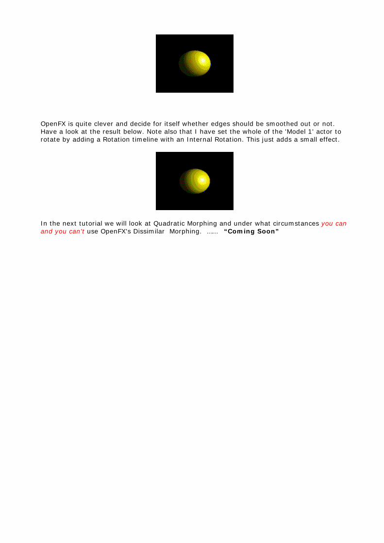
OpenFX is quite clever and decide for itself whether edges should be smoothed out or not. Have a look at the result below. Note also that I have set the whole of the 'Model 1' actor to rotate by adding a Rotation timeline with an Internal Rotation. This just adds a small effect.
In the next tutorial we will look at Quadratic Morphing and under what circumstances you can and you can't use OpenFX's Dissimilar Morphing. …… “Coming Soon”