Embed Size (px)
Citation preview
Work Theme A: Structural engineering on modern steel construction
B5 Research and development on smart robotic systems in building construction
Project Title:
a) “Adaptive Visuo-Motor Models for Robotic Welding in Uncertain Construction
Environments”
Principal Investigator: Assistant Professor David Navarro-Alarcon (ME)
Project Team: Mr.Rui Peng
Project Outline:
This project aims to pursue high-efficiency robotic arc welding, for which we propose a method
based on point cloud captured by an RGB-D camera. The method consists of two parts: welding
groove detection and 3D welding trajectory generation. The actual welding scene could be
displayed in 3D point cloud format. Focusing on the geometric feature of the welding groove, the
detection algorithm is capable of adapting well to different welding workpieces with a V-type
welding groove. Meanwhile, a 3D welding trajectory involving 6-DOF poses of the welding
groove for robotic manipulator motion is generated. With an acceptable error in trajectory
generation, the robotic manipulator can drive the welding torch to follow the trajectory and
execute welding tasks.
The major contributions of the current research work are following:
1. Establishing an integrated intelligent robotic system to automatically execute welding tasks
without too much human intervention.
2. Proposing a point cloud processing-based welding groove detection algorithm for unpredictable
workpieces.
3. Implementing an automatic 3D welding trajectory generation method on a 6-DOF robotic arm.
Scope of work:
The procedure of this project is divided into several research stages:
Stage 1 - Robot system setup
The integrated system contains a robotic manipulator (Universal Robot 3), an 3D camera (Intel
Realsense D415) and a welding torch:
(a) Universal Robot 3
The Collabrative Robot, that can interact with people and the protective guard removed, from
Universal Robots. It has a pay load of 3 kg and 6 degree of freedom. It costed HKD 160,00.
(b) 3D camera
The Intel Realsense D415 was mounted on the welding torch. It provides both RGB images and
depth images from Infra-red scanning. A ROS compatible driver was used to acquire point-clouds.
It costed RMB 1,000.
(c) Welding torch
The welding torch was physically connected to the end-effector of UR3. Currently, it is only used
as a model for cooperating with robot motion, instead of actual welding. It costed RMB 3,000.
(d) Software development platform
Ubuntu 16.04 was used as the real-time operating system. ROS (the Robot Operating System) was
employed to integrate every function module of the welding robot system. The groove detection
algorithm and the 3D welding trajectory generation method were developed in C++, while the
motion control was developed in Python. 3D Visualization of UR3 motion and simulating
environment were displayed in RViz package of ROS. Positioning, locating of the workpiece and
welding groove were done using the PCL (Point Cloud Library). The MoveIt! Package of ROS
and the Descartes package of ROS-Industrial were used to plan the movement and drive the UR3.
These software are all Open Source and can be freely downloaded from various websites.
Stage 2 - Algorithm design for welding groove detection and 3D welding trajectory generation
At this stage, an point cloud-based processing and pattern-recognition system programmed in C++
is developed for the following targets:
(a) to locate the wood workpiece which lies flat on a table and drive the robotic arm to track a
straight groove;
(b) to locate the wood workpiece which lies flat on a table and drive the robotic arm to track a
curve groove;
(c) to detect the welding groove of steel box workpieces and drive the robotic arm to track the
generated welding trajectory;
(d) to detect the welding groove of steel cylinder workpieces and drive the robotic arm to track the
generated welding trajectory.
Stage 3 - Actual welding experiment using the proposed smart robotic system
At this stage, actual welding experiment should meet following several requirements:
The improved welding groove detection algorithm could cope with general types of welding
groove, such as V-type, T-joints etc.
The 3D welding trajectory generation method could provide extra velocity control
information, especially for some particular positions like corners.
The welding machine as a part of the robot system could be triggered by software control
command.
In actual welding experiment, the system would be implemented to weld two hollow sections
together. All the process would be recorded by a special camera.
Project progress:
Sufficient research and engineering work has been done in 2019.
A comprehensive research survey of major welding robot approaches based on:
CAD
Teach-playback
2D image-processing
Mobile platforms
3D point-cloud
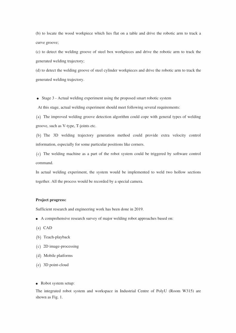
Robot system setup:
The integrated robot system and workspace in Industrial Centre of PolyU (Room W315) are
shown as Fig. 1.
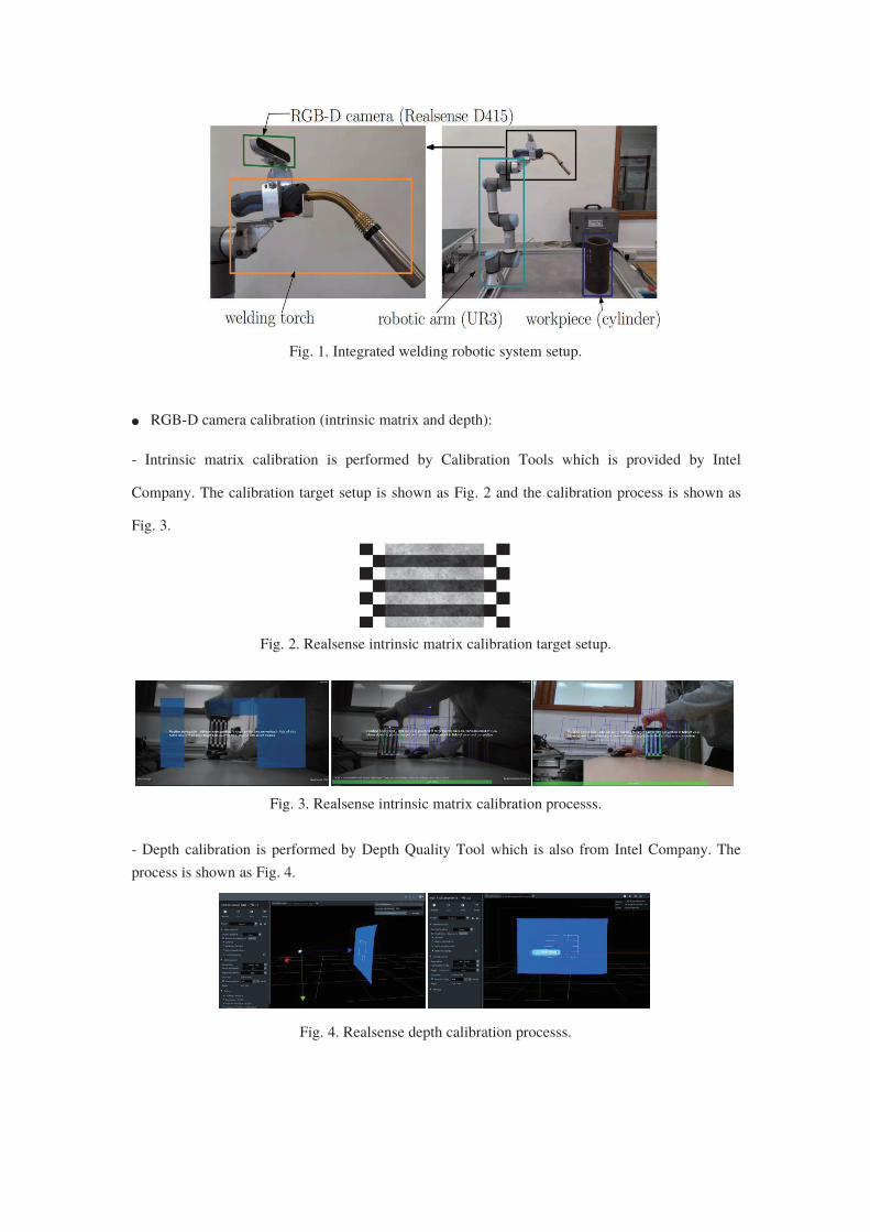
Fig. 1. Integrated welding robotic system setup.
RGB-D camera calibration (intrinsic matrix and depth):
- Intrinsic matrix calibration is performed by Calibration Tools which is provided by Intel
Company. The calibration target setup is shown as Fig. 2 and the calibration process is shown as
Fig. 3.
Fig. 2. Realsense intrinsic matrix calibration target setup.
Fig. 3. Realsense intrinsic matrix calibration processs.
- Depth calibration is performed by Depth Quality Tool which is also from Intel Company. The
process is shown as Fig. 4.
Fig. 4. Realsense depth calibration processs.
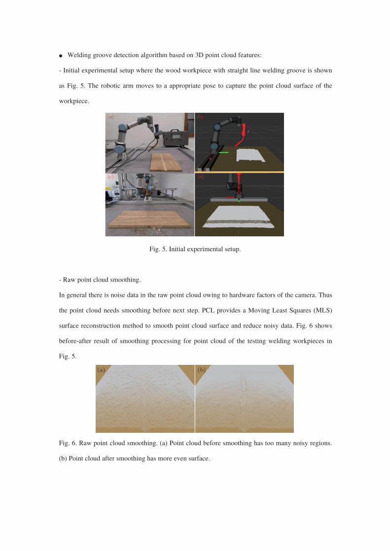
Welding groove detection algorithm based on 3D point cloud features:
- Initial experimental setup where the wood workpiece with straight line welding groove is shown
as Fig. 5. The robotic arm moves to a appropriate pose to capture the point cloud surface of the
workpiece.
Fig. 5. Initial experimental setup.
- Raw point cloud smoothing.
In general there is noise data in the raw point cloud owing to hardware factors of the camera. Thus
the point cloud needs smoothing before next step. PCL provides a Moving Least Squares (MLS)
surface reconstruction method to smooth point cloud surface and reduce noisy data. Fig. 6 shows
before-after result of smoothing processing for point cloud of the testing welding workpieces in
Fig. 5.
Fig. 6. Raw point cloud smoothing. (a) Point cloud before smoothing has too many noisy regions.
(b) Point cloud after smoothing has more even surface.
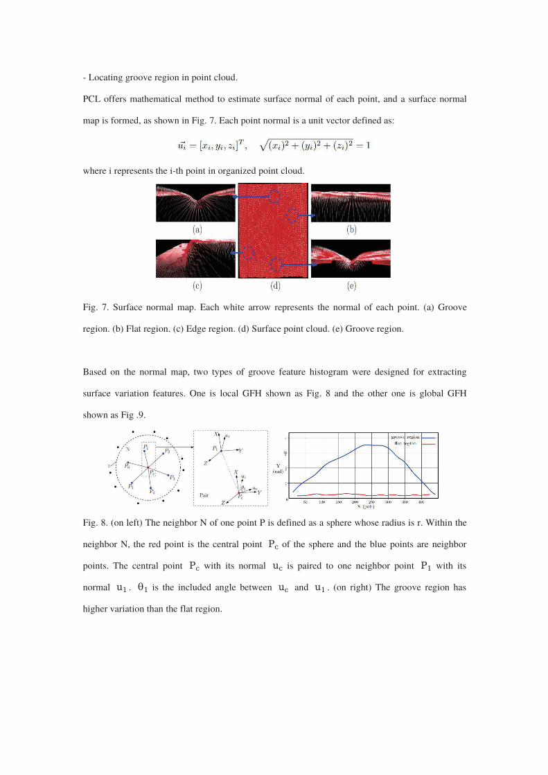
- Locating groove region in point cloud.
PCL offers mathematical method to estimate surface normal of each point, and a surface normal
map is formed, as shown in Fig. 7. Each point normal is a unit vector defined as:
where i represents the i-th point in organized point cloud.
Fig. 7. Surface normal map. Each white arrow represents the normal of each point. (a) Groove
region. (b) Flat region. (c) Edge region. (d) Surface point cloud. (e) Groove region.
Based on the normal map, two types of groove feature histogram were designed for extracting
surface variation features. One is local GFH shown as Fig. 8 and the other one is global GFH
shown as Fig .9.
Fig. 8. (on left) The neighbor N of one point P is defined as a sphere whose radius is r. Within the
neighbor N, the red point is the central point of the sphere and the blue points are neighbor
points. The central point with its normal is paired to one neighbor point with its
normal . is the included angle between and . (on right) The groove region has
higher variation than the flat region.
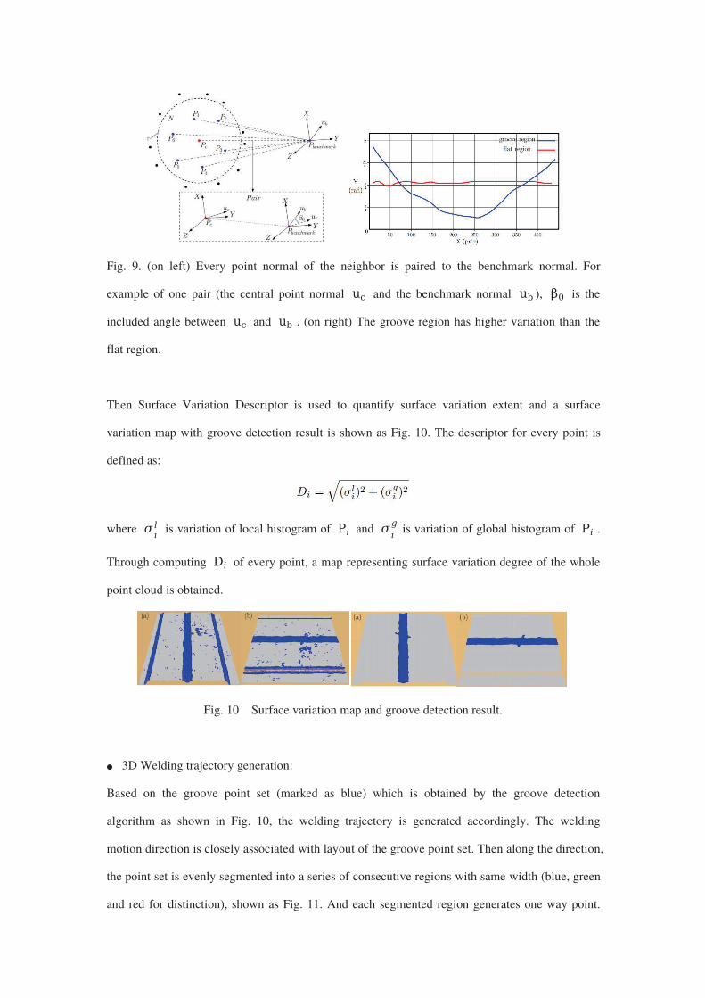
Fig. 9. (on left) Every point normal of the neighbor is paired to the benchmark normal. For
example of one pair (the central point normal and the benchmark normal ), is the
included angle between and . (on right) The groove region has higher variation than the
flat region.
Then Surface Variation Descriptor is used to quantify surface variation extent and a surface
variation map with groove detection result is shown as Fig. 10. The descriptor for every point is
defined as:
where is variation of local histogram of and is variation of global histogram of .
Through computing of every point, a map representing surface variation degree of the whole
point cloud is obtained.
Fig. 10 Surface variation map and groove detection result.
3D Welding trajectory generation:
Based on the groove point set (marked as blue) which is obtained by the groove detection
algorithm as shown in Fig. 10, the welding trajectory is generated accordingly. The welding
motion direction is closely associated with layout of the groove point set. Then along the direction,
the point set is evenly segmented into a series of consecutive regions with same width (blue, green
and red for distinction), shown as Fig. 11. And each segmented region generates one way point.
All the way points together form the final welding trajectory.
Fig. 11. 3D welding trajectory generation.
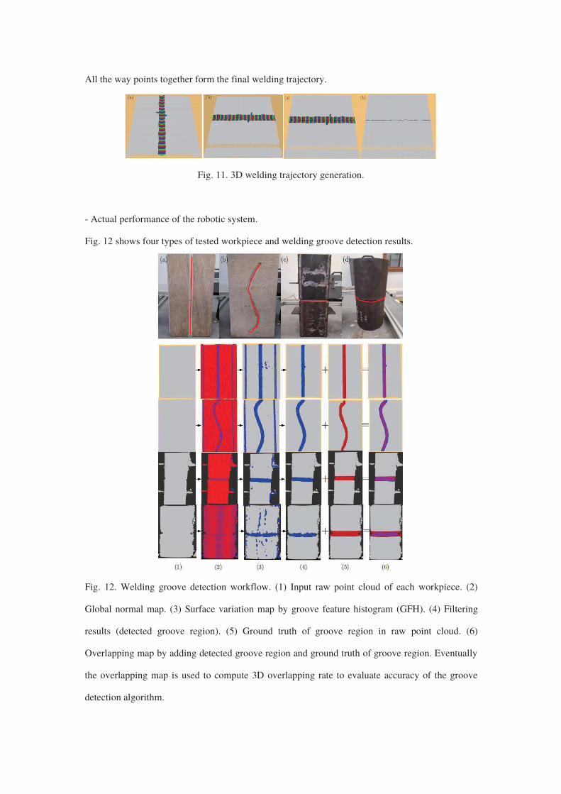
- Actual performance of the robotic system.
Fig. 12 shows four types of tested workpiece and welding groove detection results.
Fig. 12. Welding groove detection workflow. (1) Input raw point cloud of each workpiece. (2)
Global normal map. (3) Surface variation map by groove feature histogram (GFH). (4) Filtering
results (detected groove region). (5) Ground truth of groove region in raw point cloud. (6)
Overlapping map by adding detected groove region and ground truth of groove region. Eventually
the overlapping map is used to compute 3D overlapping rate to evaluate accuracy of the groove
detection algorithm.
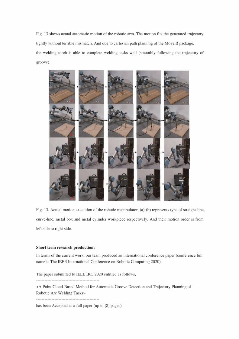
Fig. 13 shows actual automatic motion of the robotic arm. The motion fits the generated trajectory
tightly without terrible mismatch. And due to cartesian path planning of the Moveit! package,
the welding torch is able to complete welding tasks well (smoothly following the trajectory of
groove).
Fig. 13. Actual motion execution of the robotic manipulator. (a)-(b) represents type of straight-line,
curve-line, metal box and metal cylinder workpiece respectively. And their motion order is from
left side to right side.
Short term research production:
In terms of the current work, our team produced an international conference paper (conference full
name is The IEEE International Conference on Robotic Computing 2020).
The paper submitted to IEEE IRC 2020 entitled as follows,
---------------------------------------------
<A Point Cloud-Based Method for Automatic Groove Detection and Trajectory Planning of
Robotic Arc Welding Tasks>
---------------------------------------------
has been Accepted as a full paper (up to [8] pages).
Summary and future work:
So far, an integrated robot system for construction welding is established. An automatic groove
detection algorithm and 3D trajectory generation method are designed to assist the robotic arm in
efficient welding tasks. The system is composed of a robotic manipulator (Universal Robot 3), an
RGB-D camera (Realsense D415) and a welding torch. And the system has good flexibility of
facing different welding situation. The software framework is totally built up on ROS and 3D
point cloud processing is the key part. In real experiment four types of general welding
workpieces are tested. Through evaluating accuracy between welding trajectory generated by the
proposed method and the ground truth of welding groove, the motion execution performance
proves good feasibility of the designed robot system. The current problem is that the proposed
method can not cope with larger 3D point cloud of the welding workpiece surface due to more
complex geometrical region and noise. In future work, neural network instead of geometrical
feature based method may be introduced to improve robustness and accuracy of welding groove
detection algorithm. And more important work is that the improved robot system would be
implemented into actual industrial welding tasks.