Embed Size (px)
Citation preview
L
HH
II
M
DD
N
G
O
F
CQG
P
A
B
R
E
1
9
4 5 6 8
10 11
7
2 3
12
13
14
15
WORK TECRef. No. 7H144BCZZ-YYYY
SIZE S-M
16
17
89/686/CEE - Personal Protective Equipment against falls from a height.
ENITFRDEESPTSENOFIDANLCN
Full body harness for work at height.Imbracatura da lavoro anticaduta.Harnais antichute pour les travaux en hauteur.Auffanggurt für Höhenarbeite.Arnés anticaida por los trabajos en altura.Cadeirinha antiqueda para trabalhos em altura.Fallskydssele för arbete på höjd.Fallsikringssele for arbeid i høyden.Putoamisenestovaljaat korkealla tehtäville töille.Klatresele med faldsikring til arbejde i højden.Antivalgordel voor werken op hoogte.高空作业全身安全带
G= + S
C0333
IST5
2-7H
144C
T Re
v.1
07/1
5
MADE IN EUROPE EN 361:2002
AB
C
OK!
OK!
NO! NO!DANGER
OK! NO! NO! NO! OK
DANGER
MAX 30°C
H2O SOAP
MAX 5 kg
SAFE
WORKING AREA
WARNINGS
ADJUSTMENT BUCKLES
5.1
5.2
5.3
5.4
CONNECTING TO THE HARNESS
7.1 7.2
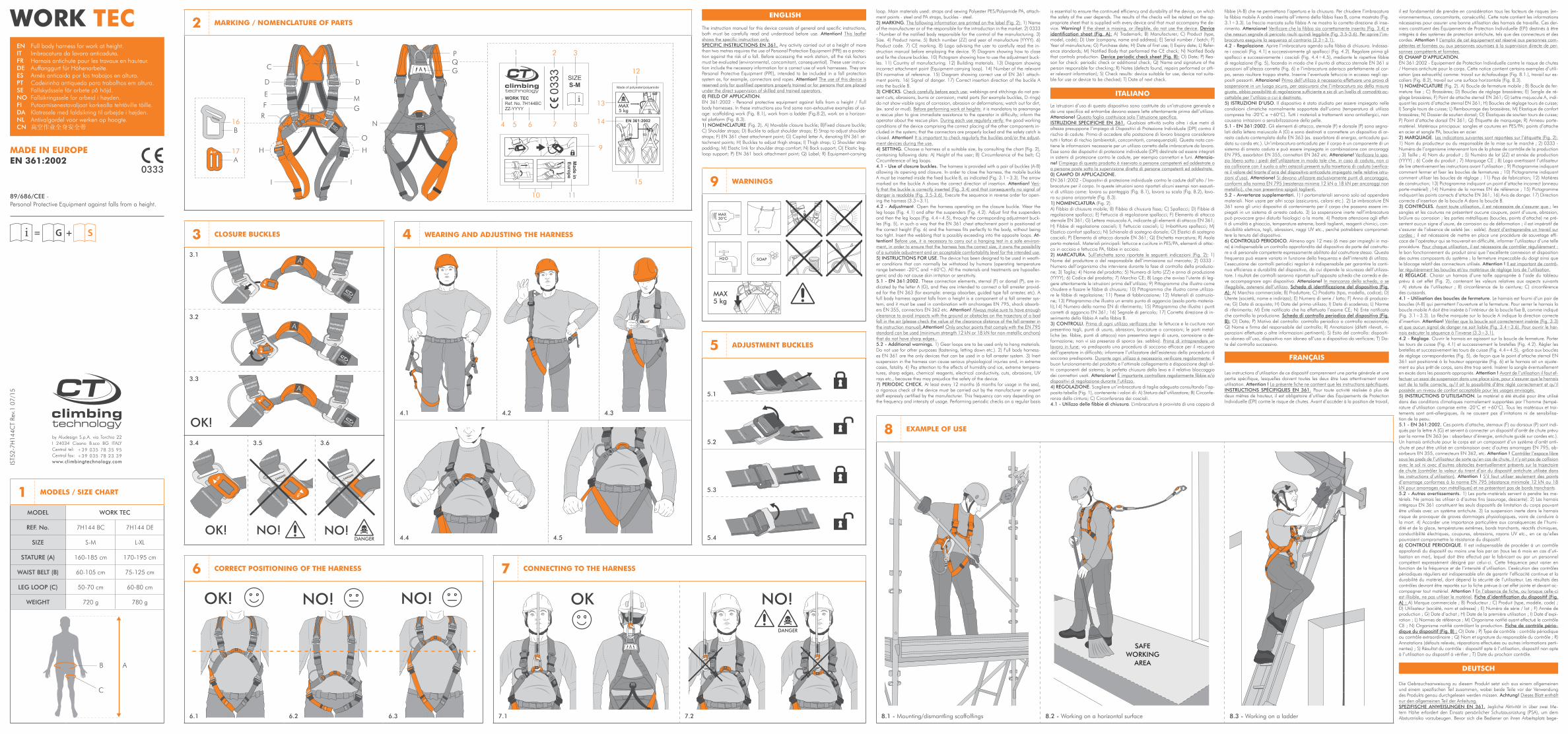
WORK TEC MARKING / NOMENCLATURE OF PARTS2
MODELS / SIZE CHART
MODEL WORK TEC
REF. No. 7H144 BC 7H144 DE
SIZE S-M L-XL
STATURE (A) 160-185 cm 170-195 cm
WAIST BELT (B) 60-105 cm 75-125 cm
LEG LOOP (C) 50-70 cm 60-80 cm
WEIGHT 720 g 780 g
1
7
9
CLOSURE BUCKLES
3.1
3.2
3.3
3.4 3.5 3.6
3 WEARING AND ADJUSTING THE HARNESS
4.1 4.2 4.3
4.4 4.5
4
CORRECT POSITIONING OF THE HARNESS
6.1 6.2 6.3
6
EXAMPLE OF USE
8.1 - Mounting/dismantling scaffolfings 8.2 - Working on a horizontal surface 8.3 - Working on a ladder
8
5
ENGLISH
The instruction manual for this device consists of general and specific instructions, both must be carefully read and understood before use. Attention! This leaflet shows the specific instruction only.SPECIFIC INSTRUCTIONS EN 361. Any activity carried out at a height of more than two metres requires the use of Personal Protection Equipment (PPE) as a protec-tion against the risk of a fall. Before accessing the work station, all the risk factors must be evaluated (environmental, concomitant, consequential). These user instruc-tion include the necessary information for a correct use of work harnesses. They are Personal Protective Equipment (PPE), intended to be included in a fall protection system as, for example, connectors and ropes. Attention! The use of this device is reserved only for qualified operators properly trained or for persons that are placed under the direct supervision of skilled and trained operators.0) FIELD OF APPLICATION.EN 361:2002 - Personal protective equipment against falls from a height / Full body harnesses. In these instructions you find some non-exhaustive examples of us-age: scaffolding work (Fig. 8.1), work from a ladder (Fig.8.2), work on a horizon-tal platform (Fig. 8.3).1) NOMENCLATURE (Fig. 2). A) Movable closure buckle; B)Fixed closure buckle; C) Shoulder straps; D) Buckle to adjust shoulder straps; E) Strap to adjust shoulder straps; F) EN 361 chest attachment point; G) Capital letter A, denoting EN 361 at-tachment points; H) Buckles to adjust thigh straps; I) Thigh strap; L) Shoulder strap padding; M) Elastic link for shoulder strap comfort; N) Back support; O) Elastic leg-loop support; P) EN 361 back attachment point; Q) Label; R) Equipment-carrying
loop. Main materials used: straps and sewing Polyester PES/Polyamide PA, attach-ment points - steel and PA straps, buckles - steel.2) MARKING. The following information are printed on the label (Fig. 2): 1) Name of the manufacturer or of the responsible for the introduction in the market. 2) 0333 - Number of the notified body responsible for the control of the manufacturing. 3) Size. 4) Product name. 5) Batch number (ZZ) and year of manufacture (YYYY). 6) Product code. 7) CE marking. 8) Logo advising the user to carefully read the in-struction manual before employing the device. 9) Diagram showing how to close and fix the closure buckles. 10) Pictogram showing how to use the adjustment buck-les. 11) Country of manufacturing. 12) Building materials. 13) Diagram showing incorrect attachment point (Equipment-carrying loop). 14) Number of the relevant EN normative of reference. 15) Diagram showing correct use of EN 361 attach-ment points. 16) Signal of danger. 17) Correct insertion direction of the buckle A into the buckle B.3) CHECKS. Check carefully before each use: webbings and stitchings do not pre-sent cuts, abrasions, burns or corrosion; metal parts (for example buckles, D-rings) do not show visible signs of corrosion, abrasion or deformations; watch out for dirt, (ex. sand or mud). Before performing work at heights: it is mandatory to prearrange a rescue plan to give immediate assistance to the operator in difficulty; inform the operator about the rescue plan. During each use regularly verify: the good working conditions of the device comprising the correct placing of the other components in-cluded in the system; that the connectors are properly locked and the safety catch is closed. Attention! It is important to check regularly the buckles and/or the adjust-ment devices during the use. 4) SETTING. Choose a harness of a suitable size, by consulting the chart (Fig. 2), containing following data: A) Height of the user; B) Circumference of the belt; C) Circumference of leg loops. 4.1 - Use of closure buckles. The harness is provided with a pair of buckles (A-B) allowing its opening and closure. In order to close the harness, the mobile buckle A must be inserted inside the fixed buckle B, as indicated (Fig. 3.1÷3.3). The arrow marked on the buckle A shows the correct direction of insertion. Attention! Veri-fy that the buckle is correctly inserted (Fig. 3.4) and that consequently no signal of danger is readable (Fig. 3.5-3.6). Execute the sequence in reverse order for open-ing the harness (3.3÷3.1).4.2 - Adjustment. Open the harness operating on the closure buckle. Wear the leg loops (Fig. 4.1) and after the suspenders (Fig. 4.2). Adjust first the suspenders and then the leg loops (Fig. 4.4÷4.5), through the corresponding adjustment buck-les (Fig. 5), in such a way that the EN 361 chest attachment point is positioned at the correct height (Fig. 6) and the harness fits perfectly to the body, without being too tight. Insert the webbing that is possibly exceeding into the apposite loops. At-tention! Before use, it is necessary to carry out a hanging test in a safe environ-ment, in order to ensure that the harness has the correct size, it owns the possibility of a suitable adjustment and an acceptable comfortability level for the intended use.5) INSTRUCTIONS FOR USE. The device has been designed to be used in weath-er conditions that can normally be withstood by humans (operating temperature range between -20°C and +60°C). All the materials and treatments are hypoaller-genic and do not cause skin irritation or sensitivity.5.1 - EN 361:2002. These connection elements, sternal (F) or dorsal (P), are in-dicated by the letter A (G), and they are intended to connect a fall arrester provid-ed for the EN 363 (for example: energy absorber, guided type fall arrester, etc). A full body harness against falls from a height is a component of a fall arrester sys-tem, and it must be used in combination with anchorages EN 795, shock absorb-ers EN 355, connectors EN 362 etc. Attention! Always make sure to have enough clearance to avoid impacts with the ground or obstacles on the trajectory of a bad fall in the air (please check the value of the clearance distance of the fall arrester in the instruction manual).Attention! Only anchor points that comply with the EN 795 standard can be used (minimum strength 12 kN or 18 kN for non-metallic anchors) that do not have sharp edges.. 5.2 - Additional warnings. 1) Gear loops are to be used only to hang materials. Do not use for other purposes (fastening, letting down etc.). 2) Full body harness-es EN 361 are the only devices that can be used in a fall arrester system. 3) Inert suspension in the harness can cause serious physiological injuries and, in extreme cases, fatality. 4) Pay attention to the effects of humidity and ice, extreme tempera-tures, sharp edges, chemical reagents, electrical conductivity, cuts, abrasions, UV rays etc., because they may prejudice the safety of the device.7) PERIODIC CHECK. At least every 12 months (6 months for usage in the sea), a rigorous check of the device must be carried out by the manufacturer or expert staff expressly certified by the manufacturer. This frequency can vary depending on the frequency and intensity of usage. Performing periodic checks on a regular basis
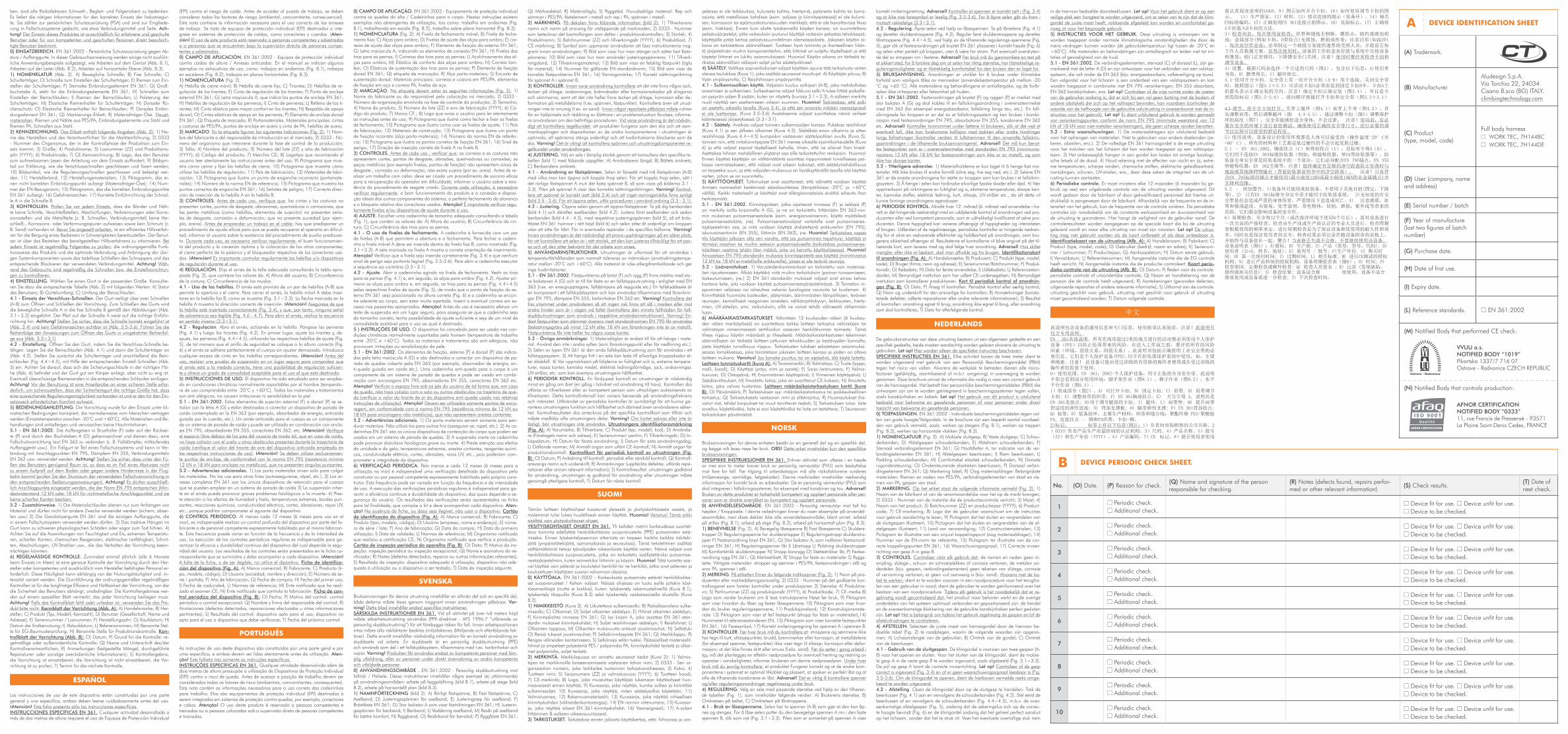
is essential to ensure the continued efficiency and durability of the device, on which the safety of the user depends. The results of the checks will be related on the ap-propriate sheet that is supplied with every device and that must accompany the de-vice. Warning! If the sheet is missing, or illegible, do not use the device. Device identification sheet (Fig. A): A) Trademark; B) Manufacturer; C) Product (type, model, code); D) User (company, name and address); E) Serial number / batch; F) Year of manufacture; G) Purchase date; H) Date of first use; I) Expiry date; L) Refer-ence standards; M) Notified Body that performed the CE check; N) Notified Body that controls production. Device periodic check sheet (Fig. B): O) Date; P) Rea-son for check: periodic check or additional check; Q) Name and signature of the person responsible for checking; R) Notes (defects found, repairs performed or oth-er relevant information); S) Check results: device suitable for use, device not suita-ble for use or device to be checked; T) Date of next check.
ITALIANO
Le istruzioni d’uso di questo dispositivo sono costituite da un’istruzione generale e da una specifica ed entrambe devono essere lette attentamente prima dell’utilizzo. Attenzione! Questo foglio costituisce solo l’istruzione specifica. ISTRUZIONI SPECIFICHE EN 361. Qualsiasi attività svolta oltre i due metri di altezza presuppone l’impiego di Dispositivi di Protezione Individuale (DPI) contro il rischio di cadute. Prima di accedere alla postazione di lavoro bisogna considerare tutti i fattori di rischio (ambientali, concomitanti, consequenziali). Questa nota con-tiene le informazioni necessarie per un utilizzo corretto delle imbracature da lavoro. Esse sono dei dispositivi di protezione individuale (DPI) destinate ad essere integrati in sistemi di protezione contro le cadute, per esempio connettori e funi. Attenzio-ne! L’impiego di questo prodotto è riservato a persone competenti ed addestrate o a persone poste sotto la supervisione diretta di persone competenti ed addestrate.0) CAMPO DI APPLICAZIONE. EN 361:2002 - Dispositivi di protezione individuale contro le cadute dall’alto / Im-bracature per il corpo. In queste istruzioni sono riportati alcuni esempi non esausti-vi di utilizzo come: lavoro su ponteggio (Fig. 8.1), lavoro su scala (Fig. 8.2), lavo-ro su piano orizzontale (Fig. 8.3).1) NOMENCLATURA (Fig. 2).A) Fibbia di chiusura mobile; B) Fibbia di chiusura fissa; C) Spallacci; D) Fibbie di regolazione spallacci; E) Fettuccia di regolazione spallacci; F) Elemento di attacco sternale EN 361; G) Lettera maiuscola A, indicante gli elementi di attacco EN 361; H) Fibbie di regolazione cosciali; I) Fettuccia cosciali; L) Imbottitura spallacci; M) Elastico comfort spallacci; N) Schienale di sostegno dorsale; O) Elastici di sostegno cosciali; P) Elemento di attacco dorsale EN 361; Q) Etichetta marcatura; R) Asola porta-materiali. Materiali principali: fettucce e cuciture in PES/PA, elementi di attac-co in acciaio e fettuccia PA, fibbie in acciaio.2) MARCATURA. Sull’etichetta sono riportate le seguenti indicazioni (Fig. 2): 1) Nome del produttore o del responsabile dell’immissione sul mercato; 2) 0333 - Numero dell’organismo che interviene durante la fase di controllo della produzio-ne; 3) Taglia; 4) Nome del prodotto; 5) Numero di lotto (ZZ) e anno di produzione (YYYY); 6) Codice del prodotto; 7) Marchio CE; 8) Logo che avvisa l’utente di leg-gere attentamente le istruzioni prima dell’utilizzo; 9) Pittogramma che illustra come chiudere e fissare le fibbie di chiusura; 10) Pittogramma che illustra come utilizza-re le fibbie di regolazione; 11) Paese di fabbricazione; 12) Materiali di costruzio-ne; 13) Pittogramma che illustra un errato punto di aggancio (asola porta-materia-li);14) Numero della norma EN di riferimento; 15) Pittogramma che illustra i punti corretti di aggancio EN 361; 16) Segnale di pericolo; 17) Corretta direzione di in-serimento della fibbia A nella fibbia B.3) CONTROLLI. Prima di ogni utilizzo verificare che: le fettucce e le cuciture non presentino tagli, punti di usura, abrasioni, bruciature o corrosioni; le parti metal-liche (es. fibbie, punti di attacco) non presentino segni di usura, corrosione o de-formazione; non vi sia presenza di sporco (es. sabbia). Prima di intraprendere un lavoro in fune: va predisposta una procedura di soccorso efficace per il recupero dell’operatore in difficoltà; informare l’utilizzatore dell’esistenza della procedura di soccorso predisposta. Durante ogni utilizzo è necessario verificare regolarmente: il buon funzionamento del prodotto e l’ottimale collegamento e disposizione degli al-tri componenti del sistema; la perfetta chiusura della leva e il relativo bloccaggio dei connettori usati. Attenzione! È importante controllare regolarmente fibbie e/o dispositivi di regolazione durante l’utilizzo.4) REGOLAZIONE. Scegliere un’imbracatura di taglia adeguata consultando l’ap-posita tabella (Fig. 1), contenente i valori di: A) Statura dell’utilizzatore; B) Circonfe-renza della cintura; C) Circonferenza dei cosciali. 4.1 - Utilizzo delle fibbie di chiusura. L’imbracatura è provvista di una coppia di
fibbie (A-B) che ne permettono l’apertura e la chiusura. Per chiudere l’imbracatura la fibbia mobile A andrà inserita all’interno della fibbia fissa B, come mostrato (Fig. 3.1÷3.3). La freccia marcata sulla fibbia A ne mostra la corretta direzione di inse-rimento. Attenzione! Verificare che la fibbia sia correttamente inserita (Fig. 3.4) e che nessun segnale di pericolo risulti quindi leggibile (Fig. 3.5-3.6). Per aprire l’im-bracatura eseguire la sequenza al contrario (3.3÷3.1).4.2 - Regolazione. Aprire l’imbracatura agendo sulla fibbia di chiusura. Indossa-re i cosciali (Fig. 4.1) e successivamente gli spallacci (Fig. 4.2). Regolare prima gli spallacci e successivamente i cosciali (Fig. 4.4÷4.5), mediante le rispettive fibbie di regolazione (Fig. 5), facendo in modo che il punto di attacco sternale EN 361 si posizioni all’altezza corretta (Fig. 6) e l’imbracatura aderisca perfettamente al cor-po, senza risultare troppo stretta. Inserire l’eventuale fettuccia in eccesso negli ap-positi passanti. Attenzione! Prima dell’utilizzo è necessario effettuare una prova di sospensione in un luogo sicuro, per assicurarsi che l’imbracatura sia della misura giusta, abbia possibilità di regolazione sufficiente e sia di un livello di comodità ac-cettabile per l’utilizzo a cui è destinata.5) ISTRUZIONI D’USO. Il dispositivo è stato studiato per essere impiegato nelle condizioni climatiche normalmente sopportate dall’uomo (temperatura di utilizzo compresa fra -20°C e +60°C). Tutti i materiali e trattamenti sono antiallergici, non causano irritazioni o sensibilizzazione della pelle.5.1 - EN 361:2002. Gli elementi di attacco, sternale (F) e dorsale (P) sono segna-lati dalla lettera maiuscola A (G) e sono destinati a connettere un dispositivo di ar-resto caduta contemplato dalla EN 363 (es. assorbitore di energia, anticaduta gui-dato su corda etc.). Un’imbracatura anticaduta per il corpo è un componente di un sistema di arresto caduta e può essere impiegata in combinazione con ancoraggi EN 795, assorbitori EN 355, connettori EN 362 etc. Attenzione! Verificare lo spa-zio libero sotto i piedi dell’utilizzatore in modo tale che, in caso di caduta, non ci sia collisione con il suolo o altri ostacoli presenti sulla traiettoria di caduta (verifica-re il valore del tirante d’aria del dispositivo anticaduta impiegato nelle relative istru-zioni d’uso). Attenzione! Si devono utilizzare esclusivamente punti di ancoraggio, conformi alla norma EN 795 (resistenza minima 12 kN o 18 kN per ancoraggi non metallici), che non presentino spigoli taglienti. 5.2 - Avvertenze supplementari. 1) I portamateriali servono solo ad appendere materiali. Non usare per altri scopi (assicurarsi, calarsi etc.). 2) Le imbracature EN 361 sono gli unici dispositivi di contenimento per il corpo che possano essere im-piegati in un sistema di arresto caduta. 3) La sospensione inerte nell’imbracatura può provocare gravi disturbi fisiologici o la morte. 4) Prestare attenzione agli effet-ti di umidità e ghiaccio, temperature estreme, bordi taglienti, reagenti chimici, con-ducibilità elettrica, tagli, abrasioni, raggi UV etc., perché potrebbero compromet-tere la tenuta del dispositivo.6) CONTROLLO PERIODICO. Almeno ogni 12 mesi (6 mesi per impieghi in ma-re) è indispensabile un controllo approfondito del dispositivo da parte del costrutto-re o di personale competente espressamente abilitato dal costruttore stesso. Questa frequenza può essere variata in funzione della frequenza e dell’intensità di utilizzo. L’esecuzione dei controlli periodici regolari è indispensabile per garantire la conti-nua efficienza e durabilità del dispositivo, da cui dipende la sicurezza dell’utilizza-tore. I risultati dei controlli saranno riportati sull’apposita scheda che correda e de-ve accompagnare ogni dispositivo. Attenzione! In mancanza della scheda, o se illeggibile, astenersi dall’utilizzo. Scheda di identificazione del dispositivo (Fig. A): A) Marchio commerciale; B) Produttore; C) Prodotto (tipo, modello, codice); D) Utente (società, nome e indirizzo); E) Numero di serie / lotto; F) Anno di produzio-ne; G) Data di acquisto; H) Data del primo utilizzo; I) Data di scadenza; L) Norme di riferimento; M) Ente notificato che ha effettuato l’esame CE; N) Ente notificato che controlla la produzione. Scheda di controllo periodico del dispositivo (Fig. B): O) Data; P) Motivo del controllo: controllo periodico o controllo eccezionale; Q) Nome e firma del responsabile del controllo; R) Annotazioni (difetti rilevati, ri-parazioni effettuate o altre informazioni pertinenti); S) Esito del controllo: dispositi-vo idoneo all’uso, dispositivo non idoneo all’uso o dispositivo da verificare; T) Da-ta del controllo successivo.
FRANÇAIS
Les instructions d’utilisation de ce dispositif comprennent une partie générale et une partie spécifique, lesquelles doivent toutes les deux être lues attentivement avant utilisation. Attention ! La présente fiche ne contient que les instructions spécifiques. INSTRUCTIONS SPÉCIFIQUES EN 361. Pour toute activité réalisée à plus de deux mètres de hauteur, il est obligatoire d’utiliser des Équipements de Protection Individuelle (EPI) contre le risque de chutes. Avant d’accéder à la position de travail,
il est fondamental de prendre en considération tous les facteurs de risques (en-vironnementaux, concomitants, consécutifs). Cette note contient les informations nécessaires pour assurer une bonne utilisation des harnais de travaille. Ces der-niers constituent des Équipements de Protection Individuelle (EPI) destinés à être intégrés à des systèmes de protection antichute, tels que des connecteurs et des cordes. Attention ! L’emploi de cet équipement est réservé aux personnes com-pétentes et formées ou aux personnes soumises à la supervision directe de per-sonnes compétents et formées. 0) CHAMP D’APPLICATION. EN 361:2002 - Equipement de Protection Individuelle contre le risque de chutes / Harnais antichute pour le corps. Cette notice contient certains exemples d’utili-sation (pas exhaustifs) comme: travail sur échafaudage (Fig. 8.1.), travail sur es-caliers (Fig. 8.2), travail sur une surface horizontale (Fig. 8.3).1) NOMENCLATURE (Fig. 2). A) Boucle de fermeture mobile ; B) Boucle de fer-meture fixe ; C) Brassières; D) Boucles de réglage brassières; E) Sangle de ré-glage brassières; F) Point de attache sternal EN 361; G) Lettre majuscule A, indi-quant les points d’attache sternal EN 361; H) Boucles de réglage tours de cuisse; I) Sangle tours de cuisse; L) Rembourrage des brassières; M) Élastique de confort brassières; N) Dossier de soutien dorsal; O) Élastiques de soutien tours de cuisse; P) Point d’attache dorsal EN 361; Q) Étiquette de marquage; R) Anneau porte-matériel. Matériaux principaux: sangles et coutures en PES/PA; points d’attache en acier et sangle PA, boucles en acier. 2) MARQUAGE. Les indications suivantes sont reportées sur l’étiquette (Fig. 2): 1) Nom du producteur ou du responsable de la mise sur le marché ; 2) 0333 - Numéro de l’organisme intervenant lors de la phase de contrôle de la production ; 3) Taille ; 4) Nom du produit ; 5) Numéro de lot (ZZ) et année de production (YYYY) ; 6) Code du produit ; 7) Marquage CE ; 8) Logo avertissant l’utilisateur de lire attentivement les instructions avant l’utilisation ; 9) Pictogramme indiquant comment fermer et fixer les boucles de fermetures ; 10) Pictogramme indiquant comment utiliser les boucles de réglage ; 11) Pays de fabrication; 12) Matières de construction; 13) Pictogramme indiquant un point d’attache incorrect (anneau porte-matériel) ;14) Numéro de la normes EN de référence ; 15) Pictogramme indiquant les points corrects d’attache EN 361; 16) Avis de danger. 17) Direction correcte d’insertion de la boucle A dans la boucle B.3) CONTRÔLES. Avant toute utilisation, il est nécessaire de s’assurer que : les sangles et les coutures ne présentent aucune coupure, point d’usure, abrasion, brûlure ou corrosion ; les parties métalliques (boucles, points d’attache) ne pré-sentent aucun signe d’usure, de corrosion ou de déformation ; il est impératif de s’assurer de l’absence de saleté (ex : sable). Avant d’entreprendre un travail sur cordes : il est nécessaire de mettre en place une procédure de sauvetage effi-cace de l’opérateur qui se trouverait en difficulté, informer l’utilisateur d’une telle procédure. Pour chaque utilisation, il est nécessaire de contrôler régulièrement : le bon fonctionnement du produit ainsi que l’excellente connexion et disposition des autres composants du système ; la fermeture impeccable du doigt ainsi que le blocage relatif des connecteurs utilisés. Attention ! Il est important de contrô-ler régulièrement les boucles et/ou matériaux de réglage lors de l’utilisation.4) RÉGLAGE. Choisir un harnais d’une taille appropriée à l’aide du tableau prévu à cet effet (Fig. 2), contenant les valeurs relatives aux aspects suivants : A) stature de l’utilisateur ; B) circonférence de la ceinture; C) circonférence des cuissards. 4.1 - Utilisation des boucles de fermeture. Le harnais est fourni d’un pair de boucles (A-B) qui permettent l’ouverture et la fermeture. Pour serrer le harnais la boucle mobile A doit être insérée à l’intérieur de la boucle fixe B, comme indiqué (Fig. 3.1÷3.3). La flèche marquée sur la boucle A indique la direction correcte d’insertion. Attention! Vérifier que la boucle soit correctement insérée (Fig. 3.3) et que aucun signal de danger ne soit lisible (Fig. 3.4÷3.6). Pour ouvrir le har-nais exécuter la séquence à l’inverse (3.3÷3.1).4.2 - Réglage. Ouvrir le harnais en agissant sur la boucle de fermeture. Porter les tours de cuisse (Fig. 4.1) et successivement le bretelles (Fig. 4.2). Régler les bretelles et successivement les tours de cuisse (Fig. 4.4÷4.5), -grâce aux boucles de réglage correspondantes (Fig. 5), de façon que le point d’attache sternal EN 361 soit positionné à la hauteur appropriée (Fig. 6) et le harnais ait un ajuste-ment au plus prêt de corps, sans être trop serré. Insérer la sangle éventuellement en excès dans les passants appropriés. Attention ! Avant de l’utilisation il faut ef-fectuer un essai de suspension dans une place sûre, pour s’assurer que le harnais soit de la taille correcte, qu’il ait la possibilité d’être réglé correctement et qu’il possède un niveau de confort acceptable pour les usages envisagés.5) INSTRUCTIONS D’UTILISATION. Le matériel a été étudié pour être utilisé dans des conditions climatiques normalement supportées par l’homme (tempé-rature d’utilisation comprise entre -20°C et +60°C). Tous les matériaux et trai-tements sont anti-allergiques, ils ne causent pas d’irritations ni de sensibilisa-tion de la peau.5.1 - EN 361:2002. Ces points d’attache, sternaux (F) ou dorsaux (P) sont indi-qués par la lettre A (G) et servent à connecter un dispositif d’arrêt de chute prévu par la norme EN 363 (ex : absorbeur d’énergie, antichute guidé sur cordes etc.). Un harnais antichute pour le corps est un composant d’un système d’arrêt anti-chute et peut être utilisé en combinaison avec d’autres amarrages EN 795, ab-sorbeurs EN 355, connecteurs EN 362, etc. Attention ! Contrôler l’espace libre sous les pieds de l’utilisateur de sorte qu’en cas de chute, il n’y ait pas de collision avec le sol ni avec d’autres obstacles éventuellement présents sur la trajectoire de chute (contrôler la valeur du tirant d’air du dispositif antichute utilisée dans les instructions d’utilisation). Attention ! S’il faut utiliser seulement des points d’amarrage conformes à la norme EN 795 (résistance minimale 12 kN ou 18 kN pour amarrages non métalliques) et ne présentant pas de bords tranchants. 5.2 - Autres avertissements. 1) Les porte-matériels servent à pendre les ma-tériels. Ne jamais les utiliser à d’autres fins (assurage, descente). 2) Les harnais intégraux EN 361 constituent les seuls dispositifs de limitation du corps pouvant être utilisés avec un système antichute. 3) La suspension inerte dans le harnais risque de provoquer de graves dommages physiologiques, voire de conduire à la mort. 4) Accorder une importance particulière aux conséquences de l’humi-dité et de la glace, températures extrêmes, bords tranchants, réactifs chimiques, conductibilité électriques, coupures, abrasions, rayons UV etc., en ce qu’elles pourraient compromettre la résistance du dispositif.6) CONTROLE PERIODIQUE. Il est indispensable de procéder à un contrôle approfondi du dispositif au moins une fois par an (tous les 6 mois en cas d’uti-lisation en mer), lequel doit être effectué par le fabricant ou par un personnel compétent expressément désigné par celui-ci. Cette fréquence peut varier en fonction de la fréquence et de l’intensité d’utilisation. L’exécution des contrôles périodiques réguliers est indispensable afin de garantir l’efficacité continue et la durabilité du matériel, dont dépend la sécurité de l’utilisateur. Les résultats des contrôles devront être reportés sur la fiche prévue à cet effet jointe et devant ac-compagner tout matériel. Attention ! En l’absence de fiche, ou lorsque celle-ci est illisible, ne pas utiliser le matériel. Fiche d’identification du dispositif (Fig. A) : A) Marque commerciale ; B) Producteur ; C) Produit (type, modèle, code) ; D) Utilisateur (société, nom et adresse) ; E) Numéro de série / lot ; F) Année de production ; G) Date d’achat ; H) Date de la première utilisation ; I) Date d’expi-ration ; L) Normes de référence ; M) Organisme notifié ayant effectué le contrôle CE ; N) Organisme notifié contrôlant la production. Fiche de contrôle pério-dique du dispositif (Fig. B) : O) Date ; P) Type de contrôle : contrôle périodique ou contrôle extraordinaire ; Q) Nom et signature du responsable du contrôle ; R) Annotations (défauts relevés, réparations effectuées ou autres informations perti-nentes) ; S) Résultat du contrôle : dispositif apte à l’utilisation, dispositif non apte à l’utilisation ou dispositif à vérifier ; T) Date du prochain contrôle.
DEUTSCH
Die Gebrauchsanweisung zu diesem Produkt setzt sich aus einem allgemeinen und einem spezifischen Teil zusammen, wobei beide Teile vor der Verwendung des Produkts genau durchgelesen werden müssen. Achtung! Dieses Blatt enthält nur den allgemeinen Teil der Anleitung.SPEZIFISCHE ANWEISUNGEN EN 361. Jegliche Aktivität in über zwei Me-tern Höhe erfordert den Einsatz persönlicher Schutzausrüstung (PSA), um dem Absturzrisiko vorzubeugen. Bevor sich die Bediener an ihren Arbeitsplatz bege-
B DEVICE PERIODIC CHECK SHEET.
No. (O) Date. (P) Reason for check.(Q) Name and signature of the person responsible for checking.
(R) Notes (defects found, repairs perfor-med or other relevant information)
(S) Check results.(T) Date of next check.
1O Periodic check.O Additional check.
O Device fit for use. O Device unfit for use.O Device to be checked.
2O Periodic check.O Additional check.
O Device fit for use. O Device unfit for use.O Device to be checked.
3O Periodic check.O Additional check.
O Device fit for use. O Device unfit for use.O Device to be checked.
4O Periodic check.O Additional check.
O Device fit for use. O Device unfit for use.O Device to be checked.
5O Periodic check.O Additional check.
O Device fit for use. O Device unfit for use.O Device to be checked.
6O Periodic check.O Additional check.
O Device fit for use. O Device unfit for use.O Device to be checked.
7O Periodic check.O Additional check.
O Device fit for use. O Device unfit for use.O Device to be checked.
8O Periodic check.O Additional check.
O Device fit for use. O Device unfit for use.O Device to be checked.
9O Periodic check.O Additional check.
O Device fit for use. O Device unfit for use.O Device to be checked.
10O Periodic check.O Additional check.
O Device fit for use. O Device unfit for use.O Device to be checked.
ben, sind alle Risikofaktoren (Umwelt-, Begleit- und Folgerisiken) zu bedenken. Es liefert die nötigen Informationen für den korrekten Einsatz der Industriegur-te. Sie zählen zur persönlichen Schutzausrüstung (PSA) und sind zur Eingliede-rung in Fallschutzsysteme gedacht, wie etwa Verbindungsmittel und Seile. Ach-tung! Der Einsatz dieses Produktes ist ausschließlich für erfahrene und geschulte Benutzer oder für von kompetenten und geschulten Personen direkt beaufsich-tigte Benutzer bestimmt.0) EINSATZBEREICH. EN 361:2002 - Persönliche Schutzausrüstung gegen Ab-sturz / Auffanggurte. In dieser Gebrauchsanweisung werden einige nicht ausführ-liche Anwendungsbeispiele aufgezeigt, wie Arbeiten auf dem Gerüst (Abb. 8.1), Arbeiten auf der Leiter (Abb. 8.2), Arbeiten auf horizontaler Ebene (Abb. 8.3).1) NOMENKLATUR (Abb. 2). A) Bewegliche Schnalle; B) Fixe Schnalle; C) Schulterträger; D) Schnalle zum Einstellen der Schulterträger; E) Riemen zum Ein-stellen der Schulterträger; F) Sternales Einbindungselement EN 361; G) Groß-buchstabe A, steht für die Einbindungselemente EN 361; H) Schnallen zum Einstellen der Beinschlaufen; I) Riemen der Beinschlaufen; L) Polsterung der Schulterträger; M) Elastische Riemenhalter für Schulterträger; N) Dorsaler Rü-ckenschutz; O) Elastische Riemenhalter für Beinschlaufen; P) Dorsales Einbin-dungselement EN 361; Q) Markierungs-Etikett; R) Materialträger-Öse. Haupt-materialien: Riemen und Nähte aus PES/PA, Einbindungselemente uns Stahl und Riemen PA, Schnallen aus Stahl.2) KENNZEICHNUNG. Das Etikett enthält folgende Angaben (Abb. 2): 1) Na-me des Herstellers und des Verantwortlichen für die Markteinführung; 2) 0333 - Nummer des Organismus, der in der Kontrollphase der Produktion zum Ein-satz kommt; 3) Größe; 4) Produktname; 5) Losnummer (ZZ) und Produktions-jahr (YYYY); 6) Produktcode; 7) CE-Kennzeichnung; 8) Logo, das den Benutzer zum aufmerksamen Lesen der Anleitung vor dem Einsatz auffordert; 9) Bildsym-bol zur Erklärung, wie die Verschlussschnallen geschlossen und fixiert werden; 10) Bildsymbol, wie die Regulierungsschnallen geschlossen und befestigt wer-den. 11) Herstellerland; 12) Herstellungsmaterialien; 13) Piktogramm, das ei-nen nicht korrekten Einbindungspunkt aufzeigt (Materialträger-Öse); 14) Num-mer der EN-Bezugsnorm; 15) Piktogramm, das die korrekten Einbindungspunkte EN 361 aufzeigt; 16) Gefahrenzeichen. 17) Korrekte Einführrichtung der Schnal-le A in die Schnalle B. 3) KONTROLLEN. Prüfen Sie vor jedem Einsatz, dass die Bänder und Näh-te keine Schnitte, Verschleißstellen, Abschürfungen, Verbrennungen oder Korro-sionsstellen und die Metallteile (z. B. Schnallen, Verbindungsmittel) keine Ver-schleiß-, Korrosions- oder Verformungsspuren aufweisen sowie kein Schmutz (z. B. Sand) vorhanden ist. Bevor Sie angeseilt arbeiten, ist ein effizientes Hilfsverfah-ren für die Bergung eines Bedieners in Schwierigkeiten bereitzustellen. Der Benut-zer ist über das Bestehen des bereitgestellten Hilfsverfahrens zu informieren. Bei jedem Einsatz ist regelmäßig Folgendes zu prüfen: die ordnungsgemäße Funk-tionsweise des Produkts und die optimale Verbindung und Anbringung der übri-gen Systemkomponenten sowie das tadellose Schließen des Schnappers und das entsprechende Blockieren der verwendeten Verbindungsmittel. Achtung! Wäh-rend des Gebrauchs sind regelmäßig die Schnallen bzw. die Einstellvorrichtun-gen zu kontrollieren.4) EINSTELLUNG. Wählen Sie einen Gurt in der passenden Größe. Konsultie-ren Sie dazu die entsprechende Tabelle (Abb. 2) mit folgenden Werten: A) Statur des Benutzers; B) Gürtelumfang; C) Umfang der Beinschlaufen. 4.1 - Einsatz der Verschluss-Schnallen. Der Gurt verfügt über zwei Schnallen (A-B) zum Öffnen und Schließen der Vorrichtung. Zum Schließen des Gurts wird die bewegliche Schnalle A in die fixe Schnalle B gemäß den Abbildungen (Abb. 3.1÷3.3) eingeführt. Der Pfeil auf der Schnalle A weist auf die richtige Einführ-richtung hin. Achtung! Stellen Sie sicher, dass die Schnalle korrekt eingeführt ist (Abb. 3.4) und kein Gefahrenzeichen sichtbar ist (Abb. 3.5-3.6). Führen Sie die Reihenfolge der Anweisungen zum Öffnen des Gurts in umgekehrter Reihenfol-ge aus (Abb. 3.3÷3.1)4.2 - Einstellung. Öffnen Sie den Gurt, indem Sie die Verschluss-Schnalle be-tätigen. Legen Sie die Beinschlaufen (Abb. 4.1) und dann die Schulterträger an (Abb. 4.2). Stellen Sie zunächst die Schulterträger und anschließend die Bein-schlaufen (Fig. 4.4÷4.5), mit Hilfe der entsprechenden Einstell-Schnallen (Abb. 5) ein. Achten Sie darauf, dass sich die Sicherungsschlaufe in der richtigen Hö-he (Abb. 6) befindet und der Gurt gut am Körper anliegt, aber nicht zu eng ist. Eventuell überschüssige Riemenenden in die entsprechenden Schlaufen einfügen. Achtung! Vor der Benutzung ist eine Anseilprobe an einer sicheren Stelle erfor-derlich, um sicherzustellen, dass der Sicherheitsgurt die richtige Größe hat, dass eine ausreichende Regulierungsmöglichkeit vorhanden ist und er den für den Ein-satzzweck erforderlichen Komfort aufweist.5) BEDIENUNGSANLEITUNG. Die Vorrichtung wurde für den Einsatz unter kli-matischen Bedingungen konzipiert, die normalerweise vom Menschen vertragen werden (Einsatztemperatur zwischen -20°C und +60°C). Alle Materialien und Be-handlungen sind antiallergen und verursachen keine Hautirritationen.5.1 - EN 361:2002. Die Auffangösen in Brusthöhe (F) oder auf der Rücksei-te (P) sind durch den Buchstaben A (G) gekennzeichnet und dienen dazu, eine Fallschutzvorrichtung laut EN 363 zu verbinden (z. B. Falldämpfer, mitlaufendes Auffanggerät usw.). Ein Fallgurt ist Teil eines Fallschutzsystems und kann in Ver-bindung mit Anschlagpunkten EN 795, Dämpfern EN 355, Verbindungsmitteln EN 362 usw. verwendet werden. Achtung! Stellen Sie sicher, dass unter den Fü-ßen des Benutzers genügend Raum ist, so dass es im Fall eines Absturzes nicht zu einem Aufprall auf dem Boden oder gegen andere Hindernisse in der Flug-bahn kommt (prüfen Sie den Sturzraum der verwendeten Fallschutzvorrichtung in den entsprechenden Bedienungsanweisungen). Achtung! Es dürfen ausschließ-lich Anschlagpunkte eingesetzt werden, die der Norm EN 795 entsprechen (Min-destwiderstand 12 kN oder 18 kN für nichtmetallische Anschlagpunkte) und sie keine scharfen Kanten besitzen. 5.2 - Zusatzhinweise. 1) Die Materialschlaufen dienen nur zum Anhängen von Material und dürfen nicht für andere Zwecke verwendet werden (sichern, absei-len usw.) 2) Die Ganzkörpergurte EN 361 sind die einzigen Auffanggurte, die in einem Fallschutzsystem verwendet werden dürfen. 3) Das inaktive Hängen im Gurt kann zu schweren physiologischen Schäden oder sogar zum Tod führen. 4) Achten Sie auf die Auswirkungen von Feuchtigkeit und Eis, extremen Temperatu-ren, scharfen Kanten, chemischen Reagenzien, elektrischer Leitfähigkeit, Schnit-ten, Abschürfungen, UV-Strahlen usw., die das Verhalten der Vorrichtung beein-trächtigen könnten.6) REGELMÄSSIGE KONTROLLE. Zumindest einmal jährlich (alle 6 Monate beim Einsatz im Meer) ist eine genaue Kontrolle der Vorrichtung durch den Her-steller oder kompetentes und ausdrücklich vom Hersteller befähigtes Personal er-forderlich. Diese Häufigkeit kann abhängig von der Nutzungshäufigkeit und -in-tensität variiert werden. Die Durchführung der ordnungsgemäßen regelmäßigen Kontrollen ist für die langfristige Effizienz und Haltbarkeit der Vorrichtung, von der die Sicherheit des Benutzers abhängt, unabdingbar. Die Kontrollergebnisse wer-den auf einem speziellen Blatt vermerkt, das jeder Vorrichtung beiliegen muss. Achtung! Falls das Kontrollblatt fehlt oder unlesbar ist, verwenden Sie das Pro-dukt bitte nicht. Kennblatt der Vorrichtung (Abb. A): A) Handelsmarke; B) Her-steller; C) Produkt (Typ, Modell, Kennzahl); D) Benutzer (Gesellschaft, Name und Adresse); E) Seriennummer / Losnummer; F) Herstellungsjahr; G) Kaufdatum; H) Datum der Erstbenutzung; I) Ablaufdatum; L) Referenznormen; M) Benannte Stel-le für EG-Baumusterprüfung; N) Benannte Stelle für Produktionskontrolle. Kon-trollblatt der Vorrichtung (Abb. B): O) Datum; P) Grund für die Kontrolle: re-gelmäßige oder außerordentliche Kontrolle; Q) Name und Unterschrift des/der Kontrollverantwortlichen; R) Anmerkungen (festgestellte Mängel, durchgeführte Reparaturen oder sonstige zweckdienliche Informationen); S) Kontrollergebnis: die Vorrichtung ist einsatzbereit, die Vorrichtung ist nicht einsatzbereit, die Vor-richtung ist zu prüfen; T) Termin für die nächste Kontrolle.
ESPAÑOL
Las instrucciones de uso de este dispositivo están constituidas por una parte general y una específica, ambas deben leerse cuidadosamente antes del uso. ¡Atención! Este folio presenta sólo las instrucciones específicas. INSTRUCCIONES ESPECÍFICAS EN 361. Cualquier actividad desarrollada a más de dos metros de altura requiere el uso de Equipos de Protección Individual
(EPI) contra el riesgo de caída. Antes de acceder al puesto de trabajo, se deben considerar todos los factores de riesgo (ambiental, concomitante, consecuencial). Esta nota contiene la información necesaria para el uso correcto de los arneses de trabajo. Se trata de equipos de protección individual (EPI) destinados a inte-grase en sistemas de protección de caídas, como conectores y cuerdas. ¡Aten-ción! El uso de este producto está reservado a personas competentes y adiestradas o a personas que se encuentren bajo la supervisión directa de personas compe-tentes y adiestradas.0) CAMPO DE APLICACIÓN. EN 361:2002 - Equipos de protección individual contra caídas de altura / Arneses anticaídas. En el manual se indican algunos ejemplos no exhaustivos de uso, como: trabajos en andamios (Fig. 8.1), trabajos en escaleras (Fig. 8.2), trabajos en planos horizontales (Fig. 8.3). 1) NOMENCLATURA (Fig. 2).A) Hebilla de cierre móvil; B) Hebilla de cierre fija; C) Tirantes; D) Hebillas de re-gulación de los tirantes; E) Cinta de regulación de los tirantes; F) Punto de anclaje esternal EN 361; G) Letra mayúscula A, que indica los puntos de anclaje EN 361; H) Hebillas de regulación de las perneras; I) Cinta de perneras; L) Relleno de los ti-rantes; M) Cinta elástica para mayor confort en los tirantes; N) Respaldo de apoyo dorsal; O) Cintas elásticas de apoyo en las perneras; P) Elemento de anclaje dorsal EN 361; Q) Etiqueta de marcado; R) Portamateriales. Materiales principales: cintas y costuras de PES/PA, puntos de anclaje en acero y cinta de PA, hebillas de acero.2) MARCADO. En la etiqueta figuran las siguientes indicaciones (Fig. 2): 1) Nom-bre del fabricante o del responsable de introducción en el mercado; 2) 0333 - Nú-mero del organismo que interviene durante la fase de control de la producción; 3) Talla; 4) Nombre del producto; 5) Número del lote (ZZ) y año de fabricación (YYYY); 6) Código del producto; 7) Marchio CE; 8) Logotipo que recomienda al usuario leer atentamente las instrucciones antes del uso; 9) Pictograma que mue-stra cómo cerrar y fijar las hebillas de cierre; 10) Pictograma que muestra cómo utilizar las hebillas de regulación; 11) País de fabricación; 12) Materiales de fabri-cación; 13) Pictograma que ilustra un punto de enganche incorrecto (portamate-riales); 14) Número de la norma EN de referencia; 15) Pictograma que muestra los puntos correctos de enganche EN 361; 16) Señales de peligro; 17) Correcta direc-ción de inserción de la hebilla A en la hebilla B.3) CONTROLES. Antes de cada uso, verifique que: las cintas y las costuras no presenten cortes, puntos de desgaste, abrasiones, quemaduras o corrosiones; que las partes metálicas (como hebillas, elementos de sujeción) no presenten seña-les de desgaste, corrosión o deformación; que no presente suciedad (por ejem-plo, arena). Antes de emprender un trabajo en el cable: hay que predisponer un procedimiento de ayuda eficaz para que se pueda recuperar el operario en dificul-tad; informar al usuario sobre la existencia del procedimiento de auxilio predisues-to. Durante cada uso, es necesario verificar regularmente: el buen funcionamien-to del producto y la conexión óptima y la colocación de los otros componentes; el cierre perfecto de la palanca y el bloqueador respectivo de los conectores usa-dos. ¡Atención! Es importante controlar regularmente las hebillas y/o dispositivos de regulación durante el uso.4) REGULACIÓN. Elija el arnés de la talla adecuada consultando la tabla apro-piada (Fig. 2), que contiene los valores de: A) Altura del usuario; B) Circunferencia de la cintura; C) Circunferencia de los muslos. 4.1 - Uso de las hebillas. El arnés está provisto de un par de hebillas (A-B) que permite la apertura y el cierre. Para cerrar el arnés, la hebilla móvil A debe inser-tarse en la hebilla fija B, como se muestra (Fig. 3.1÷3.3). La flecha marcada en la hebilla A muestra la dirección correcta de inserción. ¡Atención! Asegúrese de que la hebilla esté insertada correctamente (Fig. 3.4), y que, por tanto, ninguna señal de advertencia sea legible (Fig. 4.6 - 4.7). Para abrir el arnés, realice la secuencia en sentido inverso (3.3÷3.1).4.2 - Regulación. Abra el arnés, actúando en la hebilla. Póngase las perneras (Fig. 4.1) y luego los tirantes (Fig. 4.2). En primer lugar, ajuste los tirantes y, de-spués, las perneras (Fig. 4.4÷4.5), utilizando las respectivas hebillas de ajuste (Fig. 5), de tal manera que el anillo de seguridad se coloque a la altura correcta (Fig. 6) y el arnés se adhiera perfectamente al cuerpo sin ajustar demasiado. Introduzca cualquier exceso de cinta en las trabillas correspondientes. ¡Atención! Antes del uso, realizar una prueba de suspensión en un lugar seguro para comprobar que el arnés está a la medida correcta, tiene una posibilidad de regulación suficien-te y ofrece un grado de comodidad aceptable para el uso al que está destinado.5) INSTRUCCIONES DE USO. El dispositivo ha sido estudiado para ser emplea-do en condiciones climáticas normalmente soportables por el hombre (temperatu-ra de uso comprendida entre -20°C y +60°C). Todos los materiales y tratamientos son anti alérgicos, no causan irritaciones ni sensibilidad en la piel. 5.1 - EN 361:2002. Estos elementos de sujeción esternal (F) o dorsal (P) se se-ñalan con la letra A (G) y están destinados a conectar un dispositivo de parada de caída contemplado en la EN 363 (por ejemplo, absorbedor de energía, anticaída guiada por la cuerda, etc.). Un arnés anticaída para el cuerpo es un componente de un sistema de parada de caída y puede ser utilizado en combinación con ancla-jes EN 795, absorbedores EN 355, conectores EN 362, etc. ¡Atención! Verifique el espacio libre debajo de los pies del usuario de modo tal, que en caso de caída, no haya colisión con el suelo u otros obstáculos presentes durante la trayectoria de caída (verifique el valor del tirante de aire del dispositivo anticaída empleado en las respectivas instrucciones de uso). ¡Atención! Se deben utilizar exclusivamen-te puntos de anclaje, de conformidad con la norma EN 795 (resistencia mínima 12 kN o 18 kN para anclajes no metálicos), que no presenten ángulos punzantes.5.2 - Advertencias adicionales. 1) Los porta materiales sirven solo para colgar los materiales. No los use para otros fines (autoasegurarse, rápel, etc.). 2) Los ar-neses completos EN 361 son los únicos dispositivos de retención para el cuerpo que se pueden emplear en un sistema de parada de caída 3) La suspensión inher-te en el arnés puede provocar graves problemas fisiológicos o la muerte. 4) Pres-te atención a los efectos de humedad y hielo, temperaturas extremas, bordes pun-zantes, reacciones químicas, conductividad eléctrica, cortes, abrasiones, rayos UV, etc., porque podrían comprometer el aguante del dispositivo.6) CONTROL PERIÓDICO. Al menos cada 12 meses (6 meses para uso en el mar), es indispensable realizar un control profundo del dispositivo por parte del fa-bricante o de personal competente expresamente habilitado por el mismo fabrican-te. Esta frecuencia puede variar en función de la frecuencia y de la intensidad de uso. La ejecución de los controles periódicos regulares es indispensable para ga-rantizar la eficacia y durabilidad continua del dispositivo del cual depende la segu-ridad del usuario. Los resultados de los controles serán presentados en la ficha co-rrespondiente que se suministra y debe acompañar a cada dispositivo. ¡Atención! A falta de la ficha, o de ser ilegible, no utilice el dipositivo. Ficha de identifica-ción del dispositivo (Fig. A): A) Marca comercial; B) Fabricante; C) Producto (ti-po, modelo, código); D) Usuario (sociedad, nombre y dirección); E) Número de se-rie / partida; F) Año de fabricación; G) Fecha de compra; H) Fecha del primer uso; I) Fecha de caducidad; L) Normas de referencia; M) Ente notificado que ha reali-zado el examen CE; N) Ente notificado que controla la fabricación. Ficha de con-trol periódico del dispositivo (Fig. B): O) Fecha; P) Motivo del control: control periódico o control excepcional; Q) Nombre y firma del responsable del control; R) Anotaciones (defectos detectados, reparaciones efectuadas u otras informaciones pertinentes); S) Resultado del control: dispositivo apto para el uso, dispositivo no apto para el uso o dispositivo que debe verificarse; T) Fecha del próximo control.
PORTUGUÊS
As instruções de uso deste dispositivo são constituídas por uma parte geral e por uma específica, e ambas devem ser lidas atentamente antes da utilização. Aten-ção! Este folheto traz somente as instruções específicas.INSTRUÇÕES ESPECÍFICAS EN 361. Qualquer atividade desenvolvida além de dois metros de altura pressupõe a utilização de Dispositivos de Proteção Individual (DPI) contra o risco de queda. Antes de acessar a posição de trabalho devem ser considerados todos os fatores de risco (ambientais, concomitantes, consequentes).Esta nota contém as informações necessárias para o uso correto das cadeirinhas para trabalho. Elas são equipamentos de proteção individual (EPI) destinados a serem integrados em sistemas de proteção contra quedas, por exemplo, conectores e cabos. Atenção! O uso deste produto é reservado a pessoas competentes e treinadas ou a pessoas colocadas sob a supervisão direta de pessoas competentes e trainadas.
0) CAMPO DE APLICAÇÃO. EN 361:2002 - Equipamento de proteção individual contra as quedas do alto / Cadeirinhas para o corpo. Nestas instruções existem exemplos não abrangentes de utilização, tais como: trabalho em andaimes (Fig. 8.1), trabalhando em escala (Fig. 8.2), trabalho sobre plano horizontal (Fig. 8.3).1) NOMENCLATURA (Fig. 2). A) Fivela de fechamento móvel; B) Fivela de fecha-mento fixa; C) Alças para ombro; D) Fivelas de ajuste das alças para ombro; E) cor-reias de ajuste das alças para ombro; F) Elemento de fixação do esterno EN 361; G) Letra maiúscula A, indicando os elementos de conexão EN 361; H) Fivelas das tiras para as pernas; I) Correias das tiras para as pernas; L) Acolchoamento das al-ças para ombro; M) Elástico de conforto das alças para ombro; N) Correia lom-bar; O) Elásticos de sustentação das tiras para as pernas; P) Elemento de fixação dorsal EN 361; Q) etiqueta de marcação; R) Alça porta-materiais; S) Encosto de sustentação dorsal. Materiais principais: correias e costura em PES/PA, elementos de fixação em aço e correia PA, fivelas de aço.2) MARCAÇÃO. Na etiqueta devem estar as seguintes informações (Fig. 2): 1) Nome do fabricante ou do responsável pela colocação no mercado; 2) 0333 - Número da organização envolvida na fase de controle da produção; 3) Tamanho; 4) Nome do produto; 5) Número do lote (ZZ) e ano de fabricação (YYYY); 6) Có-digo do produto; 7) Marca CE ; 8) Logo que avisa o usuário para ler atentamente as instruções antes do uso; 9) Pictograma que ilustra como fechar e fixar as fivelas de fechamento; 10) Pictograma que ilustra como usar as fivelas de ajuste; 11) País de fabricação; 12) Materiais de construção; 13) Pictograma que ilustra um ponto de fixação incorreto (alça porta-materiais); 14) Número da norma EN de referên-cia; 15) Pictograma que ilustra os pontos corretos de fixação EN 361; 16) Sinal de perigo; 17) Direção de inserção correta da fivela A na fivela B.3) CONTROLES. Antes de cada uso , verificar que: as correias e as costuras não apresentem cortes, pontos de desgaste, abrasões, queimaduras ou corrosões; as peças metálicas (por exemplo fivelas, pontos de fixação) não apresentem sinais de desgaste , corrosão ou deformação; não exista sujeira (por ex. areia). Antes de re-alizar um trabalho com cabo: deve ser criado um procedimento de socorro eficaz para a recuperação do operador em dificuldade; informar o usuário sobre a exis-tência do procedimento de resgate criado. Durante cada utilização, é necessário verificar regularmente: o bom funcionamento do produto e a conexão e disposi-ção ideais dos outros componentes do sistema; o perfeito fechamento da alavanca e o bloqueio relativo dos conectores usados. Atenção! É importante verificar regu-larmente fivelas e/ou dispositivos de ajuste durante o uso.4) AJUSTE. Escolher uma cadeirinha de tamanho adequado consultando a tabela (Fig. 1), que contém os valores de: A) Altura do usuário; B) Circunferência da cin-tura; C) Circunferência das tiras para as pernas.4.1 - O uso de fivelas de fechamento. A cadeirinha é fornecida com um par de fivelas (A-B) que permitem a abertura e o fechamento. Para fechar a cadeiri-nha a fivela móvel A deve ser inserida dentro da fivela fixa B, como mostrado (Fig. 3.1÷3.3). A seta marcada na fivela A mostra a correta orientação de inserimento. Atenção! Verificar que a fivela seja inserida corretamente (Fig. 3.4) e que nenhum sinal de perigo seja portanto legível (Fig. 3.5-3.6). Para abrir a cadeirinha executar a sequência ao contrário (3.3÷3.1).4.2 - Ajuste. Abrir a caderirinha agindo na fivela de fechamento. Vestir as tiras para as pernas (Fig. 4.1) e, em seguida, as alças para ombro (Fig. 4.2). Ajustar pri-meiro as alças para ombro e, em seguida, as tiras para as pernas (Fig. 4.4÷4.5) pelas respectivas fivelas de ajuste (Fig. 5), de modo que o ponto de fixação do es-terno EN 361 seja posicionado na altura correta (Fig. 6) e a cadeirinha se encon-tre aderente ao corpo, sem estar muito apertada. Inserir a eventual correia em ex-cesso nos passantes apropriados. Atenção! Antes do uso é necessário efetuar um teste de suspensão em um lugar seguro, para assegurar-se que a cadeirinha seja do tamanho correto, tenha possibilidade de ajuste suficiente e seja de um nível de comodidade aceitável para o uso ao qual é destinado.5 ) INSTRUÇÕES DE USO. O dispositivo foi concebido para ser usado nas con-dições climáticas normalmente suportadas pelo homem (temperatura de trabalho entre -20°C e +60°C). Todos os materiais e tratamentos são anti-alérgicos, não provocam irritações ou sensibilização da pele.5.1 - EN 361:2002. Os elementos de fixação, esterno (F) e dorsal (P) são indica-dos pela letra maiúscula A (G) e são destinados a conectar um dispositivo de pa-rada de quedas coberto pela EN 363 (por exemplo, absorvedor de energia, an-ti-queda guiado em corda etc.). Uma cadeirinha anti-queda para o corpo é um componente de um sistema de parada de quedas e pode ser usado em combi-nação com ancoragens EN 795, absorvedores EN 355, conectores EN 362 etc. Atenção! Verificar o espaço livre sob os pés do usuário de tal forma que, em caso de queda, não haja colisão com o solo ou outros obstáculos na trajetória de que-da (verificar o valor do tirante de ar do dispositivo anti-queda usado nas relativas instruções de utilização). Atenção! Devem ser utilizados somente pontos de anco-ragem, em corformidade com a norma EN 795 (resistência mínima de 12 kN ou 18 kN para ancoragens não-metálicas), que não apresentem arestas cortantes.5.2 - Advertências adicionais. 1) Os porta-materiais servem somente para pen-durar materiais. Não utilizá-los para outros fins (assegurar-se, rapel, etc.). 2) As ca-deirinhas EN 361 são os únicos dispositivos de contenção do corpo que podem ser usados em um sistema de parada de quedas. 3) A suspensão inerte na cadeirinha pode provocar distúrbios fisiológicos grave ou morte. 4) Preste atenção aos efeitos da umidade e do gelo, temperaturas extremas, arestas cortantes, reagentes quími-cos, condutividade elétrica, cortes, abrasões, raios UV, etc., pois poderiam com-prometer a integridade do dispositivo.6) VERIFICAÇÃO PERIÓDICA. Pelo menos a cada 12 meses (6 meses para a utilização no mar) é indispensável uma verificação detalhada do dispositivo pelo construtor ou por pessoal competente expressamente habilitado pelo próprio cons-trutor. Esta frequência pode ser variada em função da frequência e da intensidade de uso. A execução das verificações periódicas regulares é indispensável para ga-rantir a eficiência contínua e durabilidade do dispositivo, das quais depende a se-gurança do usuário. Os resultados das verificações serão apresentados na ficha para tal finalidade, que compõe o kit e deve acompanhar cada dispositivo. Aten-ção! Na ausência da ficha, ou daso seja ilegível, não usar o dispositivo. Cartão de identificação do dispositivo (Fig. A): A) Marca comercial; B) Fabricante; C) Produto (tipo, modelo, código); D) Usuário (empresa, nome e endereço); E) núme-ro de série / lote; F) Ano de fabricação; G) Data da compra; H) Data da primeira utilização; I) Data de validade; L) Normas de referência; M) Organismo notificado que realizou a certificação CE; N) Organismo notificado que verifica a produção. Cartão de inspeção periódica do aparelho (Fig. B): O) Data; P) Motivo da ins-peção: inspeção periódica ou inspeção excepcional; Q) Nome e assinatura do ve-rificador; R) Notas (defeitos detectados, reparos ou outras informações relevantes); S) Resultado da inspeção: dispositivo adequado à utilização, dispositivo não ade-quado à utilização ou o dispositivo a ser testado; T) Data da inspeção seguinte.
SVENSKA
Bruksanvisningen för denna utrustning innehåller en allmän del och en specifik del, båda delarna måste läsas igenom noggrant innan användningen påbörjas. Var-ning! Detta blad innehåller endast specifika instruktioner. SÄRSKILDA INSTRUKTIONER EN 361. Vid all aktivitet på över två meters höjd måste säkerhetsutrustning användas (PPE-direktivet - AFS 1996:7 ”utförande av personlig skyddsutrustning”) för att förebygga risken för fall. Innan arbetspositionen intas måste alla riskfaktorer beaktas (miljöfaktorer, åtföljande och efterföljande fak-torer). Detta avsnitt innehåller nödvändig information för en korrekt användning av skyddssele vid arbete. En skyddssele är en personlig skyddsutrustning (PPE)och används som del i ett fallskyddssystem, tillsammans med t.ex. karbinhakar och vajrar. Varning! Produkten får användas endast av kompetenta personer med läm-plig utbildning, eller av personer under direkt övervakning av andra kompetenta och utbildade personer.0) ANVÄNDNINGSOMRÅDE . EN 361:2002 - Personlig skyddsutrustning mot fallrisk / Helsele. Dessa instruktioner innehåller några exempel (ej uttömmande) på användningsområden: arbete på byggställning (bild 8.1), arbete på stege (bild 8.2), arbete på horisontellt plan (bild 8.3).1) NAMNFÖRTECKNING (bild 2). A) Rörligt fästspänne; B) Fast fästspänne; C) Axelband; D) Justeringsspännen för axelband; E) Justeringsrep för axelband; F) Bröstfäste EN 361; G) Stor bokstav A som visar fästriktningen EN 361; H) Justerin-gsspännen för benband; I) Benband; L) Vaddering axelband; M) Resår på axelband för bättre komfort; N) Ryggband; O) Resårband för benstöd; P) Ryggfäste EN 361;
Q) Märkesdekal; R) Materialögla; S) Ryggstöd. Huvudsakliga material: Rep och sömmar i PES/PA, fästelement i metall och rep i PA, spännen i metall.2) MÄRKNING. På dekalen finns följande information (bild 2): 1) Tillverkarens namn och namn på ansvarig för utsläppande på marknaden; 2) 0333 - Nummer som betecknar det kontrollorgan som deltar i produktionskontrollen; 3) Storlek; 4) Produktnamn; 5) Batchnummer (ZZ) och tillverkningsår (YYYY); 6) Produktkod; 7) CE-märkning; 8) Symbol som uppmanar användaren att läsa instruktionerna nog-grant innan användningen; 9) Bild som visar hur man stänger och sätter fast fästs-pännena; 10) Bild som visar hur man använder justeringsspännena; 11) Tillverk-ningsland; 12) Tillverkningsmaterial; 13) Bild som visar en felaktig fästpunkt (ögla för material); 14) Nummer för gällande EN-standardnorm; 15) Bild som visar de korrekta fästpunkterna EN 361; 16) Varningsmärke; 17) Korrekt isättningsriktning för spännet A i spännet B.3) KONTROLLER. Innan varje användning kontrollera att det inte finns några jack, tecken på slitage, avskavningar, brännskador eller korrosionsskador på slingorna och sömmarna, samt att det inte heller finns tecken på slitage, korrosion eller de-formation på metalldelarna (t.ex. spännen, fästpunkter). Kontrollera även att utrust-ningen inte är smutsig (t.ex. av sand). Innan något reparbete påbörjas måste rutiner för en hjälpinsats och räddning av klättrare i en problemsituation förutses; informe-ra användaren om den befintliga proceduren. Vid varje användning är det nödvän-digt att kontrollera regelbundet: att produkten fungerar som den ska och att sam-mankopplingen och dispositionen av de andra komponenterna i utrustningen är optimala; att spärrarna stängs ordentligt och att karbinhakarna blockeras som de ska. Varning! Det är viktigt att kontrollera spännen och utrustningskomponenter re-gelbundet under användningen.4) JUSTERING. Välj en sele i lämplig storlek genom att konsultera den specifika ta-bellen (bild 1) med följande uppgifter: A) Användarens längd; B) Bältets omkrets; C) Benbandens omkrets. 4.1 - Användning av fästspännen. Selen är försedd med två fästspännen (A-B) med vilka man kan öppna och koppla ihop selen. För att koppla ihop selen, sätt i det rörliga fästspännet A inuti det fasta spännet B, så som visas på bilderna 3.1 - 3.3). Pilen på spännet A visar den korrekta isättningsriktningen. Varning! Kontrol-lera att spännet är korrekt isatt (bild 3.4) och att inget varningsmärke finns synligt (bild 3.5 - 3.6). För att öppna selen, utför proceduren i omvänd ordning (3.3 - 3.1).4.2 - Justering. Öppna selen genom att öppna fästspännet. Ta på dig benbanden (bild 4.1) och därefter axelbanden (bild 4.2). Justera först axelbanden och sedan benbanden (bild 4.4 - 4.5), med respektive justeringsspännen (bild 5), så att brös-tfästet EN 361 hamnar i rätt höjd (bild 6) och selen sitter åt ordentligt om kroppen utan att sitta för hårt. För in eventuella repändar i de specifika hällorna. Varning! Innan användningen är det nödvändigt att prova upphängningen på en säker plats, för att kontrollera att selen är i rätt storlek, att den kan justeras tillräckligt för att pas-sa och att den sitter bekvämt för det arbete som avses.5) ANVÄNDARINSTRUKTIONER. Utrustningen är utformad för att användas i temperaturförhållanden som normalt tolereras av människan (användningstempe-ratur mellan -20°C och +60°C). Alla material är icke-allergiframkallande och ger inga hudirritationer.5.1 - EN 361:2002. Fästpunkterna på bröst (F) och rygg (P) finns märkta med sto-ra bokstaven A (G) och är till för fäste av en fallstoppsutrustning i enlighet med EN 363 (t.ex. en energiupptagare, falldämpare på repguide etc.) En fallskyddssele är en komponent i ett fallskyddssystem och kan användas tillsammans med förankrin-gar EN 795, dämpare EN 355, karbinhakar EN 362 etc. Varning! Kontrollera det fria utrymmet under användaren så att ingen risk finns att slå i marken eller mot andra hinder som är i vägen vid fallet (kontrollera den minsta fallhöjden för fall-skyddsutrustningen som används i respektive användarinstruktioner). Varning! En-dast fästpunkter som stämmer överens med standardnormen EN 795 får användas (belastningsgräns på minst 12 kN eller 18 kN om förankringen inte är av metall). Fästpunkterna får inte heller ha några vassa kanter. 5.2 - Övriga anmärkningar. 1) Materialöglan är endast till för att hänga i mate-rial. Använd den inte i andra syften (som förankringspunkt eller för nedfirning etc.). 2) Selen av typen EN 361 är den enda fallskyddsutrustning som får användas i ett fallstoppssystem. 3) Att hänga fritt i en sele kan leda till allvarliga kroppsskador el-ler dödsfall. 4) Var uppmärksam på följderna av fuktighet och is, extrema tempera-turer, vassa kanter, kemiska medel, elektrisk ledningsförmåga, jack, avskavningar, UV-strålar, etc. som kan äventyra utrustningens hållfasthet.6) PERIODISK KONTROLL. En fördjupad kontroll av utrustningen är nödvändig minst en gång om året (en gång i halvåret vid användning till havs). Kontrollen ska utföras av tillverkaren eller av kompetent person som uttryckligen auktoriserats av tillverkaren. Detta kontrollintervall kan variera beroende på användningsfrekvens och intensitet. Utförandet av periodiska kontroller är oumbärligt för att kunna ga-rantera utrustningens funktion och hållbarhet och därmed även användarens säker-het. Kontrollresultaten ska antecknas på det specifika kontrollkort som tillhör och måste medfölja alla utrustningens delar. Varning! Om kortet saknas eller inte är läsligt, bör utrustningen inte användas. Utrustningens identifikationsmärkning (Fig. A): A) Varumärke; B) Tillverkare; C) Produkt (typ, modell, kod); D) Använda-re (Företagets namn och adress); E) Serienummer/ partinr; F) Tillverkningsår; G) In-köpsdatum; H) Datum för första användning; I) Datum för sista användningsdag; L) Gällande normer; M) Anmält organ som utfört CE-kontroll; N) Anmält organ för produktionskontroll. Kontrollkort för periodisk kontroll av utrustningen (Fig. B): O) Datum; P) Anledning till kontroll: periodisk eller särskild kontroll; Q) Kontroll-ansvarigs namn och underskrift; R) Anmärkningar (upptäckta defekter, utförda repa-rationer eller annan relevant information); S) Kontrollresultat: utrustningen godkänd för användning, utrustningen ej godkänd för användning eller utrustningen måste genomgå ytterligare kontroll; T) Datum för nästa kontroll.
SUOMI
Tämän laitteen käyttöohjeet koostuvat yleisestä ja yksityiskohtaisesta osasta, ja molemmat tulisi lukea huolellisesti ennen käyttöä. Huomio! Varoitus! Tämä arkki sisältää vain yksityiskohtaiset ohjeet. YKSITYISKOHTAISET OHJEET EN 361. Yli kahden metrin korkeudessa suoritet-tava toiminta edellyttää henkilökohtaisia suojavarusteita (PPE) putoamisten estä-miseksi. Ennen työskentelyasennon ottamista on tarpeen harkita kaikkia riskiteki-jöitä (ympäristötekijöitä, samanaikaisia ja seurauksia). Tämä tietolehtinen sisältää välttämättömiä tietoja työvaljaiden oikeanlaista käyttöä varten. Nämä valjaat ovat henkilölokohtaisia suojavarusteita, jotka on tarkoitettu sisällytettäviksi putoamise-nestojärjestelmiin, kuten esimerkiksi liittimiin ja köysiin. Huomio! Tätä tuotetta saa-vat käyttää vain pätevät ja koulutetut henkilöt tai ne henkilöt, jotka ovat pätevien ja koulutettujen käyttäjien suoran valvonnan alaisina. 0) KÄYTTÖALA. EN 361:2002 - Korkeuksista putoamista estävät henkilökohtai-set suojavarusteet / Kehon valjaat. Näissä ohjeissa on tuotu esille joitakin käyt-töesimerkkejä (mutta ei kaikkia), kuten: työskentely rakennustelineillä (Kuva 8.1), työskentely tikapuilla (Kuva 8.3) sekä työskentely vaakatasoisella alustalla (Kuva 8.2).1) NIMIKKEISTÖ (Kuva 2). A) Liikutettava sulkemissolki; B) Paikallaanoleva sulke-missolki; C) Olkaimet; D) Soljet olkainten säätelyyn; E) Hihnat olkainten säätelyyn; F) Kiinnityskohta rinnassa EN 361; G) Iso kirjain A, joka osoittaa EN 361-stan-dardin mukaiset kiinnityskohdat; H) Soljet reisihihnojen säätelyyn; I) Reisihihnat; L) Olkainten toppaus; M) Olkainten mukavuutta antavat joustinnauhat; N) Selkätuki O) Reisiä tukevat joustinnauhat; P) Selkäkiinnityspiste EN 361; Q) Merkkilappu; R) Rengas välineiden kantamiseen; S) Selkänoja selän tueksi. Pääasialliset materiaalit: hihnat ja ompeleet polyesteriä PES / polyamidia PA, kiinnityskohdat terästä ja olkai-met polyamidia, soljet terästä.2) MERKINTÄ. Merkkilapussa on annettu seuraavat tiedot (Kuva 2): 1) Valmis-tajan tai markkinoille lanseeraamisesta vastaavan tahon nimi; 2) 0333 - Sen or-ganisaation numero, joka tarkkailee tuotannon tarkastusvaiheessa; 3) Koko; 4) Tuotteen nimi; 5) Sarjanumero (ZZ) ja valmistusvuosi (YYYY); 6) Tuotteen koodi; 7) CE-merkintä; 8) Logo, joka muistuttaa käyttäjää lukemaan käyttöohjeet huo-maavaisesti ennen käyttöä; 9) Kuvasarja, joka näyttää, kuinka sulkea ja kiinnittää sulkemissoljet; 10) Kuvasarja, joka näyttää, miten säätelysolkia käytetään; 11) Valmistusmaa; 12) Rakennusmateriaalit; 13) Kuvasarja, joka näyttää virheellisen kiinnityskohdan (välineidenkantorengas); 14) EN-normin viitenumero; 15) Kuvasar-ja, joka näyttää oikeat EN 361-kiinnityskohdat; 16) Vaarasignaali; 17) A-soljen liittäminen B-solkeen oikeansuuntaisesti.3) TARKISTUKSET. Tarkistakaa ennen jokaista käyttökertaa, että: hihnoissa ja om-
peleissa ei ole leikkauksia, kuluneita kohtia, hiertymiä, palaneita kohtia tai korro-osiota; että metallisissa kohdissa (esim. soljissa ja kiinnityspisteissä) ei ole kulumi-sen, korroosion tai epämuodostuneisuuden merkkejä; että ei ole havaittavissa likaa (esim. hiekkaa). Ennen kuin alatte työskennellä köyden kanssa: on suunniteltava pelastusjärjestelyt, jotta vaikeuksiin joutunut käyttäjä voitaisiin pelastaa tehokkaasti; käyttäjälle pitää kertoa pelastussuunnitelman olemassaolosta. Jokaisen käytön ai-kana on tarkistettava säännöllisesti: Tuotteen hyvä toiminta ja ihanteellinen liitän-tä järjestelmän muihin komponentteihin; että liittimet on suljettu täydellisesti ja että käytetyt liittimet on lukittu asianmukaisesti. Huomio! Käytön aikana on tärkeää ta-rkistaa säännöllisin väliajoin soljet ja/tai säätelyvälineet.4) SÄÄTELY. Valitkaa sopivankokoiset valjaat käyttäen apuna tätä tarkoitusta varten olevaa taulukkoa (Kuva 1), joka sisältää seuraavat muuttujat: A) Käyttäjän pituus; B) Vyön ympärysmitta; C) Reisihihnojen ympärysmitta.4.1 - Sulkemissolkien käyttö. Valjaisiin kuuluu solkipari (A-B), joka mahdollistaa avaamisen ja sulkemisen. Sulkeaksenne valjaat liikkuva solki A tulee liittää paikalla-an pysyvän soljen B sisään, kuten on näytetty (kuvissa 3.1÷3.3). A-solkeen merkitty nuoli näyttää sen asettamiseen oikean suunnan. Huomio! Tarkistakaa, että solki on asetettu oikealla tavalla (Kuva 3.4), ja että sen ansiosta mikään vaarasignaali ei ole luettavissa. (Kuva 3.5-3.6) Avataksenne valjaat suorittakaa nämä vaiheet käänteisessä järjestyksessä (3.3÷3.1).4.2 - Säätely. Avatkaa valjaat toimien sulkemissoljen kanssa. Pukekaa reisihihnat (Kuva 4.1) ja sen jälkeen olkaimet (Kuva 4.2). Säätäkää ensin olkaimia ja sitten reisihihnoja (Kuva 4.4÷4.5) kumpiakin vastaavien säätelysolkien avulla (Kuva 5), toimien niin, että rintakiinnityspiste EN 361 menee oikealle sijaintikorkeudelle (Kuva 6) ja että valjaat sopivat täydellisesti keholle, ilman, että ne olisivat liian kireät. Asettakaa hihnan mahdollinen ylijäänyt osa sille tarkoitettuihin renkaisiin. Huomio! Ennen käyttöä käyttäjän on välttämätöntä suorittaa riippumistesti turvallisessa pai-kassa varmistaakseen, että valjaat ovat oikean kokoiset, että säätelymahdollisuus on tarpeeksi suuri, ja että valjaiden mukavuus on hyväksyttävällä tasolla sitä käyttöä varten, johon se on suunniteltu.5) KÄYTTÖOHJEET. Tutkimukset ovat osoittaneet, että välinettä voidaan käyttää ihmisen normaalisti kestämissä sääolosuhteissa (lämpötiloissa -20°C ja +60°C välillä). Kaikki materiaalit ja käsittelyt ovat allergianvastaisia eivätkä aiheuta ihon herkistymistä. 5.1 - EN 361:2002. Kiinnityspisteet, jotka sijaitsevat rinnassa (F) ja selässä (P) on merkitty isolla kirjaimella A (G), ja ne on tarkoitettu liittämään EN 363-nor-min mukainen putoamisenestolaite (esim. energianvaimennin, köyttä myötäilevä putoamisenestolaite, jne). Putoamisenestovaljaat vartalolle ovat putoamisenes-tojärjestelmän osa, ja niitä voidaan käyttää yhdistettyinä ankkureihin (EN 795), iskunvaimentimiin (EN 355), liittimiin (EN 362), jne. Huomio! Tarkistakaa vapaa tila käyttäjän jalkojen alla sen varalta, että jos putoaminen tapahtuisi, käyttäjä ei törmäisi maahan tai muihin esteisiin putoamisalueella (tarkistakaa putoamisenes-tolaitteen vaatima tyhjän tilan määrä, joka on kerrottu käyttöohjeessa). Huomio! Ainoastaan EN 795-standardin mukaisia kiinnityspisteitä saa käyttää (minimivastus 12 kN tai 18 kN ei-metallisille ankkureille), joissa ei ole teräviä reunoja.5.2 - Lisävaroitukset. 1) Varusteidenkantorenkaat on tarkoitettu vain materiaa-lien ripustamiseen. Älkää käyttäkö niitä muihin tarkoituksiin (painon turvaamiseen, laskeutumiseen, jne.) 2) EN 361-standardin mukaiset valjaat ovat ainoa kehoa kantava laite, jota voidaan käyttää putoamisenestojärjestelmässä. 3) Toimeton rii-ppuminen valjaissa voi aiheuttaa vakavia fysiologisia vaurioita tai kuoleman. 4) Kiinnittäkää huomiota kosteuden, jäätymisen, äärimmäisten lämpötilojen, terävien reunojen, kemiallisesti reagoivien aineiden, sähkönjohtokyvyn, leikkausten, hierty-mien, UV-säteilyn, yms. vaikutuksiin, sillä ne voivat tehdä välineestä vähemmän lujan.6) MÄÄRÄAIKAISTARKASTUKSET. Vähintään 12 kuukauden välein (6 kuukau-den välein merikäytössä) on suoritettava tarkka laitteen tarkastus valmistajan tai valmistajan nimenimaisesti sertifioidun osaavan henkilökunnan toimesta. Tämä tiheys riippuu käytön määrästä ja tiheydestä. Määräaikaistarkastusten tekeminen säännöllisesti on tärkeää laitteen jatkuvan tehokkuuden ja kestävyyden kannalta, josta käyttäjän turvallisuus riippuu. Tarkastusten tulokset selostetaan asianmukai-sessaa lomakkeessa, joka toimitetaan jokaisen laitteen kanssa ja joiden on oltava laitteen mukana. Varoitus! Jos lomake puuttuu tai on epäselvä, älä käytä laitetta. Laitteen tunnistuskortti (kuva A): A) Tavaramerkki; B) Valmistaja; C) Tuote (tyyppi, malli, koodi); D) Käyttäjä (yritys, nimi ja osoite); E) Sarja-/eränumero; F) Valmis-tusvuosi; G) Ostopäivä; H) Ensimmäinen käyttöpäivä; I) Viimeinen käyttöpäivä; L) Säädösviittaukset; M) Ilmoitettu laitos, joka on suorittanut CE-kokeen; N) Ilmoitettu laitos, joka valvoo tuotantoa. Laitteen määräaikaistarkastuksen kortti (kuva B): O) Päivämäärä; P) Tarkastuksen syy: määräaikaistarkastus tai poikkeuksellinen tarkastus; Q) Tarkastuksesta vastaavan nimi ja allekirjoitus; R) Huomautukset (ha-vaitut viat, tehdyt korjaukset tai muut tarvittavat tiedot); S) Tarkastuksen tulos: laite soveltuu käytettäväksi, laite ei sovi käytettäväksi tai laite on testattava; T) Seuraavan tarkastuksen päivämäärä.
NORSK
Bruksanvisningen for denne enheten består av en generell del og en spesifikk del, og begge må leses nøye før bruk. OBS! Dette arket inneholder kun den spesifikke bruksanvisningen.SPESIFIKKE INSTRUKSJONER EN 361. Enhver aktivitet som utføres i en høyde av mer enn to meter krever bruk av personlig verneutstyr (PVU) som beskyttelse mot fare for fall. Før tilgang til arbeidsstasjon må alle risikofaktorene vurderes (miljømessige, samtidige, følgeskader). Denne merknaden inneholder nødvendig informasjon for korrekt bruk av arbeidsseler. De er personlig verneutstyr (PVU) som skal integreres i fallsikringssystemer, for eksempel med karabiner og tau. Advarsel! Bruken av dette produktet er forbeholdt kompetent og opplært personale eller per-soner som er direkte overvåket av kompetent og opplært personale.0) ANVENDELSESOMRÅDE. EN 361:2002 - Personlig verneutstyr mot fall fra høyden / Kroppssele. I denne veiledningen finner du noen eksempler på anvendel-sesområder, men disse dekker ikke alle anvendelsesområder, blant annet: arbeid på stillas (Fig. 8.1), arbeid på stige (Fig. 8.2), arbeid på horisontalt plan (Fig. 8.3).1) BENEVNELSE (Fig. 2). A) Bevegelig låsespenne B) Fast låsespenne C) Skulders-tropper D) Reguleringsspenne for skulderstropper E) Reguleringsstropp skulderstro-pper F) Festeanordning bryst EN 361, G) Stor bokstav A, som indikerer festeanord-ninger EN 361; H) Reguleringsspenner lår I) Lårstropp L) Polstring skulderstropper M) Komfortstrikk skulderstropper N) Stropp korsrygg O) Støttestrikker lår, P) Festea-nordning rygg EN 361; Q) Merkeetikett, R) Stropp for feste av materialer S) Ryggs-tøtte. Viktigste materialer: stropper og sømmer i PES/PA, festeanordninger i stål og snor PA, spenner i stål.2) MERKING. På etiketten finner du følgende indikasjoner (Fig. 2): 1) Navn på pro-dusenten eller markedsføringsansvarlig, 2) 0333 - Nummer på det godkjente kon-trollorganet som foretar kontroller under produksjonen 3) Størrelse 4) Produktna-vn; 5) Partinummer (ZZ) og produksjonsår (YYYY), 6) Produktkode; 7) CE-merke 8) Logo som varsler brukeren om å lese instruksjonene Nøye før bruk, 9) Piktogram som viser hvordan du låser og fester låsespennene 10) Piktogram som viser hvor-dan du bruker reguleringsspennene, 11) Produksjonsland; 12) Konstruksjonsmate-riale 13) Piktogram som viser et feil festepunkt (stropp for feste av materialer),14) Nummeret til referansestanderen EN, 15) Piktogram som viser korrekte festepunkter EN 361; 16) Faresymbol; 17) Korrekt innføringsregning for spennen A i spennen B.3) KONTROLLER. Før hver bruk må du kontrollere at: stroppene og sømmene ikkehar tegn til kutt, slitasjepunkter, brudd, brennmerker eller korrosjon, at metalldelene(for eksempel spenner, festepunkter) ikke viser tegn til slitasje, korrosjon eller defor-masjon; at det ikke finnes skitt eller smuss (f.eks. sand). Før du setter i gang arbeid itau må det planlegges en effektiv nødprosedyre for eventuell henting og redning avoperatør i vanskeligheter, informer brukeren om denne nødprosedyren. Under hver bruk må du jevnlig kontrollere: at produktet Fungerer korrekt og at de andre kom-ponentene i systemet er optimal tilkoblet og plassert, at spaken er perfekt låst og at alle de tilhørende karabinene er låst. Advarsel! Det er viktig å kontrollere spenner og/eller reguleringsanordninger regelmessig under bruk.4) REGULERING. Velg en sele med passende størrelse ved hjelp av den tilhøren-de tabellen (Fig. 1), som inneholder følgende verdier: A) Brukerens størrelse, B) Omkretsen på beltet, C) Omkretsen på lårstroppene. 4.1 - Bruk av låsespennene. Selen har to spenner (A-B) som gjør at den kan åp-nes og stenges. For å låse selen putter du den bevegelige spennen A inn i den faste spennen B, slik som vist (Fig. 3.1÷3.3). Pilen som er avmerket på spennen A viser
korrekt innføringsretning. Advarsel! Kontroller at spennen er korrekt satt i (Fig. 3.4) og at ikke noe faresymbol er leselig (Fig. 3.5-3.6). For å åpne selen går du fram i motsatt rekkefølge (3.3÷3.1).4.2 - Regulering. Åpne selen ved hjelp av låsespennen. Ta på lårselene (Fig. 4.1) og deretter skulderstroppene (Fig. 4.2). Reguler først skulderstroppene og deretter lårstroppene (Fig. 4.4÷4.5), ved hjelp av de tilhørende regulerings-spennene (Fig. 5), gjør slik at festeanordningen på brystet EN 361 plasseres i korrekt høyde (Fig. 6) og selen sitter perfekt på kroppen, uten å være for stram. Putt eventuell overskyten-de del av stroppen inn i festene. Advarsel! Før bruk må du gjennomføre en test på et sikkert sted, for å forsikre deg om at selen har riktig størrelse, har tilstrekkelige re-guleringsmuligheter og er tilstrekkelig komfortabel for den bruken den er laget for.5) BRUKSANVISNING. Anordningen er utviklet for å brukes under klimatiske forhold som vanligvis tåles av mennesker (anvendelsestemperatur på mellom -20 °C og +60 °C). Alle materialene og behandlingene er antiallergiske, og de forår-saker ikke irritasjoner eller følsomhet på huden.5.1 - EN 361:2002. Festanordningen på brystet (F) og ryggen (P) er merket med stor bokstav A (G) og skal kobles til en fallsikringsanordning i overensstemmelse med EN 363 (for eksempel energiabsorbator, fallsikring langs tau, etc.). En fall-sikringssele for kroppen er en del av et fallsikringssystem og kan brukes i kombi-nasjon med festeanordninger EN 795, absorbatorer EN 355, karabinene EN 362 etc. Advarsel! Kontroller tomrommet under føttene til brukeren, slik at det ved et eventuelt fall, ikke kan forekomme kollisjon med bakken eller andre hindringer langs fallretningen (kontroller verdien til luftstrømmen til den anvendte fallsikrin-gsanordningen i de tilhørende bruksanvisningene). Advarsel! Det må kun benyt-tes festepunkter som er i overensstemmelse med standarden EN 795 (minimums-resistens 12 kN eller 18 kN for festeanordninger som ikke er av metall), og som ikke har skarpe kanter. 5.2 - Ytterligere advarsler. 1) Materialholderne er kun laget til å henge fast ma-terialer. Må ikke brukes til andre formål (sikre seg, fire seg ned, etc.). 2) Selene EN 361 er de eneste anordningene for støtte av kroppen som kan brukes i et fallsikrin-gssystem. 3) Å henge i selen kan forårsake alvorlige fysiske skader eller død. 4) Vær oppmerksom på virkningene av fuktighet og is, ekstreme temperaturer, skarpe kan-ter, kjemiske stoffer, elektrisk ledning, kutt, slitasje, UV-stråler etc., da alt dette vil kunne forringe anordningens egenskaper.6) PERIODISK KONTROL. Mindst hver 12. måned (6. måned ved anvendelse i ha-vet) er det tvingende nødvendigt med en uddybende kontrol af anordningen ved pro-ducenten eller ved kompetent personale, som er udtrykkeligt kvalificeret af selve pro-ducenten. Denne hyppighed kan varieres afhængigt af hyppigheden og intensiteten af brugen. Udførslen af de regelmæssige, periodiske kontroller er tvingende nødven-dig for at sikre en vedvarende effektivitet og holdbarhed på anordningen, som bru-gerens sikkerhed afhænger af. Resultaterne af kontrollerne vil blive angivet på det til-hørende kort, som leveres med og skal følge hver anordning. Advarsel! Hvis skiltet mangler, eller ikke er læsbart, skal man afholde sig fra brugen. Identifikationskort til anordningen (Fig. A): A) Handelsmærke; B) Producent; C) Produkt (type, model, kode); D) Bruger (firma, navn og adresse); E) Serienummer/Batchnummer; F) Produk-tionsår; G) Købsdato; H) Dato for første anvendelse; I) Udløbsdato; L) Referencestan-darder; M) Bemyndiget institution som har udført CE-undersøgelsen; N) Bemyndiget institution som kontrollerer produktionen. Kort til periodisk kontrol af anordnin-gen (Fig. B): O) Dato; P) Årsag til kontrollen: Periodisk kontrol eller særlig kontrol; Q) Navn og underskrift for den ansvarlige for kontrollen; R) Anmærkninger (konsta-terede defekter, udførte reparationer eller andre relevante informationer); S) Resultat af kontrollen: anordning egnet til brug, anordning ikke egnet til brug, eller anordning som skal kontrolleres; T) Dato for efterfølgende kontrol.
NEDERLANDS
De gebruiksinstructies van deze uitrusting bestaan uit een algemeen gedeelte en een specifiek gedeelte, beide moeten aandachtig worden gelezen alvorens de uitrusting te gebruiken. Let op! Hier worden alleen de specifieke instructies beschreven.SPECIFIEKE INSTRUCTIES EN 361. Elke activiteit boven de twee meter dient te worden uitgevoerd met gebruik van een Persoonlijk Beschermingsmiddel (PBM) tegen het risico van vallen. Alvorens de werkplek te betreden dienen alle risico-factoren (gelijktijdig, voortvloeiend of m.b.t. omgeving) in overweging te worden genomen. Deze brochure omvat de informatie die nodig is voor een correct gebruik van de harnasgordel. Het betreft hier persoonlijke beschermingsmiddelen (PBM) die ontworpen zijn om te worden geïntegreerd in beschermingssystemen tegen vallen, zoals karabijnhaken en kabels. Let op! Het gebruik van dit product is uitsluitend bedoeld voor bekwame en geoefende personen of voor personen onder direct toezicht van bekwame en geoefende personen.0) TOEPASSINGEN. EN 361:2002 - Individuele beschermingsmiddelen tegen val-len van grote hoogte/Valgordels. In de brochure zijn een beperkt aantal voorbeel-den van gebruik vermeld, zoals: werken op steigers (Fig. 8.1), werken op trappen (Fig. 8.2), werken op horizontale vlakken (Fig. 8.3).1) NOMENCLATUUR (Fig. 2). A) Mobiele sluitgesp; B) Vaste sluitgesp; C) Schou-derbanden; D) Afstelgespen schouderbanden; E) Afstelriem schouderbanden; F) Sternaal verbindingselement EN 361; G) Hoofdletter A, ter indicatie van de ver-bindingselementen EN 361; H) Afstelgespen beenlussen; I) Riem beenlussen; L) Padding schouderbanden; M) Comfortabel elastiek schouderbanden; N) Dorsale rugondersteuning; O) Ondersteunende elastieken beenlussen; P) Dorsaal verbin-dingselement EN 361; Q) Markering label; R) Oog materiaaldrager. Belangrijkste materialen: Riemen en naden van PES/PA, verbindingselementen van staal en rie-men van PA, gespen van staal.2) MARKERING. Op het etiket staat de volgende informatie vermeld (Fig. 2): 1) Naam van de fabrikant of van de verantwoordelijke voor het op de markt brengen; 2) 0333 - Nummer van de instantie die de productiecontrole verricht; 3) Maat; 4) Naam van het product; 5) Batchnummer (ZZ) en productiejaar (YYYY); 6) Product-code; 7) CE-markering; 8) Logo dat de gebruiker waarschuwt om de instructies voor gebruik aandachtig te lezen; 9) Pictogram dat het sluiten en vergrendelen van de sluitgespen illustreert; 10) Pictogram dat het sluiten en vergrendelen van de af-stelgespen illustreert; 11) Land van vervaardiging; 12) Constructiematerialen; 13) Pictogram ter illustratie van een onjuist koppelingspunt (oog materiaaldrager); 14) Nummer van de EN-norm ter referentie; 15) Pictogram ter illustratie van de cor-recte koppelingspunten EN 361; 16) Waarschuwingssignaal; 17) Correcte invoer-richting van gesp A in gesp B.3) CONTROLES. Controleer vóór elk gebruik dat: de riemen en naden geen in-snijding, slijtage-, schuur- en schroeiplekken of corrosie vertonen; de metalen on-derdelen (bijv. gespen, verbindingselementen) geen tekenen van slijtage, corrosie of vervorming vertonen; er geen vuil aanwezig is (bijv. zand). Alvorens met de ka-bel te werken: dient er te worden voorzien in een noodprocedure voor het terugha-len van een gebruiker in nood; dient de gebruiker te worden geïnformeerd over het bestaan van een noodprocedure. Tijdens elk gebruik is het noodzakelijk dat er re-gelmatig wordt gecontroleerd dat: het product naar behoren werkt en de overige onderdelen van het systeem optimaal verbonden en gepositioneerd zijn: de hendel en de overeenkomstige blokkering van de gebruikte karabijnhaken perfect gesloten zijn. Let op! Het is belangrijk om tijdens het gebruik regelmatig de gespen en/of de afsteluitrustingen te controleren.4) AFSTELLEN. Selecteer de juiste maat van harnasgordel door de hiervoor be-doelde tabel (Fig. 2) te raadplegen, waarin de volgende waarden zijn opgeno-men: A) Lichaamslengte van de gebruiker; B) Omtrek van de gordel; C) Omtrek van de beenlussen. 4.1 - Gebruik van de sluitgespen. De klimgordel is voorzien van twee gespen (A-B) voor het openen en sluiten. Voor het sluiten van de klimgordel, dient de mobie-le gesp A in de vaste gesp B te worden ingevoerd, zoals afgebeeld (Fig. 3.1÷3.3). De pijl op gesp A toont de correcte invoerrichting. Let op! Controleer of de gesp correct is ingevoerd (Fig. 3.4) en of er geen waarschuwingssignaal leesbaar is (Fig. 3.5-3.6). Om de klimgordel te openen, dient de hierboven vermelde reeks omge-keerd te worden uitgevoerd.4.2 - Afstelling. Open de klimgordel door op de sluitgesp te handelen. Trek de beenlussen (Fig. 4.1) aan en vervolgens de schouderbanden (Fig. 4.2). Stel eerst de beenlussen af en vervolgens de schouderbanden (Fig. 4.4÷4.5), m.b.v. de over-eenkomstige afstelgespen (Fig. 5), zodanig dat de zekeringslus zich op de correc-te hoogte bevindt (Fig. 6) en de klimgordel zodanig dat het geheel perfect aansluit op het lichaam, zonder dat het te strak zit. Voer het eventuele overtollige stuk riem
in de hiervoor bedoelde doorsteeklussen. Let op! Voor het gebruik dient er op een veilige plek een hangtest te worden uitgevoerd, om er zeker van te zijn dat de klim-gordel de juiste maat heeft, voldoende afgesteld kan worden en comfortabel ge-noeg zit voor het begoogde gebruik.5) INSTRUCTIES VOOR HET GEBRUIK. Deze uitrusting is ontworpen om te worden toegepast onder normale klimatologische omstandigheden die door de mens verdragen kunnen worden (de gebruikstemperatuur ligt tussen de -20°C en +60°C). Alle materialen en behandelingen zijn antiallergisch en leiden niet tot irri-taties of gevoeligheid van de huid.5.1 - EN 361:2002. De verbindingselementen, sternaal (C) of dorsaal (L), zijn ge-markeerd met de letter A (D) en zijn ontworpen voor het verbinden van een valstop-systeem, die valt onder de EN 363 (bijv. energieabsorbers, valbeveiliging op touw). Een valgordel voor het lichaam is een onderdeel van een valstopsysteem en kan worden toegepast in combinatie met EN 795 verankeringen, EN 355 absorbers, EN 362 karabijnhaken, enz. Let op! Controleer of de vrije ruimte onder de voeten van de gebruiker zodanig is, dat er zich bij een val geen botsing met de bodem of andere obstakels die zich op het valtraject bevinden, kan voordoen (controleer de waarde van de hefhoogte van de gebruikte valuitrusting in overeenkomst met de in-structies voor het gebruik). Let op! Er dient uitsluitend gebruik te worden gemaakt van verankeringspunten conform de norm EN 795 (minimale weerstand van 12 kN of 18 kN voor niet-metalen verankeringen), die geen scherpe randen bevatten. 5.2 - Extra waarschuwingen. 1) De materiaaldragers zijn uitsluitend bedoeld voor het ophangen van materialen. Niet te gebruiken voor andere doeleinden (ze-keren, abseilen, enz.). 2) De volledige EN 361 harnasgordel is de enige uitrusting voor het insluiten van het lichaam dat kan worden toegepast op een valstopsys-teem. 3) Het onbeweeglijk hangen in een gordel kan leiden tot ernstige fysiologi-sche letsels of de dood. 4) Houd rekening met de effecten van vocht en ijs, extre-me temperaturen, scherpe randen, chemische stoffen, elektrische geleidbaarheid, insnijdingen, schuren, UV-stralen, enz., daar deze zaken de integriteit van de uit-rusting kunnen aantasten.6) Periodieke controle. Er moet minstens elke 12 maanden (6 maanden bij ge-bruik op zee) een uitgebreide controle van de uitrusting worden uitgevoerd. Dit wordt gedaan door de fabrikant of door gekwalificeerd personeel dat hiertoe uit-drukkelijk is aangewezen door de fabrikant. Afhankelijk van de frequentie en de in-tensiteit van het gebruik, kan de frequentie van de controle variëren. De periodieke controles zijn noodzakelijk om de constante werkzaamheid en duurzaamheid van de uitrusting te garanderen. Hier hangt de veiligheid van de gebruiker vanaf. De controleresultaten worden aangegeven op de speciale kaart die bij de uitrusting geleverd wordt en waar elke uitrusting van moet zijn voorzien. Let op! De uitrus-ting mag niet gebruikt worden als de kaart ontbreekt of als deze onleesbaar is. Identificatiekaart van de uitrusting (Afb. A): A) Handelsnaam; B) Fabrikant; C) Product (type, model, code); D) Gebruiker (bedrijf, naam en adres); E) Serienum-mer / Lotnummer; F) Productiejaar; G) Aankoopdatum; H) Datum eerste gebruik; I) Vervaldatum; L) Referentienormen; M) Aangemelde instantie die de EG controle heeft verricht; N) Aangemelde instantie die de productie controleert. Kaart perio-dieke controle van de uitrusting (Afb. B): O) Datum; P) Reden voor de controle: periodieke controle of uitzonderlijke controle; Q) Naam en handtekening van de persoon die de controle heeft uitgevoerd; R) Aantekeningen (gevonden defecten, uitgevoerde reparaties of andere relevante informatie); S) Uitkomst van de controle: uitrusting geschikt voor gebruik, uitrusting niet geschikt voor gebruik of uitrusting moet gecontroleerd worden; T) Datum volgende controle.
中文
此说明包含设备的通用信息和专门信息,使用前须认真阅读。注意!此说明只包含专用说明。EN 361具体说明。所有在高度超过2米的地方进行的活动都必须使用个人保护设备(PPE)以防止坠落带来的风险。在进入工作面之前,要评估所有的风险因素(环境,直接关系,间接关系)。此说明书包括正确使用工业安全带的必要信息。它们是个人保护设备(PPE),用于在防坠落保护系统中使用,如,主锁和绳索。注意! 此设备只能由受过训练的有资格的操作者使用或在受过训练的操作者的监督下使用。0)使用范围。EN 361:2002-个人保护设备,用于止坠的全身安全带。此说明中你会看到部分使用环境:脚手架作业(图8.1),梯子作业(图8.2),水平平台作业(图8.3)。1)组成部分(图2)。A) 可打开卡扣; B) 固定卡扣; C) 肩带; D) 肩带调节卡扣; E) 调整肩带的织带; F) EN 361胸部挂点; G) 大写字母 A, 说明其是EN 361连接点; H)用于调节腿部的卡扣; I) 腿环; L) 肩带垫; M) 提升肩带舒适度的弹性连接; N) 背部支撑板; O) 腿带弹性支撑; P) EN 361背部挂点; Q) 标签; R) 装备挂环。主要生产材料:织带和缝合线:聚酯纤维 PES/聚酰胺 PA, 连接挂点 – 钢和PA织带,卡扣-钢。2)标记。 标签上有以下信息(图2):1)负责向市场销售的公司名称。2)0333-负责产品生产质量控制的认证机构。3)尺码。4)产品名称。5)批号(ZZ)和生产年份(YYYY)。6)产品编码。7)CE 标记。8)提示使用者使用
前认真阅读说明的LOGO。9)图示如何开合卡扣。10)如何使用调节卡扣的图示。 11)生产国家。12)材料。13)错误连接的图示(装备环)。14)相关EN标准编码。15)正确使用EN 361连接点的图示。16) 危险标志。17) 正确将A卡扣装入B卡扣的方法。3)检查列表。每次使用前检查:织带和缝线无割断,磨损点,烧灼或腐蚀痕迹;金属部分(例如卡扣,D型挂点)无腐蚀,磨损或形变;注意污垢(如泥沙)。每次高空作业前:必须制定一个救援方案能快速帮助受困人员;并提前告知工作人员救援方案。在每次使用时:设备的工作状态良好能与系统中其他设备相兼容;锁门正常锁住,下降器安全门关闭。注意!使用时要经常检查卡扣和调节设备。4)设置。根据尺码表选择一个合适的尺码(图2),包含以下信息:A)使用者身高; B) 腰带周长; C) 腿环周长。 4.1-使用开合卡扣。安全带上有一对开合卡扣(A-B)用于连接。关闭安全带时,按照图示(图3.1÷3.3)可活动卡扣A必须安装到固定卡扣B中。卡扣A上的箭头表示正确安装的方向。注意!确定卡扣正确安装(图3.4),并且看不到危险标记(图3.5-3.6)。逆向顺序便能打开卡扣和安全带(图3.3÷3.1)。4.2-调节。将开合卡扣打开。先穿上腿环(图4.1)再穿上半身(图4.2)。首先调整肩带,然后调整腿环(图 4.4-4.5),通过调整卡扣(图5)调整保护环的高度(图7),安全带能刚好适合身体,不会过紧。 注意!使用前,有必要在安全的环境下进行悬挂测试,确保使用正确的安全带尺寸,进行必要的调节以达到可以接受的舒适程度。5)使用说明。设备设计的使用环境都是人体可以接受的(操作温度-20°C至+60°C)。所有的材料和工艺都是低过敏性的不会引起皮肤过敏。5.1 - EN 361:2002。胸部挂点(C)和背部挂点(L),其标有字母A(D),它们用于连接EN 363标准防坠器(例如:势能吸收器,导向型防坠器等)。防坠落全身安全带是防坠系统中的一个部分,它们必须配合EN 795锚点,EN 355势能吸收器,EN 362主锁等。注意!始终确定有足够的净空距离防止坠落时与地面或其他障碍物撞击(查看防坠器说明书中的净空距离)。 注意!只有符合EN 795标准的锚点才能使用(最小强度12KN或最小强度18KN的非金属锚点)并无锋利边缘。5.2 - 附加警告。1)装备环只能用来挂装备。不要用于其他目的(固定,下降等)。2) 只有EN 361标准全身安全带才能用于防坠落系统。 3)无知觉的在安全带悬挂会造成严重的身体伤害,严重情况下会造成死亡。4) 注意潮湿,冰雪和极端温度,尖锐角,化学溶剂,带电物体,切割,磨损,紫外线等带来的危险,它们都会影响设备的安全性。6)周期检查。至少每12个月(或在海洋环境下使用6个月后),要对设备进行一次全面的严格检查,检查由生产商或生产商认证的专业人员进行。检查周期要根据使用的频率来定。进行周期检查是为了保证设备继续使用的耐久性和效率,同时也是保证使用者的安全。检查结果必须记录在随设备附带的表格上,并始终与设备放在一起。警告!当表格丢失或不合格,不要继续使用该设备。设备说明表(图A):A)商标; B) 生产商; C) 产品 (类型,型号,代码); D) 使用者 (公司,姓名,地址); E) 系列号 / 批号; F)生产年份; G) 购买时间; H) 第一次使用时间; I) 过期时间; L) 相关标准; M) 进行CE测试的授权机构; N) 进行产品控制的授权机构。设备周期检查表(图B):O) 时间; P) 检查原因: 定期检查或额外检查; Q) 检查人员签名 ; R) 记录 (发现缺陷,修理或相关信息); S) 检查结果: 设备适合继 续使用,设备不适合继续使用或设备需进一步检查; T) 下次检查时间。
DEVICE IDENTIFICATION SHEET
(A) Trademark.
(B) Manufacturer.
Aludesign S.p.A. Via Torchio 22, 24034Cisano B.sco (BG) ITALY. climbingtechnology.com
(C) Product (type, model, code)
Full body harnessO WORK TEC, 7H144BCO WORK TEC, 7H144DE
(D) User (company, name and address)
(E) Serial number / batch
(F) Year of manufacture (last two figures of batch number)
(G) Purchase date.
(H) Date of first use.
(I) Expiry date.
(L) Reference standards. O EN 361:2002
(M) Notified Body that performed CE check:
(N) Notified Body that controls production:
A
VVUU a.s.NOTIFIED BODY “1019” Pikartska 1337/7 716 07 Ostrave - Radvanice CZECH REPUBLIC
AFNOR CERTIFICATIONNOTIFIED BODY “0333” 11, rue Francis de Pressensé - 93571 La Plaine Saint-Denis Cedex, FRANCE