Embed Size (px)
Citation preview

WORK PLAN POST-CLOSURE CAP MAINTENANCE
Former Michigan Chemical Plant Site St. Louis, Michigan
PRINTED ON lo 110

WORK PLAN POST-CLOSURE CAP MAINTENANCE
F o r m e r Michigan Chemical Plant Site St. Louis, Michigan
DECEMBER 1997 REF. NO. 8777 (2) This report is printed on recycled paper.
CONESTOGA-ROVERS & ASSOCIATES

TABLE OF CONTENTS &
INTRODUCTION ............................................................................................................. 1
DESIGN AND PERFORMANCE REQUIREMENTS .................................................. 4 ............................................................................................................. 2.1 GENERAL 4
2.2 CONSENT JUDGMENT DESIGN/ ............................................................. CONSTRUCTION REQUIREMENE 4
2.3 CONTAINMENT SYSTEM ASSESSMENT REPORT ................................... 6
MAINTENANCE FIELD PROCEDURES ............................................................... 8 3.1 SCOPE OF WORK ................................................................................................ 8
.......................................... 3.2 ADDITIONAL PRE-MAINTENANCE TESTING 8 3.3 SOURCING OF NEW IMPORTED MATERIAL ............................................. 9 3.4 FIELD PROCEDURES ....................................................................................... 10 3.4.1 Layout of Areas of Cap Maintenance .............................................................. 10
........................................................ 3.4.2 Topsoil/Sand Stripping and Stockpiling 10 3.4.3 Excavation and Recompaction of Clay Cap ................................................... 11 3.4.4 Restoration of Sand Drainage Blanket and Topsoil ...................................... 12 3.4.5 Seeding and Mulching ....................................................................................... 12 3.4.6 Control Measures ............................................................................................... 13 3.5 QUALITY CONTROL TESTING .................................................................... 1 3 3.6 HEALTH AND SAFETY ................................................................................... 14 3.7 FINAL REPORTING .......................................................................................... 14
IMPLEMENTATION SCHEDULE .............................................................................. 15
LIST OF FIGURES (Following Text)
FIGURE 1.1 SITE LOCATION
FIGURE 1.2 MAJOR COMPONENTS OF PLANT SITE CONTAINMENT SYSTEM
FIGURE 2.1 SAMPLING GRID FOR CONTAINMENT SYSTEM ASSESSMENT PROGRAM
FIGURE 2.2 RESULTS OF GRAIN SIZE ANALYSIS
FIGURE 2.3 RESULTS OF HYDRAULIC CONDUCTIVITY TESTING
FIGURE 2.4 LOCATION OF EIGHT AREAS DESIGNATED FOR CAP MAINTENANCE
FIGURE 3.1 CROSSSECTION OF CAP MAINTENANCE STAGES
FIGURE 4.1 PROPOSED IMPLEMENTATION SCHEDULE
-. .
LIST OF TABLES
TABLE 2.1 GEOTECHNICAL AN 4LYSES RESULTS FOR SAMPLES FROM CLAY CAP
TABLE 3.1 SUMMARY OF QUALITY CONTROL TESTING -
1.0 INTRODUCTION
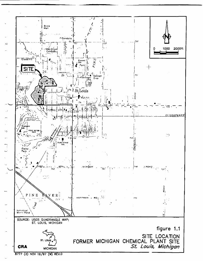
On November 18,1982, Velsicol Chemical Corporation (VCC) (the successor to Michigan Chemical Corporation), the United States Environmental Protection Agency, Region V (USEPA), and the current Michigan Department of Natural Resources (MDNR) [the predecessor to the Michigan Department of Environmental Quality (MDEQ)] entered into a Consent Judgment for the remediation of the former Michigan Chemical Corporation Plant Site in St. Louis, Michigan (see Figure 1.1). VCC completed the remedial
activities required by the Consent Judgment for the Piant Site between 1983 and 1984 in accordance with detailed plans and specifications which were prepared pursuant to the Consent Judgment and approved by USEPA and MDNR.
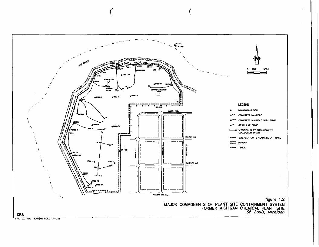
The components of the Plant Site containment system
include:
i) a continuous soil/bentonite containment wall along the entire boundary of the Plant Site with a hydraulic conductivity of I x 10-7 centimeters/ second (cm/s) which is keyed into the underlying clay till a minimum of
30 inches;
ii) a 36-inch thick clay cap (the clay cap is 18 inches in some areas of the Plant Site) with a hydraulic conductivity of 1 x 10⁻⁷ cm/s; and
iii) a groundwater collection drain system within the contained Plant Site to allow for periodic removal of groundwater to ensure the average groundwater level within the soil/bentonite containment wall is maintained below elevation 724.13 feet above mean sea level (AMSL).
The layout of the Plant Site and major components of the containment system are illustrated on Figure 1.2.
Upon completion of the Plant Site remediation program in 1984, VCC developed, and USEPA/MDNR approved, a Post-Closure Maintenance and Monitoring Plan. This Post-Closure Maintenance and Monitoring Plan outlined provisions for routine and contingency maintenance

following completion of the Plant Site remedial activities, and monitoring at the
site at the frequency and for the duration specified by the Consent Judgment.
VCC has continued to carry out the tasks outlined within the Post-Closure
Maintenance and Monitoring Plan since completion of the Plant Site remediation
in 1984.
On behalf of VCC, Memphis Environmental Center (MEC)
conducted an assessment of the Plant Site containment system in 1996. The
results of this assessment were presented within the document entitled "Final
Containment System Assessment Report". The assessment evaluated three major
components of the containment system:
i) the clay cap;
ii) the soil/bento~te containment wall; and iii) the underlying clay till.
Based on the data collected as part of this assessment it was
concluded that the containment system is performing in accordance with the design requirements and construction specifications outlined within the Consent
Judgment. Although some minor weathering of the upper portions of the clay
cap has occurred in a limited number of locations of the Plant Site, the overall
integrity of the clay cap has not been compromised and the clay cap is achieving the desired effect to enhance surface water runoff and control infiltration of
precipitation.
In order to help ensure the long-term integrity of the clay
cap, VCC intends to conduct cap maintenance activities to address the limited
number of areas of the clay cap where recent testing has shown increases in the
hydraulic conductivity of the clay.
The following report presents a Work Plan which describes
the tasks VCC will carry out to complete the maintenance activities on the clay
cap. A description of the tasks to be completed and the quality control testing
that will be carried out during field activities is presented. Throughout these
maintenance activities VCC will complete all work in accordance with the

original design specifications outlined in the Consent Judgment and the Post-Closure Maintenance and Monitoring Plan.

2.0 DESIGN AND PERFORMANCE REOUIREMENTS
2.1 GENERAL
The Consent Judgment specified the design requirements for
the containment system. Details of these specific requirements were described within the detailed plans and specifications for the Plant Site remediation and the
Post-Closure Maintenance and Monitoring Plan which were approved by USEPA/MDNR. The maintenance tasks described within this Work Plan will be
carried out to ensure that the design requirements outlined within the Consent
Judgment and the Post Closure Maintenance & Monitoring Plan are met. These
design requirements are described in the following sections.
2.2 CONSENT JUDGMENT DESIGN/ CONSTRUCTION REQUIREMENTS
The plans and specifications that were developed pursuant to the Consent Judgment by VCC, and approved by USEPA/MDNR prior to
initiation of the Plant Site remediation in 1983, described in detail the method of
installation of the clay cap and all testing and quality control procedures. These
plans and specifications included, as a minimum, the following design criteria
and construction specifications specifically related to the clay cap:
i) a particle size gradation for capping material such that material having V
less that 18 percent of the soil particles smaller than 0.005 millimeters in
diameter and having a minimum of 45 percent fines passing the 200 sieve (clay, classified as CL or ML under the Unified Soils Classification System
or defined by ASTM D421-58 and D422-63 procedures) is placed in the
lower 1.5 feet of cap; and material having more than 18 percent of the soil particles smaller than 0.005 millimeters in diameter and having a
minimum of 45 percent fines passing 200 sieve (clay, classified as CL or
ML under the Unified Soils Classification System or as defined by
ASTM D-421-58 and D-422-63 vrocedures) is placed in the upper 1.5 feet
of cap. Determination of particle size distribution for use as capping
material at the main Plant Site shall be made for a minimum of one sample for each 10,000 cubic yards of material placed;
ii) an on-site quality control program to assure proper spreading and mixing
of capping material;
iii) compaction to achieve 1 x le7 cm/s hydraulic conductivity, or less;
iv) compaction of capping material in place in 6-inch lifts;
v) utilization of the MHO-T-99-671 or Michigan Cone Test MDOT Method
to establish control density. Density and moisture content of the capping
material will be determined in the field by, as a minimum, one test for
each 1,000 cubic yards of clay placed, with no less than one test for each
day of operation and per each layer of clay placed. Density shall be
determined by nuclear method ASTM-D-2922 or rubber balloon method
ASTM-D-2167-66. Determination of Atterberg limits and plastic limit, in
accordance with ASTM-Dm, shall be made at a minimum of one sample
per each 10,000 cubic yards of capping material placed. Redetermination
of Proctor Density of the capping material by either a One Point T-99
Compaction Test or a Five Point Compaction Test shall be performed whenever the texture of the capping material changes, or once every
5,000 cubic yards of capping material obtained from a given borrow
source.
In order to establish the compactive effort required to
achieve a hydraulic conductivity of 1 x 10⁻⁷ cm/s, or less, VCC developed density
versus permeability relationships as part of the detailed design development.
This testing was carried out in accordance with a triaxial consolidation test
carried out with a saturated sample and back pressure in accordance with
ASTM-D-2850. Calculations of test results were performed as outlined in the reference test "Laboratory Soils Testing", Department of Army Engineering
Manual EM-1110-2-1906. The results of this testing were incorporated into the detailed plans and specifications which were approved by USEPA and MDNR.
Based on this testing it was determined that the hydraulic conductivity of 1 x cm/s, or less, would be achieved if the clay cap was compacted to

98 percent Modified Proctor Density at a moisture content of f l percent of its optimum moisture content.
Regular quality control testing was carried out throughout
the duration of the clay cap installation to ensure that the above listed design criteria were being met. This quality control testing was observed and reviewed regularly in the field by MDNR representatives. Based on this testing it was
concluded that the clay cap was installed in accordance with the Consent Judgment design requirements.
2.3 CONTAINMENT SYSTEM ASSESSMENT REPORT
w In an effort to address some concerns raised by
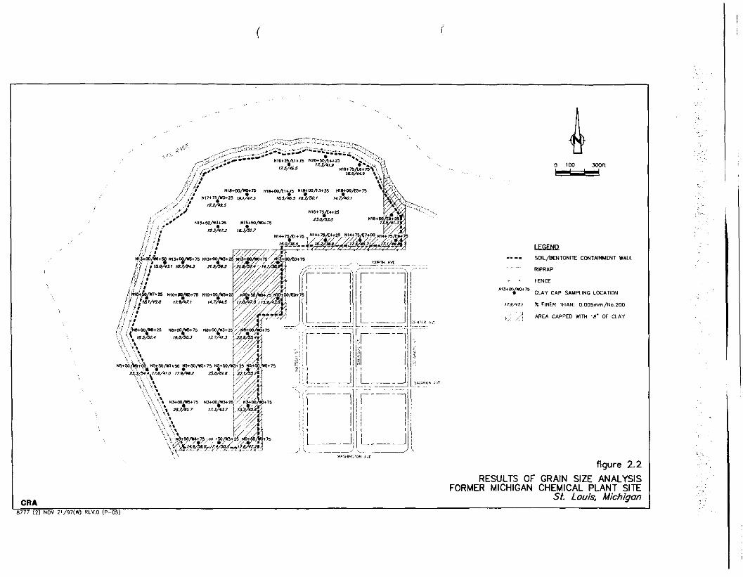
USEPA/MDEQ concerning the Plant Site containment system, MEC on behalf of VCC, conducted an assessment of the containment system in 1996. As part of this assessment MEC collected samples of the upper half of the clay cap for hydraulic conductivity and grain size testing. This sample collection was completed on a predetermined 250-foot grid as shown on Figure 2.1. In total this grid layout produced 41 sampling locations with 27 located in areas where a 36-inch clay cap was placed and 14 located in areas where an 18-inch clay cap
was placed.
At each of the 27 sampling locations within the 36-inch clay V cap, samples of the top 18 inches of the clay cap were collected using 3-inch diameter Shelby tubes. At each of the 14 sampling locations within the 18-inch clay cap, samples of the top 12 inches of the clay cap were collected using 3-inch Shelby tubes. All collected clay cap samples were analyzed for hydraulic
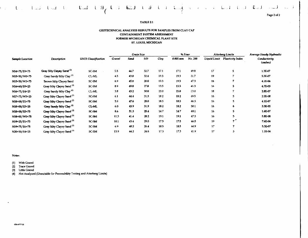
conductivity (ASTM Method D5084), grain size (ASTM Method D422) and Atterberg Limits (ASTM Method D4318). The results of this testing are summarized in Table 2.1. Of the 41 samples collected, grain size analysis were completed on all 41 samples. Hydraulic conductivity and Atterberg Limits were run on 35 of the 41 samples collected. Six of the collected clay samples could not be tested for hydraulic conductivity and Atterberg Limits due to poor sample
recovery or poor sample quality. Table 2.1 summarizes the results of this

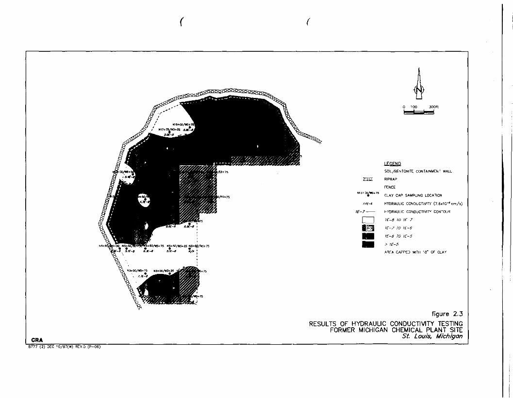
sampling program. The results of the grain size analysis and hydraulic
conductivities are also shown on Figures 2.2 and 2.3, respectively.
For purposes of evaluating maintenance requirements on the
clay cap, the results of the hydraulic conductivity testing were evaluated. Based
on the data presented in Table 2.1, the average hydraulic conductivity across the Plant Site is 4.1 x 10" cm/s which is more than an order of magnitude greater
than the original design specifications of 1 x lo-' cm/s. Of the 35 samples tested, 10 had hydraulic conductivities greater than 1 x cm/s. All of the remaining
25 sam~les had hydraulic conductivities in the order of magnitude range of 10.'
to 10-8 cm/s. Therefore, for purposes of completing maintenance work on the
cap, any arras represented by soil samples that had a hydraulic conductivity
. - greater than 1 x 10⁻⁶ cm/s will be excavated and recompacted to 1 x 10⁻⁷ cm/s.
Completion of the maintenance work will reduce the average hydraulic
conductivity across the Plant Site bringing it to within the magnitude range of
1 x cm/s.
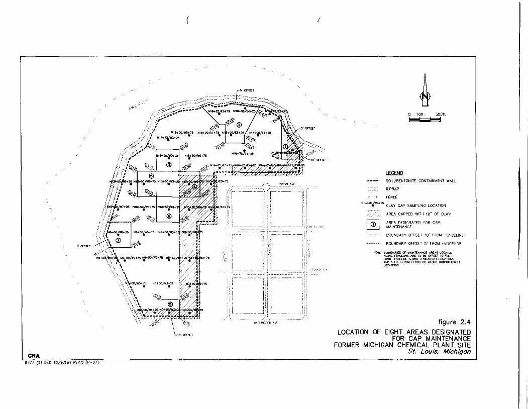
Based on this criteria a total of eight areas will be addressed
under this cap maintenance program. The location and configuration of these
eight areas are shown on Figure 2.4. The shapes of these areas were conservatively established by squaring off all sides of the areas to facilitate field - layout and construction. The limits of each area were established by taking the
rnid-point between sample locations where the hydraulic conductivity was found
\- to be above and below 1 x 10⁻⁶ cm/s. In addition, for areas located adjacent to
the existing chain link security fence, the boundary of the maintenance area was established just short of the fence to avoid damage to the fence during
maintenance activities. The boundaries for the eight-maintenance areas and the
coordinates for the comers of each of the areas to be addressed are shown on
Figure 2.4.
CONFS~CGA-ROVTRS & ASSOCIATES
3.0 MAINTENANCE FIELD PROCEDURES
3.1 SCOPE OF WORK
The maintenance activities will include excavating and
recompacting the existing clay cap in eight areas of the Plant Site in order to
decrease the overall hydraulic conductivity of the Plant Site clay cap. The eight areas to be addressed are shown on Figure 2.4. All excavation, recompaction,
and quality control testing to be completed as part of the maintenance work will
be conducted in accordance with the requirements presented within the original
Consent Judgment, the approved detailed plans and specifications and the
approved Post-Closure Maintenance and Monitoring Plan. The following
sections describe the field procedures to be carried out during this cap
maintenance program.
3.2 ADDITIONAL PRE-MAINTENANCE TESTING
In total eight areas of the Plant Site will be addressed under
this cap maintenance program. These eight areas encompass 10 of the 35 soil
samples where the hydraulic conductivities were greater than 1 x 106 cm/s as
shown in Table 2.1. Of these ten locations, six fall within the original design
criteria for grain size as presented in Section 2.2 and four fall below the original design criteria for grain size for both the 0.005 mrn and No. 200 grain size. The
LI sample location and maintenance area number for these four locations are as
follows:
Samule Location Maintenance Area N10+50/ W3+25 6 N13+00/ W5+75 5 N16+60/E9+25 1 N20+50/E4+25 2
For the four sample locations found to be below the original design criteria, VCC will collect an additional soil sample from the same sample
location prior to initiating the maintenance program to run grain size analysis to
further determine whether the area meets the design criteria. If this second set of
samples demonstrate that the original grain size design criteria are met, the
existing clay within the associated area will be excavated and recompacted. If this resampling shows that both grain size criteria are still below the design
criteria, VCC will utilize, within the associated area, imported clay material from an off-site borrow area which has been determined to meet the original design
specifications (see Section 3.3).
In addition to confirming that the grain size criteria is being
achieved, VCC will collect a sample of the clay material from each of the eight
areas to be addressed under the maintenance program to redetermine the Proctor Density and Optimum Moisture of the clay. The testing results will be
compared to the original detailed design to ensure that the required compactive
effort can be achieved.
The results of all pre-maintenance testing will be provided to
USEPA and MDEQ prior to initiating maintenance field activities.
3.3 SOURCING OF NEW IMPORTED MATERIAL
During the clay cap maintenance program there may be a
need to provide two types of material from off-site borrow sources. If during the stripping of the overlying topsoil and sand, the sand drainage layer cannot be segregated from the topsoil, VCC will replace the sand with imported material.
This sand will be imported clean medium to coarse sand supplied from a source
pre-approved by VCC. As part of approving the source of sand VCC may collect
a sample of the material for Target Compound List (TCL) and Target Analyte
List (TAL) analysis to verlfy that the sand is clean.
If the pre-maintenance testing described in Section 3.2 demonstrates that the existing clay material does not meet the grain size criteria,
VCC will import clay from a pre-approved off-site borrow area. If the use of an
off-site clay borrow area is necessary, VCC will conduct the necessary testing to demonstrate that all of the original design criteria can be met by the new clay
source. This testing will include:
i) grain size distribution; ii) Atterberg Limits;
iii) optimum moisture and density; and
iv) development of density versus hydraulic conductivity relationship to establish minimum compaction required to meet the 1 x 10⁻⁷cm/s
hydraulic conductivity criteria.
In addition to this physical testing, if the off-site clay source
is other than previously used by VCC, sampling of the clay source may be
completed for TCL and TAL analysis to verify that the clay material is clean.
3.4 FIELD PROCEDURES
3.4.1 Lavout of Areas of Cap Maintenance
Prior to initiating field activities as part of the clay cap
maintenance program, VCC will layout each of the eight areas of the Plant Site to
be addressed. For each area the comers will be staked and both horizontal and vertical controls will be surveyed to permanent control points.
3.4.2 Tousoil/Sand Striuuing and Stockpiling -
Once each area has been laid out, VCC's contractor will strip the Binch topsoil layer and Cinch sand layer within the limits shown on
Figure 2.4 to expose the clay cap. To the extent possible the contractor will be required to segregate the topsoil layer and sand layer. The topsoil and sand that
is stripped within each of the eight areas to be addressed will be staged in
separate stockpiles adjacent to the area where the cap maintenance is being
completed. If the sand layer cannot be segregated from the topsoil, the sand will
be blended with the topsoil and new imported sand will be used for restoring the
area.

All stripped topsoil and sand will be stockpiled immediately
adjacent to the maintenance area being recompacted. Topsoil will be stockpiled
on top of the existing ground surface and sand will be stockpiled directly on top
of the existing sand layer along the perimeter of the area being addressed. The
stock piles will be secured as discussed in Section 3.4.5.
During the clay cap maintenance program only one of the
eight designated areas to be addressed will be opened up at one time. VCC's
contractor will not start topsoil and sand stripping in a new area until the previous area is fully recompacted and restored with sand and topsoil.
3.4.3 Excavation and Recompaction of Clav Cap
After the area to be recompacted has been stripped of topsoil
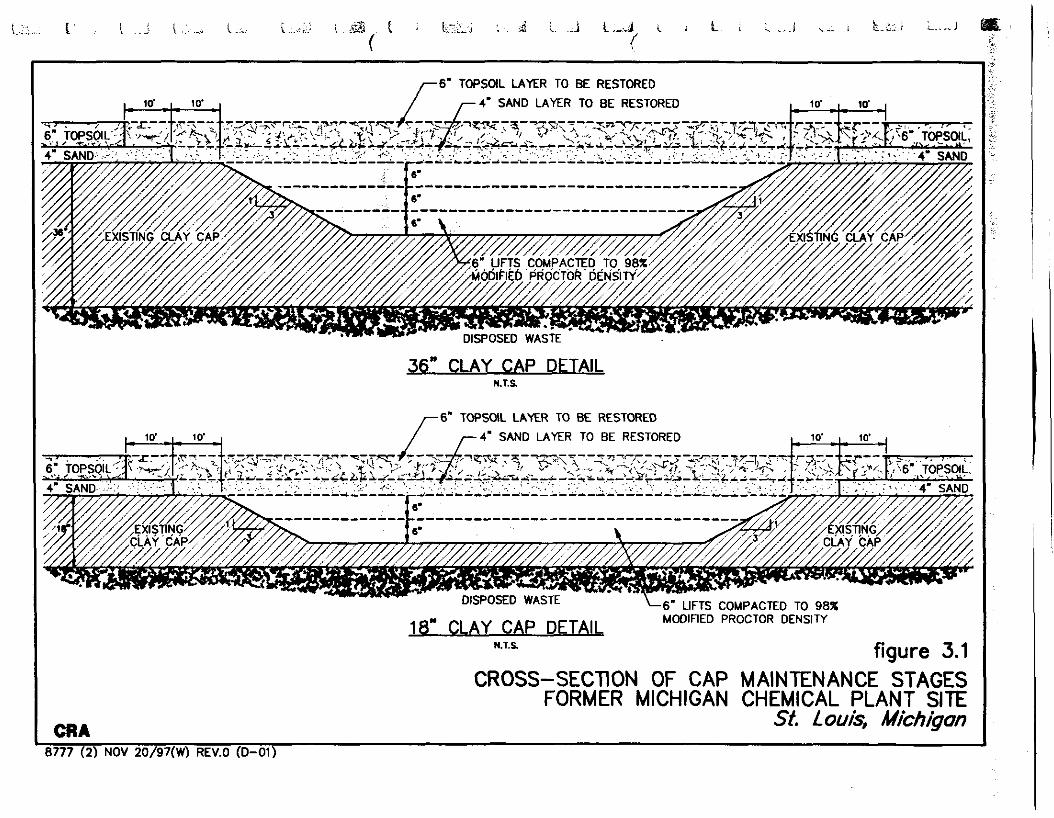
and sand, the top 18 inches of the clay cap will be excavated and stockpiled
adjacent to the area. In the case of Areas 1,4, and 8 the clay cap is only 18 inches
thick; therefore, only the top 12 inches of clay will be excavated and stockpiled.
Care will be taken during the clay excavation, particularly
within the areas where the clay cap is 18-inches, to avoid excavation into the
Plant Site waste. If Plant Site waste is encountered it will be segregated from the
clay material and the depth of excavation will be reduced. Imported clay will be
used to replace the clay cap in these areas to ensure a full 18-inches of clay is placed in the area. When excavating the clay material the edges of the excavation will be tapered at a 3:l slope as illustrated on Figure 3.1. This will
ensure that the portion of clay cap being recompacted will be fully consolidated with the existing undisturbed cap.
Upon excavation of the clay material the base of the
excavation will be compacted, using a sheepsfoot roller, to 98 percent Modified
Proctor Density at a moisture content of +1 percent of optimum moisture. Once
it is verified that the necessary compactive effort has been achieved in the base of
the excavation, the stockpiled clay material will be placed back in the excavation in 6-inch lifts compacted using a sheepsfoot roller, to 98 percent Modified Proctor

Density at a moisture content of fl percent of optimum moisture. Figure 3.7
illustrates the steps to be taken to recompact each of the eight areas.
If it is determined that the existing clay does not meet the
grain size criteria, and off-site imported material is required, the clay material excavated from the area being addressed will be removed from the Plant Site. Following compaction of the base of the excavation, as described above, the
excavation will be backfilled with imported clay material in 6-inch lifts
compacted using a sheepsfoot roller, to 98 percent Modified Proctor Density at a
moisture content of 51 percent of optimum moisture.
3.4.4 Restoration of Sand Drainave Blanket and Topsoil
Once the recompacted clay cap has been restored to its original grade the surface of the clay will be proof rolled with a smooth
drummed roller to provide a smooth surface prior to placing the sand layer. The 4-inch sand layer will be placed over the clay cap using sand from the on-Site
stockpile and/or imported sand from an approved off-site source. The sand
layer will be evenly graded over the clay cap in a Pinch lift.
Upon verification of the sand layer thickness, the entire area
will be restored with 6 inches of topsoil. The topsoil will be graded evenly over
the entire area, preparatory to seeding and mulching. The final placement of cru/ topsoil will be completed in such a manner to ensure that the topsoil within the cap maintenance area is blended into the existing topsoil area.
3.4.5 Seedine. and Mulching
After all eight areas have been recompacted and covered
with topsoil, the areas will be seeded and mulched. The grass seed to be used
will be obtained from a recognized seed house and will be supplied in the
following mix quantities per acre:
90 lbs. Creeping Red Rescue, Ruby
50 ibs.
10 ibs.
20 ibs.
3/4 bu.
30 - 40 lbs.
3.4.6 Control Measures
Blue Grass, Park Variety
White Clover
Perennial Ryegrass
Spring Oats
Ammonium Nitrate
Throughout the duration of the cap
maintenance program VCC will implement control measures to minimize the
generation of dust and the migration of sediments within disturbed areas. These
control measures will include the application of dust suppressants such as water
or calcium chloride to minimize off-Site migration of dust and the installation of silt fencing around each maintenance area prior to commencing the topsoil
stripping. The silt fencing will be installed around each maintenance area such
that all material stockpiles are contained within the silt fence.
3.5 QUALITY CONTROL TESTING
Throughout the duration of the cap maintenance program
VCC will conduct quality control testing consistent with the Consent Judgment
and the approved design plans and specifications. The testing to be completed, the frequency of testing and the testing methods to be completed by VCC are
summarized in Table 3.1.
All quality control testing will be coi~ducted by an independent geotechnical contractor hired by VCC and all testing results will be
recorded by this contractor. Any failures of the design criteria that are identified
by the quality control testing will be immediately rectified and the area in
question will be retested.

3.6 HEALTH AND SAFETY
During this cap maintenance program it is not anticipated
that Site personnel will come in contact with potentially contaminated materials
since the full thickness of the clay cap will not be excavated. However, in order
to ensure the safety of all Site personnel, VCC's contractor will be required to
develop and implement a health and safety plan. This health and safety plan will focus on air monitoring within the work areas to determine whether
protective clothing and respiratory protection will be needed during the course of the work. The final air monitoring and health and safety program will be
designed based on the conditions known to be present at the Plant Site. All work
will be initiated with site personnel being equipped with Level D protection.
W' VCC will monitor air quality in and around each of the eight
areas to be recompacted during maintenance activities. Monitoring will be for
organic vapors using a direct reading organic vapor photonionizer or organic
vapor analyzer. Should monitoring indicate organic vapor concentrations in
excess of 5 parts per million (ppm), personnel will don protective clothing and respiratory protection. The presence of organic vapor concentrations in excess of
25 ppm will result in shutting the maintenance work down, evaluating the cause
of the elevated readings and establishing a course of action.
3.7 FINAL REPORTING
The work being completed within this Work Plan is
considered maintenance activities as described within the Post-Closure
Maintenance and Monitoring Plan. Therefore, a description of the work
completed and a summary of the quality control testing carried out during the
maintenance activities will be provided in the quarterly report that is submitted to USEPA/h4DEQ as part of the Post-Closure Maintenance and Monitoring
Program.

4.0 IMPLEMENTATION SCHEDULE
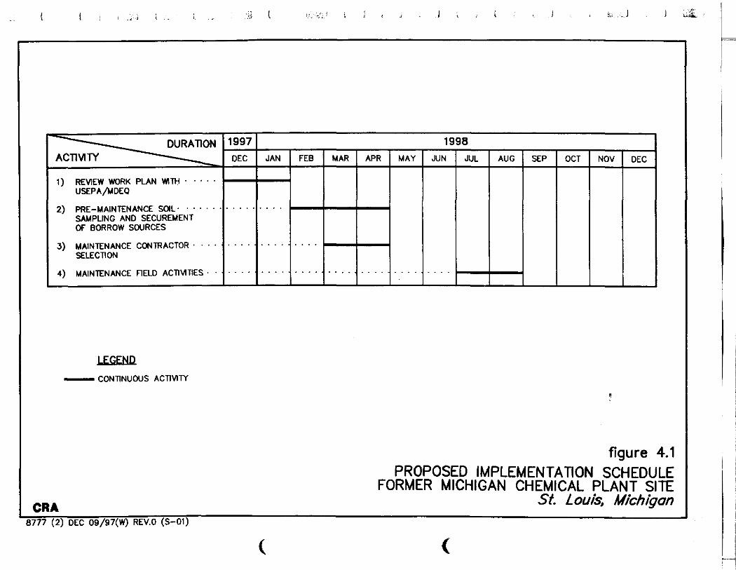
VCC will be scheduling the completion of the proposed cap
maintenance work for approximately July 1998. This should ensure good weather conditions to facilitate field construction activities. In order to be
prepared to start field maintenance activities in July 1998, VCC will conduct all
pre-maintenance testing and contractor selection in the spring of 1998. This
should allow time to secure an off-site clay borrow source, should it be determined necessary. Prior to starting field activities VCC will notify the local
community that the maintenance activities will be completed and what the scope
of the activities will be. Once started, all field maintenance activities are
anticipated to be completed within two morths. A proposed implementation
schedule for the clay cap maintenance program is shown as Figure 4.1.
FIGURES
- - -~ - - - /
'. - . -3- . / . 5 - 8 ,
, \
, \ , ,
- 0 1W . - - - mmn /
/
I
/
/
/
/' lEGEt4Q / MONITORING EU
! ow' CONCRETE YWHOLE
\ ." CONCRETE MANHOLE WTH SUMP
\ mm GRANULAR SUMP
\ a nrnlFrm aAr m o u n ~ w r r r ~
CmLECllON ORIlN
\ ---- SML~WENTONITE CONTAINMENT VNL - \ - RIPRAP
\ - FENCE
\
\
\
\
\
\
\
\ figure 1.2 MAJOR COMPONENTS OF PLANT SlTE CONTAINMENT SYSTEM
FORMER MICHIGAN CHEMICAL PLANT SlTE
CRA St. Louis. Michigon
'8777 (2) NOV 19/97(W) REYO (P-03)

.. .. .. .. - .-
/ - .. ,
\ ,.'
./
0 1W d" ,
, !LGRiR ---- YIL/solTCUllE CCUlUNUENT WALL
. . m w .- . FENE
*''+"Pm (UI cw SWPUNG Lmnm
b-fl AREI CAPPED *ITA t k OF ar.r
i
!
figure 2.1 SAMPLING GRID FOR CONTAINMENT SYSTEM
ASSESSMENT PROGRAM FORMER MICHIGAN CHEMICAL PLANT SITE
CRA St. Louis, Michigan
8777 (2) NOV 21/97(W) REV0 (P-04)
LEEEPlP ---- SaLjBENTONIlE CCUTNNYENT WALL
RIPRAP
FENCE ""'"ia*"
CLAY CAP SAUPUNG LOCATION
#Z9,'77 X FlNER WAN 0 WSrnrnfNa 2 0 0
. 4 AREA CAPPED WIM 18. OF CLAY
figure 2.2 RESULTS OF GRAIN SIZE ANALYSIS
FORMER MICHIGAN CHEMICAL PLANT SITE I CR A
St. Louis, Michigan
8777 (2) NCV 21/97(*0 REV.0 (P-CS)
0 1 0 0 eds"
, LEGEw - SCIL/BLNTONITE CONTAINMENT WALL
. . .~ RIPRAP
f FENCE " " m p C " '
CUI CAP SAMPLING LocAnoN
y,? AREA CAPPED W I H 18. OF CLAY
AREA DESIGNATED FOR CAP MAINTENANCE
. . . . . . . . . BOUNDARY OFFSET 1 0 ' FROM FENCELINE
. . . . . . . BOUNDARY OFFSET 5' FROM FENCELlNE
NOrr B O I * O I R E I OT UUltENAN* A E l S L C C * D ALCUC ~ C L Y N E m TU P WPT $ 0 mr rm" mm*c IIm "PamIINT LCC"'ID(I UID 5 h E T Rc. hNcZU*E llmr -mmI L-nms
figure 2.4 LOCATION OF EIGHT AREAS DESIGNATED
FOR CAP MAINTENANCE FORMER MICHIGAN CHEMICAL PLANT SITE
CRA St. Louis, Michigan 8 7 7 7 (2) DEC 10/97(W) REV0 (P-07)
0 1 0 0
LEcmR SOIL/BENlONITE CONTAINMENT WALL
Piii RIPRAP
FENCE
N''*mf.an5 cL*r CAP SAUPUNC LocAnoN
s - nrnnAuLlc c w o u c n v l n (16rio-'cm/a)
IE-7- HYDRAULIC CONDUCnWPl CONTOUR
0 iE-B TO IE-7
!E-7 10 11-6
m -6 TO !E-5
m > >E-5
AREA CAPPED WTH 18. OF CLAY
figure 2.3
RESULTS OF HYDRAULIC CONDUCTIVITY TESTlNG FORMER MICHIGAN CHEMICAL PLANT SITE
CRA St. Louis, Michigon
8777 (2) OEC 10/97(W) REV0 (P-06)
~~p ~ ~~p
6' TOPSOIL LAYER TO BE RESTORED
4' SAND LAYER TO BE RESTORED
36" CLAY CAP DETAIL KT.%
6' TOPSOIL LAYER TO BE RESTORED
4' SAND LAYER TO BE RESTORED
18 CLA " Y CAP DETAIL MODIFIED PROCTOR DENSITY
N.1.S figure 3.1 CROSS-SECTION OF CAP MAINTENANCE STAGES
FORMER MICHIGAN CHEMICAL PLANT SITE CRA St. Louis, Michigan
8777 (2) NOV 20/97(W) REV.0 (D-01)
LEGEND - CONTINUOUS ACTIVITY
figure 4.1 PROPOSED IMPLEMENTATION SCHEDULE
FORMER MICHIGAN CHEMICAL PLANT SITE CR A St. L ouls, Michtigom
8 7 7 7 (2) DEC 09/97(W) REV.0 (S-01)
DURAION
. . . . . 1) REWEW WORK PLAN WlTH UKPA/MDEO
2) PRE-MAINTENANCE SOIL. SAMPLING AND SECUREMENT OF BORROW SOURCES
3) MAINENANCE CONTRACTOR SELECTION
4) MAINTENANCE nELD A C n u n E S .
1997
DEC
. . . . . . . . . . . . . . .
. . . . . . . . . . . . . . . . . . .
1998
JAN FEE MAR
. . . . . . . . . . . . . . . . . . . . . . . . . . . . . . . . . . . .
APR MAY JUN JUL AUG SEP OCT NOV DEC
TABLES

TABLE 21
GEOTECHNICAL ANALYSES RESULTS FOR SAMPLES FROM CLAY CAP CONTAINMENT SYSTEM ASSESSMENT
FORMER MICHIGAN CHEMICAL PLANT SITE ST. LOUIS, MICHIGAN
Grnin S i u % Fimrr
Desmption US& c/assi/imtion mae el sand Silt Ciny 0.W5nun No. 2W
Gray Silty Clayey Sand
Gray Sandy Silty &y
Gray Smdy Silty Clay
Gray Silty Clayey Smd
Gray Silty Clayey Smd
Gray Sandy Lean Clay
Gray Sandy Lean Clay
Gray Silty Clayey Sand
Gray Silty Clayey Smd
Gray Smdy Silty Clay
Gray Sandy Silty Clay
Gray Silty aayey Sand
tray and^ silty say Gray Sandy Silty Clay
Gray Silty Sand
Gray Silty Clayey Smd
Brown Silty Clayey Sand
Gray Silty Clayey Smd
Gray Silty Clayey Smd
Gray Sil!y Clayey Smd
Gray Sandy Lean Clay
Brown Sandy Silty Clay
Gray Silty Clayey Sand "' Gray Silty Sand
Gray Silty Clayey Sand"'
Gray Silty Clayey Sand "' Grey Silty aayey Sand 'I'
SCSM
CL-ML
CLML
SCSM
SC-SM
CL
CL
CL
SCSM
9 - S M
CL-ML
G M L
SCSM
CL-ML
CL-ML
SM
9 S M
SC-SM
SC-SM
SC-SM
SCSM
CL
CL-ML
SC-SM
SM
SCSM
SC-SM
T - S M
Attrrbrg Limits L;quid Lim;t P las t idy In&*
18 6
16 5
18 6
16 5
16 6
20 9
NA NA
20 9
16 5
16 6
18 7
18 7
15 4
17 5
16 5
NA NA
16 6
16 5
16 6
17 7
NA NA
19 8
18 7
20 5
16 4
NA NA
NA NA
NA NA
(11 With Gravel
TABLE Zl
GEOTECHNICAL ANALYSES RESULTS FOR SAMPLES FROM CLAY CAP CONTNNMENT SYSTEM ASSESSMENT
FORMER MICHIGAN UiEMICAL PLANT SITE ST. LOUIS, MICHIGAN
G n i n Sire %Fimr Attrrbq-Limitr Amrn~e stead&! H y d m ~ l i c
lXIrriptim USCFClss i / io l t im Gram1 Silt Clay 0.005 mm No. 200 Liquid Limit P b t i t i l y I n k C o n d u c t l ~ i g ( ~ u E )
Gray Shy Clayey Sand "' G n y Sandy Silty Clay "' Bmrm Silty Clayey Sand
G n y Silty G y e y S.nd "' G n y Sandy Silty Clay "' Gray Silty Clayey Smd"'
Gray Silty Clayey Sand
c n y S . n d y ~ t y ~ ~ " '
Gray Silty m y e y Sand In
Gmy SilqClayey Smd'"
Gray SiltyClayey Sand"'
G n y Silty Clayey Sand '" Gray Silty Clayey Sand "'
X S M
a-ML
SCSM
X S M
CL-ML
SCSM
X S M
G M L
X-SM
X S M
SCSM
SCSM
SCSM
. . (2) Trace Gravel (3) Little Gravel
(4) Not Analyzed (Unsuitable for P-ability Teriing and Atterberg M b )

TABLE 3.1
SUMMARY OF QUALITY CONTROL TESTING FORMER MICHIGAN CHEMICAL PLANT SITE
ST. LOUIS, MICHIGAN
Type of Tes t
A) Re-Maintenance Testing
Grain Size
Proctor Density
Optimum Moisture
Density vs. Hydraulic Conductivity
B) Maintenance Testing
Proctor Density
Optimum Moisture
Maximum Density and Moisture
Standard Frequency of Test
ASTM D422 (1) (2)
ASTM D698 5.000 c.y. (3)
ASTM D3017 5,000 c.y. (3)
ASTM D5084 (Method C) 10,000c.y. (4)
once per area
once per area
1.000 c.y. or once per 6- inch lift
Criteria
>45% passing No. 200 Sieve >18% passing 0.005 mm Sieve
as measured
as measured
as measured
as measured
98% Modified Proctor Density or as determined for imported
material during Pre-Maintenance Testing (see Note 4)
Notes:
(1) Grain Size testing during pre-maintenance testing will be conducted in four of the eight areas to determine if existing clay material can be used or imported material is required.
(2) If imported clay is needed grain-size analysis will be conducted for every 10,000 c.y. of clay required to verify quality of source.
(3) Proctor Density and Optimum Moisture will be determined in all areas where existing clay will recompacted. If new off-Site clay sources are required, Proctor Density and Optimum Moisture will be determined for every 10,000 c.y. of clay brought to the Site.
(4) Density vs. hydraulic conductivity relationship will be determined if imported clay is needed at a f q u e n c y of one test for each 10,000 c.y. of imported clay brought to the Site.