Embed Size (px)
Citation preview
1
Contents Useful Tips .................................................................................................................................................... 3
1. AutoCAD civil 3D Starting-up Error: ................................................................................................... 3
Tutorial: Creating Alignments ...................................................................................................................... 4
Exercise 1: Creating an Alignment with the Alignment Layout Tools ..................................................... 6
Exercise 2: Adding Free Curves and Spirals to an Alignment ................................................................ 10
Exercise 3: Adding Floating Curves to an Alignment ............................................................................ 13
Tutorial: Editing Alignments ...................................................................................................................... 20
Exercise 4: Editing the Layout Parameter Values of an Alignment ....................................................... 21
Exercise 5: Grip Editing an Alignment ................................................................................................... 25
Exercise 6: Applying a Mask to an Alignment ....................................................................................... 29
Tutorial: Working with Offset Alignments ................................................................................................. 35
Exercise 7: Creating Offset Alignments ................................................................................................. 37
Exercise 8: Editing an Offset Alignment ................................................................................................ 41
Exercise 9: Adding a Widening to an Offset Alignment ........................................................................ 45
Exercise 10: Editing an Offset Widening ............................................................................................... 48
OPTIONAL Tutorial: Designing an Alignment that Refers to Local Standards ........................................ 54
Exercise 1: Drawing an Alignment that Refers to Design Criteria ......................................................... 55
Exercise 2: Viewing and Correcting Alignment Design Criteria Violations .......................................... 59
Exercise 3: Working with Design Checks .............................................................................................. 62
Exercise 4: Modifying a Design Criteria File ......................................................................................... 65
Optional Tutorial: Applying Superelevation to an Alignment .................................................................... 67
Exercise 1: Calculating Superelevation for an Alignment ...................................................................... 68
Exercise 2: Calculating Superelevation for an Individual Curve ............................................................ 70
Exercise 3: Creating a Superelevation View ........................................................................................... 73
Exercise 4: Adding and Modifying Superelevation Stations .................................................................. 75
Exercise 5: Editing Superelevation Parameters Graphically .................................................................. 77
2
Alignments Tutorials These tutorials will get you started working with horizontal alignments, which are the basis for modeling roads.
Note:
All drawings used in these tutorials are available in the tutorial drawings folder. If you want to save your work from these tutorials, save the drawings to the My Tutorial Data folder so that you do not overwrite the original drawings.
Topics in this section
Tutorial: Creating Alignments This tutorial demonstrates how to create and modify alignments.
Tutorial: Editing Alignments This tutorial demonstrates some common editing tasks for alignments.
Tutorial: Working with Offset Alignments This tutorial demonstrates how to create and modify offset alignments that are dynamically linked to a centerline alignment.
Tutorial: Designing an Alignment that Refers to Local Standards This tutorial demonstrates how to validate that your alignment design meets criteria specified by a local agency.
Tutorial: Applying Superelevation to an Alignment In this tutorial, you will calculate superelevation for alignment curves, create a superelevation view to display the superelevation data, and edit the superelevation data both graphically and in a tabular format.
3
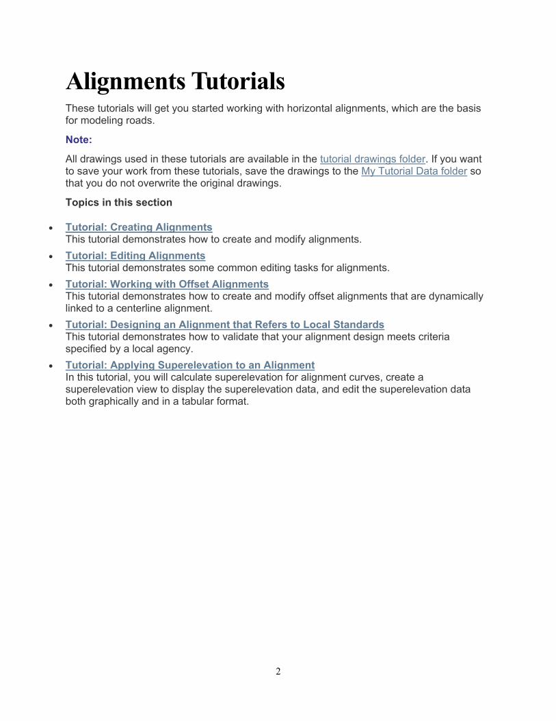
Useful Tips In case you are facing software issues:
1. AutoCAD civil 3D Starting-up Error:
Start Menu - All Apps - Autodesk AutoCAD Civil 3D 2017 - Reset Setting to Default
4
Tutorial: Creating Alignments This tutorial demonstrates how to create and modify alignments.
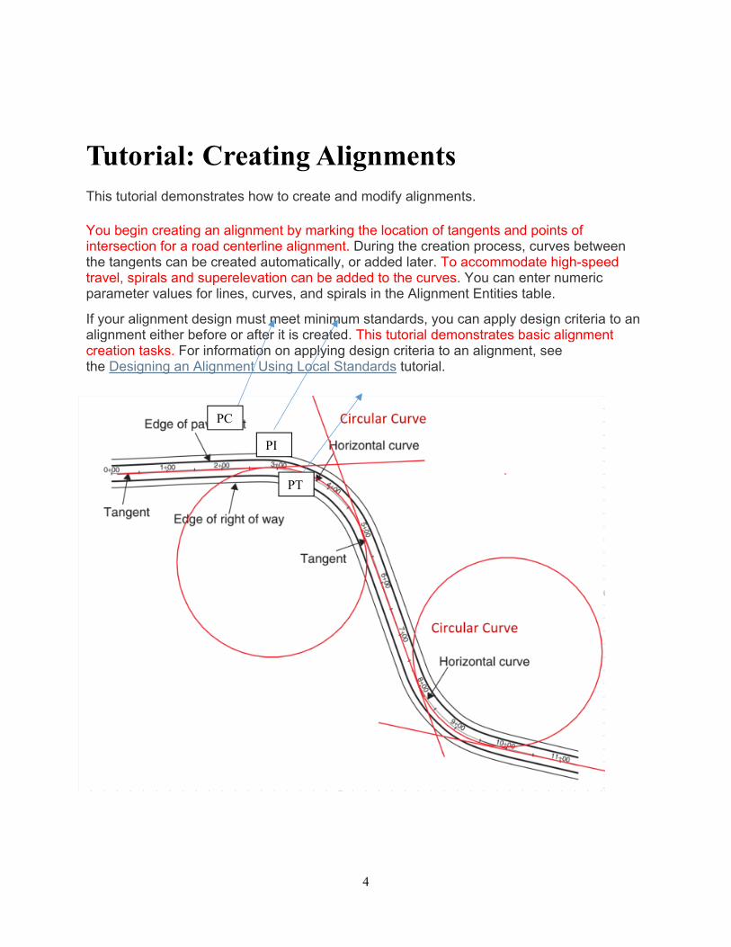
You begin creating an alignment by marking the location of tangents and points of intersection for a road centerline alignment. During the creation process, curves between the tangents can be created automatically, or added later. To accommodate high-speed travel, spirals and superelevation can be added to the curves. You can enter numeric parameter values for lines, curves, and spirals in the Alignment Entities table.
If your alignment design must meet minimum standards, you can apply design criteria to an alignment either before or after it is created. This tutorial demonstrates basic alignment creation tasks. For information on applying design criteria to an alignment, see the Designing an Alignment Using Local Standards tutorial.
PC
PI
PT
5
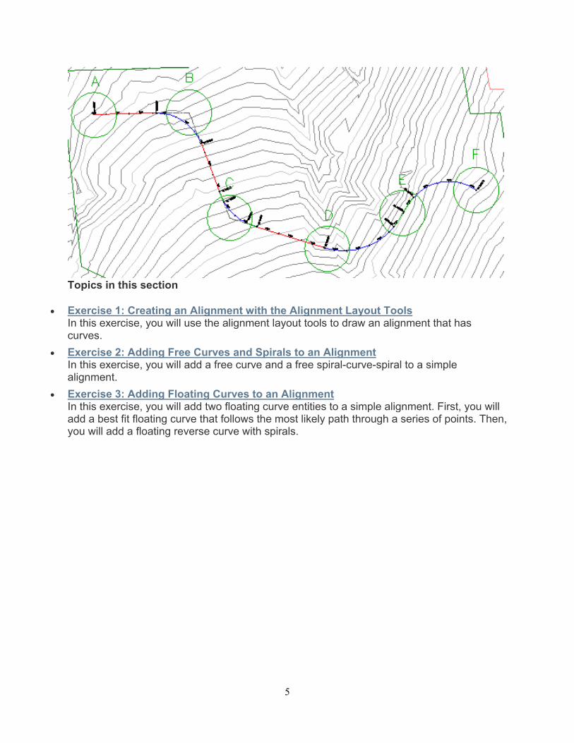
Topics in this section
Exercise 1: Creating an Alignment with the Alignment Layout Tools In this exercise, you will use the alignment layout tools to draw an alignment that has curves.
Exercise 2: Adding Free Curves and Spirals to an Alignment In this exercise, you will add a free curve and a free spiral-curve-spiral to a simple alignment.
Exercise 3: Adding Floating Curves to an Alignment In this exercise, you will add two floating curve entities to a simple alignment. First, you will add a best fit floating curve that follows the most likely path through a series of points. Then, you will add a floating reverse curve with spirals.
6
Exercise 1: Creating an Alignment with the Alignment Layout Tools
In this exercise, you will use the alignment layout tools to draw an alignment that has curves.
Specify alignment properties
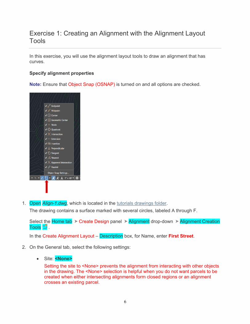
Note: Ensure that Object Snap (OSNAP) is turned on and all options are checked.
1. Open Align-1.dwg, which is located in the tutorials drawings folder.
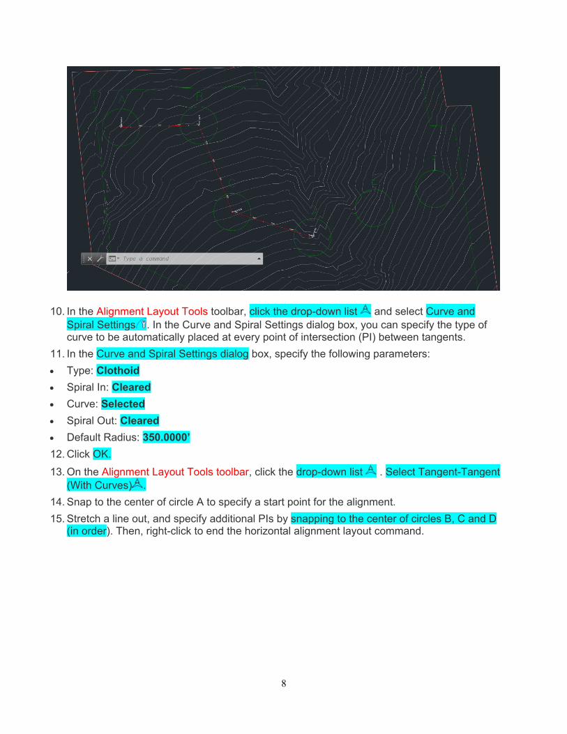
The drawing contains a surface marked with several circles, labeled A through F. Select the Home tab Create Design panel Alignment drop-down Alignment Creation Tools .
In the Create Alignment Layout – Description box, for Name, enter First Street.
2. On the General tab, select the following settings:
Site: <None>
Setting the site to <None> prevents the alignment from interacting with other objects in the drawing. The <None> selection is helpful when you do not want parcels to be created when either intersecting alignments form closed regions or an alignment crosses an existing parcel.
7
Alignment Style: Layout
Alignment Layer: C-ROAD
Alignment Label Set: Standard
3. In the same dialog box (Create Alignment Layout) Box Select the Design Criteria tab.
The Starting Design Speed value specifies the default design speed at the alignment starting station. Design speeds can be specified at other stations along the alignment. If no other design speeds are specified, the Starting Design Speed is applied to the entire alignment. Accept the default Starting Design Speed value for this exercise. The other options on this tab are used only if you want to ensure that the alignment design meets specified design criteria. You do not apply design criteria to the alignment in this exercise. Leave this box unchanged. You will learn how to use the design criteria feature in the Designing an Alignment that Refers to Local Standards tutorial.
4. Click OK.
The Alignment Layout Tools toolbar is the displayed. It includes the controls required to create and edit alignments.
Draw the alignment
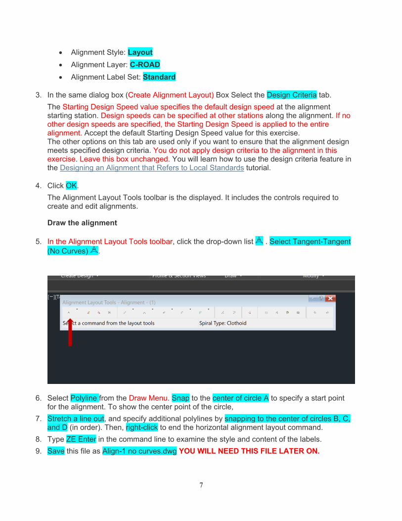
5. In the Alignment Layout Tools toolbar, click the drop-down list . Select Tangent-Tangent (No Curves) .
6. Select Polyline from the Draw Menu. Snap to the center of circle A to specify a start point for the alignment. To show the center point of the circle,
7. Stretch a line out, and specify additional polylines by snapping to the center of circles B, C, and D (in order). Then, right-click to end the horizontal alignment layout command.
8. Type ZE Enter in the command line to examine the style and content of the labels.
9. Save this file as Align-1 no curves.dwg YOU WILL NEED THIS FILE LATER ON.
8
10. In the Alignment Layout Tools toolbar, click the drop-down list and select Curve and Spiral Settings . In the Curve and Spiral Settings dialog box, you can specify the type of curve to be automatically placed at every point of intersection (PI) between tangents.
11. In the Curve and Spiral Settings dialog box, specify the following parameters:
Type: Clothoid
Spiral In: Cleared
Curve: Selected
Spiral Out: Cleared
Default Radius: 350.0000’
12. Click OK.
13. On the Alignment Layout Tools toolbar, click the drop-down list . Select Tangent-Tangent (With Curves) .
14. Snap to the center of circle A to specify a start point for the alignment.
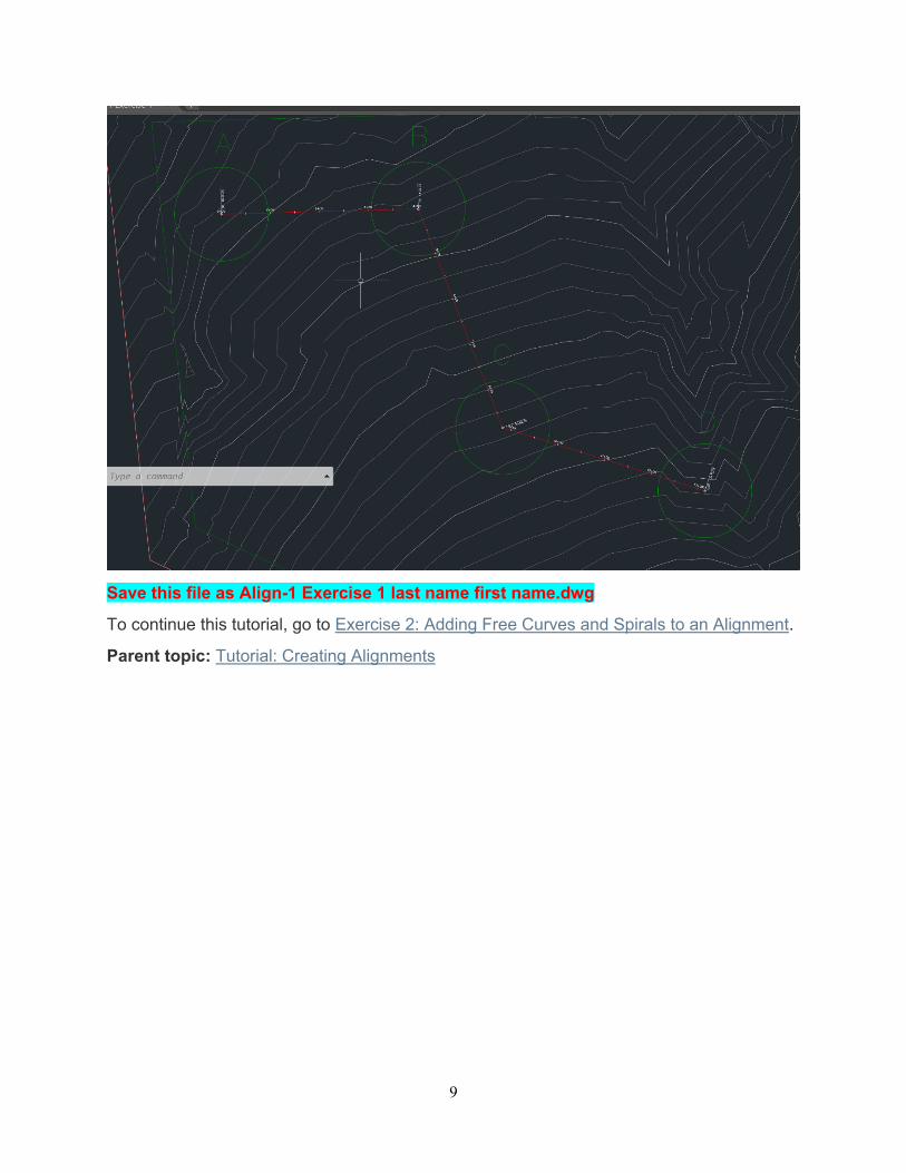
15. Stretch a line out, and specify additional PIs by snapping to the center of circles B, C and D (in order). Then, right-click to end the horizontal alignment layout command.
9
Save this file as Align-1 Exercise 1 last name first name.dwg
To continue this tutorial, go to Exercise 2: Adding Free Curves and Spirals to an Alignment.
Parent topic: Tutorial: Creating Alignments
10
Exercise 2: Adding Free Curves and Spirals to an Alignment
In this exercise, you will add a free curve and a free spiral-curve-spiral to a simple alignment.
The drawing contains a simple alignment consisting of three tangents. In the next few steps, you will add free curves at circles B and C.
This exercise continues from Exercise 1: Creating an Alignment with Spirals and Curves.
Add a free curve between two tangents
This exercise continues with Align-1 no curves.dwg, with modifications you made in the previous exercise.
1. Open the file Align-1 no curves.dwg
2. Set your drawing window so that you can see circles B and C on the surface.
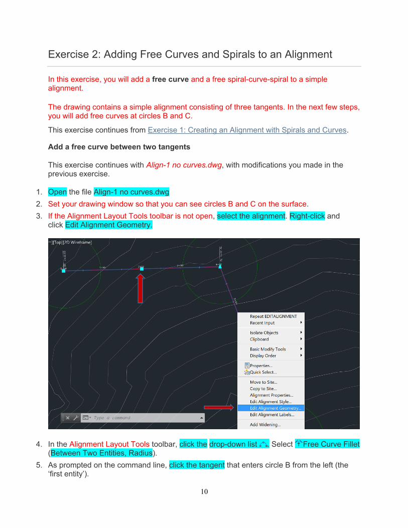
3. If the Alignment Layout Tools toolbar is not open, select the alignment. Right-click and click Edit Alignment Geometry.
4. In the Alignment Layout Tools toolbar, click the drop-down list . Select Free Curve Fillet (Between Two Entities, Radius).
5. As prompted on the command line, click the tangent that enters circle B from the left (the ‘first entity’).
11
6. Click the tangent that exits from circle B on the right (the ‘next entity’).
7. Press Enter to select the default value of a curve less than 180 degrees.
8. Enter a radius value of 200. The curve is drawn between the tangents as specified.
Add a free spiral-curve-spiral between two tangents
1. In the Alignment Layout Tools toolbar, click the arrow next to . Select Free Spiral-Curve-Spiral (Between Two Entities).
2. As prompted on the command line, click the tangent that enters circle C from the left (the ‘first entity’).
3. Click the tangent that exits circle C on the right (the ‘next entity’).
4. Press Enter to select the default value of a curve less than 180 degrees.
5. Enter a radius value of 200.
6. Enter a spiral in length of 50.
7. Enter a spiral out length of 50.
Note:
Notice that default values that are shown on the command line.
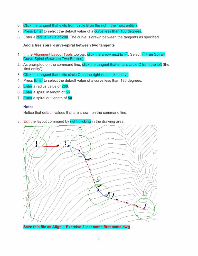
8. Exit the layout command by right-clicking in the drawing area.
Save this file as Align-1 Exercise 2 last name first name.dwg

12
13
Exercise 3: Adding Floating Curves to an Alignment
In this exercise, you will add two floating curve entities to a simple alignment. First, you will add a best fit floating curve that follows the most likely path through a series of points. Then, you will add a floating reverse curve with spirals.
The initial drawing shows a simple alignment consisting of three tangents with curves. In the next few steps, you will add two floating curves to the end of the alignment.
This exercise continues from Exercise 3: Adding Free Curves and Spirals to an Alignment.
Add a floating curve by best fit to the alignment
Note:
This exercise uses Align-1 Exercise 2.dwg with the modifications you made in the previous exercise.
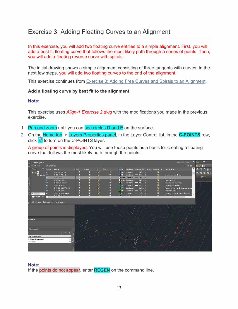
1. Pan and zoom until you can see circles D and E on the surface.
2. On the Home tab Layers Properties panel, in the Layer Control list, in the C-POINTS row, click to turn on the C-POINTS layer.
A group of points is displayed. You will use these points as a basis for creating a floating curve that follows the most likely path through the points.
Note: If the points do not appear, enter REGEN on the command line.
14
3. Click X to close the Layer Properties Menu.
4. If the Alignment Layout Tools toolbar is not open, select the alignment. Right-click and click Edit Alignment Geometry.
5. In the Alignment Layout Tools toolbar, click the drop-down list . Select Floating Curve - Best Fit.
6. As prompted on the command line, click the tangent that ends in circle D (the ‘entity to attach to’).
7. In the Curve By Best Fit dialog box, make sure that From COGO Points is selected. Click OK.
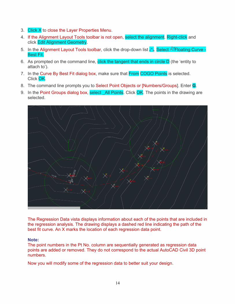
8. The command line prompts you to Select Point Objects or [Numbers/Groups]. Enter G.
9. In the Point Groups dialog box, select _All Points. Click OK. The points in the drawing are selected.
The Regression Data vista displays information about each of the points that are included in the regression analysis. The drawing displays a dashed red line indicating the path of the best fit curve. An X marks the location of each regression data point.
Note: The point numbers in the Pt No. column are sequentially generated as regression data points are added or removed. They do not correspond to the actual AutoCAD Civil 3D point numbers.
Now you will modify some of the regression data to better suit your design.
15
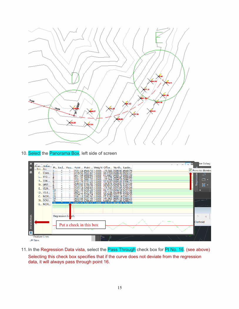
10. Select the Panorama Box, left side of screen
11. In the Regression Data vista, select the Pass Through check box for Pt No. 16. (see above)
Selecting this check box specifies that if the curve does not deviate from the regression data, it will always pass through point 16.
Put a check in this box
16
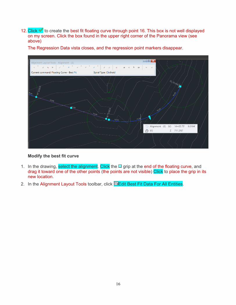
12. Click to create the best fit floating curve through point 16. This box is not well displayed on my screen. Click the box found in the upper right corner of the Panorama view (see above)
The Regression Data vista closes, and the regression point markers disappear.
Modify the best fit curve
1. In the drawing, select the alignment. Click the grip at the end of the floating curve, and drag it toward one of the other points (the points are not visible) Click to place the grip in its new location.
2. In the Alignment Layout Tools toolbar, click Edit Best Fit Data For All Entities.
17
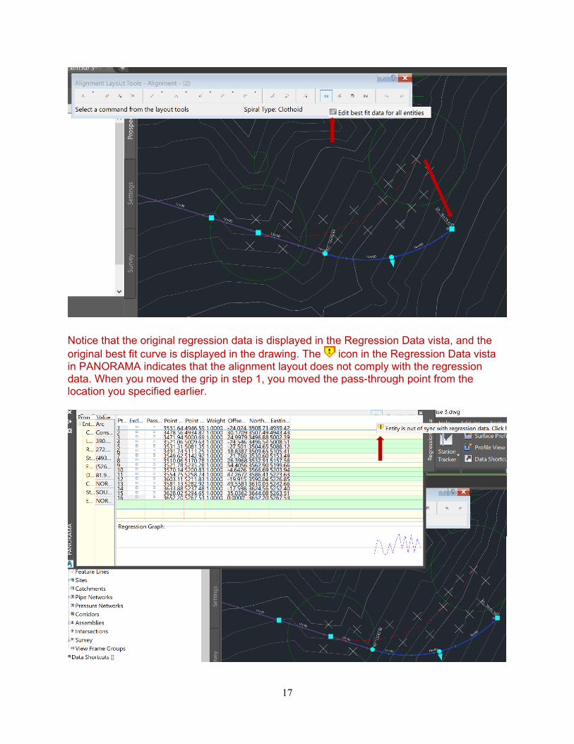
Notice that the original regression data is displayed in the Regression Data vista, and the original best fit curve is displayed in the drawing. The icon in the Regression Data vista in PANORAMA indicates that the alignment layout does not comply with the regression data. When you moved the grip in step 1, you moved the pass-through point from the location you specified earlier.
18
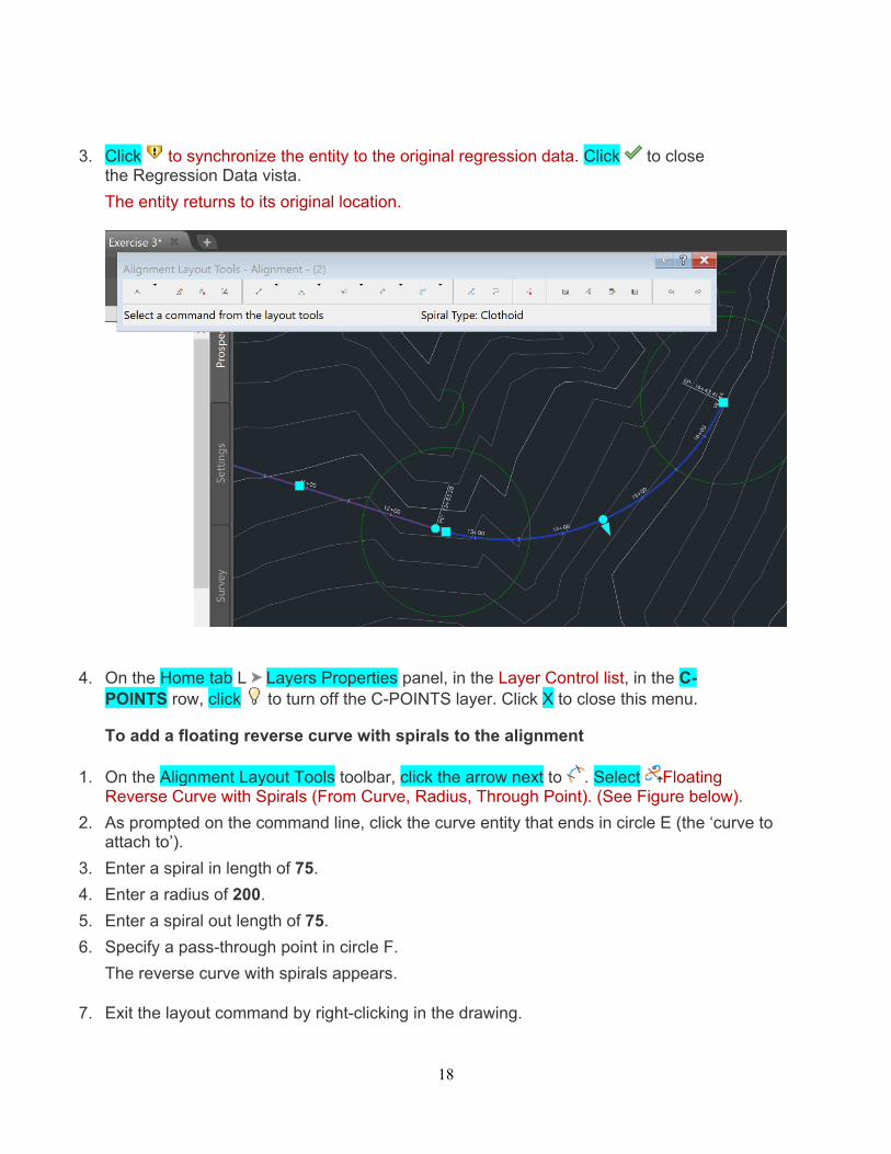
3. Click to synchronize the entity to the original regression data. Click to close the Regression Data vista.
The entity returns to its original location.
4. On the Home tab L Layers Properties panel, in the Layer Control list, in the C-POINTS row, click to turn off the C-POINTS layer. Click X to close this menu.
To add a floating reverse curve with spirals to the alignment
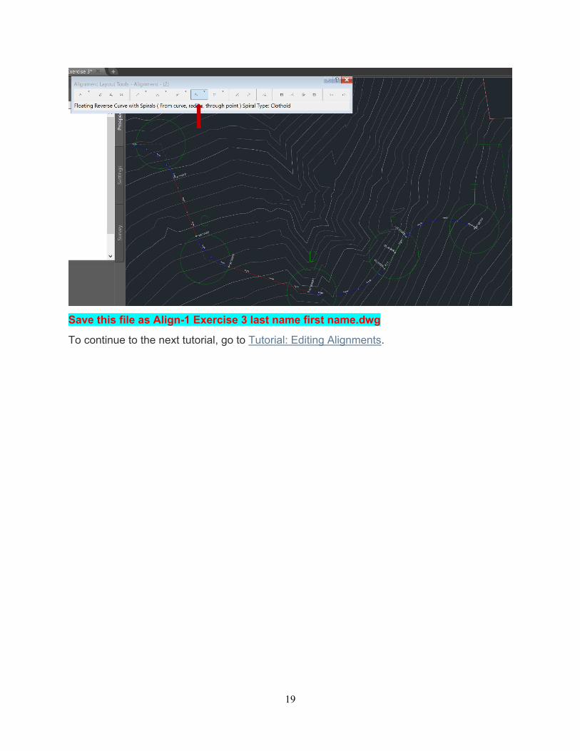
1. On the Alignment Layout Tools toolbar, click the arrow next to . Select Floating Reverse Curve with Spirals (From Curve, Radius, Through Point). (See Figure below).
2. As prompted on the command line, click the curve entity that ends in circle E (the ‘curve to attach to’).
3. Enter a spiral in length of 75.
4. Enter a radius of 200.
5. Enter a spiral out length of 75.
6. Specify a pass-through point in circle F.
The reverse curve with spirals appears.
7. Exit the layout command by right-clicking in the drawing.
19
Save this file as Align-1 Exercise 3 last name first name.dwg
To continue to the next tutorial, go to Tutorial: Editing Alignments.
20
Tutorial: Editing Alignments This tutorial demonstrates some common editing tasks for alignments.
Editing the layout parameter values of an alignment allows you to make fine adjustments to alignment sub-entities. Grip editing provides a convenient method of manually reshaping an alignment.
Topics in this section
Exercise 4: Editing the Layout Parameter Values of an Alignment In this exercise, you will use the Alignment Entities vista and Alignment Layout Parameters dialog box to edit the layout parameter values of an alignment.
Exercise 5: Grip Editing an Alignment In this exercise, you will use grips to move alignment curves.
Exercise 6: Applying a Mask to an Alignment In this exercise, you will hide a portion of an alignment from view.
21
Exercise 4: Editing the Layout Parameter Values of an Alignment
In this exercise, you will use the Alignment Entities vista and Alignment Layout Parameters dialog box to edit the layout parameter values of an alignment.
This exercise continues from the Creating Alignments tutorial.
Note:
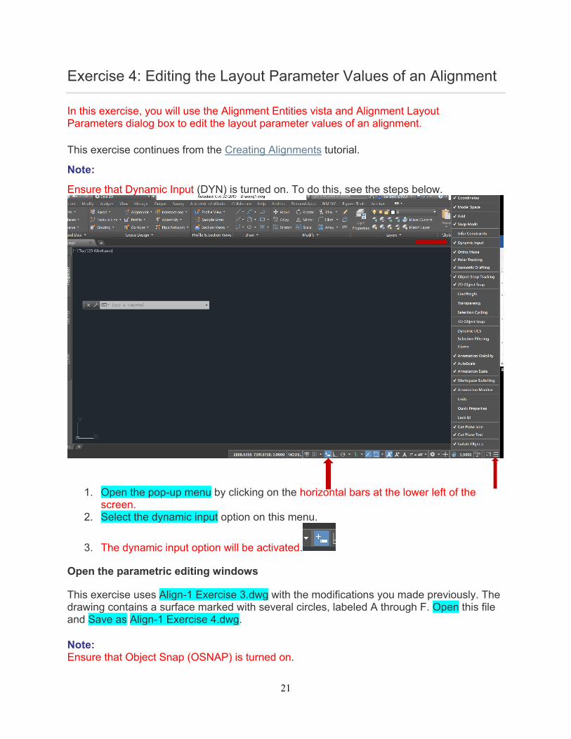
Ensure that Dynamic Input (DYN) is turned on. To do this, see the steps below.
1. Open the pop-up menu by clicking on the horizontal bars at the lower left of the screen.
2. Select the dynamic input option on this menu.
3. The dynamic input option will be activated.
Open the parametric editing windows
This exercise uses Align-1 Exercise 3.dwg with the modifications you made previously. The drawing contains a surface marked with several circles, labeled A through F. Open this file and Save as Align-1 Exercise 4.dwg.
Note: Ensure that Object Snap (OSNAP) is turned on.
22
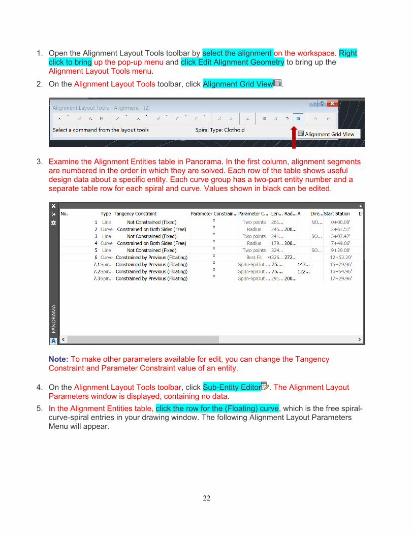
1. Open the Alignment Layout Tools toolbar by select the alignment on the workspace. Right click to bring up the pop-up menu and click Edit Alignment Geometry to bring up the Alignment Layout Tools menu.
2. On the Alignment Layout Tools toolbar, click Alignment Grid View .
3. Examine the Alignment Entities table in Panorama. In the first column, alignment segments are numbered in the order in which they are solved. Each row of the table shows useful design data about a specific entity. Each curve group has a two-part entity number and a separate table row for each spiral and curve. Values shown in black can be edited.
Note: To make other parameters available for edit, you can change the Tangency Constraint and Parameter Constraint value of an entity.
4. On the Alignment Layout Tools toolbar, click Sub-Entity Editor . The Alignment Layout Parameters window is displayed, containing no data.
5. In the Alignment Entities table, click the row for the (Floating) curve, which is the free spiral-curve-spiral entries in your drawing window. The following Alignment Layout Parameters Menu will appear.
23
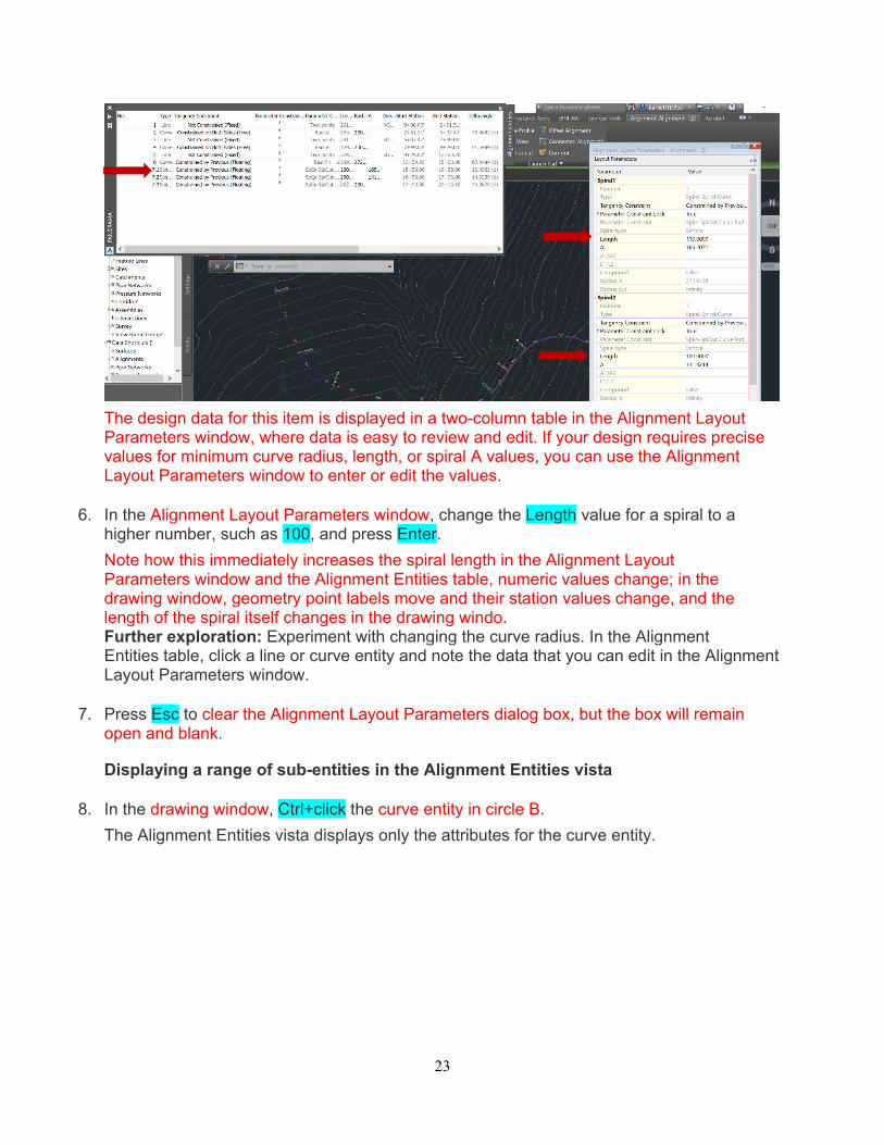
The design data for this item is displayed in a two-column table in the Alignment Layout Parameters window, where data is easy to review and edit. If your design requires precise values for minimum curve radius, length, or spiral A values, you can use the Alignment Layout Parameters window to enter or edit the values.
6. In the Alignment Layout Parameters window, change the Length value for a spiral to a higher number, such as 100, and press Enter.
Note how this immediately increases the spiral length in the Alignment Layout Parameters window and the Alignment Entities table, numeric values change; in the drawing window, geometry point labels move and their station values change, and the length of the spiral itself changes in the drawing windo. Further exploration: Experiment with changing the curve radius. In the Alignment Entities table, click a line or curve entity and note the data that you can edit in the Alignment Layout Parameters window.
7. Press Esc to clear the Alignment Layout Parameters dialog box, but the box will remain open and blank.
Displaying a range of sub-entities in the Alignment Entities vista
8. In the drawing window, Ctrl+click the curve entity in circle B.
The Alignment Entities vista displays only the attributes for the curve entity.
24
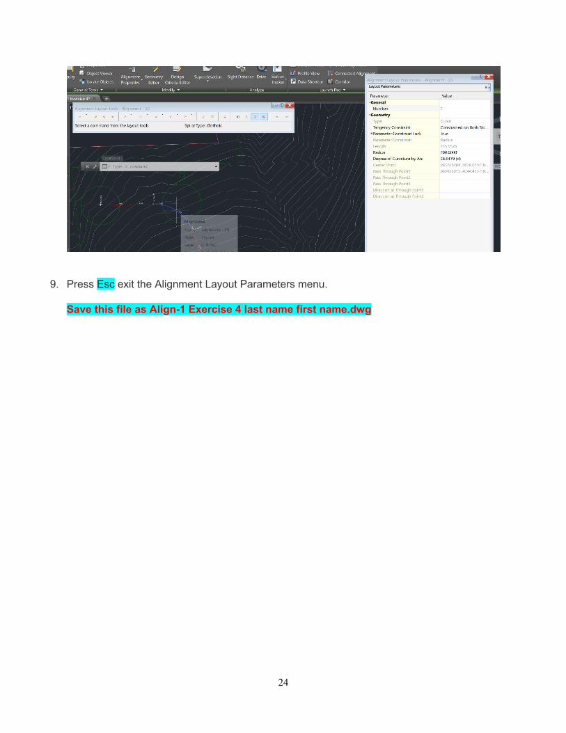
9. Press Esc exit the Alignment Layout Parameters menu.
Save this file as Align-1 Exercise 4 last name first name.dwg
25
Exercise 5: Grip Editing an Alignment
In this exercise, you will use grips to move alignment curves.
You will learn how to grip edit offset and curb return alignments in the Working with Offset and Curb Return Alignments tutorial.
Note: To change the behavior of an entity, you can change the Tangency Constraint and Parameter Constraint value.
This exercise continues from Exercise 1: Editing the Attribute Values of a Horizontal Alignment.
Note:
Ensure that Dynamic Input (DYN) is turned on, and OSNAP is turned off. For more information, see the Using Basic Functionality tutorial.
Grip edit a free curve entity
Note:
This exercise uses Align-1 Exercise 4.dwg with the modifications you made in the previous exercise. Open this file and save as Align-1 Exercise 5.dwg
1. Zoom to the area around circle B.
2. Click the curve in circle B. Blue-colored grips appear at the curve ends, midpoint, and at the point of intersection (PI).
3. Click the midpoint grip at the midpoint of the curve. It turns red.
4. Increase the curve radius, click a new location for the curve to pass through.
Notice that the curves and tangents remain tangent to each other, but both endpoints move along the tangents.
5. Click the radius grip directly above the pass-through point grip and experiment with moving it.
Notice that this grip affects only the curve radius and constrained to the direction of the radius change.
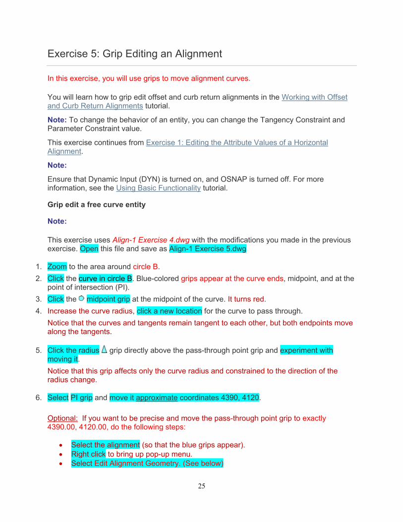
6. Select PI grip and move it approximate coordinates 4390, 4120.
Optional: If you want to be precise and move the pass-through point grip to exactly 4390.00, 4120.00, do the following steps:
Select the alignment (so that the blue grips appear). Right click to bring up pop-up menu. Select Edit Alignment Geometry. (See below)
26
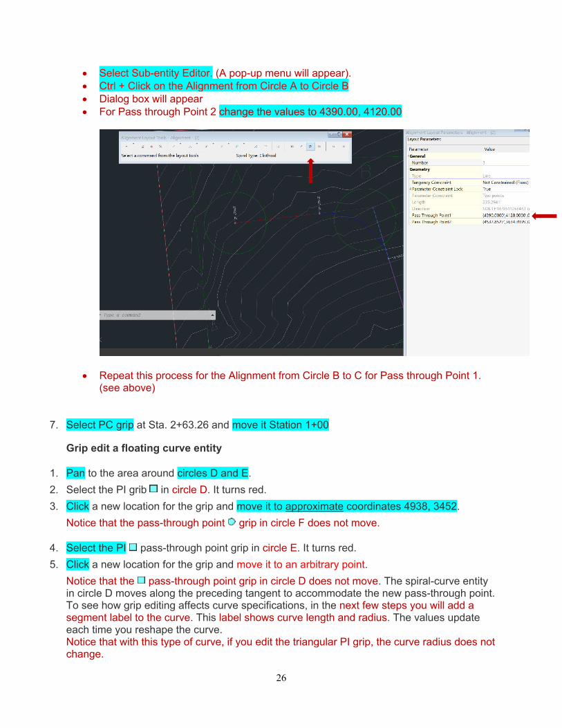
Select Sub-entity Editor. (A pop-up menu will appear). Ctrl + Click on the Alignment from Circle A to Circle B Dialog box will appear For Pass through Point 2 change the values to 4390.00, 4120.00
Repeat this process for the Alignment from Circle B to C for Pass through Point 1. (see above)
7. Select PC grip at Sta. 2+63.26 and move it Station 1+00
Grip edit a floating curve entity
1. Pan to the area around circles D and E.
2. Select the PI grib in circle D. It turns red.
3. Click a new location for the grip and move it to approximate coordinates 4938, 3452.
Notice that the pass-through point grip in circle F does not move.
4. Select the PI pass-through point grip in circle E. It turns red.
5. Click a new location for the grip and move it to an arbitrary point.
Notice that the pass-through point grip in circle D does not move. The spiral-curve entity in circle D moves along the preceding tangent to accommodate the new pass-through point. To see how grip editing affects curve specifications, in the next few steps you will add a segment label to the curve. This label shows curve length and radius. The values update each time you reshape the curve. Notice that with this type of curve, if you edit the triangular PI grip, the curve radius does not change.
27
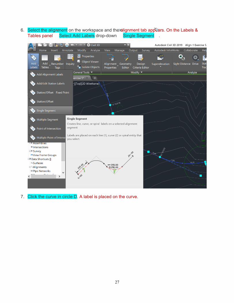
6. Select the alignment on the workspace and the alignment tab appears. On the Labels & Tables panel Select Add Labels drop-down Single Segment .
7. Click the curve in circle D. A label is placed on the curve.
28
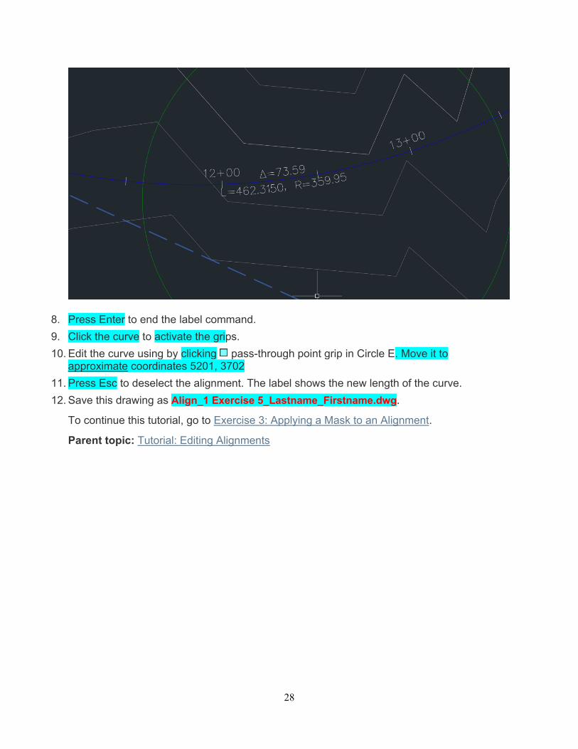
8. Press Enter to end the label command.
9. Click the curve to activate the grips.
10. Edit the curve using by clicking pass-through point grip in Circle E. Move it to approximate coordinates 5201, 3702
11. Press Esc to deselect the alignment. The label shows the new length of the curve.
12. Save this drawing as Align_1 Exercise 5_Lastname_Firstname.dwg.
To continue this tutorial, go to Exercise 3: Applying a Mask to an Alignment.
Parent topic: Tutorial: Editing Alignments
29
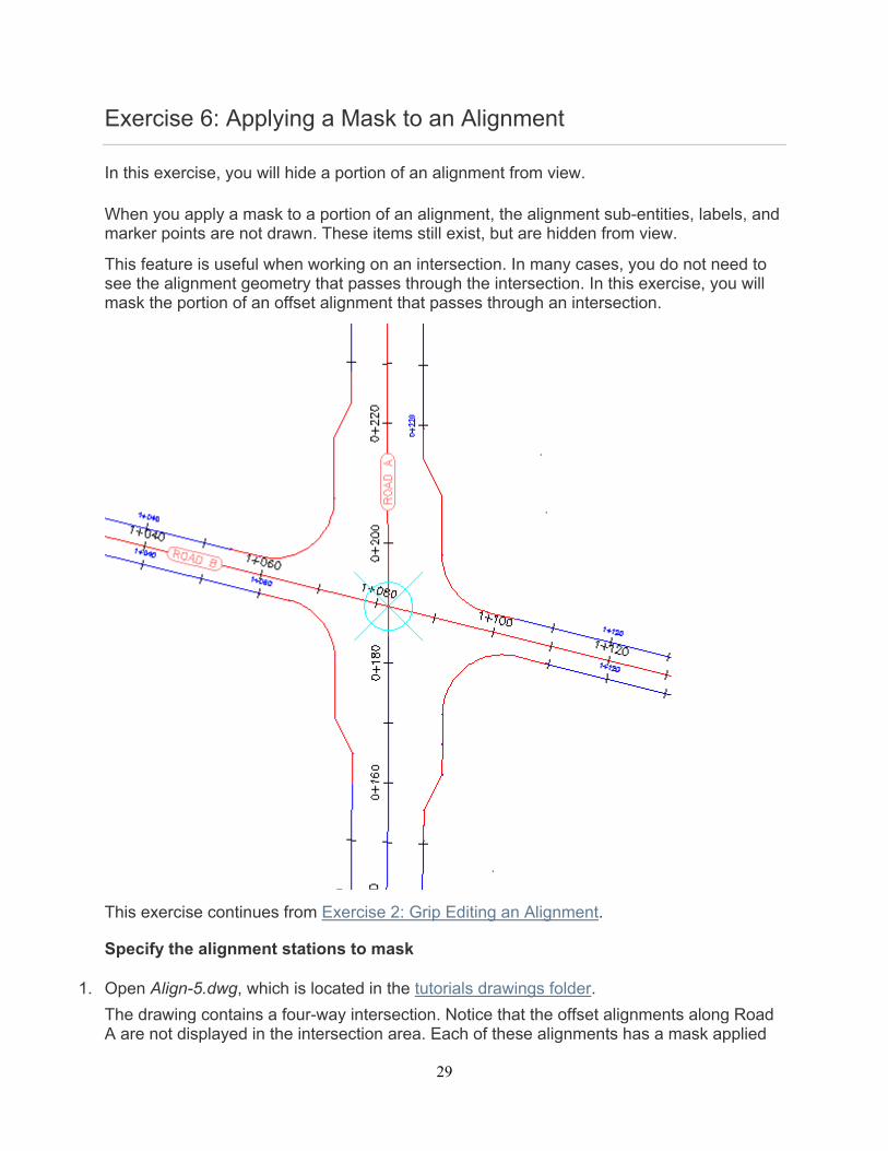
Exercise 6: Applying a Mask to an Alignment
In this exercise, you will hide a portion of an alignment from view.
When you apply a mask to a portion of an alignment, the alignment sub-entities, labels, and marker points are not drawn. These items still exist, but are hidden from view.
This feature is useful when working on an intersection. In many cases, you do not need to see the alignment geometry that passes through the intersection. In this exercise, you will mask the portion of an offset alignment that passes through an intersection.
This exercise continues from Exercise 2: Grip Editing an Alignment.
Specify the alignment stations to mask
1. Open Align-5.dwg, which is located in the tutorials drawings folder.
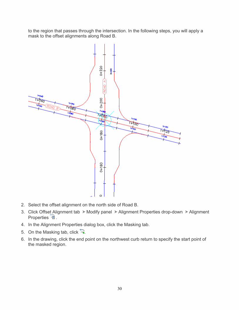
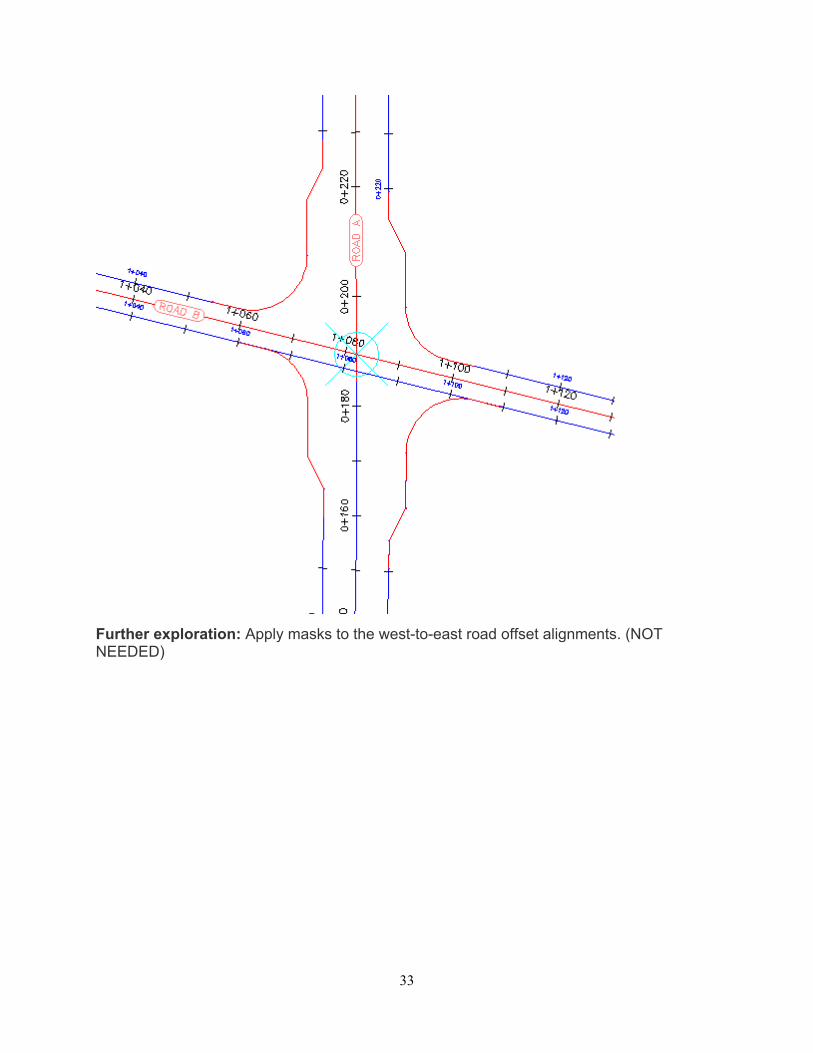
The drawing contains a four-way intersection. Notice that the offset alignments along Road A are not displayed in the intersection area. Each of these alignments has a mask applied
30
to the region that passes through the intersection. In the following steps, you will apply a mask to the offset alignments along Road B.
2. Select the offset alignment on the north side of Road B.
3. Click Offset Alignment tab Modify panel Alignment Properties drop-down Alignment Properties .
4. In the Alignment Properties dialog box, click the Masking tab.
5. On the Masking tab, click .
6. In the drawing, click the end point on the northwest curb return to specify the start point of the masked region.
31
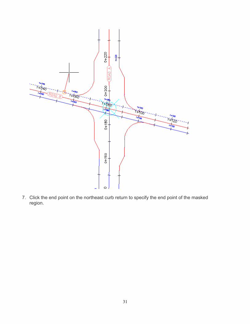
7. Click the end point on the northeast curb return to specify the end point of the masked region.
32
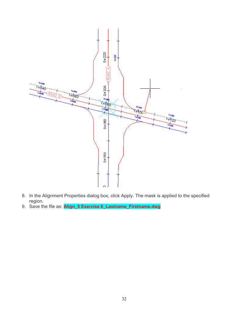
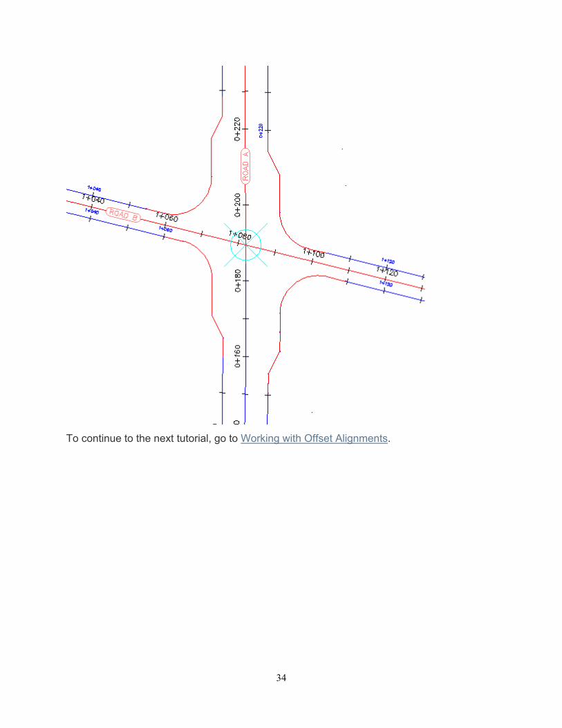
8. In the Alignment Properties dialog box, click Apply. The mask is applied to the specified region.
9. Save the file as: Align_5 Exercise 6_Lastname_Firstname.dwg
33
Further exploration: Apply masks to the west-to-east road offset alignments. (NOT NEEDED)
34
To continue to the next tutorial, go to Working with Offset Alignments.
35
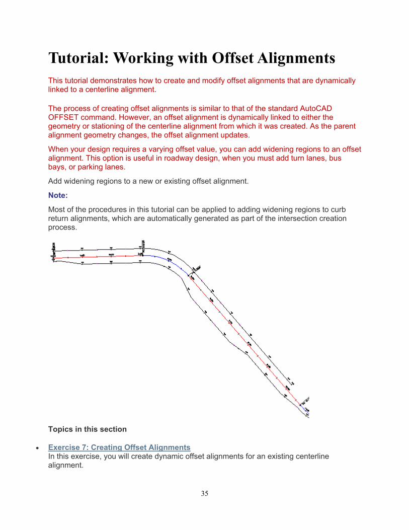
Tutorial: Working with Offset Alignments This tutorial demonstrates how to create and modify offset alignments that are dynamically linked to a centerline alignment.
The process of creating offset alignments is similar to that of the standard AutoCAD OFFSET command. However, an offset alignment is dynamically linked to either the geometry or stationing of the centerline alignment from which it was created. As the parent alignment geometry changes, the offset alignment updates.
When your design requires a varying offset value, you can add widening regions to an offset alignment. This option is useful in roadway design, when you must add turn lanes, bus bays, or parking lanes.
Add widening regions to a new or existing offset alignment.
Note:
Most of the procedures in this tutorial can be applied to adding widening regions to curb return alignments, which are automatically generated as part of the intersection creation process.
Topics in this section
Exercise 7: Creating Offset Alignments In this exercise, you will create dynamic offset alignments for an existing centerline alignment.

36
Exercise 8: Editing an Offset Alignment In this exercise, you will examine the offset alignment editing tools.
Exercise 9: Adding a Widening to an Offset Alignment In this exercise, you will add dynamic widening regions between specified stations of an offset alignment.
Exercise 10: Editing an Offset Widening In this exercise, you will change the transition between an offset alignment and its widening region, and then use grips to modify the widening geometry.
37
Exercise 7: Creating Offset Alignments
In this exercise, you will create dynamic offset alignments for an existing centerline alignment.
Create offsets of a centerline alignment
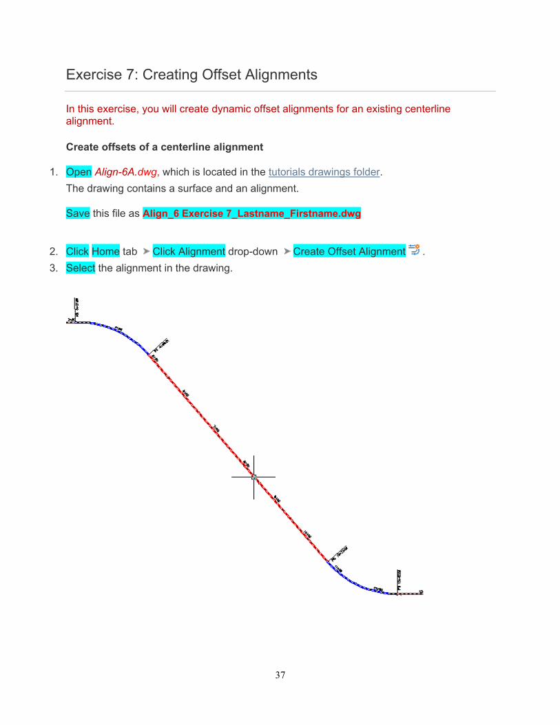
1. Open Align-6A.dwg, which is located in the tutorials drawings folder.
The drawing contains a surface and an alignment.
Save this file as Align_6 Exercise 7_Lastname_Firstname.dwg
2. Click Home tab Click Alignment drop-down Create Offset Alignment .
3. Select the alignment in the drawing.
38
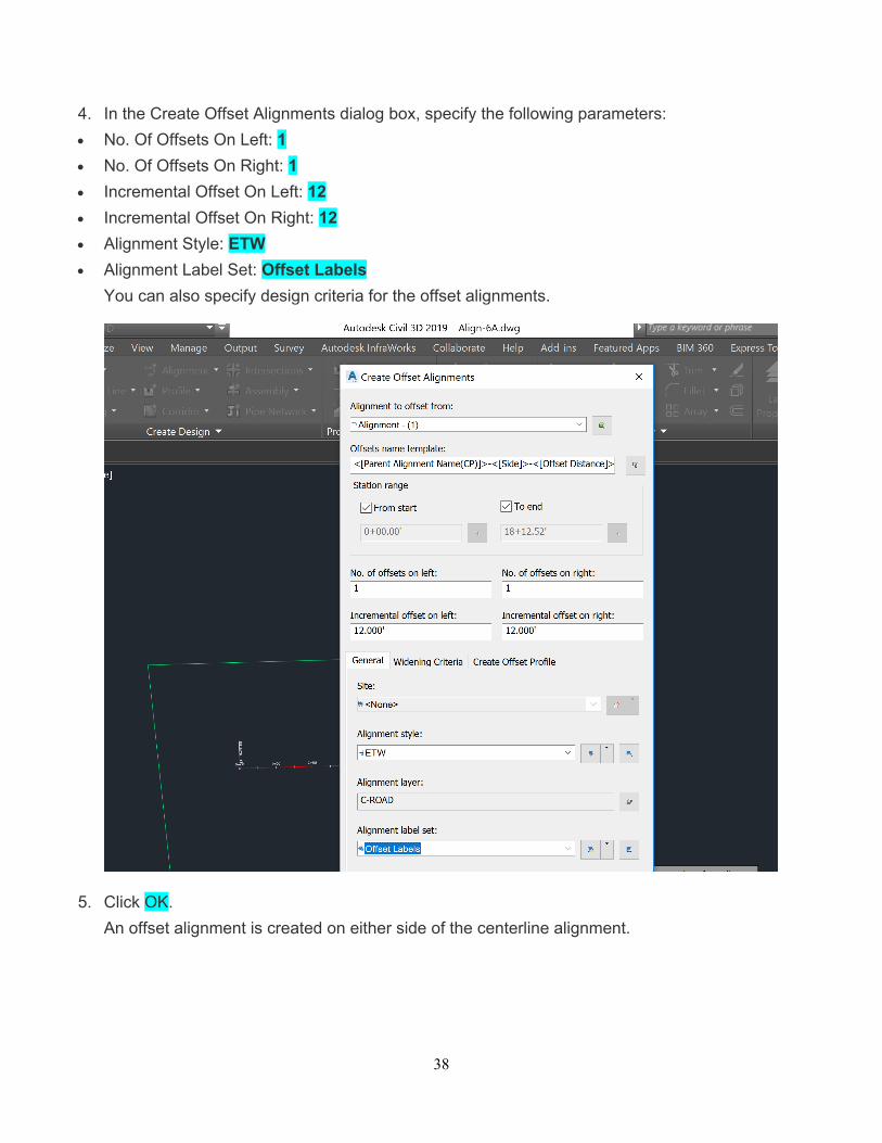
4. In the Create Offset Alignments dialog box, specify the following parameters:
No. Of Offsets On Left: 1
No. Of Offsets On Right: 1
Incremental Offset On Left: 12
Incremental Offset On Right: 12
Alignment Style: ETW
Alignment Label Set: Offset Labels
You can also specify design criteria for the offset alignments.
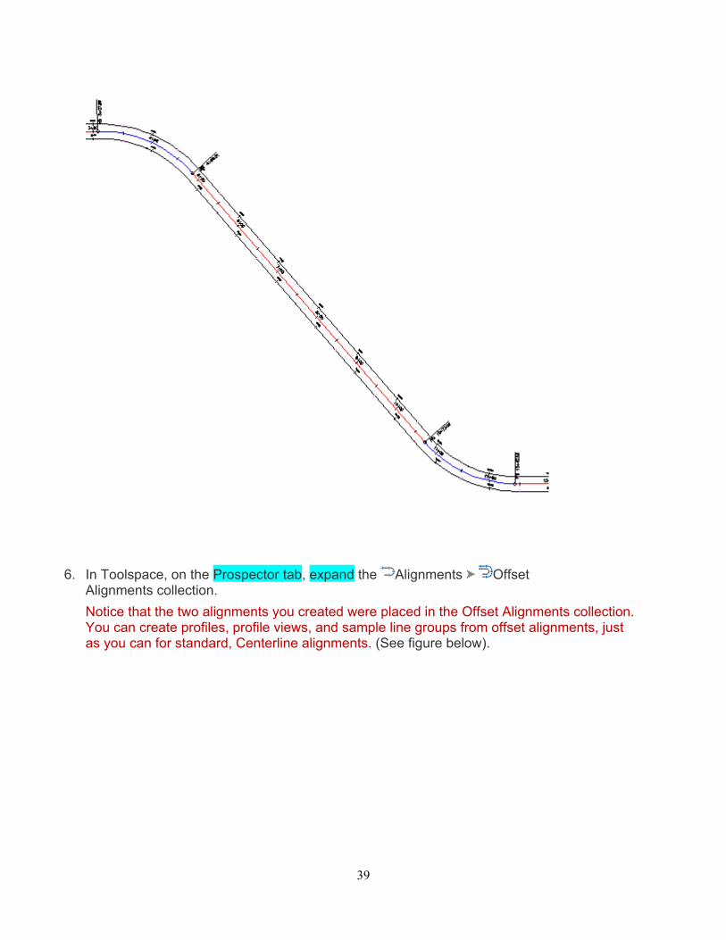
5. Click OK.
An offset alignment is created on either side of the centerline alignment.
39
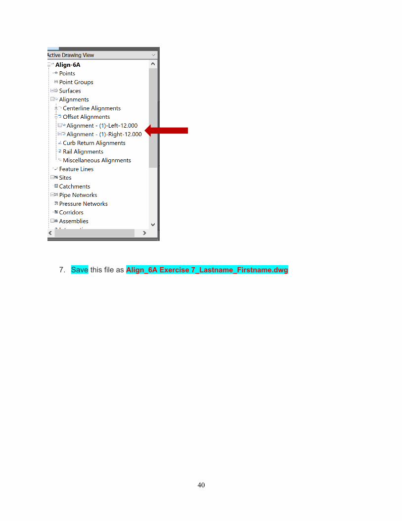
6. In Toolspace, on the Prospector tab, expand the Alignments Offset Alignments collection.
Notice that the two alignments you created were placed in the Offset Alignments collection. You can create profiles, profile views, and sample line groups from offset alignments, just as you can for standard, Centerline alignments. (See figure below).
40
7. Save this file as Align_6A Exercise 7_Lastname_Firstname.dwg
41
Exercise 8: Editing an Offset Alignment
In this exercise, you will examine the offset alignment editing tools.
The geometry editing tools that are available for an offset alignment depend on whether the alignment is static or dynamic. If the offset alignment is dynamically linked to the parent centerline alignment, then you cannot edit the offset alignment geometry. If the offset alignment is static, then you can use the tools on the Alignment Layout Tools toolbar.
An Offset Parameters tab is available in the Alignment Properties dialog box. From this location, you can change parameters such as nominal offset value and start and end stations.
This exercise continues from Exercise 1: Creating Offset Alignments.
Examine the offset alignment geometry
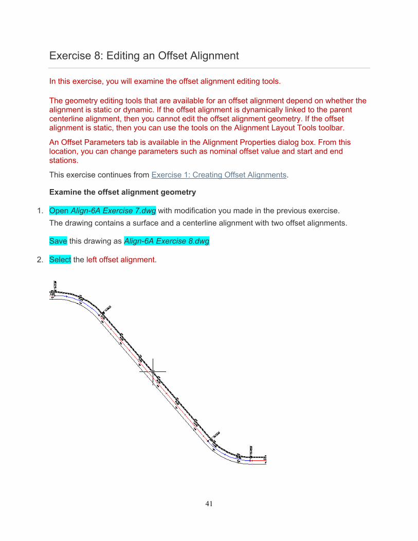
1. Open Align-6A Exercise 7.dwg with modification you made in the previous exercise.
The drawing contains a surface and a centerline alignment with two offset alignments. Save this drawing as Align-6A Exercise 8.dwg
2. Select the left offset alignment.
42
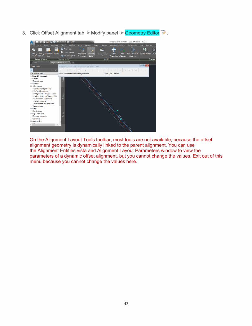
3. Click Offset Alignment tab Modify panel Geometry Editor .
On the Alignment Layout Tools toolbar, most tools are not available, because the offset alignment geometry is dynamically linked to the parent alignment. You can use the Alignment Entities vista and Alignment Layout Parameters window to view the parameters of a dynamic offset alignment, but you cannot change the values. Exit out of this menu because you cannot change the values here.
43
Edit the offset alignment parameters
1. Select the right offset alignment so that the hot grips appear
2. Click Alignment Properties drop-down Alignment Properties .
3. In the Alignment Properties and select the Alignment Properties dialog box, on the Information tab, expand the Type list.
You can change an offset alignment to any of the types in this list. However, if you change the alignment type, the alignment will not be dynamically linked to the centerline alignment. For now, do not make changes in this menu. Select Cancel
4. Next we will edit the width of the offset and change it from 12 to 24 feet. Click the Offset Parameters tab.
You use this tab to refine the offset alignment design. If you do not want the offset alignment to react to changes in the parent alignment geometry, use the Update Mode list to make the alignment static.
Note: The Offset Parameters tab is displayed in the Alignment Properties dialog box only for offset alignments. The dialog box will be blank.
5. Select the Add Widening Button.
6. Specify the following parameters:
Nominal Offset Value: -24.0000
Start Station 0 or 0+00
End Station: 1000 or 10+00
7. Click OK.
The 24-foot offset alignment now ends at station 10+00, and is offset twice as much as the offset alignment on the opposite side of the centerline.
44
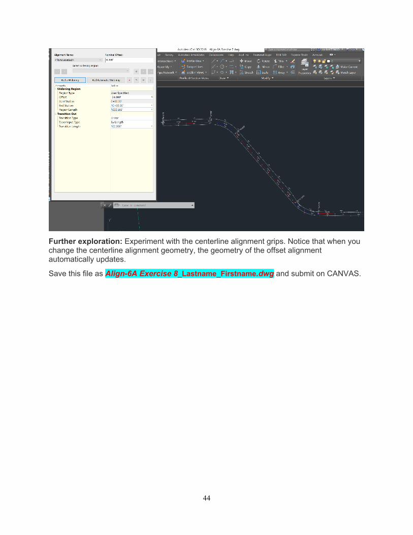
Further exploration: Experiment with the centerline alignment grips. Notice that when you change the centerline alignment geometry, the geometry of the offset alignment automatically updates.
Save this file as Align-6A Exercise 8_Lastname_Firstname.dwg and submit on CANVAS.
45
Exercise 9: Adding a Widening to an Offset Alignment
In this exercise, you will add dynamic widening regions between specified stations of an offset alignment.
Widening regions are useful for creating bus bays, medians, turn lanes, and parking lanes.
This exercise continues from Exercise 2: Editing an Offset Alignment.
Create a widening on an offset alignment
1. This exercise continues with Align-6A Exercise 8.dwg with modification you made in the previous exercise.
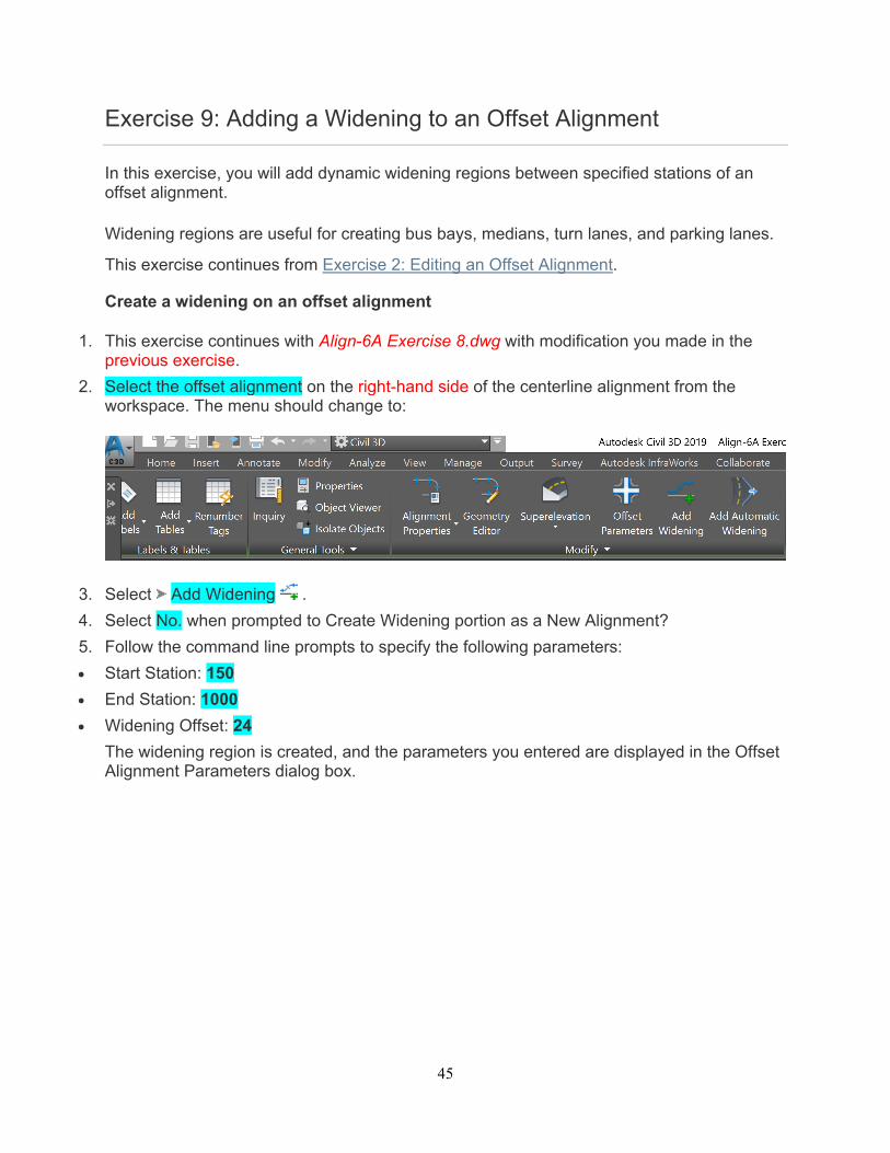
2. Select the offset alignment on the right-hand side of the centerline alignment from the workspace. The menu should change to:
3. Select Add Widening .
4. Select No. when prompted to Create Widening portion as a New Alignment?
5. Follow the command line prompts to specify the following parameters:
Start Station: 150
End Station: 1000
Widening Offset: 24
The widening region is created, and the parameters you entered are displayed in the Offset Alignment Parameters dialog box.
46
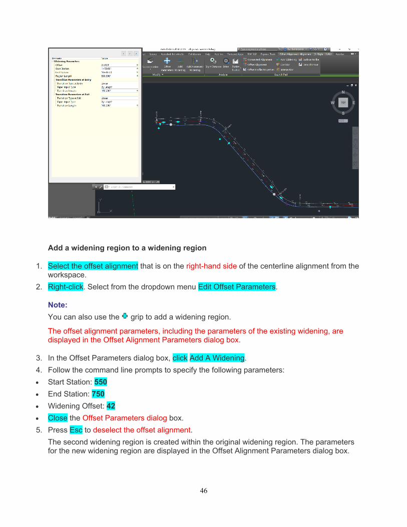
Add a widening region to a widening region
1. Select the offset alignment that is on the right-hand side of the centerline alignment from the workspace.
2. Right-click. Select from the dropdown menu Edit Offset Parameters.
Note:
You can also use the grip to add a widening region.
The offset alignment parameters, including the parameters of the existing widening, are displayed in the Offset Alignment Parameters dialog box.
3. In the Offset Parameters dialog box, click Add A Widening.
4. Follow the command line prompts to specify the following parameters:
Start Station: 550
End Station: 750
Widening Offset: 42
Close the Offset Parameters dialog box.
5. Press Esc to deselect the offset alignment.
The second widening region is created within the original widening region. The parameters for the new widening region are displayed in the Offset Alignment Parameters dialog box.
47
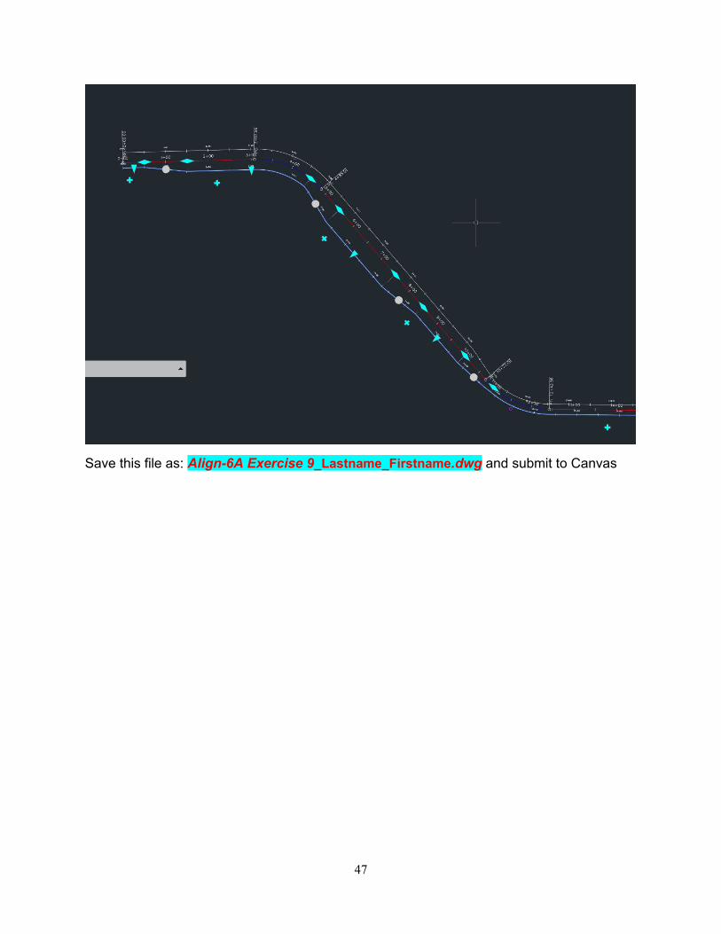
Save this file as: Align-6A Exercise 9_Lastname_Firstname.dwg and submit to Canvas
48
Exercise 10: Editing an Offset Widening
In this exercise, you will change the transition between an offset alignment and its widening region, and then use grips to modify the widening geometry.
Change the widening transition
1. Open Align-6A Exercise9.dwg. Save As this file Align-6A Exercise10.dwg
The drawing contains a surface and a centerline alignment with two offset alignments. The offset alignment on the right-hand side of the centerline alignment has two widening regions.
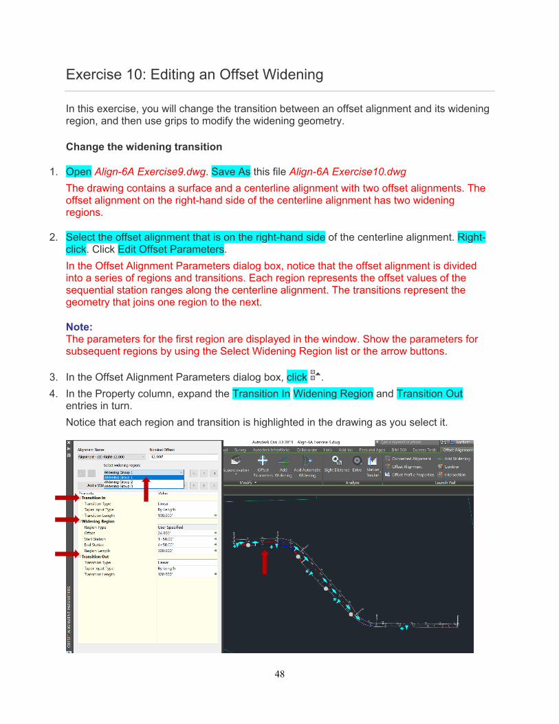
2. Select the offset alignment that is on the right-hand side of the centerline alignment. Right-click. Click Edit Offset Parameters.
In the Offset Alignment Parameters dialog box, notice that the offset alignment is divided into a series of regions and transitions. Each region represents the offset values of the sequential station ranges along the centerline alignment. The transitions represent the geometry that joins one region to the next.
Note: The parameters for the first region are displayed in the window. Show the parameters for subsequent regions by using the Select Widening Region list or the arrow buttons.
3. In the Offset Alignment Parameters dialog box, click .
4. In the Property column, expand the Transition In Widening Region and Transition Out entries in turn.
Notice that each region and transition is highlighted in the drawing as you select it.
49
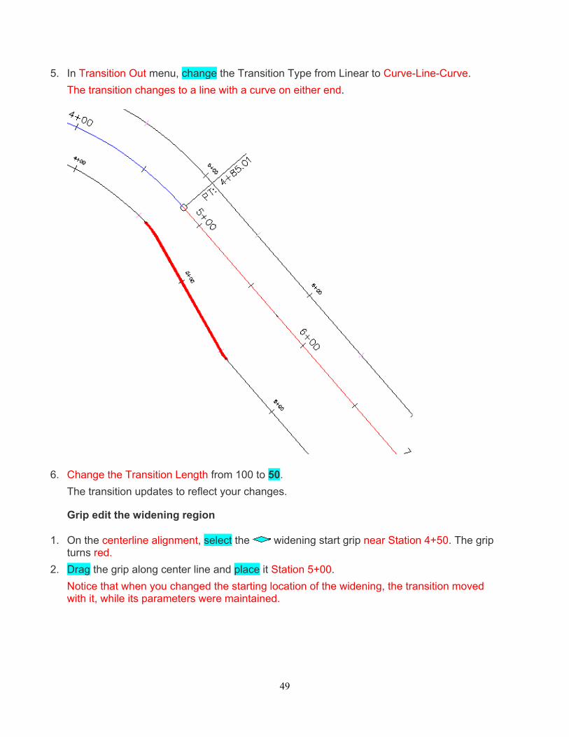
5. In Transition Out menu, change the Transition Type from Linear to Curve-Line-Curve.
The transition changes to a line with a curve on either end.
6. Change the Transition Length from 100 to 50.
The transition updates to reflect your changes.
Grip edit the widening region
1. On the centerline alignment, select the widening start grip near Station 4+50. The grip turns red.
2. Drag the grip along center line and place it Station 5+00.
Notice that when you changed the starting location of the widening, the transition moved with it, while its parameters were maintained.
50
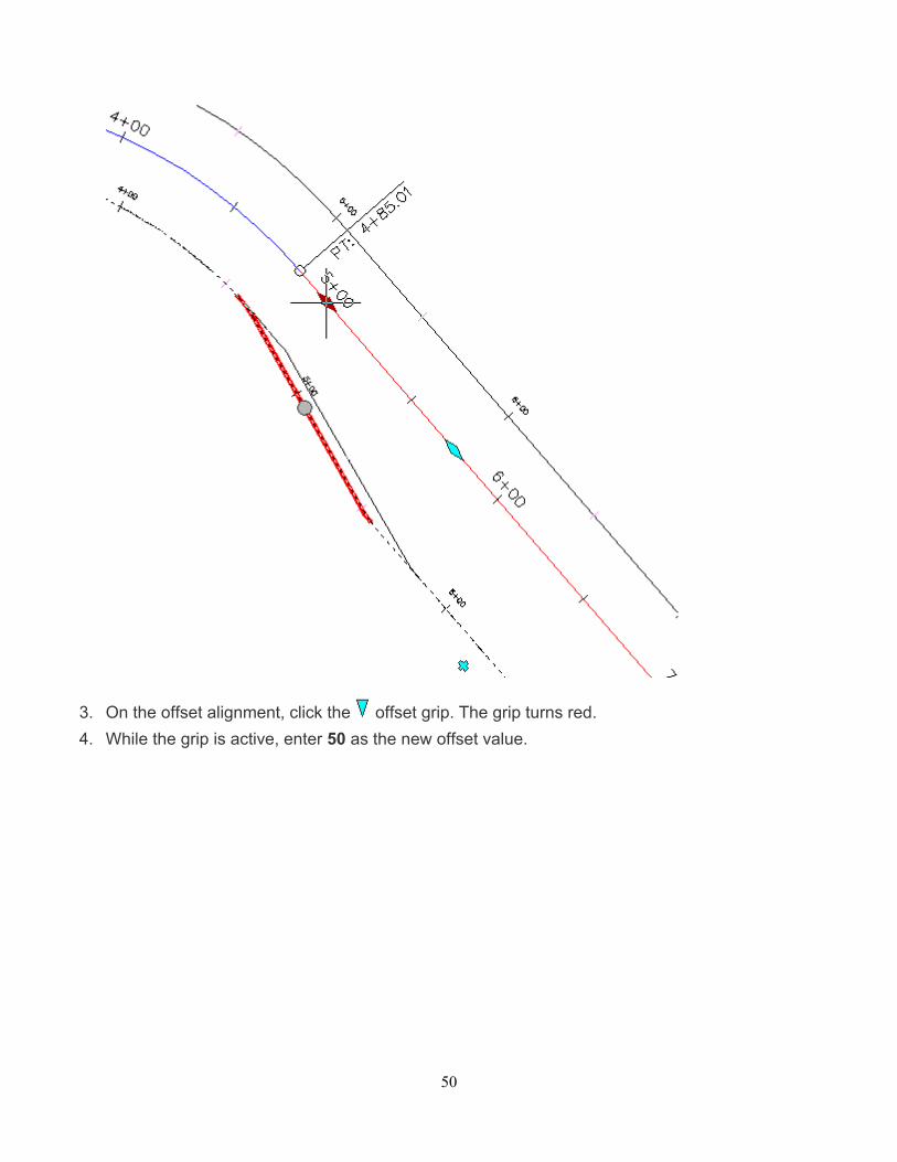
3. On the offset alignment, click the offset grip. The grip turns red.
4. While the grip is active, enter 50 as the new offset value.
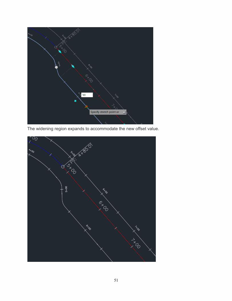
51
The widening region expands to accommodate the new offset value.
52
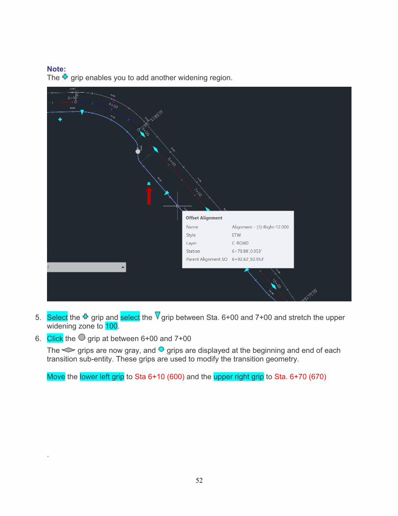
Note: The grip enables you to add another widening region.
5. Select the grip and select the grip between Sta. 6+00 and 7+00 and stretch the upper widening zone to 100.
6. Click the grip at between 6+00 and 7+00
The grips are now gray, and grips are displayed at the beginning and end of each transition sub-entity. These grips are used to modify the transition geometry.
Move the lower left grip to Sta 6+10 (600) and the upper right grip to Sta. 6+70 (670) .
53
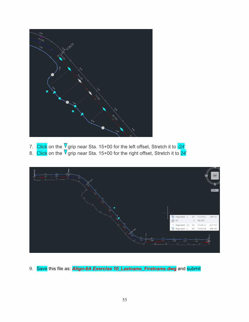
7. Click on the grip near Sta. 15+00 for the left offset, Stretch it to -24’ 8. Click on the grip near Sta. 15+00 for the right offset, Stretch it to 24’
9. Save this file as: Align-6A Exercise 10_Lastname_Firstname.dwg and submit
54
OPTIONAL Tutorial: Designing an Alignment that Refers to Local Standards This tutorial demonstrates how to validate that your alignment design meets criteria specified by a local agency.
To create an alignment using design criteria, you use the same basic workflow that you use to create an alignment without design criteria. During alignment creation, you can select a design criteria file, from which you can specify the superelevation attainment method and minimum radius and transition (spiral) length tables. Design criteria files that contain AASHTO design standards are included with AutoCAD Civil 3D. If your local design standards differ from the AASHTO standards, you can create a custom design criteria file using the Design Criteria Editor dialog box.
Some alignment design criteria is not available in table form in the design criteria file. For these criteria, you can define design checks to validate design standards. To apply a design check to an alignment, you must add it to a design check set.
If the design parameters for a sub-entity violate a design check or the minimum values established in the design criteria file, a warning symbol appears on the sub-entity in the drawing window, and next to the violated value in the Alignment Entities vista and Alignment Layout Parameters dialog box. When you hover the cursor over a warning symbol, a tooltip displays the standard that has been violated. The display of the warning symbol is controlled by the alignment style.
Note:
You can also use the Design Criteria tab on the Alignment Properties dialog box to apply design criteria to an alignment after it has been created.
Topics in this section
Exercise 1: Drawing an Alignment that Refers to Design Criteria In this exercise, you will use the criteria-based design tools to create an alignment that complies with specified standards.
Exercise 2: Viewing and Correcting Alignment Design Criteria Violations In this exercise, you will examine alignment design criteria violations, and then learn how to correct a criteria violation.
Exercise 3: Working with Design Checks In this exercise, you will create an alignment design check, add the design check to a design check set, and then apply the design check set to an alignment.
Exercise 4: Modifying a Design Criteria File In this exercise, you will add a radius and speed table to the design criteria file.
55
Exercise 1: Drawing an Alignment that Refers to Design Criteria
In this exercise, you will use the criteria-based design tools to create an alignment that complies with specified standards.
This exercise is divided into two parts:
First, you will specify design criteria for an alignment as you create it, and then draw a series of alignment entities that violate the design criteria. You will correct the violations in Exercise 2: Checking the Alignment Design for Criteria Violations.
Second, you will create an alignment entity that meets the design criteria specified in the design criteria file. You will use the minimum default values that are displayed on the command line to ensure that the entity meets the specified design criteria.
Note: AutoCAD Civil 3D can also validate that alignment entities are tangent to one another.
Specify design criteria for an alignment
1. Open Align-7A.dwg, which is located in the tutorials drawings folder.
The drawing contains a surface marked with several circles, labeled A through E.
Note: Ensure that Object Snap (OSNAP) is turned on. For more information, see Object Snapping.
2. Click Home tab Create Design panel Alignment drop-down Alignment Creation Tools .
3. In the Create Alignment – Layout dialog box, accept the default values for Name and Starting Station. Leave the Description field blank for this exercise.
4. On the General tab, specify the following parameters:
Site: <None>
Alignment Style: Design Style
Alignment Layer: C-ROAD
Alignment Label Set: Major Minor and Geometry Points
5. On the Design Criteria tab, for Starting Design Speed, enter 50 km/h.
This speed will be applied to the starting station of the alignment. You can add design speeds as needed to other stations. A design speed is applied to all subsequent stations until either the next station that has an assigned design speed or the alignment ending station.
6. Select the Use Criteria-Based Design check box.
When this option is selected, the criteria-based design tools are available. There are two check boxes that are selected by default:
56
Use Design Criteria File —The design criteria file is an XML file that contains minimum design standards for alignment and profile objects. The design criteria file can be customized to support local design standards for design speed, superelevation, and minimum speed, radius, and length of individual entities. The Default Criteria table lists the properties that are included in the default design criteria file, the location of which is displayed in the field above the Default Criteria table.
You will learn more about the design criteria file in Exercise 3: Modifying a Design Criteria File for Alignments.
Use Design Check Set —Design checks are user-defined formulas that verify alignment and profile parameters that are not contained in the design criteria file. Design checks must be included in a design check set, which is applied to an alignment or profile.
7. In the Use Design Criteria File area, click .
8. In the Select Design Speed Table dialog box, select _Autodesk Civil 3D Metric Roadway Design Standards.xml. Click Open.
For this exercise, you will use AASHTO 2001 standards, which are included in the provided design criteria files. You will learn about creating a custom design criteria file in Exercise 4: Modifying a Design Criteria File.
9. In the Default Criteria table, in the Minimum Radius Table row, change the Value to AASHTO 2001 eMax 6%.
10. In the Use Design Check Set list, select 50kmh Roadway Length Checks. Click OK.
This design check set contains a simple design check. You will create another design check and add it to this design check set in Exercise 3: Working with Design Checks.
Draw alignment entities that meet the specified design criteria
1. On the Alignment Layout Tools toolbar, click Tangent-Tangent (No Curves).
2. Snap to the center of Circle A to specify a start point for the alignment. Stretch a line out, and specify additional PIs by snapping to the center of Circles B, C, and D (in order). Then, right-click to end the horizontal alignment layout command.
3. On the Alignment Layout Tools toolbar, click Free Spiral-Curve-Spiral (Between Two Entities).
4. As prompted on the command line, click the tangent entity that enters Circle B from the left (the ‘first entity’).
5. Click the tangent that exits Circle B on the right (the ‘next entity’).
6. Press Enter to accept the default value of a curve solution angle that is less than 180 degrees.
7. For radius, enter 75.
Notice that the Specify Radius prompt includes a default value. This value is the minimum acceptable curve radius at the current design speed. The minimum value is contained in the Minimum Radius Table in the design criteria file. You can enter a different value, as long
57
as it is greater than the default minimum value that is displayed. For this exercise, you will use values that do not meet the design criteria, and then examine the results.
8. For spiral in length, enter 25.
9. For spiral out length, enter 25.
10. In the Alignment Layout Tools toolbar, click the drop-down list . Click Free Curve Fillet (Between Two Entities, Radius).
11. As prompted on the command line, click the tangent that enters Circle C from the left (the ‘first entity’).
12. Click the tangent that exits from Circle C on the right (the ‘next entity’).
13. Press Enter to select the default value of a curve less than 180 degrees.
14. Press Enter to select the minimum radius of 90.000m.
15. Right-click to end the command.
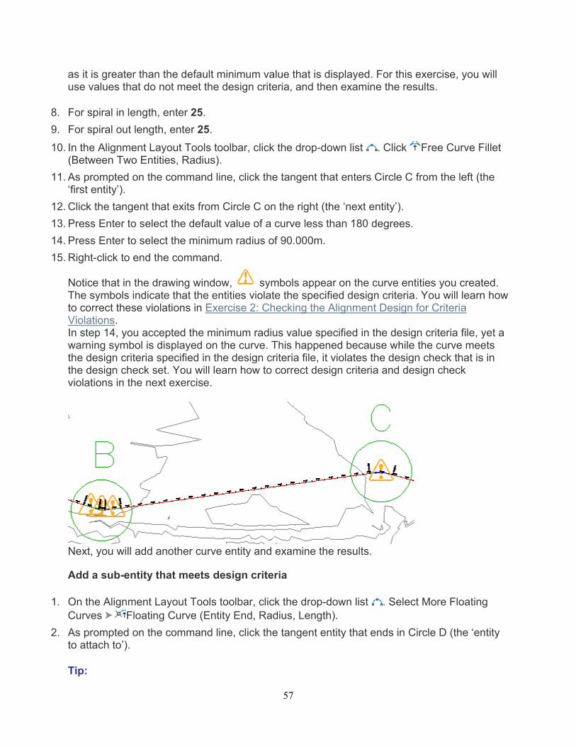
Notice that in the drawing window, symbols appear on the curve entities you created. The symbols indicate that the entities violate the specified design criteria. You will learn how to correct these violations in Exercise 2: Checking the Alignment Design for Criteria Violations. In step 14, you accepted the minimum radius value specified in the design criteria file, yet a warning symbol is displayed on the curve. This happened because while the curve meets the design criteria specified in the design criteria file, it violates the design check that is in the design check set. You will learn how to correct design criteria and design check violations in the next exercise.
Next, you will add another curve entity and examine the results.
Add a sub-entity that meets design criteria
1. On the Alignment Layout Tools toolbar, click the drop-down list . Select More Floating Curves Floating Curve (Entity End, Radius, Length).
2. As prompted on the command line, click the tangent entity that ends in Circle D (the ‘entity to attach to’).
Tip:
58
The warning symbols do not automatically scale when you zoom in. Enter REGEN on the command line to resize the warning symbols.
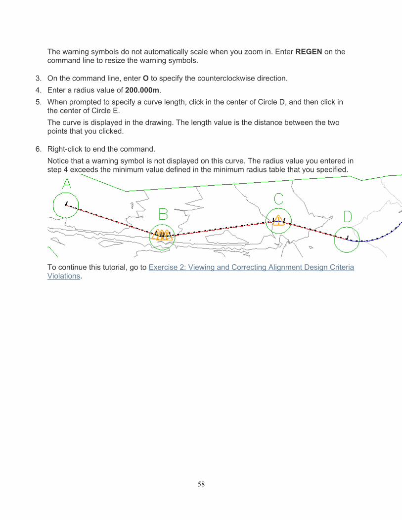
3. On the command line, enter O to specify the counterclockwise direction.
4. Enter a radius value of 200.000m.
5. When prompted to specify a curve length, click in the center of Circle D, and then click in the center of Circle E.
The curve is displayed in the drawing. The length value is the distance between the two points that you clicked.
6. Right-click to end the command.
Notice that a warning symbol is not displayed on this curve. The radius value you entered in step 4 exceeds the minimum value defined in the minimum radius table that you specified.
To continue this tutorial, go to Exercise 2: Viewing and Correcting Alignment Design Criteria Violations.
59
Exercise 2: Viewing and Correcting Alignment Design Criteria Violations
In this exercise, you will examine alignment design criteria violations, and then learn how to correct a criteria violation.
When a sub-entity violates either a criteria or design check, a warning symbol is displayed on the sub-entity in the drawing window, Alignment Entities vista, and Alignment Layout Parameters dialog box. When the cursor is hovered over a warning symbol in the drawing window, a tooltip displays information about the violation. If a design criteria has been violated, the tooltip displays the criteria that has been violated, as well as the minimum value required to meet the criteria. If a design check has been violated, the tooltip displays the name of the design check that has been violated.
This exercise continues from Exercise 1: Creating an Alignment Using Design Criteria.
Check the alignment design for criteria violations
This exercise continues with Align-7A.dwg with modification you made in the previous exercise.
1. Pan and zoom until you can see Circles B and C on the surface.
Tip:
The warning symbols do not automatically scale when you zoom in. Enter REGEN on the command line to resize the warning symbols.
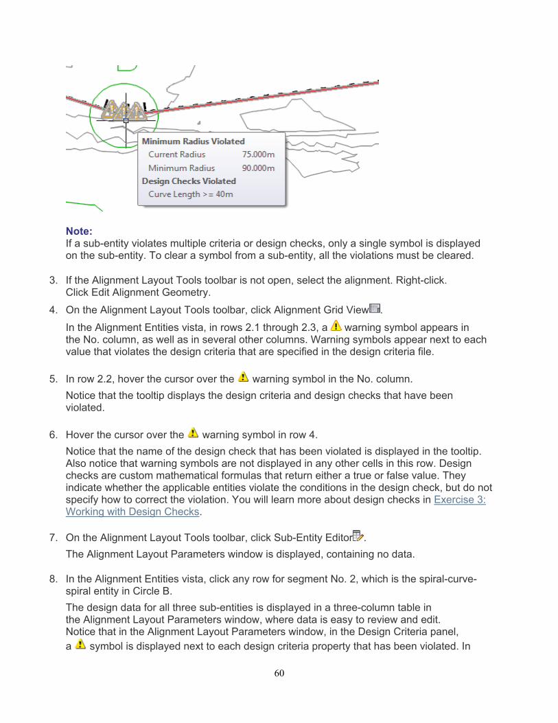
2. Hover the cursor over the middle symbol in Circle B.
The tooltips are a convenient way to review design criteria violations in the drawing window. Two violations are displayed in the tooltip:
First, the curve does not meet the recommended minimum radius. The curve radius and minimum acceptable parameter values are both displayed.
Second, the curve violates a design check that has been applied to the alignment. Notice that the name of the design check is displayed, but not the current or recommended values. Values are not displayed because design checks are custom formulas that are created by the user.
60
Note: If a sub-entity violates multiple criteria or design checks, only a single symbol is displayed on the sub-entity. To clear a symbol from a sub-entity, all the violations must be cleared.
3. If the Alignment Layout Tools toolbar is not open, select the alignment. Right-click. Click Edit Alignment Geometry.
4. On the Alignment Layout Tools toolbar, click Alignment Grid View .
In the Alignment Entities vista, in rows 2.1 through 2.3, a warning symbol appears in the No. column, as well as in several other columns. Warning symbols appear next to each value that violates the design criteria that are specified in the design criteria file.
5. In row 2.2, hover the cursor over the warning symbol in the No. column.
Notice that the tooltip displays the design criteria and design checks that have been violated.
6. Hover the cursor over the warning symbol in row 4.
Notice that the name of the design check that has been violated is displayed in the tooltip. Also notice that warning symbols are not displayed in any other cells in this row. Design checks are custom mathematical formulas that return either a true or false value. They indicate whether the applicable entities violate the conditions in the design check, but do not specify how to correct the violation. You will learn more about design checks in Exercise 3: Working with Design Checks.
7. On the Alignment Layout Tools toolbar, click Sub-Entity Editor .
The Alignment Layout Parameters window is displayed, containing no data.
8. In the Alignment Entities vista, click any row for segment No. 2, which is the spiral-curve-spiral entity in Circle B.
The design data for all three sub-entities is displayed in a three-column table in the Alignment Layout Parameters window, where data is easy to review and edit. Notice that in the Alignment Layout Parameters window, in the Design Criteria panel, a symbol is displayed next to each design criteria property that has been violated. In
61
the Layout Parameters panel, the Value column displays the actual parameters of each sub-entity. The Constraints column displays the design criteria values that the sub-entities must meet. A symbol is displayed next to each parameter that violates the design criteria. As is true in the drawing window and Alignment Entities Vista, the design check that has been violated is displayed, but individual parameters that violate the check are not marked.
Correct design criteria violations
1. In the Alignment Layout Parameters window, on the Layout Parameters panel, change the Spiral In Length Value to 33.000m. Press Enter.
Notice that the warning symbol is cleared from the Spiral In Length row.
2. Change the Spiral Out Length Value to 33.000m. Press Enter.
3. Change the Curve RadiusValue to 100.000m. Press Enter.
The warning symbol is cleared from the Curve Radius row, as well as from the Alignment Entities vista. Notice that the warning symbol is still displayed on all the curve sub-entity. The curve still violates the design check. To clear the warning symbols, all sub-entities in the group must meet the values specified in both the design criteria file and the applicable design checks.
4. In the Alignment Entities vista, in row 2.2, examine the Length column.
Notice that the Length value is less than the value of 40 that is specified by the design check. Notice that you cannot edit the Length value for this type of curve. However, you can increase the curve radius to increase the curve length.
5. In row 2.2, change the Radius value to 200.000m. Press Enter.
6. In the Alignment Entities vista, select row 4. In the Length column, change the value to 40.000m. Press Enter.
To continue this tutorial, go to Exercise 3: Working with Design Checks.
62
Exercise 3: Working with Design Checks
In this exercise, you will create an alignment design check, add the design check to a design check set, and then apply the design check set to an alignment.
To create a design check, you set up a mathematical formula, using existing alignment sub-entity properties. The complexity of design check formulas can vary greatly. In this exercise, you will create a relatively simple design check that validates whether the tangent length meets a minimum value at a given design speed.
Note:
The processes for creating design checks for alignments and profiles are very similar. The basic workflow that is demonstrated in this exercise can be used for both alignment and profile design checks.
This exercise continues from Exercise 2: Viewing and Correcting Alignment Design Criteria Violations.
Create an alignment design check
This exercise continues with Align-7A.dwg with modification you made in the previous exercise.
1. In Toolspace, on the Settings tab, expand the Alignment Design Checks collection.
Notice that five collections are available. The Design Check Sets collection contains combinations of design checks. A design check must be added to a design check set before it can be applied to an alignment. The other four collections contain the design checks for each type of alignment entity. Each entity type has specific properties that can be checked. When you create a design check set, you specify the type of entity you want to check, and then the specific design check you want to apply to that entity. You can apply multiple design checks to each entity type.
Note: The Tangent Intersection collection contains design checks for spiral and curve groups.
2. Right-click the Line collection. Click New.
3. In the New Design Check dialog box, for Name, enter 310m @ 50km/h.
BestPractice:
Because design check tooltips do not display specific values, a design check name should be specific and unique. Use the mathematical formula or other specific information to simplify the process of correcting a design check violation.
4. For Description, enter Tangent length must be >= 310m if design speed is >= 50km/h.
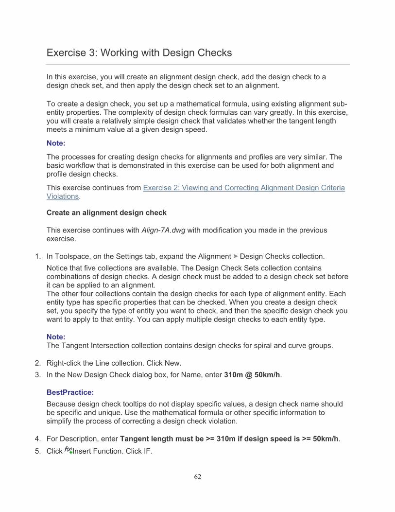
5. Click Insert Function. Click IF.
63
The IF function is displayed in the Design Check field.
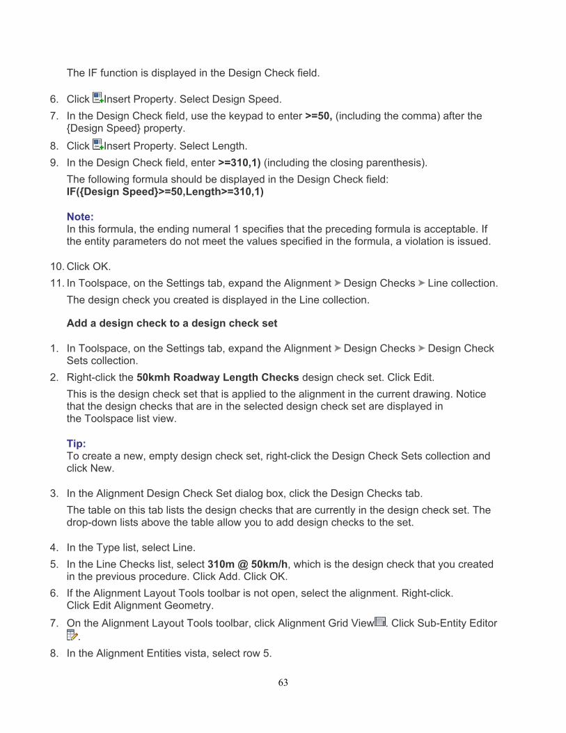
6. Click Insert Property. Select Design Speed.
7. In the Design Check field, use the keypad to enter >=50, (including the comma) after the {Design Speed} property.
8. Click Insert Property. Select Length.
9. In the Design Check field, enter >=310,1) (including the closing parenthesis).
The following formula should be displayed in the Design Check field: IF({Design Speed}>=50,Length>=310,1)
Note: In this formula, the ending numeral 1 specifies that the preceding formula is acceptable. If the entity parameters do not meet the values specified in the formula, a violation is issued.
10. Click OK.
11. In Toolspace, on the Settings tab, expand the Alignment Design Checks Line collection.
The design check you created is displayed in the Line collection.
Add a design check to a design check set
1. In Toolspace, on the Settings tab, expand the Alignment Design Checks Design Check Sets collection.
2. Right-click the 50kmh Roadway Length Checks design check set. Click Edit.
This is the design check set that is applied to the alignment in the current drawing. Notice that the design checks that are in the selected design check set are displayed in the Toolspace list view.
Tip: To create a new, empty design check set, right-click the Design Check Sets collection and click New.
3. In the Alignment Design Check Set dialog box, click the Design Checks tab.
The table on this tab lists the design checks that are currently in the design check set. The drop-down lists above the table allow you to add design checks to the set.
4. In the Type list, select Line.
5. In the Line Checks list, select 310m @ 50km/h, which is the design check that you created in the previous procedure. Click Add. Click OK.
6. If the Alignment Layout Tools toolbar is not open, select the alignment. Right-click. Click Edit Alignment Geometry.
7. On the Alignment Layout Tools toolbar, click Alignment Grid View . Click Sub-Entity Editor.
8. In the Alignment Entities vista, select row 5.

64
9. In the Alignment Layout Parameters dialog box, examine the Length value.
In the Design Checks panel, notice that a warning symbol is displayed next to the310m @ 50km/h design check you created. In the Layout Parameters panel, notice that the Length value is less than the 310 meters specified by the design check.
Further exploration: Increase the length of the line until it meets or exceeds 310 meters. This is a fixed line that was created using the Tangent-Tangent (No Curves) command, so you must move the endpoint grip inside Circle D to increase the length.
To continue this tutorial, go to Exercise 4: Modifying a Design Criteria File.
65
Exercise 4: Modifying a Design Criteria File
In this exercise, you will add a radius and speed table to the design criteria file.
If your local agency standards differ from the standards in the supplied design criteria file, you can use the Design Criteria Editor dialog box to customize the file to support your local standards.
In this exercise, you will add a minimum radius table to an existing design criteria file, and then save the file under a new name.
This exercise continues from Exercise 3: Working with Design Checks.
Add a minimum radius table
This exercise continues with Align-7A.dwg with modification you made in the previous exercise.
1. In the drawing, select the alignment.
2. Click Alignment tab Modify panel Design Criteria Editor .
When the Design Criteria Editor dialog box opens, it displays the design criteria for the default design criteria file. The folders on the left side of the dialog box contain tables that specify the units of measure used in the design criteria file, and design criteria tables for alignments and profiles. You can use this dialog box to modify the criteria in the current file, open another file, or create a new file. In the following steps, you will add a criteria table to an existing file, and then save the changes as a new file.
3. On the left side of the dialog box, expand the Alignments Minimum Radius Tables collection.
The collection contains several minimum radius tables.
4. Right-click Minimum Radius Tables. Click New Minimum Radius Table.
An empty table appears at the end of the Minimum Radius Tables collection.
5. Replace the New Minimum Radius Table text with Local Standards eMax 7%. Press Enter.
Save the design criteria file
1. Click Save As.
2. In the Enter A File Name To Save dialog box, navigate to the My Civil 3D Tutorial Data folder. In the File Name field, enter Sample_Local_Criteria.xml. Click Save.
If a design criteria file must be shared by multiple users, it must be saved in a location to which all applicable users have access. If you send a drawing that uses a custom design criteria file to a user that does not have access to the shared location, then you also must send the design criteria file.
66
Tip: When the Use Design Criteria File option is selected during alignment creation, the first design criteria found in the Data\Corridor Design Standards\[units] folder is applied to an alignment by default. To ensure that a custom design criteria file is selected by default, make sure that its name places it first in the directory.
Add criteria to a table
1. In the Design Criteria File Editor dialog box, on the left-hand side, ensure that the Local Standards eMax 7% table is selected.
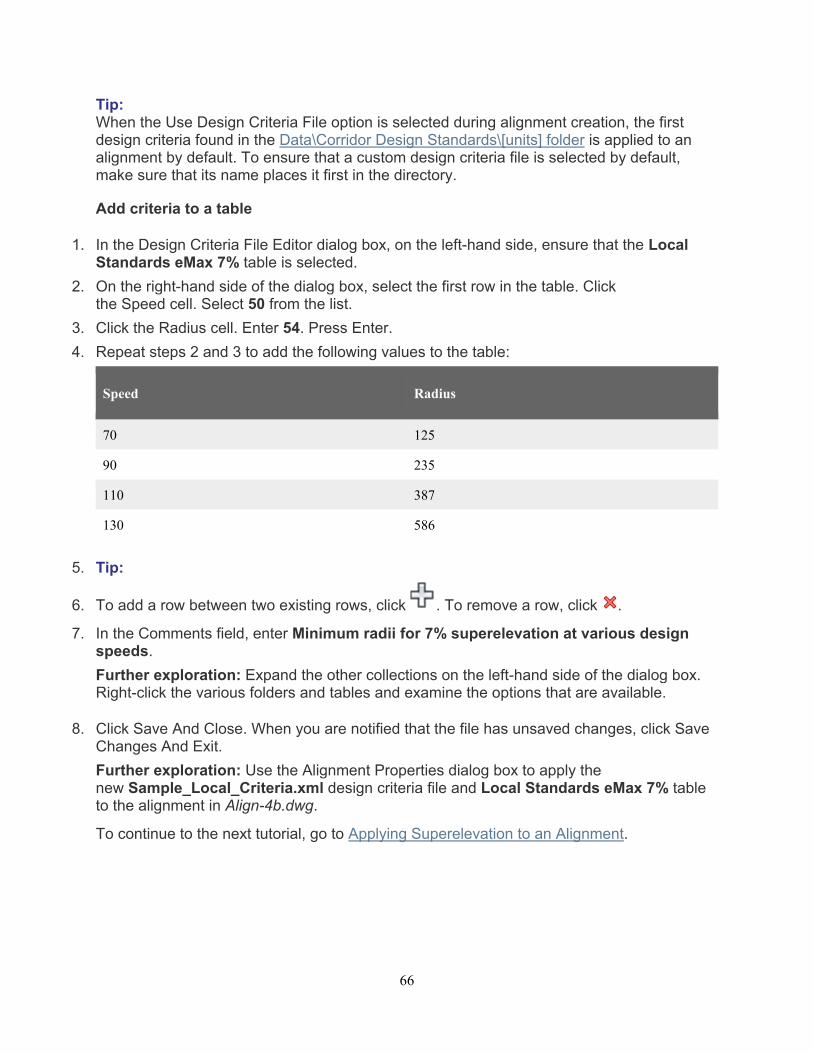
2. On the right-hand side of the dialog box, select the first row in the table. Click the Speed cell. Select 50 from the list.
3. Click the Radius cell. Enter 54. Press Enter.
4. Repeat steps 2 and 3 to add the following values to the table:
Speed Radius
70 125
90 235
110 387
130 586
5. Tip:
6. To add a row between two existing rows, click . To remove a row, click .
7. In the Comments field, enter Minimum radii for 7% superelevation at various design speeds.
Further exploration: Expand the other collections on the left-hand side of the dialog box. Right-click the various folders and tables and examine the options that are available.
8. Click Save And Close. When you are notified that the file has unsaved changes, click Save Changes And Exit.
Further exploration: Use the Alignment Properties dialog box to apply the new Sample_Local_Criteria.xml design criteria file and Local Standards eMax 7% table to the alignment in Align-4b.dwg.
To continue to the next tutorial, go to Applying Superelevation to an Alignment.
67
Optional Tutorial: Applying Superelevation to an Alignment In this tutorial, you will calculate superelevation for alignment curves, create a superelevation view to display the superelevation data, and edit the superelevation data both graphically and in a tabular format.
The superelevation feature enables you to apply your local roadway design standards to automatically calculate roadway cross slopes around curves.
Best Practice:
Superelevation should be calculated before the corridor model is built along the alignment.
Topics in this section
Exercise 1: Calculating Superelevation for an Alignment In this exercise, you will calculate superelevation for all the curves in an alignment.
Exercise 2: Calculating Superelevation for an Individual Curve In this exercise, you will calculate superelevation for a single curve in an alignment that already has superelevation data calculated for other curves.
Exercise 3: Creating a Superelevation View In this exercise, you will display superelevation data in a graph, which you can use to graphically edit superelevation data.
Exercise 4: Adding and Modifying Superelevation Stations In this exercise, you will resolve overlap between two superelevated curves by adding and removing critical stations, and then editing existing superelevation data.
Exercise 5: Editing Superelevation Parameters Graphically In this exercise, you will use grips in a superelevation view to modify the superelevation cross slopes and critical station values.
68
Exercise 1: Calculating Superelevation for an Alignment
In this exercise, you will calculate superelevation for all the curves in an alignment.
To calculate superelevation for a curve
1. Open Align-Superelevation-1.dwg, which is located in the tutorials drawings folder.
2. Select the alignment.
3. Click Alignment tab Modify panel Superelevation drop-down Calculate/Edit Superelevation .
A dialog box indicates that the alignment does not contain superelevation data.
4. Click Calculate Superelevation Now.
In the Create Superelevation dialog box, the Roadway Type page contains options for how to apply superelevation to various types of roadways. Conceptual graphics illustrate the point about which each lane will pivot.
5. Select Undivided Crowned.
6. In the Pivot Method list, select Center Baseline.
7. Click Next.
The Lanes page contains specifications for the number, width, and slope of each lane.
8. Specify the following parameters:
Symmetric Roadway: Selected
This specifies that the same parameters are used for both sides.
Number of Lanes Right: 1
Normal Lane Width: 6.000m
Normal Lane Slope: -2.00%
9. Click Next.
The Shoulder Control page contains specifications for how the roadway shoulders behave when the lanes are superelevated.
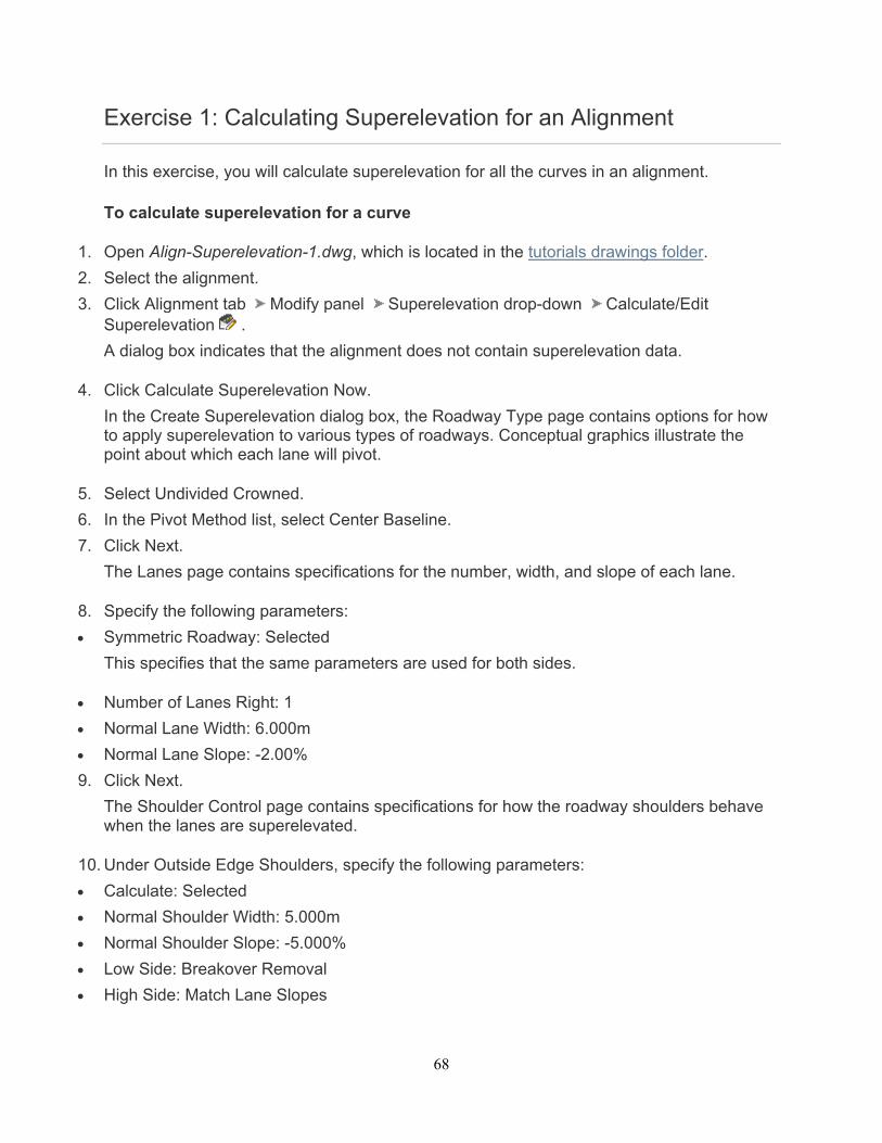
10. Under Outside Edge Shoulders, specify the following parameters:
Calculate: Selected
Normal Shoulder Width: 5.000m
Normal Shoulder Slope: -5.000%
Low Side: Breakover Removal
High Side: Match Lane Slopes
69
Note: The Inside Median Shoulder options are disabled because you selected an undivided roadway type on the Roadway Type page.
11. Click Next.
The Attainment page enables you to specify the superelevation standards to apply. You apply standards by selecting them from a series of lists. The content of the lists reflects the content of the currently selected design criteria file, which you can customize to suit your local standards. For more information, see the Modifying a Design Criteria File tutorial exercise.
12. Specify the following parameters:
Design Criteria File: _Autodesk Civil 3D Metric Roadway Design Standards.xml, which is located in the Data folder in Corridor Design Standards/Metric
This is the same design criteria file that the criteria-based design feature uses to validate the alignment and profile geometry.
Superelevation Rate Table: AASHTO 2001 eMax 6%
Transition Length Table: 2 Lane
Attainment Method: AASHTO 2001 Crowned Roadway
% Transition Into Tangent: 70.00%
% Transition Into Spiral: 100.00%
Apply Curve Smoothing: Cleared
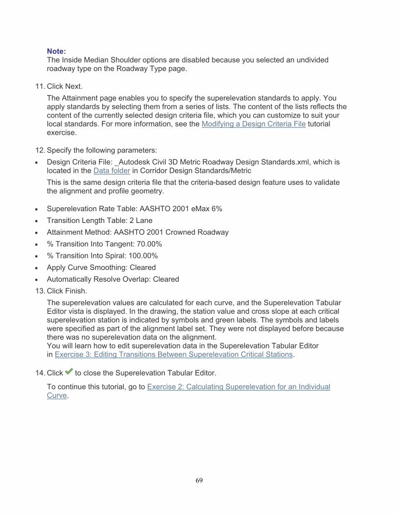
Automatically Resolve Overlap: Cleared
13. Click Finish.
The superelevation values are calculated for each curve, and the Superelevation Tabular Editor vista is displayed. In the drawing, the station value and cross slope at each critical superelevation station is indicated by symbols and green labels. The symbols and labels were specified as part of the alignment label set. They were not displayed before because there was no superelevation data on the alignment. You will learn how to edit superelevation data in the Superelevation Tabular Editor in Exercise 3: Editing Transitions Between Superelevation Critical Stations.
14. Click to close the Superelevation Tabular Editor.
To continue this tutorial, go to Exercise 2: Calculating Superelevation for an Individual Curve.
70
Exercise 2: Calculating Superelevation for an Individual Curve
In this exercise, you will calculate superelevation for a single curve in an alignment that already has superelevation data calculated for other curves.
In the drawing that is used with this exercise, the alignment has a fourth curve, for which superelevation has been calculated. You will make a change to the alignment that will cause the superelevation data of the fourth curve to be out of date, and then you will recalculate the superelevation data for that curve.
This exercise continues from Exercise 1: Calculating Superelevation for an Alignment.
Change the design speed
This exercise continues with Align-Superelevation-1.dwg with modification you made in the previous exercise.
1. Select the alignment.
2. Click Alignment tab Modify panel Superelevation drop-down Calculate/Edit Superelevation .
The Create Superelevation wizard was not displayed because superelevation has already been calculated for the first three curves of this alignment. The Superelevation Curve Manager window is displayed. This window enables you to view and edit superelevation parameters on a curve-by-curve basis. By default, the window displays superelevation parameters for the first curve in the alignment.
3. Under Superelevation Curve, click Next twice.
Notice that the window displays the parameters for the third curve, which is highlighted in the drawing.
4. Under Superelevation Curve Details, in the Design Speed row, click .
In the Alignment Properties - Design Speed dialog box, you can change the design speed of the entire alignment, or add a new design speed at a specified station. In this exercise, you will increase the design speed for the end portion of the alignment and leave the existing design speed at the beginning of the alignment.
5. In the Alignment Properties - Design Speed dialog box, click .
A second row is displayed in the Design Speeds table.
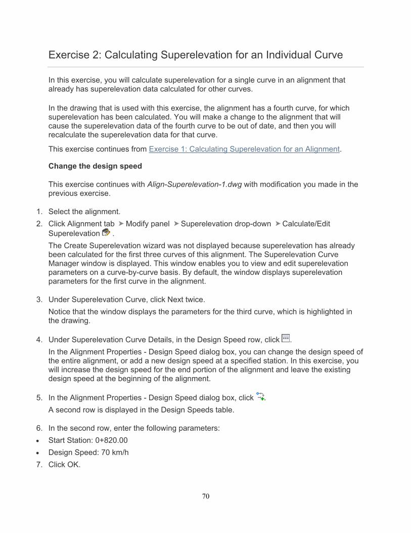
6. In the second row, enter the following parameters:
Start Station: 0+820.00
Design Speed: 70 km/h
7. Click OK.
71
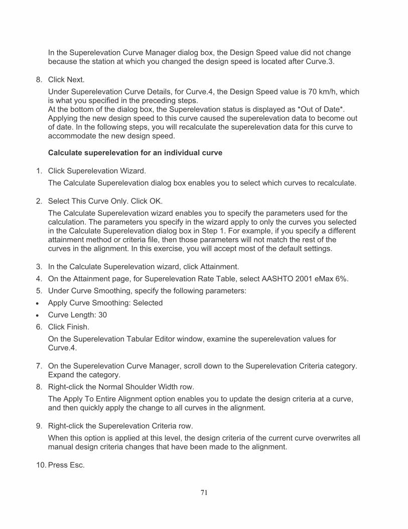
In the Superelevation Curve Manager dialog box, the Design Speed value did not change because the station at which you changed the design speed is located after Curve.3.
8. Click Next.
Under Superelevation Curve Details, for Curve.4, the Design Speed value is 70 km/h, which is what you specified in the preceding steps. At the bottom of the dialog box, the Superelevation status is displayed as *Out of Date*. Applying the new design speed to this curve caused the superelevation data to become out of date. In the following steps, you will recalculate the superelevation data for this curve to accommodate the new design speed.
Calculate superelevation for an individual curve
1. Click Superelevation Wizard.
The Calculate Superelevation dialog box enables you to select which curves to recalculate.
2. Select This Curve Only. Click OK.
The Calculate Superelevation wizard enables you to specify the parameters used for the calculation. The parameters you specify in the wizard apply to only the curves you selected in the Calculate Superelevation dialog box in Step 1. For example, if you specify a different attainment method or criteria file, then those parameters will not match the rest of the curves in the alignment. In this exercise, you will accept most of the default settings.
3. In the Calculate Superelevation wizard, click Attainment.
4. On the Attainment page, for Superelevation Rate Table, select AASHTO 2001 eMax 6%.
5. Under Curve Smoothing, specify the following parameters:
Apply Curve Smoothing: Selected
Curve Length: 30
6. Click Finish.
On the Superelevation Tabular Editor window, examine the superelevation values for Curve.4.
7. On the Superelevation Curve Manager, scroll down to the Superelevation Criteria category. Expand the category.
8. Right-click the Normal Shoulder Width row.
The Apply To Entire Alignment option enables you to update the design criteria at a curve, and then quickly apply the change to all curves in the alignment.
9. Right-click the Superelevation Criteria row.
When this option is applied at this level, the design criteria of the current curve overwrites all manual design criteria changes that have been made to the alignment.
10. Press Esc.

72
To continue this tutorial, go to Exercise 3: Creating a Superelevation View.
73
Exercise 3: Creating a Superelevation View
In this exercise, you will display superelevation data in a graph, which you can use to graphically edit superelevation data.
This exercise continues from Exercise 2: Calculating Superelevation for an Individual Curve.
Create a superelevation view
This exercise continues with Align-Superelevation-1.dwg with modification you made in the previous exercise.
1. Select the alignment.
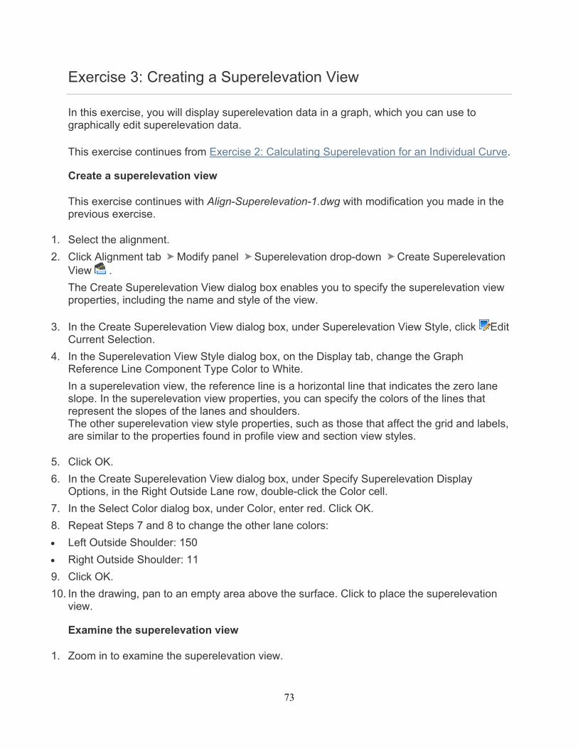
2. Click Alignment tab Modify panel Superelevation drop-down Create Superelevation View .
The Create Superelevation View dialog box enables you to specify the superelevation view properties, including the name and style of the view.
3. In the Create Superelevation View dialog box, under Superelevation View Style, click Edit Current Selection.
4. In the Superelevation View Style dialog box, on the Display tab, change the Graph Reference Line Component Type Color to White.
In a superelevation view, the reference line is a horizontal line that indicates the zero lane slope. In the superelevation view properties, you can specify the colors of the lines that represent the slopes of the lanes and shoulders. The other superelevation view style properties, such as those that affect the grid and labels, are similar to the properties found in profile view and section view styles.
5. Click OK.
6. In the Create Superelevation View dialog box, under Specify Superelevation Display Options, in the Right Outside Lane row, double-click the Color cell.
7. In the Select Color dialog box, under Color, enter red. Click OK.
8. Repeat Steps 7 and 8 to change the other lane colors:
Left Outside Shoulder: 150
Right Outside Shoulder: 11
9. Click OK.
10. In the drawing, pan to an empty area above the surface. Click to place the superelevation view.
Examine the superelevation view
1. Zoom in to examine the superelevation view.
74
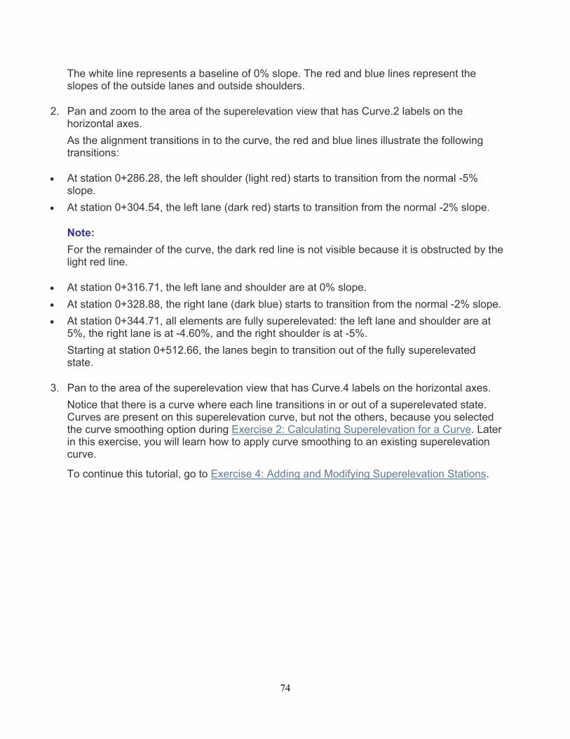
The white line represents a baseline of 0% slope. The red and blue lines represent the slopes of the outside lanes and outside shoulders.
2. Pan and zoom to the area of the superelevation view that has Curve.2 labels on the horizontal axes.
As the alignment transitions in to the curve, the red and blue lines illustrate the following transitions:
At station 0+286.28, the left shoulder (light red) starts to transition from the normal -5% slope.
At station 0+304.54, the left lane (dark red) starts to transition from the normal -2% slope.
Note:
For the remainder of the curve, the dark red line is not visible because it is obstructed by the light red line.
At station 0+316.71, the left lane and shoulder are at 0% slope.
At station 0+328.88, the right lane (dark blue) starts to transition from the normal -2% slope.
At station 0+344.71, all elements are fully superelevated: the left lane and shoulder are at 5%, the right lane is at -4.60%, and the right shoulder is at -5%.
Starting at station 0+512.66, the lanes begin to transition out of the fully superelevated state.
3. Pan to the area of the superelevation view that has Curve.4 labels on the horizontal axes.
Notice that there is a curve where each line transitions in or out of a superelevated state. Curves are present on this superelevation curve, but not the others, because you selected the curve smoothing option during Exercise 2: Calculating Superelevation for a Curve. Later in this exercise, you will learn how to apply curve smoothing to an existing superelevation curve.
To continue this tutorial, go to Exercise 4: Adding and Modifying Superelevation Stations.
75
Exercise 4: Adding and Modifying Superelevation Stations
In this exercise, you will resolve overlap between two superelevated curves by adding and removing critical stations, and then editing existing superelevation data.
This exercise continues from Exercise 3: Creating a Superelevation View.
Examine the superelevation parameters
This exercise continues with Align-Superelevation-1.dwg with modification you made in the previous exercise.
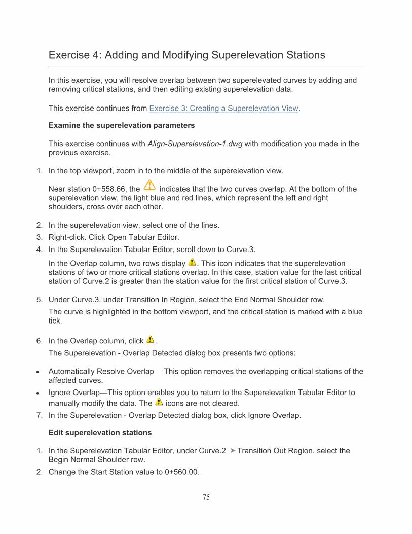
1. In the top viewport, zoom in to the middle of the superelevation view.
Near station 0+558.66, the indicates that the two curves overlap. At the bottom of the superelevation view, the light blue and red lines, which represent the left and right shoulders, cross over each other.
2. In the superelevation view, select one of the lines.
3. Right-click. Click Open Tabular Editor.
4. In the Superelevation Tabular Editor, scroll down to Curve.3.
In the Overlap column, two rows display . This icon indicates that the superelevation stations of two or more critical stations overlap. In this case, station value for the last critical station of Curve.2 is greater than the station value for the first critical station of Curve.3.
5. Under Curve.3, under Transition In Region, select the End Normal Shoulder row.
The curve is highlighted in the bottom viewport, and the critical station is marked with a blue tick.
6. In the Overlap column, click .
The Superelevation - Overlap Detected dialog box presents two options:
Automatically Resolve Overlap —This option removes the overlapping critical stations of the affected curves.
Ignore Overlap—This option enables you to return to the Superelevation Tabular Editor to manually modify the data. The icons are not cleared.
7. In the Superelevation - Overlap Detected dialog box, click Ignore Overlap.
Edit superelevation stations
1. In the Superelevation Tabular Editor, under Curve.2 Transition Out Region, select the Begin Normal Shoulder row.
2. Change the Start Station value to 0+560.00.
76
Remove a superelevation critical station
1. In the Superelevation Tabular Editor, under Curve.3 Transition In Region, select the End Normal Shoulder row.
2. Click .
The End Normal Shoulder superelevation critical station is removed.
Add a superelevation critical station
1. In the Superelevation Tabular Editor, select the Curve.3 row.
2. Click .
The Superelevation Tabular Editor is hidden, and you are prompted to specify a station along the alignment.
3. On the command line, enter 568. Press Enter.
A new manual station, which starts at station 0+568.00, is displayed in the Superelevation Tabular Editor.
4. Right-click the Manual Station. Click Assign Critical Station End Normal Shoulder.
5. In the End Normal Shoulder row, enter the following values:
Note:
The remaining columns are interpreted from these values.
Left Outside Shoulder: -5.00%
Left Outside Lane: -2.00%
Right Outside Lane: -2.00%
Right Outside Shoulder: -5.00%
Note: To import existing superelevation data from a CSV file, click .
Notice that the icons are no longer displayed in the Overlap column.
6. Click to close the Superelevation Tabular Editor.
To continue this tutorial, go to Exercise 5: Editing Superelevation Parameters Graphically.
77
Exercise 5: Editing Superelevation Parameters Graphically
In this exercise, you will use grips in a superelevation view to modify the superelevation cross slopes and critical station values.
This exercise continues from Exercise 4: Adding and Modifying Superelevation Stations.
Examine the grips
This exercise continues with Align-Superelevation-1.dwg with modification you made in the previous exercise.
1. In the Curve.4 portion of the superelevation view, click any of the red or blue lines.
A series of grips appears at each of the superelevation critical stations along each line, as well as on the superelevation view. You will learn the purpose of the grips later in this exercise.
2. Press Esc.
Move a critical station graphically
1. Near station 0+900.00, Ctrl+click the green Shoulder text.
Only the grips of the selected superelevation region are displayed.
2. Hover the cursor over the grip at station 0+908.44.
The cursor snaps to the grip, and a menu of options is displayed. You can use this grip to either change the station value, or add or remove a critical station.
3. Select Move End Normal Shoulder.
4. Move the grip to station 0+900.00. Click to place the grip.
The transition in region is updated.
Note: The new station value is also shown in the Superelevation Tabular Editor and Superelevation Curve Manager.
5. Press Esc.
Remove or apply curve smoothing
1. Pan to the transition out region of Curve.4.
2. Near station 1+147.69, Ctrl+click the light red curve.
3. Hover the cursor over the grip at station 1+148.59.
78
The cursor snaps to the grip, and a menu of options is displayed. You can use this grip to change the cross slope at this critical station, remove the grade break, or remove curve smoothing.
4. Select Remove Curve Smoothing.
The curve is removed from the grade break.
Note: You may use the same process to add curve smoothing to a grade break.
5. Press Esc.
Change the cross slope at a superelevation critical station
1. At station 1+148.59, hover the cursor over the grade grip.
When a grade grip is cyan, a grade break exists at the current location. Like other cyan grips in a superelevation view, a menu of options is displayed.
2. At station 1+116.45, hover the cursor over the grip.
When a grade grip is gray, the current location has a consistent grade. Because no grade break is present, the only option is to change the cross slope.
3. Click the grip to make it active.
4. Enter 1.5.
Notice that the grip color is now cyan. This happened because you created a grade break at the current location.
Change the cross slope between superelevation curves
1. Pan to the left until you see the grip near station 1+000.00.
2. Hover the cursor over the grip.
The cursor snaps to the grip, and a menu of options is displayed. You can use this grip to change the cross slope of either one or both of the shoulders or lanes between the previous and next superelevation critical stations. This grip is available in sections where lanes or shoulders are fully superelevated, as well as on tangents that are between curves.
3. Select Move Both Left and Right.
4. Enter 4.
The cross slopes of both the left and right shoulders are updated.