Embed Size (px)
Citation preview

Final ReportShiley School of Engineering, University of Portland
EE/CS 481A Senior Design ProjectMagnetic Manipulator
Team 125Chad Perkins (Spring Team Lead), John Olennikov,
Marley Rutkowski (Fall Team Lead) Benjamin Younce
Faculty Advisor: Dr. Robert AlbrightIndustrial Advisor: Andy McConnell
Client: Dr. Mark Utlaut
March 28th, 2014

2
Table of Contents
Introduction……….…………………………………………… 3
Technical Outcomes……….…………………………………………… 4
1-Arduino Microcontroller……….…………………………………………… 5
2-Computer……….…………………………………………… 8
3-Transistor Circuit……….…………………………………………… 9
4-Electromagnet……….…………………………………………… 10
5-Levitating Object……….…………………………………………… 10
6-Hall Sensors……….…………………………………………… 10
7-Hall Sensor Processing Circuit
……….…………………………………………… 11
8-Enable Switch……….…………………………………………… 11
9-System State LEDs……….…………………………………………… 12
10-Power Source……….…………………………………………… 12
Process Outcomes……….…………………………………………… 12
Assumptions……….…………………………………………… 12
Product Changes……….…………………………………………… 13

3
Milestones……….…………………………………………… 14
Risks……….…………………………………………… 14
Conclusion……….…………………………………………… 15
Appendices……….…………………………………………… 16
Appendix A: Milestones……….…………………………………………… 16
Appendix B: Circuit Schematic
……….…………………………………………… 18
Appendix C: Arduino Code……….…………………………………………… 19
Introduction Electromagnets have been used for a variety of different purposes, ranging
from picking up paper clips using a wire wrapped around a nail to MRI scanning and even magnetic levitation transportation systems. The Magnetic Manipulator project adds to the list by using an electromagnet controlled by a microcomputer to levitate a permanent magnet and move it up and down in the air.
The project began with research into the components that were required to levitate the magnet. This included a solenoid, two Hall sensors, and a microcomputer. Once the components arrived, the solenoid was tested to ensure that it would generate a strong enough magnetic field to levitate the magnet. Next, an Arduino microcomputer was used to generate a pulse width modulation (PWM) signal. The output from the Hall sensor was tuned in order to increase the precision of the values that Team 125 needed and to remove unnecessary outlying values. Next, in order to further increase Hall sensor output precision and have more processing power, the code was ported from the Arduino Uno to the Arduino Due. Using the Hall sensor output to the Arduino and a PID algorithm, the Arduino Due has been able to levitate the magnet for an indefinite amount of time. Figure 1 shows the finished Mag-Lev stand.
Some challenges faced with the circuit were increasing the precision of the Hall sensor outputs, and reducing noise. Another anticipated challenge was that our breadboard could not handle the amount of current we were sending through it, and would melt. The biggest challenge with the Arduino was porting the code from the Uno to the Due. The greatest difficulty in the porting process was finding documentation to implement the features that existed in the Uno, using the Due. The team was surprised with the sources of noise in the circuits and the lack of

4
documentation for the Due. Team 125 did very well in figuring out the circuits for tuning the Hall sensor output and troubleshooting the sources of noise in the circuit. The difficulties in porting the code from the Uno and Due could have been taken care of faster if more research was done into the documentation of the Due.
Fig 1. The Finished Mag-Lev
This report begins with the technical outcomes of the project. It then discusses the Arduino code and the different processes that control the PWM, read Hall sensor values, and send data to the Processing code. The computer and graphical user interface (GUI) sections talk about the components of the user interface and describe how the Processing code interacts with the Arduino. Each physical component is described in its function and how it contributes to the result of levitating the magnet. Next, the assumptions and changes to the project that the team made over the past six months will be addressed. The progress of the Mag-Lev project is described using the milestones, and is followed by a summarization of the risks, what went wrong and what did not. Finally, the paper is summarized with a conclusion.
Technical OutcomesOverall, the Magnetic Manipulator system was designed as planned in the
Requirements and Functional Specifications report. The only system component that was not included in the final product from the original design was the power regulator. This was because the component did not work as planned because of low quality parts and a bad design by the manufacturer. Since laboratory supplies were used as the power source instead, no additional regulation was needed. Additionally, an electromagnet monitoring circuit, a Hall sensor processing circuit, and some system-state LEDs were added. The primary components of the Mag-Lev are as planned in the original design as follows: Arduino, computer, electromagnet, Hall sensor, levitating object, power source, power transistor, and an enable switch. Figure 2 is a block diagram that depicts each of the major system components and

5
how they interact with each other. Detailed descriptions of each component are found below.
Fig 2. System Block Diagram
1-Arduino Microcontroller: The Arduino microcontroller is the central brains of Team 125’s system. It is responsible for interpreting commands from and providing information to the user, tracking the levitation of the magnet through the Hall sensor, and controlling the power given to the electromagnet via the transistor.
Input data from the user is received by the Arduino as bytes sent over a serial cable by the computer. When commands are available in its buffer, the Arduino reads in and interprets them in order to determine how the state of the system should be affected.
System state data is encoded by the Arduino and sent over serial cable to the computer in order to provide the user with information to improve system control.
Processed Hall sensor data is read in by the Arduino on an analog pin and interpreted in order to track the position of the levitating object at any given time.
Position data is interpreted by the Arduino in order to determine the how to control the electromagnet, given the current position of the levitating magnet and its desired position. A proportional-integral-derivative (PID) control algorithm is used to determine the percent duty cycle of the pulse width modulation (PWM) signal needed to keep the levitating object at (or get it to) the desired setpoint.
Arduino Code Overview:

6
This section gives a brief overview of the key characteristics of the Arduino controller code. This includes the system state machine structure, PWM generation, and the Hall data analogRead.
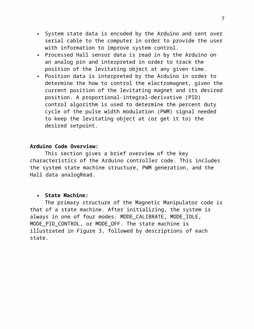
State Machine:The primary structure of the Magnetic Manipulator code is that of a state
machine. After initializing, the system is always in one of four modes: MODE_CALIBRATE, MODE_IDLE, MODE_PID_CONTROL, or MODE_OFF. The state machine is illustrated in Figure 3, followed by descriptions of each state.
Fig 3. System State Machine
MODE_CALIBRATE:After initialization the code it is set in this state. The system can also be set
into Calibration Mode if a recalibrate command is received, in which case it begins calibrating regardless of what mode it was previously in. In order for Calibration Mode to run properly, no object should be near the levitation area. In this mode the system first sets the coil PWM duty cycle to zero. It then continues increasing the duty cycle by small increments (defined by a system constant), taking many samples of the magnetic field strength at each level and storing them in an array of calibration values. These values are later used to find the duty cycle necessary to achieve a given field strength (varies based on the small changes in the input voltage and thus may not always be the same). The Calibration Mode is complete once it reaches a full duty cycle and the array of calibration values is full. At this point, the system switches to Idle.
MODE_IDLE:
7
In Idle Mode, the system is simply waiting for a levitation object to come into range. In this mode the system sets a default PWM duty cycle in order to orient any object that comes close, and then it waits. Once an object enters the initialized control interval, the system switches to PID control.
MODE_PID_CONTROL:PID Control Mode is the primary state of the system in which it levitates an
object in the sensor’s range. In this mode, the system updates the PWM duty cycle at a frequency of 1kHz. Each time it updates the new duty cycle is determined based on a PID control algorithm, which uses a current error term (P), an integral term (I), and a derivative term (D), each with a different weight to determine what the new PWM duty cycle should be in order to keep the levitating object at the current set point. This algorithm works such that if the object is below the setpoint, the new field strength will be greater, and it will be less if it is above the set point. If while in PID Control Mode, the object gets too close to the Hall sensor, the system will switch to Off Mode. If the object gets too far away, it will go back to Idle.
MODE_OFF:This mode is reached if the levitating object has gotten too close to the Mag-
Lev’s electromagnet. When in this mode, the electromagnet is turned off so that the object is not sucked up too high and permanently attaches to the soleoid. The system stays in Off Mode until the magnet gets within a defined tolerance of the current set point at which time the system is switched back into Control Mode.
PWM Generation:The PWM signal is essential in order to modulate the voltage to the
electromagnet in an analog fashion using the digital Arduino system. The standard PWM functions provided by Arduino did not provide the frequency customization nor the duty cycle percent precision that was required by this project. Thus, it was necessary to utilize the PWM macrocell onboard the ARM CPU. Once initialized by manipulating control bits, this macrocell produces a PWM signal at a constant frequency without any need of CPU time. The duty cycle percent is then manipulated by the system code by simply adjusting a 16 bit timer value (thus there are 2^16 possible PWM percentages).
Hall Data AnalogRead:Due to system noise and ADC (analog-to-digital-converter) inaccuracies,
performing a normal 12 bit analog read, when information on the current Hall signal value was needed, proved not to be accurate enough for the system. Therefore, two separate smoothing techniques were utilized in order to improve the data by

8
averaging over space and time. These techniques were keeping a moving mean over time and running multiple ADCs synchronously.
Synchronous ADCs: Normally in Arduino, one uses the analogRead method to get a digital
representation of a analog signal. When a system calls the analogRead method the system triggers an ADC to start an analog read, and waits until it is done (a process that takes a number of CPU cycles). At this time it receives one value and continues. In normal applications the time this takes is not a problem. However, when readings are being taken on the order of 100kHz (as is the case in this project), the fact that the CPU time to data throughput of this process of simple analogRead is relatively high will significantly bog down the system. In order to increase the data/CPU time ratio, a system timer was set to trigger at 100kHz. Eight ADCs connected to pins A0-A7 are triggered to automatically start converting synchronously on every clock trigger without the need of any intervention by the CPU. Once the ADC on channel 7 is finished converting, it triggers a system ISR (interrupt service routine) that collects the data from all 8 ADCs.
Moving Mean:In order to average values over time, the system keeps a moving mean. It
does this by always maintaining a sum of the 10 most recent Hall values produced by the ADCs (note the average of all 8 ADCs is considered one value). Every time the data from the ADCs is retrieved, the oldest value currently in the moving Sum is subtracted off. The new value is added in and stored in a circular array so that it can be subtracted off again once it is too old.
Retrieving Values:Both the synchronous ADCs and the moving mean are always running on the
system, whether or not a reading is needed at that time. When a when the system does need a value, all it needs to do to get an average of 80 samples is divide the current moving summed value by 10.
2-Computer: The laptop (or desktop) computer serves as the user interface for the magnetic manipulation system. The Arduino and the Processing code setup a connection using a handshake system. That way, both sides can ensure that they are in sync and can understand one another. The user is able to input commands into the GUI which are encoded and sent over serial cable to the Arduino to be processed. Even though this has not been tested, the GUI app has to buffer commands to make sure that they are not sent too fast for the Arduino to read

9
because of the serial queue size limit in the Arduino. Because the GUI runs on a computer, it has more processing power for data crunching and formatting. Therefore, to reduce the load on the Arduino, it only sends raw data to the GUI.
GUI Code OverView:In order to make it easier to understand what is going on in our system, the
Arduino sends data to the team’s Processing code, which formats and displays the data to the user. The Processing programming language was selected because that was the language that Marley had previously used to interface with the Arduino. The Graphical User Interface (GUI) is composed of buttons, labels, text fields, and graphs. Figure 4 displays the GUI that the team ended up with. Since all of these components use some of the same fields (x and y coordinates, height, width, etc), the object-oriented programming (OOP) methodology was selected over functional programming. As a result, changing layout, formats, and colors for the elements is greatly simplified.
The GUI initially was just going to be three labels with pulse frequency, magnetic field strength, the calculated object distance and two buttons to raise or lower the magnet. A console was later created to display data from the Arduino, and to manage the serial connection. In order to understand the PID algorithm, a graph was also included to graph the PWM, and the PID values, respectively. Because visual data is often much easier to understand than textual data, we are considering modifying the GUI in order to include multiple graphs to plot the permanent magnet’s position and the values of the PID algorithm.
Currently, the Arduino waits for the handshake from the Processing code in order to start its execution. However, because the purpose of the GUI is for formatting and displaying data, the GUI is not an essential component that is required to levitate the object.

10
Figure 4. The Mag-Lev GUI
3-Transistor Circuit: A transistor is necessary to control the power to the electromagnet provided by the power source. The power transistor is not controlled by a digital control signal, as originally envisioned, but rather by a high frequency PWM signal from the Arduino. As the duty cycle of the PWM signal is adjusted, the transistor effectively increases or decreases the voltage across the electromagnet.
For this project a TIP 120 Darlington pair transistor is used. The base of the transistor is wired to the Arduino PWM signal through a 1kΩ resistor so that there is a current to enable the transistor. The transistor is wired such that when it is enabled, it connects the ground of the electromagnet to the ground of the power source so that the coil is energized. When the transistor is off, the electromagnet is not grounded and therefore no current can flow through it. Therefore, the negative lead of the electromagnet is attached to the collector of the transistor and the emitter of the transistor is wired to ground.
Additionally, diodes are wired with their anode connected to the collector of the transistor (and the negative lead of the electromagnet), and their cathode attached to the incoming power (and the positive lead of the electromagnet). This is done so that any back-voltage created by the electromagnet when its power is cut will be shorted back to the power supply, rather than creating a backward surge in the circuit which could possibly damage the transistor and/or Arduino. The transistor circuit also features an LED (with resistor to control current flow) that is attached to the incoming control PWM signal and serves to indicate the present state of the transistor. The brighter the LED is the higher the present duty cycle of the PWM.
4-Electromagnet: The electromagnet creates the magnetic field that interacts with the levitating object, keeping it in place. It is activated and deactivated by the transistor that controls the power provided to it. As the duty cycle of the transistor (based on the PWM sent to it) is increased, the strength of the field of created by the electromagnet also increases.The strength of the field created by the electromagnet is reflected in the voltage outputs of both Hall sensors.
5-Levitating Object: The objective of Team 125 is to levitate a small object, weighing 5-10 grams. The team designed the Magnetic Manipulator to levitate a 1/2 x 1/8 inch disc neodymium magnet.
6-Hall Sensors:

11
Hall sensor data is used to gather information on the position of the levitating object. A Hall sensor varies its output voltage in response to the magnetic field it senses and the Arduino monitors this data as an analog input. The Hall sensor outputs a voltage between 0V and 5V. A voltage of 2.5V indicates no magnetic field, voltage below 2.5V indicates a negative field (magnetic field lines going down through the sensor), and a voltage above 2.5V indicates a positive field (magnetic field lines going up through the sensor). The magnitude of the Hall sensor value difference from 2.5V is proportional to the strength of the magnetic field present with sensitivity of the sensor at 5mV/G (millivolt / gauss).
A. The primary Hall sensor is positioned at the base of the electromagnet such that it is between the electromagnet and the levitating object. Therefore, the output of the Hall sensor at any given time contains information on the present state of the coil, as well as the proximity of a levitating object. As a levitating object gets closer to the Hall sensor, the field it creates at the point of the Hall sensor increases. From this information the Arduino is able to interpret the position of the levitating object at the present time.
B. Another Hall sensor is placed at opposite end of the electromagnet (on top) so that it measures the strength of the field produced by the electromagnet, but is not affected by an object in the levitation area. The value of the electromagnet Hall sensor is subtracted from that of the primary Hall sensor in order to give a value representative of just the magnetic field produced by the levitating object.
7-Hall Sensor Processing Circuit:The Hall sensor processing circuit was an addition from the system’s original
design. This circuit takes the signals from both Hall sensors and processes them to create a more useful signal for the Arduino. There are two separate processing circuits which provide signals for different stages of the system, and the Arduino can choose between these signals using a multiplexer controlled by the Arduino’s digital output pins.
The first signal processor provides a signal for system calibration measurements of the strength of the magnetic field at a given PWM duty cycle. The Hall sensor’s voltage is between 0V and 5V and the Arduino Due can only handle up to 3.3V so this circuit first uses a voltage divider to reduce the maximum voltage to 3.3V. Since for this project there should never be a negative magnetic field (Hall value less than 2.5V) this processor next subtracts 1.6V from the signal so that positive voltages only represent positive fields. Finally, it amplifies the signal back up so its maximum of 3.3V.
The second signal processor provides a signal optimized for general system operation. This processor subtracts the electromagnet Hall sensor value from the primary Hall sensor value using an operational amplifier, effectively removing all information about the present field strength of the electromagnet from the signal. Therefore, the signal only represents the magnetic field from the levitating object. This processing circuit is an alternative to the software subtraction of the electromagnetic field strength using a calibrated value which was originally planned,

12
but caused problems when there was magnetic flux. The signal processor takes the subtracted signal and amplifies it to a range of 0V to 3.3V before passing it on to the Arduino through a multiplexer, which gives the Arduino more reliable information about the levitating object than before.
8-Enable Switch: A physical two-state switch can be used to enable and disable the levitation system. The switch is connected to one of the Arduino’s digital input ports. When disabled, the electromagnet has no power supplied to it. When enabled, the system will work as specified.
9-System State LEDs:Three LEDs which are used to indicate the current state of the system at a given time were a useful addition to the original design. They are each individually controlled by a digital signal from the Arduino which triggers a transistor to power the LEDs from the external 5V power supply. The state indications and their meanings are displayed in Table 1.
Table 1. LED States
Red Yellow Green
Waiting for Serial
ON ON OFF
Calibrating ON ON ON
Idling OFF ON OFF
Stopped ON OFF OFF
PID Control OFF OFF ON
10-Power Source: The primary power source provides the energy necessary to activate the electromagnets. It was originally planned to use a single external power AC/DC converter regulated by a regulator to power the system. However, the power regulator purchased did not function as anticipated and sources of different values were required to power the Hall Processing circuit. Therefore, a single laboratory supply with both sources in parallel set at about 7.5V is used to provide the power

13
for the electromagnet. This supply can provide up to 6A of current. A second laboratory supply is used to provide +15V and -15V sources to power the op amps in the Hall processing circuit. This supply is also used to provide a 5V source for the system state LEDs. Each of these three sources can provide up to 3A if required. However, nowhere near this amount of current is necessary for their application.
Process Outcomes
AssumptionsThe assumptions of Team 125 were essentially the same at the beginning of
the project as they were at its conclusion, with a few exceptions. The assumption that two dimensional levitation would be achievable in two semesters did not hold true. This caused the group to rethink its main goal of the design project and decide to create stable one dimensional levitation instead of levitation with control in two dimensions. Another assumption the group made that did not hold true was that the Hall sensor would give accurate values. Unfortunately, the Hall sensor sent a value in a range that needed to be redefined in order to be read accurately by the Arduino. This was a setback, but Team 125 was able to work around it. Other assumptions proved true, such as the assumption that the solenoid that was selected had the strength to levitate a magnet two inches below it. The electromagnet works perfectly and was definitely the right choice for the job. Another assumption that was correct was that an Arduino Due would be necessary for interpreting the Hall sensor data because of its processing power and speed. Prototyping was performed with an Arduino Uno and the team found that it did not have enough power to perform the necessary operations.
There are some assumptions that were not in Team 125’s Functional Specifications, but should have been. For example, the team should have expected there to be some noise from the circuit leaking into the negative feedback system that would interfere with stable levitation. In addition, the team could have assumed that it would be necessary to use a permanent circuit board instead of a solderless breadboard because of durability and noise problems. Finally, the last assumption that was not on the Functional Specifications report was the assumption that the project would use more than one power supply, making it difficult to transport the project. These are complications that arose during the construction of the project that could have been accounted for but were not, and ultimately used up a lot of time.
Product ChangesThere are many differences between the plan the group started with for the
Mag-Lev project and the plan at its conclusion. As the project progressed, many changes have occurred in order to ensure that the magnetic levitation device would be completed on time. The most important change that had to be made was to throw out the idea of two dimensional control because of the complexity of one dimensional levitation using a digital system. This change happened in the middle of
14
Fall semester. It affected the finished product because the Mag-Lev is not as complex as originally predicted. It could have been caught earlier with better planning and a better understanding of digital systems. Another tweak that Team 125 made to the design of the Mag-Lev was to add a resolution enhancement circuit to the output of the Hall sensor mounted underneath the solenoid. This was made in the beginning of Spring semester because the Arduino was not getting reliable data from the Hall sensor. The result of this upgrade was that the Arduino got more accurate data from the Hall sensor and the levitation of the magnet was more stable. This could have been caught earlier by thinking about the accuracy and feedback needed in order to make the levitation more stable.
Other hardware additions include a second Hall sensor on top of the solenoid in order to get a read of its magnetic force, and an RC filter circuit in order to reduce the noise of the input voltage, which messes up the Hall sensor output. These changes both occurred in mid-March. Additionally, Team 125 had to find a suitable heat sink for the power transistor used to turn the electromagnet on and off because it heated up too much.This could have been prevented by purchasing our own heat sink and realizing that transistors can heat up when turned on and off rapidly. After implementing the heat sink update, the transistor has not had any further problems with overheating. The team has also implemented modifications to the GUI that deviate from the original plan because of previous changes to the design, such as adding a graph that displays the position of the levitating magnet and removing the 2D interface. These changes made to the design of the circuit allowed Team 125 to finish on time and with a working project.
MilestonesThe milestones (see Appendix A - Milestones) that were set at the beginning
of this project were intended to keep the team on track and ultimately finish the project on time, and they did just that. Almost all milestones were met or exceeded during the Fall semester. For example, the Requirements and Functional Specifications report and the Design Document were both submitted on time. The budget and prototype plan were also completed on time. Team 125 ordered parts before December 6th, 2013, so that milestone was completed early. Unfortunately, as Spring semester began milestones started getting missed for weeks, such as the prototype build being 100% complete, because of problems with noise and inaccurate Hall sensor values. These caused the group to implement some of the changes mentioned earlier in this section, such as a Hall sensor resolution circuit and an RC filter circuit to reduce noise. The group originally planned to have one dimensional levitation working by February 21st, but that did not happen because of complications with switching code form the Arduino Uno to the Arduino Due and inaccurate Hall sensor outputs. These milestones have generally kept Team 125 on track since the beginning of the academic year and have been one of the reasons that the project will be completed on time.

15
RisksSome of the risks that were planned for happened, and some did not. The first
risk that was planned for was that parts that the team ordered would not get to the school in time. This fear turned out to be unfounded, as all parts that were ordered were at the school by the beginning of Spring semester. The next risk listed in the Functional Specifications report was that the solenoid the team ordered would not be strong enough to levitate the magnet that was chosen. This, too, did not occur. One risk that was planned for did occur: two dimensional movement turned out to be much harder than the team had anticipated. So hard, in fact, that Team 125 did not reach two dimensional movement at all. The contingency plan worked; the team decided that if two dimensional movement was too hard, the focus of the project would turn to one dimensional levitation instead. Another risk was that the Arduino Due or Hall sensor would not be able to process the information as fast or accurately as required. This occurred because the Hall sensor output needed to have more resolution. The team was able to get away with implementing a fix instead of ordering new parts. The last risk that Team 125 planned for and occurred was that a part malfunctioned or broke. Team 125 bought two voltage regulators of the same type, from the same company, for a power supply. They did not work because of poor quality. These parts were necessary for creating a custom power source, but instead of ordering more low-quality parts, the group decided to use some power supplies from the senior design laboratory. This was a low-cost fix that allowed Team 125 to continue construction and testing of the prototype without losing time. The rest of the planned risks were incorrect schematics, insufficient laboratory space, sickness of a team member, and a broken prototype. None of these risks occurred.
One problem that occurred, but was not accounted for, was a couple of snow days in early Spring semester that prevented the group from working together. This slowed down testing and debugging of the circuit and was a contributing factor to Team 125 missing the “Prototype 100% Complete milestone”. This should have had a contingency plan that involved meeting again at a later date or redistributing tasks to people who were able to come in to work on the circuit, which would have minimized or prevented losing time. Overall, Team 125’s contingency plans were effective when necessary and helped the team finish the project on time.
ConclusionTeam 125 has developed a system that will achieve stable magnetic
levitation. All objectives have been accomplished except for two dimensional control, because of the complexity required to design the system. When developing Team 125’s system, the team faced lots of trial and error testing in order to develop the code to make the device work properly. Therefore, one of the team’s biggest challenges was testing the Magnetic Manipulator, and the potential of accidentally

16
damaging system components was present throughout the trial process. To improve design in a future project, two Hall sensors should be used, one above and one below the electromagnet. This allows for greater accuracy that Team 125’s design lacked until near the end of the project. Although the team’s ultimate goal of 2D magnetic manipulation was a stretch on the skills of each team member, the members of Team 125 are proud that they provided themselves with goals of increasing difficulty and achievable milestones that led to the ultimate success of the Magnetic Manipulator.
Appendix AMilestones (Fall Semester 2013 and Spring Semester 2014)Note: Major Milestone deadlines and descriptions are indicated in bold.
Due Date / Date Completed:
Description: Type:
Fri 13 Sep / Fri 13 Sep
Complete Initial Draft of All Sections of the Functional Specifications
Minor
Fri 20 Sep / Fri 13 Sep
Complete Functional Specifications, first complete draft (ver. 0.9)
Minor
Fri 27 Sep / Fri 27 Sep
Complete Functional Specifications, advisor-approved draft (ver. 0.95)Present September Program Review
MinorMinor
Fri 04 Oct / Fri 04 Oct
Complete Functional Specifications, final draft (ver. 1.0)
Major
Fri 11 Oct / Fri 11 Oct Create Parts List, to include pricing and sources. Minor
14 Oct-18 Oct Fall Break
Fri 25 Oct / Fri 25 Oct Present October Program ReviewCreate initial budgetDetermine lead times for parts and create an
MinorMinorMinor

17
ordering schedule accordingly.
Fri 01 Nov / Fri 01 Nov
Complete Design Document, first complete draft (ver. 0.9)
Minor
Fri 08 Nov / Fri 01 Nov
Complete Design Document, advisor-approved draft (ver. 0.95)Complete Final Budget Draft
MinorMinor
Fri 15 Nov / Fri 15 Nov
Complete Design Document, final draft (ver. 1.0)Complete Final Budget
MajorMajor
Fri 22 Nov / Fri 22 Nov
Create initial plan for prototype build. Minor
28-29 Nov Thanksgiving Break
Fri 29 Nov / Fri 29 Nov
Present November Program Review Minor
Fri 6 Dec / Fri 6 Dec Finalize prototype plansDetermine lead time for any technician help.All parts purchased or ordered
MinorMinorMajor
13 Dec-10 Jan Christmas Vacation
Fri 17 Jan / Fri 17 Jan Begin programming for Arduino Minor
Fri 24 Jan / Fri 24 Jan
Present January Program ReviewBegin prototype build
MinorMajor
Fri 31 Jan / Fri 31 Jan
Prototype build 50% complete Major
Fri 7 Feb / Fri 28 Feb Prototype build 100% completeBegin testing/debugging of prototype
MajorMajor
Fri 14 Feb / Fri 14 Feb Present February Program Review Minor
Fri 21 Feb / Fri 21 Mar
Have at least 1 dimensional movement working Major
Fri 28 Feb / Fri 28 Feb
Comprehensive Exams Major

18
Fri 07 Mar / Fri 07 Mar Complete Final Report Document initial write Minor
14 Mar-18 Mar Spring Break
Fri 21 Mar / Fri 21 Mar Complete Final Report, first complete draft (ver. 0.9) Minor
Fri 28 Mar / Fri 28 Mar Complete Final Report, advisor-approved draft (ver. 0.95)
Minor
Fri 04 Apr Present Final Program Review with Demonstration Complete Final Report, final draft (ver. 1.0)
Major
Major
Tue 08 Apr Present Project on Founder’s Day Major
Thu 17 Apr Present “Post Mortem” Review of Project Minor
Appendix BCircuit Diagram
19
Appendix CArduino Code

20

21

22

23

24

25

26

27