Embed Size (px)
Citation preview
Pentacam.
Airborne Multi-Spectral Imager
Instruction Manual
January 2008
Version 1.01
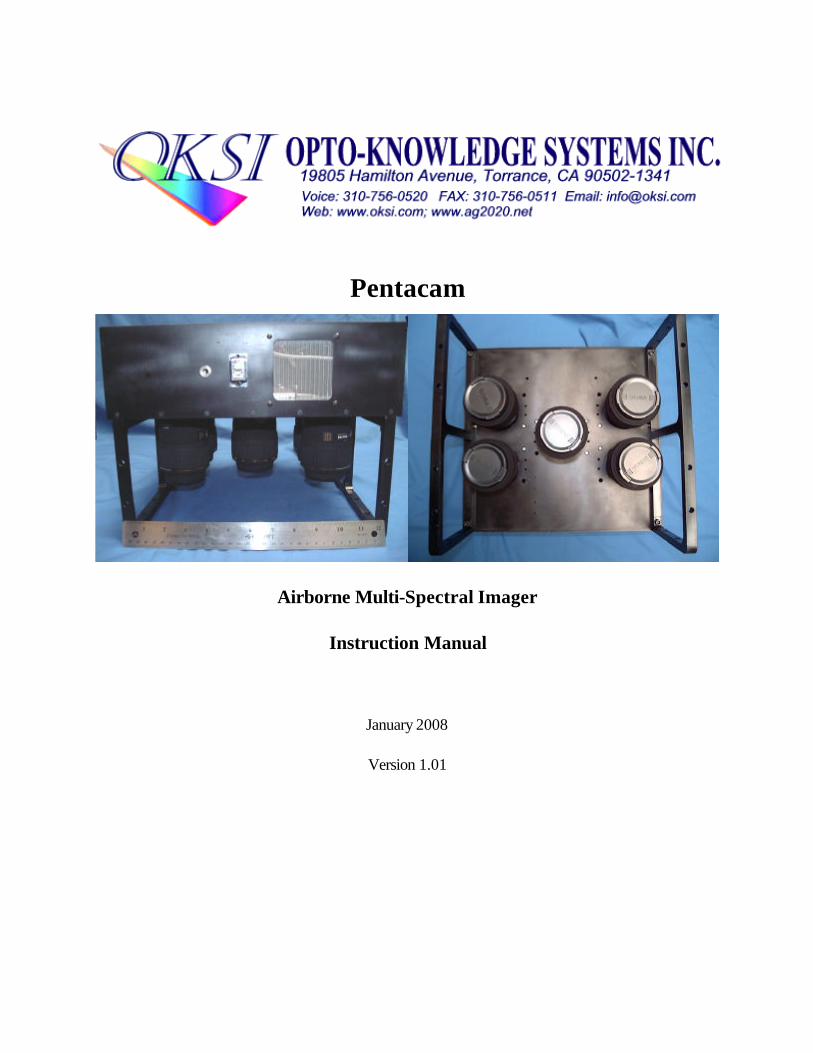
Table of Contents
36Specification Sheet13 . . . . . . . . . . . . . . . . . . . . . . . . . . . . . . . . . . . . . . . . . . . . . . . . . . . . . . .35Installing the Pentacam software to additional computers12 . . . . . . . . . . . . . . . . . . . . . . .31Radiometric calibration software11.2 . . . . . . . . . . . . . . . . . . . . . . . . . . . . . . . . . . . . . . . . . . .30Co-registration software11.1 . . . . . . . . . . . . . . . . . . . . . . . . . . . . . . . . . . . . . . . . . . . . . . . . . .29ENVI Software11 . . . . . . . . . . . . . . . . . . . . . . . . . . . . . . . . . . . . . . . . . . . . . . . . . . . . . . . . .27Mechanical and Electrical Specifications10 . . . . . . . . . . . . . . . . . . . . . . . . . . . . . . . . . . . . .27Modulation Transfer Function9 . . . . . . . . . . . . . . . . . . . . . . . . . . . . . . . . . . . . . . . . . . . . .26Settings for Airborne Imaging8 . . . . . . . . . . . . . . . . . . . . . . . . . . . . . . . . . . . . . . . . . . . . . .26Camera gain linearity7.1 . . . . . . . . . . . . . . . . . . . . . . . . . . . . . . . . . . . . . . . . . . . . . . . . . . . . .23Radiometric Calibration7 . . . . . . . . . . . . . . . . . . . . . . . . . . . . . . . . . . . . . . . . . . . . . . . . . . .22Image files6.2 . . . . . . . . . . . . . . . . . . . . . . . . . . . . . . . . . . . . . . . . . . . . . . . . . . . . . . . . . . . . . .22GPS and AHRS files6.1 . . . . . . . . . . . . . . . . . . . . . . . . . . . . . . . . . . . . . . . . . . . . . . . . . . . . .22Files and Headers6 . . . . . . . . . . . . . . . . . . . . . . . . . . . . . . . . . . . . . . . . . . . . . . . . . . . . . . .22Frame Rate Study5 . . . . . . . . . . . . . . . . . . . . . . . . . . . . . . . . . . . . . . . . . . . . . . . . . . . . . . .19Alignment / boresight4.6.3 . . . . . . . . . . . . . . . . . . . . . . . . . . . . . . . . . . . . . . . . . . . . . . . . . . . . .16Settings menu4.6.2 . . . . . . . . . . . . . . . . . . . . . . . . . . . . . . . . . . . . . . . . . . . . . . . . . . . . . . . . . . .16File menu4.6.1 . . . . . . . . . . . . . . . . . . . . . . . . . . . . . . . . . . . . . . . . . . . . . . . . . . . . . . . . . . . . . . .16Additional menus4.6 . . . . . . . . . . . . . . . . . . . . . . . . . . . . . . . . . . . . . . . . . . . . . . . . . . . . . . . .15Zoom control4.5 . . . . . . . . . . . . . . . . . . . . . . . . . . . . . . . . . . . . . . . . . . . . . . . . . . . . . . . . . . .15Live view controls4.4 . . . . . . . . . . . . . . . . . . . . . . . . . . . . . . . . . . . . . . . . . . . . . . . . . . . . . . .14GPS/AHRS control and display4.3 . . . . . . . . . . . . . . . . . . . . . . . . . . . . . . . . . . . . . . . . . . . .13Video controls4.2 . . . . . . . . . . . . . . . . . . . . . . . . . . . . . . . . . . . . . . . . . . . . . . . . . . . . . . . . . .13Image display4.1 . . . . . . . . . . . . . . . . . . . . . . . . . . . . . . . . . . . . . . . . . . . . . . . . . . . . . . . . . . .12Software4 . . . . . . . . . . . . . . . . . . . . . . . . . . . . . . . . . . . . . . . . . . . . . . . . . . . . . . . . . . . . . . .10Driver Installation3 . . . . . . . . . . . . . . . . . . . . . . . . . . . . . . . . . . . . . . . . . . . . . . . . . . . . . . . .6Bandpass Filter Installation2 . . . . . . . . . . . . . . . . . . . . . . . . . . . . . . . . . . . . . . . . . . . . . . . . .5Optics1.4 . . . . . . . . . . . . . . . . . . . . . . . . . . . . . . . . . . . . . . . . . . . . . . . . . . . . . . . . . . . . . . . . . .4External connections1.3 . . . . . . . . . . . . . . . . . . . . . . . . . . . . . . . . . . . . . . . . . . . . . . . . . . . . . .3Camera alignment hardware1.2 . . . . . . . . . . . . . . . . . . . . . . . . . . . . . . . . . . . . . . . . . . . . . . . .2Pentacam sensor mounting1.1 . . . . . . . . . . . . . . . . . . . . . . . . . . . . . . . . . . . . . . . . . . . . . . . . .1Sensor Hardware1 . . . . . . . . . . . . . . . . . . . . . . . . . . . . . . . . . . . . . . . . . . . . . . . . . . . . . . . . .
PageSection
Pentacam Instruction Manual Version 1.0 OKSI
List of Figures
31RGB co-registration image41 . . . . . . . . . . . . . . . . . . . . . . . . . . . . . . . . . . . . . . . . . . . . . . . . . . . . . . .30Reference cube pop-up40 . . . . . . . . . . . . . . . . . . . . . . . . . . . . . . . . . . . . . . . . . . . . . . . . . . . . . . . . .29Pentacam on ENVI toolbar39 . . . . . . . . . . . . . . . . . . . . . . . . . . . . . . . . . . . . . . . . . . . . . . . . . . . . . .29Pentacam electrical schematic38 . . . . . . . . . . . . . . . . . . . . . . . . . . . . . . . . . . . . . . . . . . . . . . . . . . . .28Pentacam dimensions - 237 . . . . . . . . . . . . . . . . . . . . . . . . . . . . . . . . . . . . . . . . . . . . . . . . . . . . . . . .28Pentacam dimensions - 136 . . . . . . . . . . . . . . . . . . . . . . . . . . . . . . . . . . . . . . . . . . . . . . . . . . . . . . . .26Normalized response vs. camera gain35 . . . . . . . . . . . . . . . . . . . . . . . . . . . . . . . . . . . . . . . . . . . . . .25Calibration data34 . . . . . . . . . . . . . . . . . . . . . . . . . . . . . . . . . . . . . . . . . . . . . . . . . . . . . . . . . . . . . . . .25Calibration setup using a calibrated irradiance lamp33 . . . . . . . . . . . . . . . . . . . . . . . . . . . . . . . . . .23Irradiance calculation with bandpass filter32 . . . . . . . . . . . . . . . . . . . . . . . . . . . . . . . . . . . . . . . . . .22Crosshair on alignment target31 . . . . . . . . . . . . . . . . . . . . . . . . . . . . . . . . . . . . . . . . . . . . . . . . . . . . .21Adjustment tool and hardware30 . . . . . . . . . . . . . . . . . . . . . . . . . . . . . . . . . . . . . . . . . . . . . . . . . . . .20Alignment pop-up29 . . . . . . . . . . . . . . . . . . . . . . . . . . . . . . . . . . . . . . . . . . . . . . . . . . . . . . . . . . . . . .19Set Directory pop-up28 . . . . . . . . . . . . . . . . . . . . . . . . . . . . . . . . . . . . . . . . . . . . . . . . . . . . . . . . . . .18Gain/Offset pop-up27 . . . . . . . . . . . . . . . . . . . . . . . . . . . . . . . . . . . . . . . . . . . . . . . . . . . . . . . . . . . . .17Camera Settings pop-up26 . . . . . . . . . . . . . . . . . . . . . . . . . . . . . . . . . . . . . . . . . . . . . . . . . . . . . . . . .16Settings menu selection25 . . . . . . . . . . . . . . . . . . . . . . . . . . . . . . . . . . . . . . . . . . . . . . . . . . . . . . . . . .16File menu selection24 . . . . . . . . . . . . . . . . . . . . . . . . . . . . . . . . . . . . . . . . . . . . . . . . . . . . . . . . . . . . . .15Live view23 . . . . . . . . . . . . . . . . . . . . . . . . . . . . . . . . . . . . . . . . . . . . . . . . . . . . . . . . . . . . . . . . . . . . . .14GPS/AHRS22 . . . . . . . . . . . . . . . . . . . . . . . . . . . . . . . . . . . . . . . . . . . . . . . . . . . . . . . . . . . . . . . . . . .13Video controls21 . . . . . . . . . . . . . . . . . . . . . . . . . . . . . . . . . . . . . . . . . . . . . . . . . . . . . . . . . . . . . . . . .13Graphical user interface20 . . . . . . . . . . . . . . . . . . . . . . . . . . . . . . . . . . . . . . . . . . . . . . . . . . . . . . . . . .12Sixth driver installation pop-up19 . . . . . . . . . . . . . . . . . . . . . . . . . . . . . . . . . . . . . . . . . . . . . . . . . . . .12Fifth driver installation pop-up18 . . . . . . . . . . . . . . . . . . . . . . . . . . . . . . . . . . . . . . . . . . . . . . . . . . . .11Fourth driver installation pop-up17 . . . . . . . . . . . . . . . . . . . . . . . . . . . . . . . . . . . . . . . . . . . . . . . . . .11Third diver installation pop-up16 . . . . . . . . . . . . . . . . . . . . . . . . . . . . . . . . . . . . . . . . . . . . . . . . . . . .10Second driver installation pop-up15 . . . . . . . . . . . . . . . . . . . . . . . . . . . . . . . . . . . . . . . . . . . . . . . . .10Initial driver installation pop-up14 . . . . . . . . . . . . . . . . . . . . . . . . . . . . . . . . . . . . . . . . . . . . . . . . . . .9Filter holder removal13 . . . . . . . . . . . . . . . . . . . . . . . . . . . . . . . . . . . . . . . . . . . . . . . . . . . . . . . . . . . . .9Set screw loosening12 . . . . . . . . . . . . . . . . . . . . . . . . . . . . . . . . . . . . . . . . . . . . . . . . . . . . . . . . . . . . . .8Filter cover removal11 . . . . . . . . . . . . . . . . . . . . . . . . . . . . . . . . . . . . . . . . . . . . . . . . . . . . . . . . . . . . . .8Spring removal10 . . . . . . . . . . . . . . . . . . . . . . . . . . . . . . . . . . . . . . . . . . . . . . . . . . . . . . . . . . . . . . . . . .7Pentacam system with cover and fore optics removed9 . . . . . . . . . . . . . . . . . . . . . . . . . . . . . . . . .7Filter holder8 . . . . . . . . . . . . . . . . . . . . . . . . . . . . . . . . . . . . . . . . . . . . . . . . . . . . . . . . . . . . . . . . . . . .6Imaging sensor with filter cover7 . . . . . . . . . . . . . . . . . . . . . . . . . . . . . . . . . . . . . . . . . . . . . . . . . . . .5C-style mounting provisions6 . . . . . . . . . . . . . . . . . . . . . . . . . . . . . . . . . . . . . . . . . . . . . . . . . . . . . . .5External connections5 . . . . . . . . . . . . . . . . . . . . . . . . . . . . . . . . . . . . . . . . . . . . . . . . . . . . . . . . . . . . .4Alignment hardware4 . . . . . . . . . . . . . . . . . . . . . . . . . . . . . . . . . . . . . . . . . . . . . . . . . . . . . . . . . . . . . .3Pentacam mounting3 . . . . . . . . . . . . . . . . . . . . . . . . . . . . . . . . . . . . . . . . . . . . . . . . . . . . . . . . . . . . . .2Camera housing2 . . . . . . . . . . . . . . . . . . . . . . . . . . . . . . . . . . . . . . . . . . . . . . . . . . . . . . . . . . . . . . . . .1System components1 . . . . . . . . . . . . . . . . . . . . . . . . . . . . . . . . . . . . . . . . . . . . . . . . . . . . . . . . . . . . . .
PageTitleFigure
Pentacam Instruction Manual Version 1.0 OKSI
34Image cube save pop-up46 . . . . . . . . . . . . . . . . . . . . . . . . . . . . . . . . . . . . . . . . . . . . . . . . . . . . . . . .33Dark field file selection pop-up45 . . . . . . . . . . . . . . . . . . . . . . . . . . . . . . . . . . . . . . . . . . . . . . . . . . .33Gain image file selection pop-up44 . . . . . . . . . . . . . . . . . . . . . . . . . . . . . . . . . . . . . . . . . . . . . . . . . .32DN pop-up43 . . . . . . . . . . . . . . . . . . . . . . . . . . . . . . . . . . . . . . . . . . . . . . . . . . . . . . . . . . . . . . . . . . . .32Exposure time and f/# inputs42 . . . . . . . . . . . . . . . . . . . . . . . . . . . . . . . . . . . . . . . . . . . . . . . . . . . . .
List of Tables
34Contents of radiance cube header file16 . . . . . . . . . . . . . . . . . . . . . . . . . . . . . . . . . . . . . . . . . . . . . .27Pentacam’s MTF results15 . . . . . . . . . . . . . . . . . . . . . . . . . . . . . . . . . . . . . . . . . . . . . . . . . . . . . . . . .27Suggested ‘starting point’ camera settings for airborne imaging14 . . . . . . . . . . . . . . . . . . . . . . . . .24Calibration camera settings13 . . . . . . . . . . . . . . . . . . . . . . . . . . . . . . . . . . . . . . . . . . . . . . . . . . . . . . .22Frame rate study12 . . . . . . . . . . . . . . . . . . . . . . . . . . . . . . . . . . . . . . . . . . . . . . . . . . . . . . . . . . . . . . .20Alignment controls11 . . . . . . . . . . . . . . . . . . . . . . . . . . . . . . . . . . . . . . . . . . . . . . . . . . . . . . . . . . . . . .18Gain/Offset controls10 . . . . . . . . . . . . . . . . . . . . . . . . . . . . . . . . . . . . . . . . . . . . . . . . . . . . . . . . . . . . .17Camera Setting controls9 . . . . . . . . . . . . . . . . . . . . . . . . . . . . . . . . . . . . . . . . . . . . . . . . . . . . . . . . .16Digital zoom controls8 . . . . . . . . . . . . . . . . . . . . . . . . . . . . . . . . . . . . . . . . . . . . . . . . . . . . . . . . . . . .15Live view controls7 . . . . . . . . . . . . . . . . . . . . . . . . . . . . . . . . . . . . . . . . . . . . . . . . . . . . . . . . . . . . . .14GPS/AHRS controls and display6 . . . . . . . . . . . . . . . . . . . . . . . . . . . . . . . . . . . . . . . . . . . . . . . . . .14Video capture controls5 . . . . . . . . . . . . . . . . . . . . . . . . . . . . . . . . . . . . . . . . . . . . . . . . . . . . . . . . . .6Dimensions allocated for bandpass filter4 . . . . . . . . . . . . . . . . . . . . . . . . . . . . . . . . . . . . . . . . . . . . .6Lens specifications3 . . . . . . . . . . . . . . . . . . . . . . . . . . . . . . . . . . . . . . . . . . . . . . . . . . . . . . . . . . . . . . .3Camera housing component description2 . . . . . . . . . . . . . . . . . . . . . . . . . . . . . . . . . . . . . . . . . . . . .1System level component description1 . . . . . . . . . . . . . . . . . . . . . . . . . . . . . . . . . . . . . . . . . . . . . . . .
PageTitleTable
Pentacam Instruction Manual Version 1.0 OKSI
1 SENSOR HARDWARE
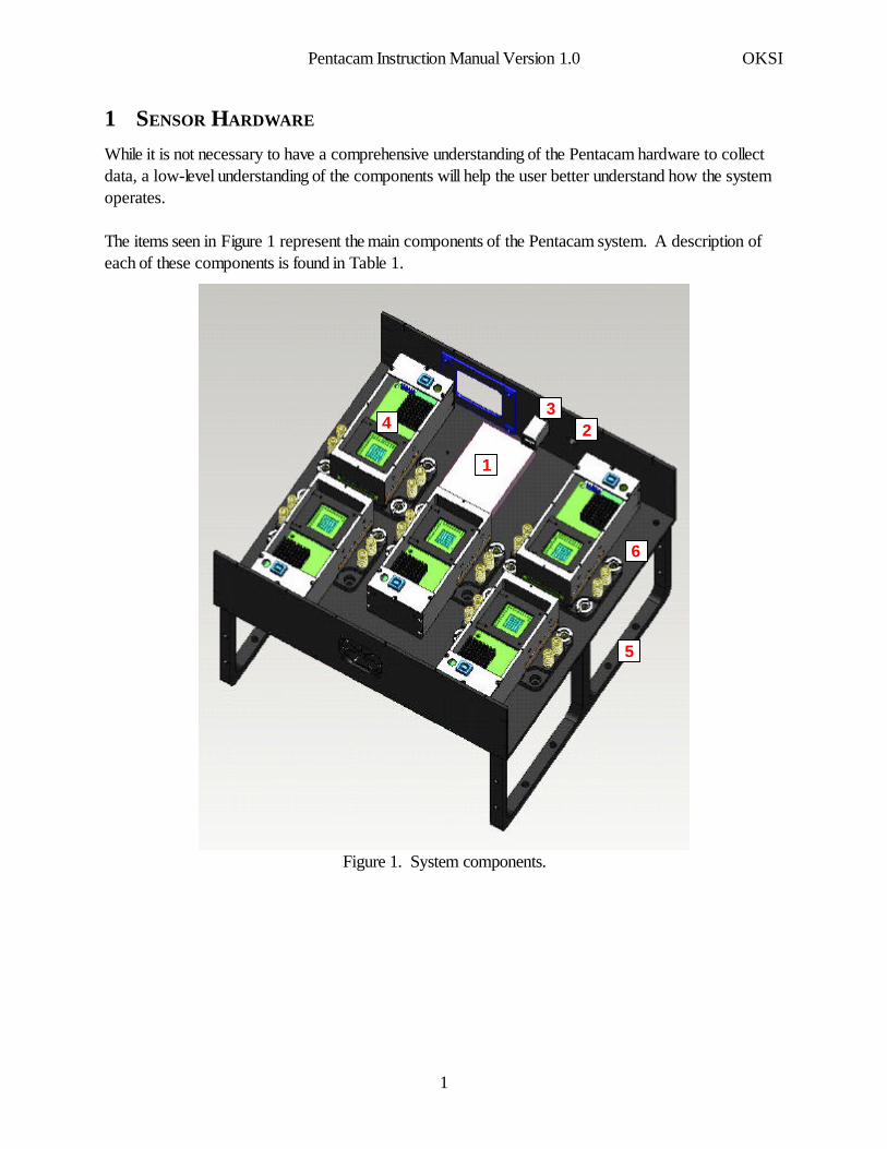
While it is not necessary to have a comprehensive understanding of the Pentacam hardware to collectdata, a low-level understanding of the components will help the user better understand how the systemoperates.
The items seen in Figure 1 represent the main components of the Pentacam system. A description ofeach of these components is found in Table 1.
1
23
4
5
6
Figure 1. System components.
Pentacam Instruction Manual Version 1.0 OKSI
1
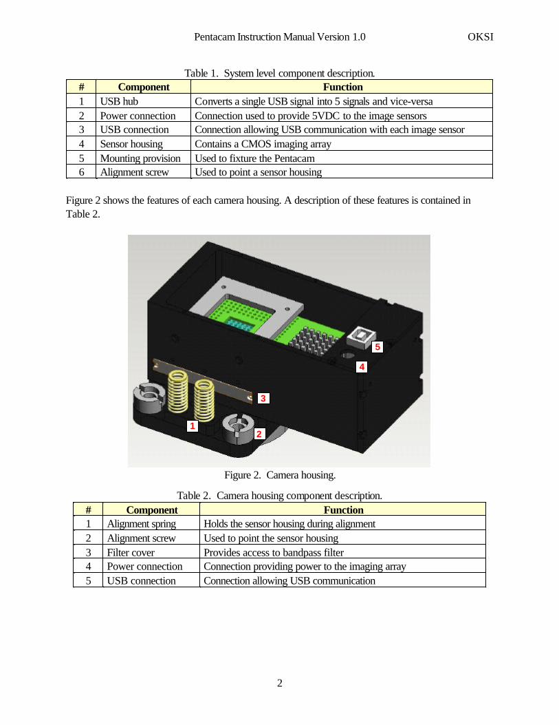
Table 1. System level component description.
Used to point a sensor housingAlignment screw6Used to fixture the PentacamMounting provision5Contains a CMOS imaging arraySensor housing4Connection allowing USB communication with each image sensorUSB connection3Connection used to provide 5VDC to the image sensorsPower connection2Converts a single USB signal into 5 signals and vice-versaUSB hub1
FunctionComponent#
Figure 2 shows the features of each camera housing. A description of these features is contained inTable 2.
5
4
3
21
Figure 2. Camera housing.
Table 2. Camera housing component description.
Connection allowing USB communication USB connection5Connection providing power to the imaging arrayPower connection4Provides access to bandpass filterFilter cover3Used to point the sensor housingAlignment screw2Holds the sensor housing during alignmentAlignment spring1
FunctionComponent#
Pentacam Instruction Manual Version 1.0 OKSI
2
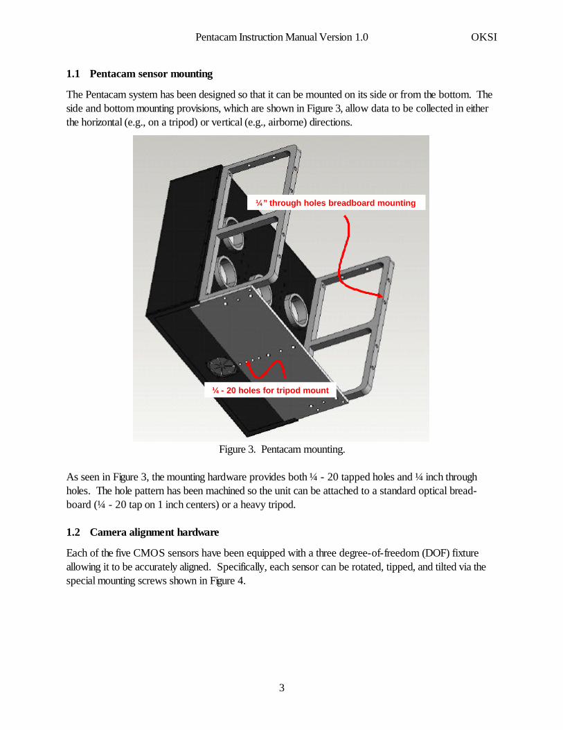
1.1 Pentacam sensor mounting
The Pentacam system has been designed so that it can be mounted on its side or from the bottom. Theside and bottom mounting provisions, which are shown in Figure 3, allow data to be collected in eitherthe horizontal (e.g., on a tripod) or vertical (e.g., airborne) directions.
¼ - 20 holes for tripod mount
¼” through holes breadboard mounting
Figure 3. Pentacam mounting.
As seen in Figure 3, the mounting hardware provides both ¼ - 20 tapped holes and ¼ inch throughholes. The hole pattern has been machined so the unit can be attached to a standard optical bread-board (¼ - 20 tap on 1 inch centers) or a heavy tripod.
1.2 Camera alignment hardware
Each of the five CMOS sensors have been equipped with a three degree-of-freedom (DOF) fixtureallowing it to be accurately aligned. Specifically, each sensor can be rotated, tipped, and tilted via thespecial mounting screws shown in Figure 4.
Pentacam Instruction Manual Version 1.0 OKSI
3
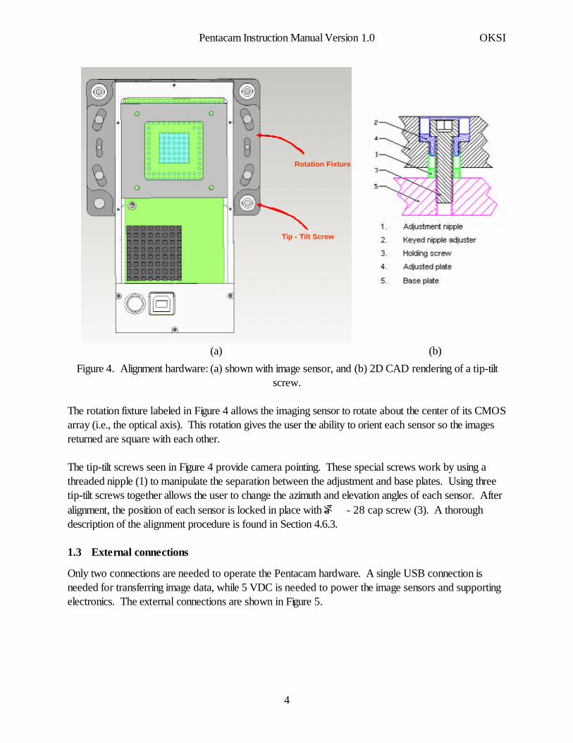
(b)(a)
Tip - Tilt Screw
Rotation Fixture
Figure 4. Alignment hardware: (a) shown with image sensor, and (b) 2D CAD rendering of a tip-tiltscrew.
The rotation fixture labeled in Figure 4 allows the imaging sensor to rotate about the center of its CMOSarray (i.e., the optical axis). This rotation gives the user the ability to orient each sensor so the imagesreturned are square with each other.
The tip-tilt screws seen in Figure 4 provide camera pointing. These special screws work by using athreaded nipple (1) to manipulate the separation between the adjustment and base plates. Using threetip-tilt screws together allows the user to change the azimuth and elevation angles of each sensor. Afteralignment, the position of each sensor is locked in place with a ¼ - 28 cap screw (3). A thoroughdescription of the alignment procedure is found in Section 4.6.3.
1.3 External connections
Only two connections are needed to operate the Pentacam hardware. A single USB connection isneeded for transferring image data, while 5 VDC is needed to power the image sensors and supportingelectronics. The external connections are shown in Figure 5.
Pentacam Instruction Manual Version 1.0 OKSI
4

USB
+5VDC
Figure 5. External connections.
1.4 Optics
Each of the five imaging sensors has a provision for C-mount fore optics. The C-style mounting provi-sions are shown in Figure 6.
‘C’ mount thread
Figure 6. C-style mounting provisions.
While C-style lens mounts have been chosen for Pentacam’s sensors, adapters can be used forF-mount lenses.
Pentacam’s 1.3 megapixel (1,280×1,024) CMOS arrays require a lens capable of producing a 19.67mm image circle. Therefore, F-mount and large format C-mount lenses are needed to prevent image
Pentacam Instruction Manual Version 1.0 OKSI
5
degradation due to vignetting. Five F-mount Sigma lenses (f = 105 mm) and five F-mount Nikkor lens(f = 35 mm) have been shipped with the Pentacam hardware. The mechanical specifications of theselenses are listed in Table 3.
Table 3. Lens specifications.
FFMount53 mm97.5 mmLength (when focused to ∞)
64.5 mm74 mmDiameter205 g457 gMass
f/2 - f/22f/2.8 - f/32Iris RangeNikkor (f = 35 mm)Sigma (f = 105 mm)Feature
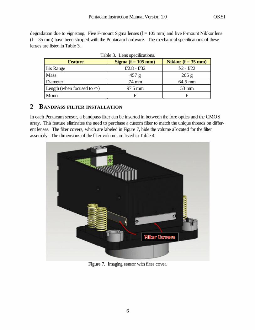
2 BANDPASS FILTER INSTALLATION
In each Pentacam sensor, a bandpass filter can be inserted in between the fore optics and the CMOSarray. This feature eliminates the need to purchase a custom filter to match the unique threads on differ-ent lenses. The filter covers, which are labeled in Figure 7, hide the volume allocated for the filterassembly. The dimensions of the filter volume are listed in Table 4.
Figure 7. Imaging sensor with filter cover.
Pentacam Instruction Manual Version 1.0 OKSI
6
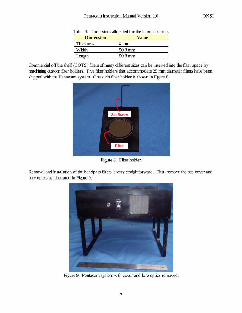
Table 4. Dimensions allocated for the bandpass filter.
50.8 mmLength50.8 mmWidth4 mmThickness
ValueDimension
Commercial off the shelf (COTS) filters of many different sizes can be inserted into the filter space bymachining custom filter holders. Five filter holders that accommodate 25 mm diameter filters have beenshipped with the Pentacam system. One such filter holder is shown in Figure 8.
Filter
Set Screw
Figure 8. Filter holder.
Removal and installation of the bandpass filters is very straightforward. First, remove the top cover andfore optics as illustrated in Figure 9.
Figure 9. Pentacam system with cover and fore optics removed.
Pentacam Instruction Manual Version 1.0 OKSI
7
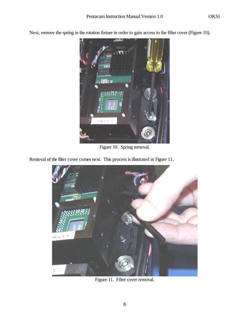
Next, remove the spring in the rotation fixture in order to gain access to the filter cover (Figure 10).
Figure 10. Spring removal.
Removal of the filter cover comes next. This process is illustrated in Figure 11.
Figure 11. Filter cover removal.
Pentacam Instruction Manual Version 1.0 OKSI
8
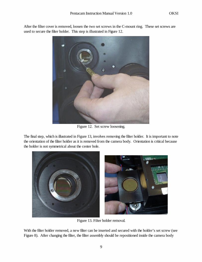
After the filter cover is removed, loosen the two set screws in the C-mount ring. These set screws areused to secure the filter holder. This step is illustrated in Figure 12.
Figure 12. Set screw loosening.
The final step, which is illustrated in Figure 13, involves removing the filter holder. It is important to notethe orientation of the filter holder as it is removed from the camera body. Orientation is critical becausethe holder is not symmetrical about the center hole.
aa
Figure 13. Filter holder removal.
With the filter holder removed, a new filter can be inserted and secured with the holder’s set screw (seeFigure 8). After changing the filter, the filter assembly should be repositioned inside the camera body
Pentacam Instruction Manual Version 1.0 OKSI
9
and secured. It is important make sure that the set screws used to hold the filter holder in place aresecurely tightened because these screws also aid in holding the lens in place.
3 DRIVER INSTALLATION
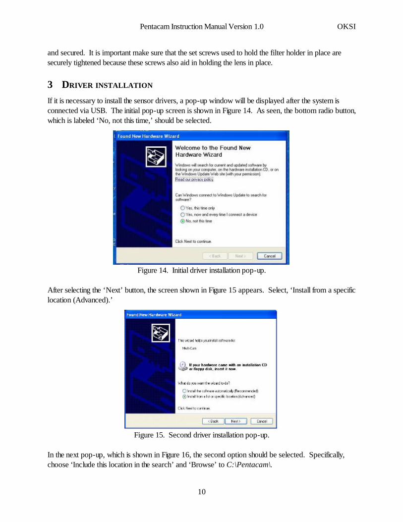
If it is necessary to install the sensor drivers, a pop-up window will be displayed after the system isconnected via USB. The initial pop-up screen is shown in Figure 14. As seen, the bottom radio button,which is labeled ‘No, not this time,’ should be selected.
Figure 14. Initial driver installation pop-up.
After selecting the ‘Next’ button, the screen shown in Figure 15 appears. Select, ‘Install from a specificlocation (Advanced).’
Z
Figure 15. Second driver installation pop-up.
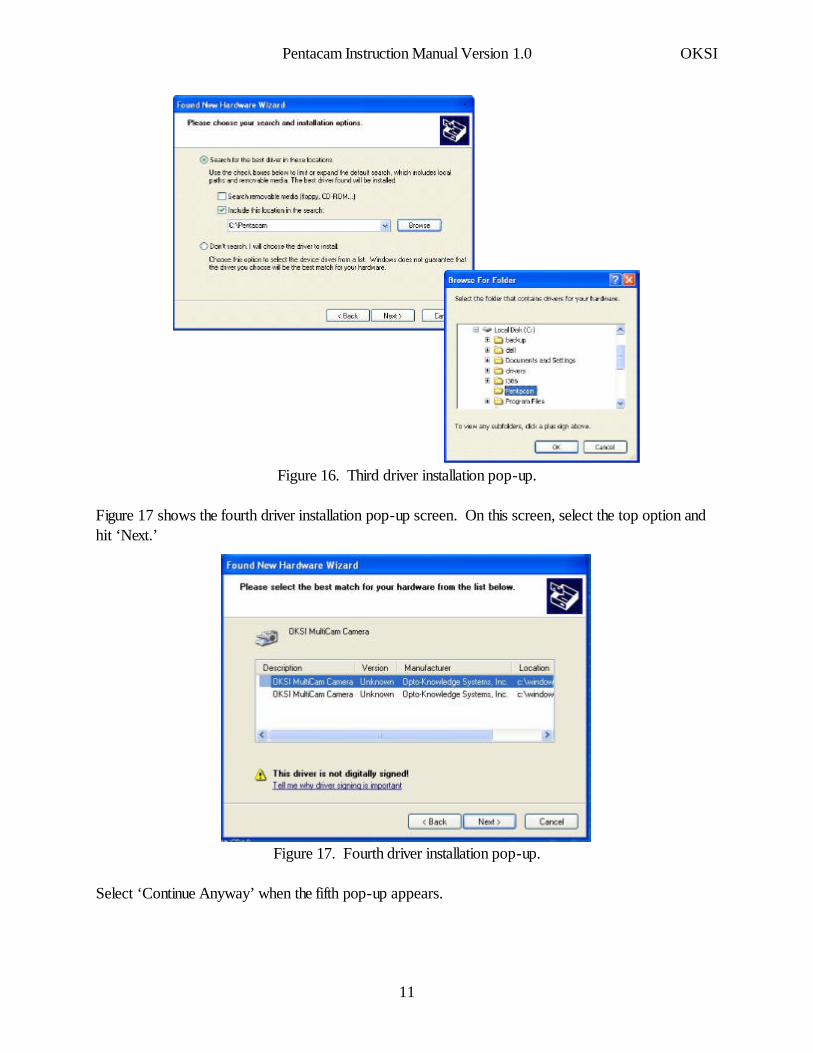
In the next pop-up, which is shown in Figure 16, the second option should be selected. Specifically,choose ‘Include this location in the search’ and ‘Browse’ to C:\Pentacam\.
Pentacam Instruction Manual Version 1.0 OKSI
10
A
Figure 16. Third driver installation pop-up.
Figure 17 shows the fourth driver installation pop-up screen. On this screen, select the top option andhit ‘Next.’
Figure 17. Fourth driver installation pop-up.
Select ‘Continue Anyway’ when the fifth pop-up appears.
Pentacam Instruction Manual Version 1.0 OKSI
11
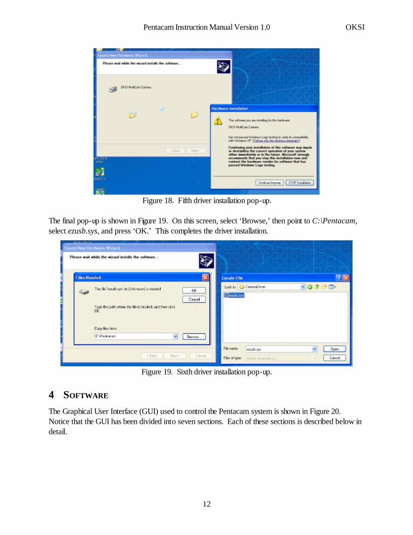
Figure 18. Fifth driver installation pop-up.
The final pop-up is shown in Figure 19. On this screen, select ‘Browse,’ then point to C:\Pentacam,select ezusb.sys, and press ‘OK.’ This completes the driver installation.
Figure 19. Sixth driver installation pop-up.
4 SOFTWARE
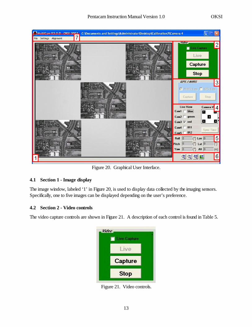
The Graphical User Interface (GUI) used to control the Pentacam system is shown in Figure 20.Notice that the GUI has been divided into seven sections. Each of these sections is described below indetail.
Pentacam Instruction Manual Version 1.0 OKSI
12
.
Figure 20. Graphical User Interface.
4.1 Section 1 - Image display
The image window, labeled ‘1’ in Figure 20, is used to display data collected by the imaging sensors.Specifically, one to five images can be displayed depending on the user’s preference.
4.2 Section 2 - Video controls
The video capture controls are shown in Figure 21. A description of each control is found in Table 5.
.
Figure 21. Video controls.
Pentacam Instruction Manual Version 1.0 OKSI
13
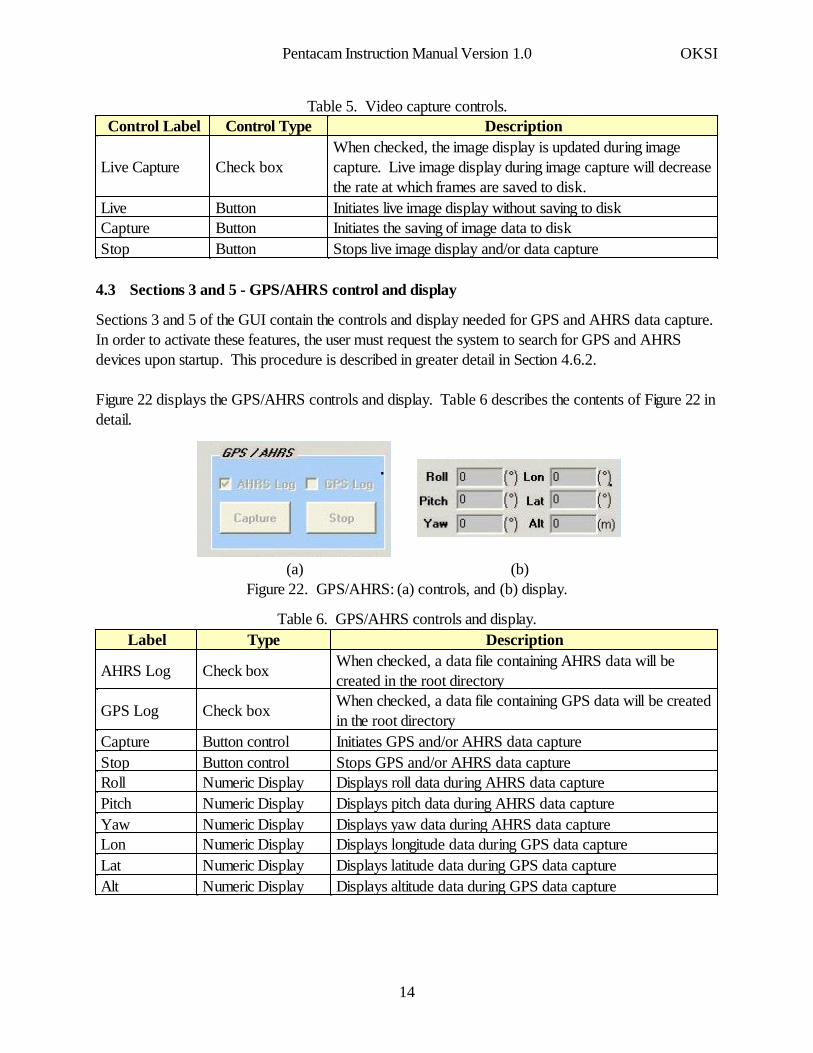
Table 5. Video capture controls.
Stops live image display and/or data captureButtonStopInitiates the saving of image data to diskButtonCaptureInitiates live image display without saving to diskButtonLive
When checked, the image display is updated during imagecapture. Live image display during image capture will decreasethe rate at which frames are saved to disk.
Check boxLive Capture
DescriptionControl TypeControl Label
4.3 Sections 3 and 5 - GPS/AHRS control and display
Sections 3 and 5 of the GUI contain the controls and display needed for GPS and AHRS data capture.In order to activate these features, the user must request the system to search for GPS and AHRSdevices upon startup. This procedure is described in greater detail in Section 4.6.2.
Figure 22 displays the GPS/AHRS controls and display. Table 6 describes the contents of Figure 22 indetail.
(b)(a)
..
Figure 22. GPS/AHRS: (a) controls, and (b) display.
Table 6. GPS/AHRS controls and display.
Displays altitude data during GPS data captureNumeric DisplayAltDisplays latitude data during GPS data captureNumeric DisplayLatDisplays longitude data during GPS data captureNumeric DisplayLonDisplays yaw data during AHRS data captureNumeric DisplayYawDisplays pitch data during AHRS data captureNumeric DisplayPitchDisplays roll data during AHRS data captureNumeric DisplayRollStops GPS and/or AHRS data capture Button controlStopInitiates GPS and/or AHRS data capture Button controlCapture
When checked, a data file containing GPS data will be createdin the root directory
Check box GPS Log
When checked, a data file containing AHRS data will becreated in the root directory
Check box AHRS Log
DescriptionTypeLabel
Pentacam Instruction Manual Version 1.0 OKSI
14
The Pentacam software is configured to work with the AHRS400 made by Crossbow(www.xbow.com). Because different inertial systems have different packet protocols and serialcommands, the Pentacam software does not support other INS devices.
The GPS system used during software testing was the GARMIN GPSMAP76. However, theGPSMAP76 produces standard NMEA packets via RS-232 (4800 baud). Therefore, other GPSsystems that comply to this protocol should work with the Pentacam software.
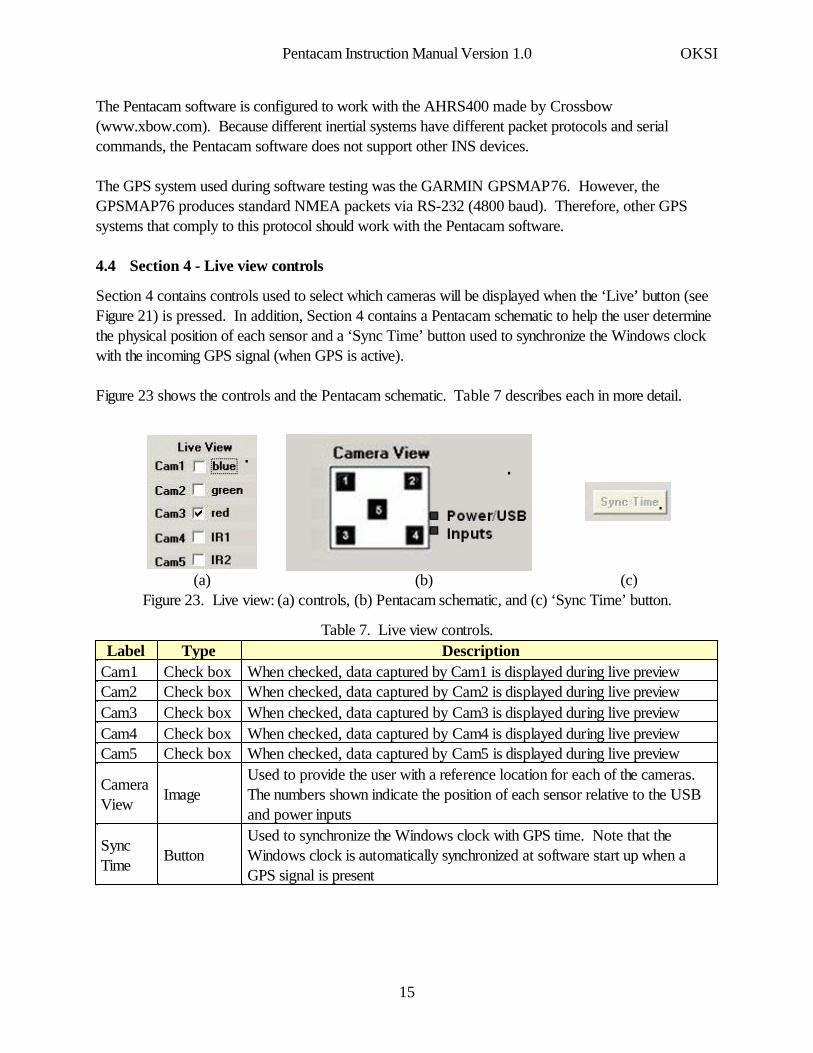
4.4 Section 4 - Live view controls
Section 4 contains controls used to select which cameras will be displayed when the ‘Live’ button (seeFigure 21) is pressed. In addition, Section 4 contains a Pentacam schematic to help the user determinethe physical position of each sensor and a ‘Sync Time’ button used to synchronize the Windows clockwith the incoming GPS signal (when GPS is active).
Figure 23 shows the controls and the Pentacam schematic. Table 7 describes each in more detail.
(c)(b)(a)
...
Figure 23. Live view: (a) controls, (b) Pentacam schematic, and (c) ‘Sync Time’ button.
Table 7. Live view controls.
Used to synchronize the Windows clock with GPS time. Note that theWindows clock is automatically synchronized at software start up when aGPS signal is present
ButtonSyncTime
Used to provide the user with a reference location for each of the cameras.The numbers shown indicate the position of each sensor relative to the USBand power inputs
ImageCameraView
When checked, data captured by Cam5 is displayed during live previewCheck box Cam5When checked, data captured by Cam4 is displayed during live previewCheck box Cam4When checked, data captured by Cam3 is displayed during live previewCheck box Cam3When checked, data captured by Cam2 is displayed during live previewCheck box Cam2When checked, data captured by Cam1 is displayed during live previewCheck box Cam1
DescriptionType Label
Pentacam Instruction Manual Version 1.0 OKSI
15
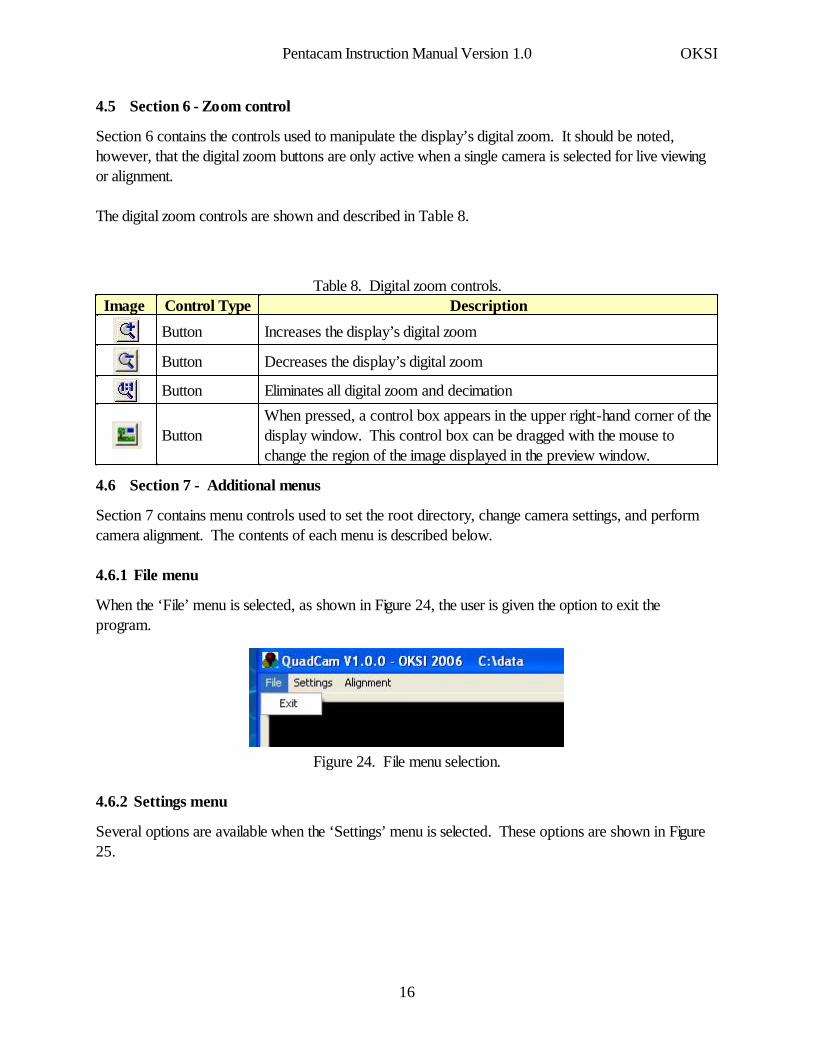
4.5 Section 6 - Zoom control
Section 6 contains the controls used to manipulate the display’s digital zoom. It should be noted,however, that the digital zoom buttons are only active when a single camera is selected for live viewingor alignment.
The digital zoom controls are shown and described in Table 8.
Table 8. Digital zoom controls.
When pressed, a control box appears in the upper right-hand corner of thedisplay window. This control box can be dragged with the mouse tochange the region of the image displayed in the preview window.
Button
Eliminates all digital zoom and decimationButton
Decreases the display’s digital zoomButton
Increases the display’s digital zoomButton
DescriptionControl TypeImage
4.6 Section 7 - Additional menus
Section 7 contains menu controls used to set the root directory, change camera settings, and performcamera alignment. The contents of each menu is described below.
4.6.1 File menu
When the ‘File’ menu is selected, as shown in Figure 24, the user is given the option to exit theprogram.
Figure 24. File menu selection.
4.6.2 Settings menu
Several options are available when the ‘Settings’ menu is selected. These options are shown in Figure25.
Pentacam Instruction Manual Version 1.0 OKSI
16

Figure 25. Settings menu selection.
When ‘Camera Settings’ is selected, a pop-up screen appears. This pop-up screen, which is shown inFigure 26, allows the user to control various aspects of image capture and display. Details associatedwith these controls are listed in Table 9.
blue green red IR1 IR2
Figure 26. Camera Settings pop-up.
Table 9. Camera Setting controls.
Removes the ‘Camera Settings’ pop-up from the screen withoutimplementing the current settings
ButtonCancel
Implements the current settings ButtonOKUsed to select the baud rate of an incoming GPS signalList BoxGPS Baud Rate
When checked, the Pentacam software will look for a GPS deviceduring startup
Check box Use GPS
When checked, the Pentacam software will look for a AHRSdevice during startup
Check box Use AHRS
Determines the number of frames saved to disk after the ‘Capture’button (Figure 21) is pressed
Numeric Capture Frames
Allows the user to enter a name for each camera (this name appearsin Section 4 of the GUI)
String Cam Name
When checked, image data is saved after the ‘Capture’ button(Figure 21) is pressed
Check box Cam Capture
Time, from 1 to 321 ms, that each sensor integrates Numeric Exposure Time
DescriptionControlType
Label
Pentacam Instruction Manual Version 1.0 OKSI
17
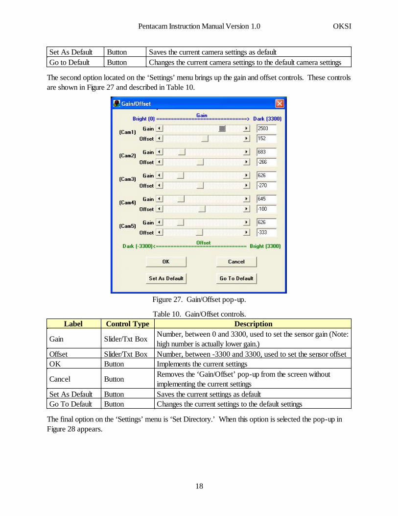
Changes the current camera settings to the default camera settingsButtonGo to DefaultSaves the current camera settings as defaultButtonSet As Default
The second option located on the ‘Settings’ menu brings up the gain and offset controls. These controlsare shown in Figure 27 and described in Table 10.
.
Figure 27. Gain/Offset pop-up.
Table 10. Gain/Offset controls.
Changes the current settings to the default settingsButtonGo To DefaultSaves the current settings as defaultButtonSet As Default
Removes the ‘Gain/Offset’ pop-up from the screen withoutimplementing the current settings
ButtonCancel
Implements the current settings ButtonOKNumber, between -3300 and 3300, used to set the sensor offset Slider/Txt BoxOffset
Number, between 0 and 3300, used to set the sensor gain (Note:high number is actually lower gain.)
Slider/Txt BoxGain
DescriptionControl Type Label
The final option on the ‘Settings’ menu is ‘Set Directory.’ When this option is selected the pop-up inFigure 28 appears.
Pentacam Instruction Manual Version 1.0 OKSI
18
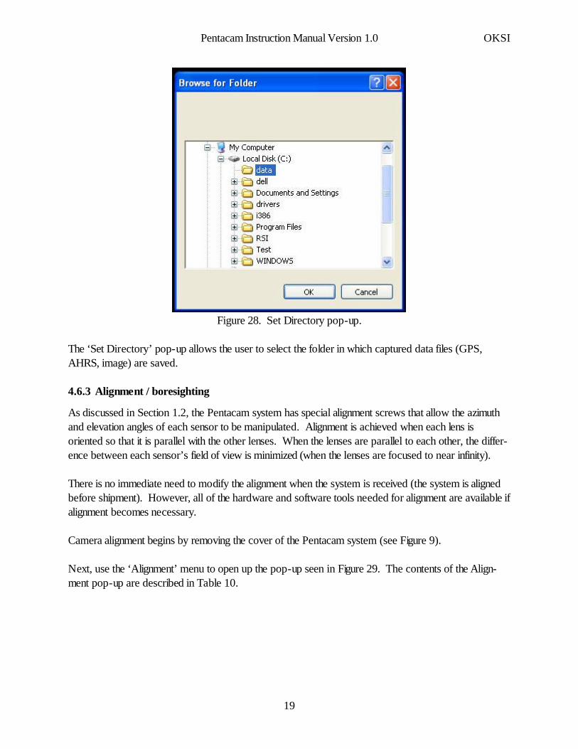
Figure 28. Set Directory pop-up.
The ‘Set Directory’ pop-up allows the user to select the folder in which captured data files (GPS,AHRS, image) are saved.
4.6.3 Alignment / boresighting
As discussed in Section 1.2, the Pentacam system has special alignment screws that allow the azimuthand elevation angles of each sensor to be manipulated. Alignment is achieved when each lens isoriented so that it is parallel with the other lenses. When the lenses are parallel to each other, the differ-ence between each sensor’s field of view is minimized (when the lenses are focused to near infinity).
There is no immediate need to modify the alignment when the system is received (the system is alignedbefore shipment). However, all of the hardware and software tools needed for alignment are available ifalignment becomes necessary.
Camera alignment begins by removing the cover of the Pentacam system (see Figure 9).
Next, use the ‘Alignment’ menu to open up the pop-up seen in Figure 29. The contents of the Align-ment pop-up are described in Table 10.
Pentacam Instruction Manual Version 1.0 OKSI
19
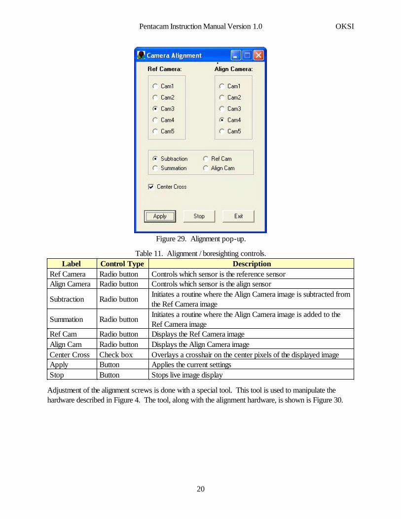
.
Figure 29. Alignment pop-up.
Table 11. Alignment / boresighting controls.
Stops live image displayButtonStopApplies the current settingsButtonApplyOverlays a crosshair on the center pixels of the displayed imageCheck boxCenter CrossDisplays the Align Camera imageRadio buttonAlign CamDisplays the Ref Camera imageRadio buttonRef Cam
Initiates a routine where the Align Camera image is added to theRef Camera image
Radio buttonSummation
Initiates a routine where the Align Camera image is subtracted fromthe Ref Camera image
Radio buttonSubtraction
Controls which sensor is the align sensorRadio buttonAlign CameraControls which sensor is the reference sensorRadio buttonRef Camera
DescriptionControl Type Label
Adjustment of the alignment screws is done with a special tool. This tool is used to manipulate thehardware described in Figure 4. The tool, along with the alignment hardware, is shown is Figure 30.
Pentacam Instruction Manual Version 1.0 OKSI
20
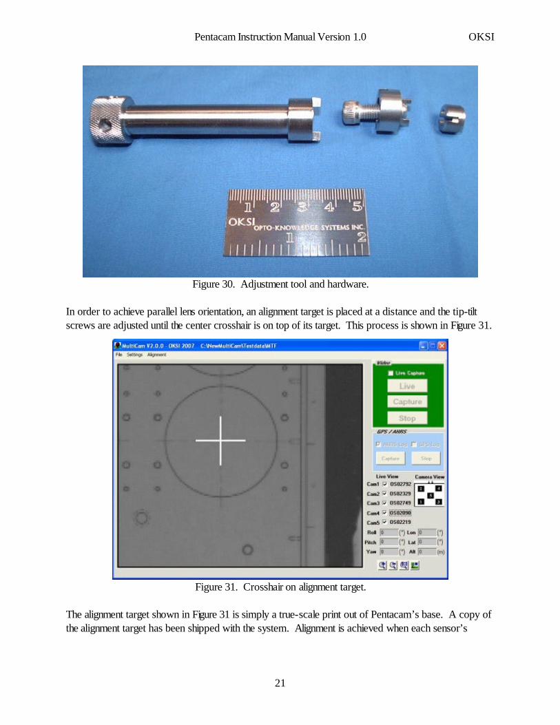
Figure 30. Adjustment tool and hardware.
In order to achieve parallel lens orientation, an alignment target is placed at a distance and the tip-tiltscrews are adjusted until the center crosshair is on top of its target. This process is shown in Figure 31.
A
Figure 31. Crosshair on alignment target.
The alignment target shown in Figure 31 is simply a true-scale print out of Pentacam’s base. A copy ofthe alignment target has been shipped with the system. Alignment is achieved when each sensor’s
Pentacam Instruction Manual Version 1.0 OKSI
21
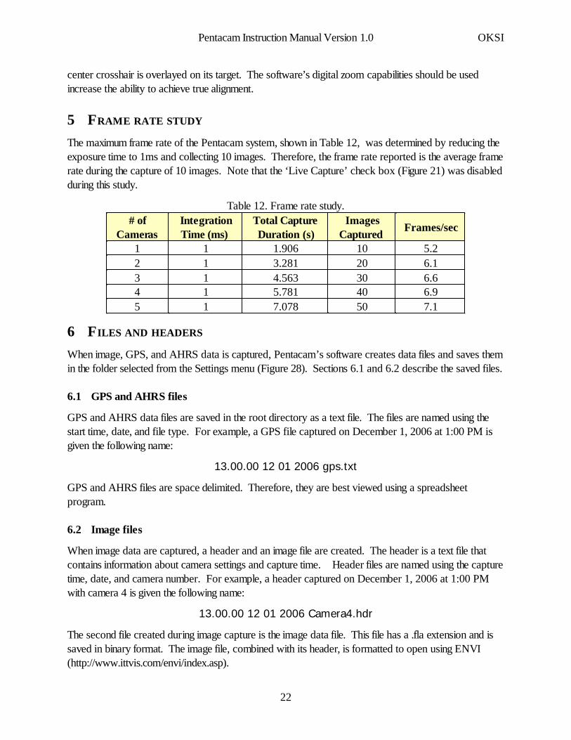
center crosshair is overlayed on its target. The software’s digital zoom capabilities should be usedincrease the ability to achieve true alignment.
5 FRAME RATE STUDY
The maximum frame rate of the Pentacam system, shown in Table 12, was determined by reducing theexposure time to 1ms and collecting 10 images. Therefore, the frame rate reported is the average framerate during the capture of 10 images. Note that the ‘Live Capture’ check box (Figure 21) was disabledduring this study.
Table 12. Frame rate study.
7.1507.078156.9405.781146.6304.563136.1203.281125.2101.90611
Frames/secImages
Captured Total CaptureDuration (s)
IntegrationTime (ms)
# ofCameras
6 FILES AND HEADERS
When image, GPS, and AHRS data is captured, Pentacam’s software creates data files and saves themin the folder selected from the Settings menu (Figure 28). Sections 6.1 and 6.2 describe the saved files.
6.1 GPS and AHRS files
GPS and AHRS data files are saved in the root directory as a text file. The files are named using thestart time, date, and file type. For example, a GPS file captured on December 1, 2006 at 1:00 PM isgiven the following name:
13.00.00 12 01 2006 gps.txt
GPS and AHRS files are space delimited. Therefore, they are best viewed using a spreadsheetprogram.
6.2 Image files
When image data are captured, a header and an image file are created. The header is a text file thatcontains information about camera settings and capture time. Header files are named using the capturetime, date, and camera number. For example, a header captured on December 1, 2006 at 1:00 PMwith camera 4 is given the following name:
13.00.00 12 01 2006 Camera4.hdr
The second file created during image capture is the image data file. This file has a .fla extension and issaved in binary format. The image file, combined with its header, is formatted to open using ENVI(http://www.ittvis.com/envi/index.asp).
Pentacam Instruction Manual Version 1.0 OKSI
22
7 RADIOMETRIC CALIBRATION
Before shipment, each of the five image sensors was radiometrically calibrated using a lamp of knownirradiance. Specifically, Equation 1 was used to calculate the gain needed to convert digital numbers(DNs) into radiometric units. The calibration is valid for specific gain/offset settings of the camera.
[1]DN = DF + G $ L $ ETf/#2
Where DN is digital number, DF is dark field (in DN units), G is gain, ET is exposure time, f/# is thef-number of the fore optics, and L is irradiance at the entrance to the fore optics. Units for L do notmatter as long as they are consistent when performing the calibration and subsequently converting imagedata to radiance.
In general, the terms in the equation, DN, DF, G, and L are matrices represented as a 2D image. TheL matrix has the same value at all elements. ET and f/# are scalars. All these analyses can beperformed as “image” analysis within ENVI.
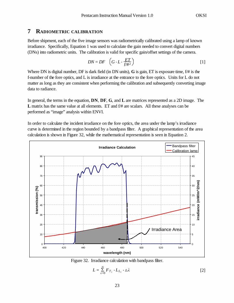
In order to calculate the incident irradiance on the fore optics, the area under the lamp’s irradiancecurve is determined in the region bounded by a bandpass filter. A graphical representation of the areacalculation is shown in Figure 32, while the mathematical representation is seen in Equation 2.
Irradiance Calculation
0
10
20
30
40
50
60
70
80
90
400 420 440 460 480 500 520 540
wavelength (nm)
tran
smis
sio
n (%
)
0
5
10
15
20
25
30
35
40
45
irra
dian
ce (
mW
/m^2
/nm
)
Bandpass filterCalibration lamp
Irradiance Area
Figure 32. Irradiance calculation with bandpass filter.
[2]L = Sk=0
∞FTk $ LLk $ ¿k
Pentacam Instruction Manual Version 1.0 OKSI
23
In Equation 2, FTk is the filter transmission, LLk is the irradiance of the calibration lamp, and Dk is thewavelength step size used for numerical integration.
Once a gain image, G, has been calculated using Equations 1 and 2 for some f/# and ET, the calibrationequation can be generalized to account of any f/# and ET. The general calibration equation is shown inEquation 3 (DF image should be captured under field conditions, since the DF depends ontemperature).
[3]DN = DF + (G $ f/#R2 $ ETR $ L)
Where :
[5]ETR = ETnET0
[4]f/#R =f/#0f/#n
The subscript values in Equations 4 and 5 distinguish between the reference f/# and ET (given a value of0) and the f/# and ET for measurement n.
Gain images, calculated using Equation 1, for each Pentacam camera (with its specific bandpass filter inplace) have been shipped with the system (on the CD). The calibration f/# and exposure time (f/#0 andET0) have already been accounted for in the gain images, and therefore, irradiance at the entrance to thefore optics can be determined by plugging in the values for DN, DF, f/#n, and ETn into Equation 6.
[6]L =(DN − DF) $ f/#n
2
G $ ETn
Section 11.2 describes an ENVI routine shipped with the Pentacam system that can be used to convertraw images (DN units) to radiometric images (radiometric units). However, all of the calculations canbe done in ENVI once the DN, DF, and G images are saved.
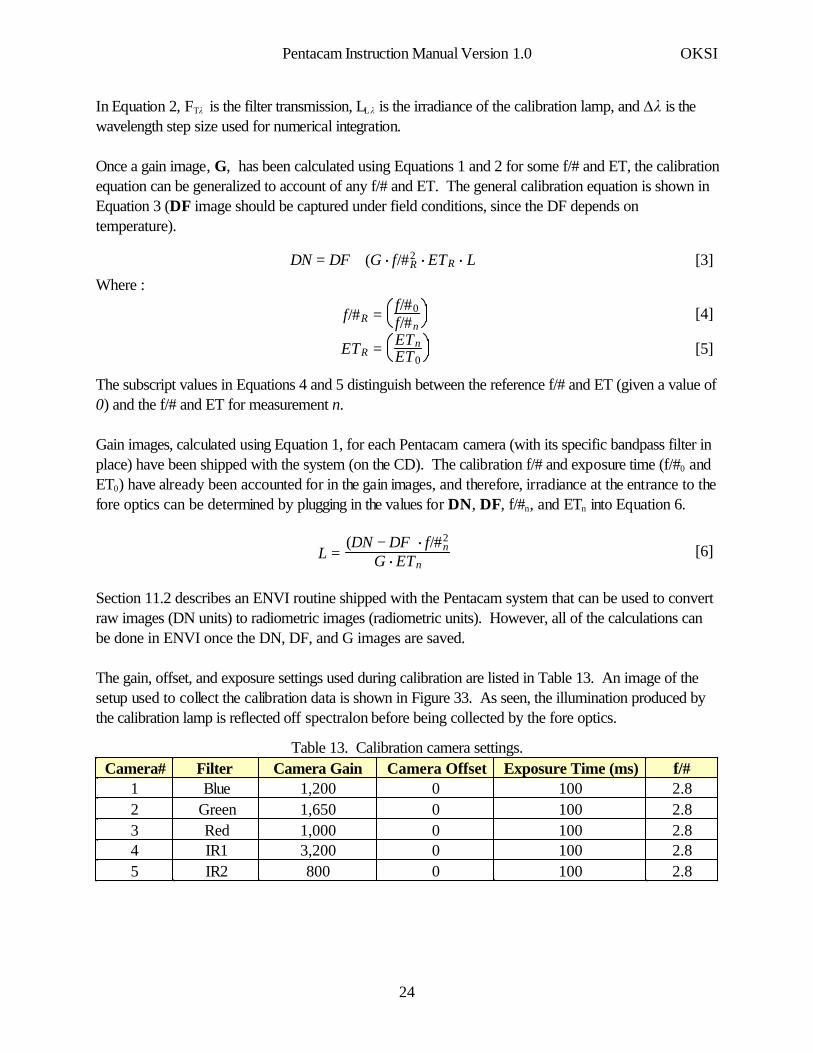
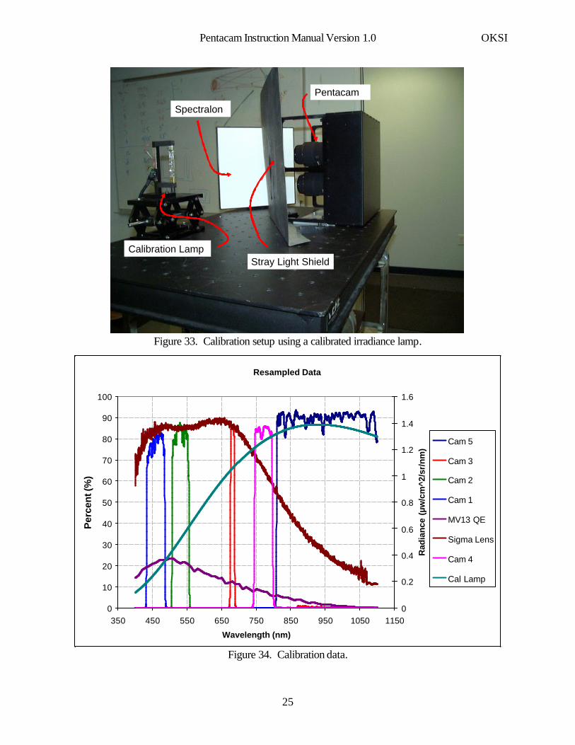
The gain, offset, and exposure settings used during calibration are listed in Table 13. An image of thesetup used to collect the calibration data is shown in Figure 33. As seen, the illumination produced bythe calibration lamp is reflected off spectralon before being collected by the fore optics.
Table 13. Calibration camera settings.
2.81000800IR252.810003,200IR142.810001,000Red32.810001,650Green22.810001,200Blue1f/#Exposure Time (ms)Camera OffsetCamera GainFilter Camera#
Pentacam Instruction Manual Version 1.0 OKSI
24
Calibration Lamp
Spectralon
Stray Light Shield
Pentacam
Figure 33. Calibration setup using a calibrated irradiance lamp.
Resampled Data
0
10
20
30
40
50
60
70
80
90
100
350 450 550 650 750 850 950 1050 1150
Wavelength (nm)
Per
cen
t (%
)
0
0.2
0.4
0.6
0.8
1
1.2
1.4
1.6
Rad
ian
ce (
µw/c
m^2
/sr/
nm
)
Cam 5
Cam 3
Cam 2
Cam 1
MV13 QE
Sigma Lens
Cam 4
Cal Lamp
Figure 34. Calibration data.
Pentacam Instruction Manual Version 1.0 OKSI
25
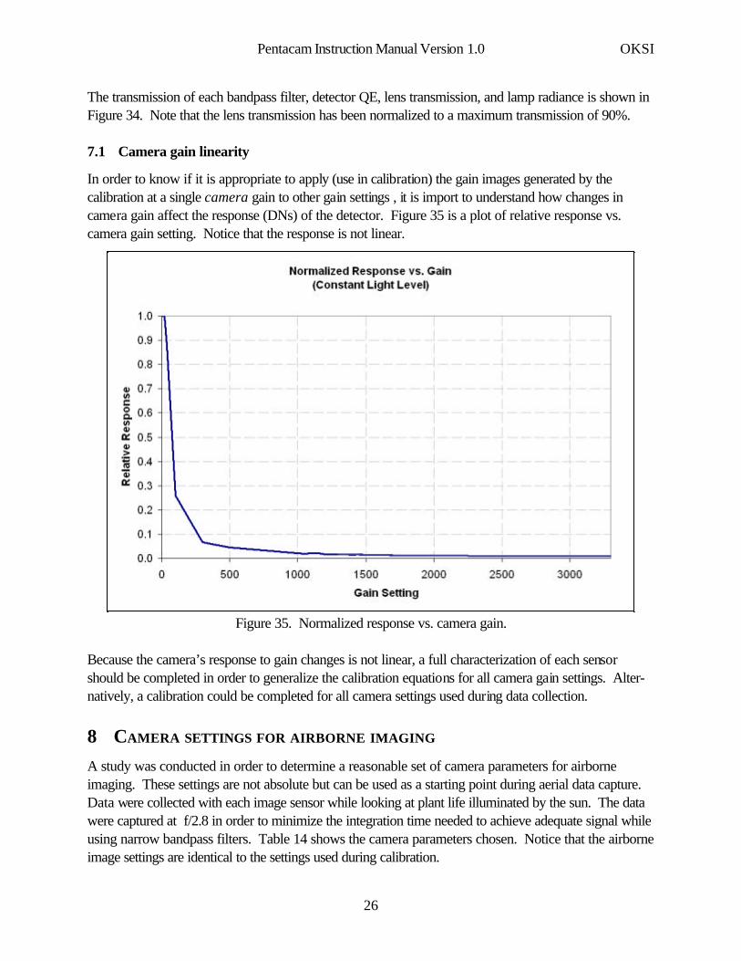
The transmission of each bandpass filter, detector QE, lens transmission, and lamp radiance is shown inFigure 34. Note that the lens transmission has been normalized to a maximum transmission of 90%.
7.1 Camera gain linearity
In order to know if it is appropriate to apply (use in calibration) the gain images generated by thecalibration at a single camera gain to other gain settings , it is import to understand how changes incamera gain affect the response (DNs) of the detector. Figure 35 is a plot of relative response vs.camera gain setting. Notice that the response is not linear.
Figure 35. Normalized response vs. camera gain.
Because the camera’s response to gain changes is not linear, a full characterization of each sensorshould be completed in order to generalize the calibration equations for all camera gain settings. Alter-natively, a calibration could be completed for all camera settings used during data collection.
8 CAMERA SETTINGS FOR AIRBORNE IMAGING
A study was conducted in order to determine a reasonable set of camera parameters for airborneimaging. These settings are not absolute but can be used as a starting point during aerial data capture.Data were collected with each image sensor while looking at plant life illuminated by the sun. The datawere captured at f/2.8 in order to minimize the integration time needed to achieve adequate signal whileusing narrow bandpass filters. Table 14 shows the camera parameters chosen. Notice that the airborneimage settings are identical to the settings used during calibration.
Pentacam Instruction Manual Version 1.0 OKSI
26
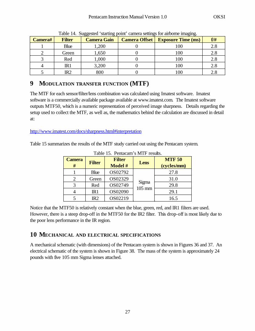
Table 14. Suggested ‘starting point’ camera settings for airborne imaging.
2.81000800IR252.810003,200IR142.810001,000Red32.810001,650Green22.810001,200Blue1f/#Exposure Time (ms)Camera OffsetCamera GainFilter Camera#
9 MODULATION TRANSFER FUNCTION (MTF)The MTF for each sensor/filter/lens combination was calculated using Imatest software. Imatestsoftware is a commercially available package available at www.imatest.com. The Imatest softwareoutputs MTF50, which is a numeric representation of perceived image sharpness. Details regarding thesetup used to collect the MTF, as well as, the mathematics behind the calculation are discussed in detailat:
http://www.imatest.com/docs/sharpness.html#interpretation
Table 15 summarizes the results of the MTF study carried out using the Pentacam system.
Table 15. Pentacam’s MTF results.
16.5OS02219IR2529.1OS02090IR1429.8OS02749Red331.0OS02329Green227.8
Sigma105 mm
OS02792Blue1
MTF 50(cycles/mm)
LensFilter
Model #Filter
Camera#
Notice that the MTF50 is relatively constant when the blue, green, red, and IR1 filters are used.However, there is a steep drop-off in the MTF50 for the IR2 filter. This drop-off is most likely due tothe poor lens performance in the IR region.
10 MECHANICAL AND ELECTRICAL SPECIFICATIONS
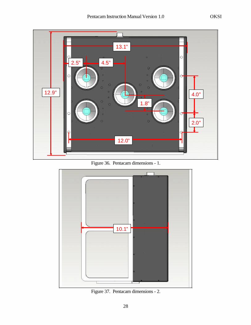
A mechanical schematic (with dimensions) of the Pentacam system is shown in Figures 36 and 37. Anelectrical schematic of the system is shown in Figure 38. The mass of the system is approximately 24pounds with five 105 mm Sigma lenses attached.
Pentacam Instruction Manual Version 1.0 OKSI
27
12.0”
12.9”
13.1”
2.0”
4.0”
2.5” 4.5”
1.8”
Figure 36. Pentacam dimensions - 1.
10.1”
Figure 37. Pentacam dimensions - 2.
Pentacam Instruction Manual Version 1.0 OKSI
28
Cam1
Cam2
Cam3
Cam4
Cam5
USB
+5VDC
GND
TRIGGER
USB Hub
Fan
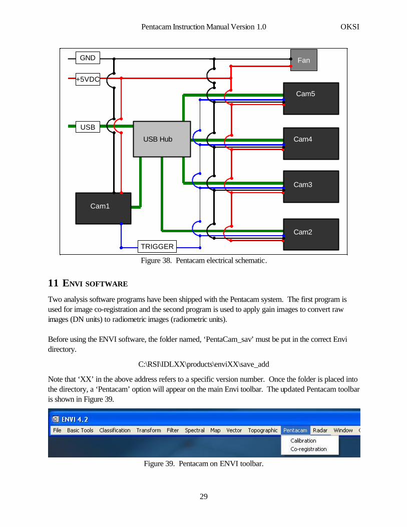
Figure 38. Pentacam electrical schematic.
11 ENVI SOFTWARE
Two analysis software programs have been shipped with the Pentacam system. The first program isused for image co-registration and the second program is used to apply gain images to convert rawimages (DN units) to radiometric images (radiometric units).
Before using the ENVI software, the folder named, ‘PentaCam_sav’ must be put in the correct Envidirectory.
C:\RSI\IDLXX\products\enviXX\save_add
Note that ‘XX’ in the above address refers to a specific version number. Once the folder is placed intothe directory, a ‘Pentacam’ option will appear on the main Envi toolbar. The updated Pentacam toolbaris shown in Figure 39.
Figure 39. Pentacam on ENVI toolbar.
Pentacam Instruction Manual Version 1.0 OKSI
29

11.1 Co-registration software
The objective of the co-registration software is to spatially warp one or more images to match a refer-ence image. Warping reduces the spatial differences between images that have not been removed byhardware alignment, and correct for paraxial shift due to the displacement of the lenses. However,parallax correction is best applied at infinity, and can not be applied to image with objects at differentdepth of field.
After ‘Co-registration’ has been selected on the Envi toolbar (Figure 39), the pop-up screen shown inFigure 40 appears.
.
Figure 40. Reference cube pop-up.
The pop-up shown in Figure 40 asks the user to select a reference file. The reference file is a timeseries of images, i.e., an image cube (.fla extension) produced by a single Pentacam sensor. The imagesin the reference cube are not warped by the co-registration software. Instead, it is used as the ‘master’image to which all other images are matched. Typically, the center sensor (Cam5) is used as the refer-ence sensor due to its physical location. After the reference cube has been selected, the softwareprompts the user to select up to four additional time-series for co-registration. If less than four aredesired the user can stop the analysis by selecting ‘Cancel.’
The co-registration, not only co-registers the time sequence of images, but also parses the time-sequence and creates multispectral image cubes (of time-synchronized images). Therefore the output of
Pentacam Instruction Manual Version 1.0 OKSI
30
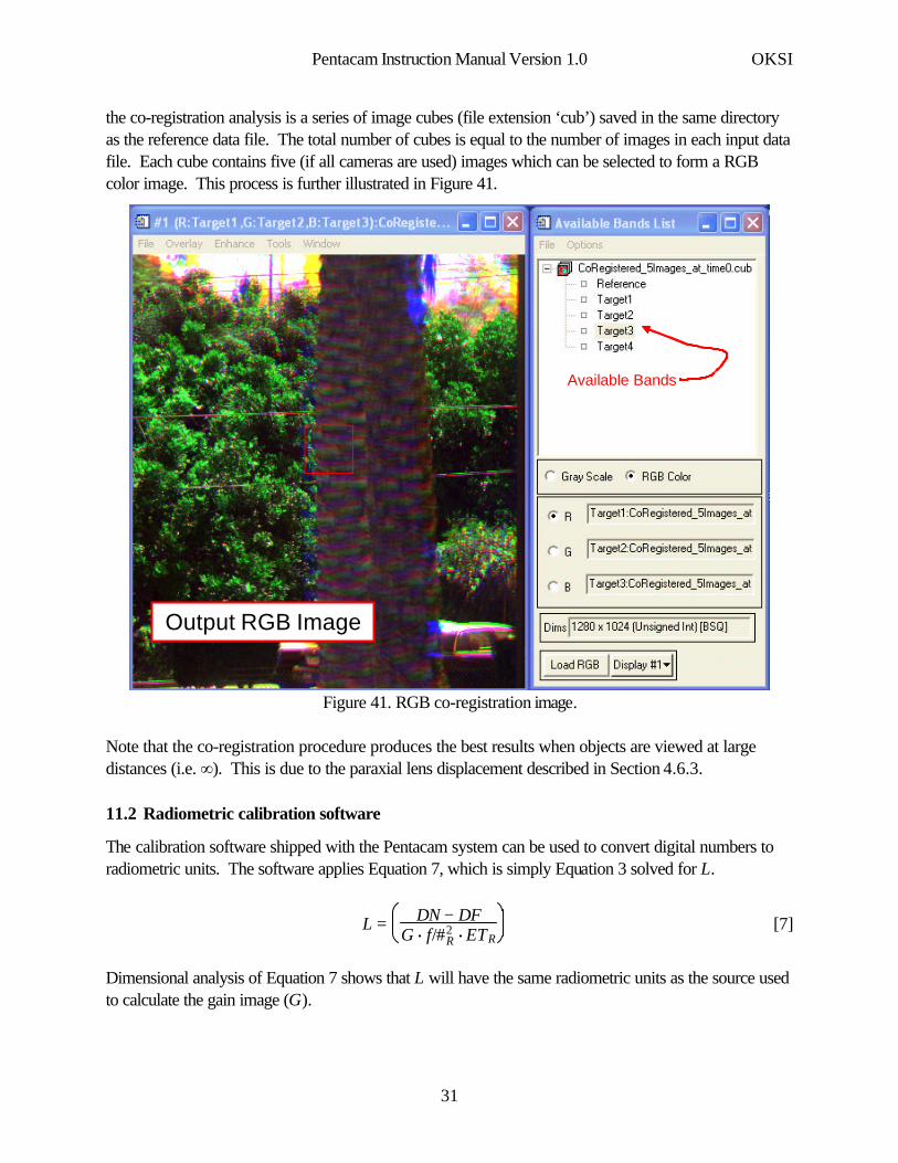
the co-registration analysis is a series of image cubes (file extension ‘cub’) saved in the same directoryas the reference data file. The total number of cubes is equal to the number of images in each input datafile. Each cube contains five (if all cameras are used) images which can be selected to form a RGBcolor image. This process is further illustrated in Figure 41.
.
Available Bands
Output RGB Image
Figure 41. RGB co-registration image.
Note that the co-registration procedure produces the best results when objects are viewed at largedistances (i.e. ∞). This is due to the paraxial lens displacement described in Section 4.6.3.
11.2 Radiometric calibration software
The calibration software shipped with the Pentacam system can be used to convert digital numbers toradiometric units. The software applies Equation 7, which is simply Equation 3 solved for L.
[7]L = DN − DFG $ f/#R
2 $ ETR
Dimensional analysis of Equation 7 shows that L will have the same radiometric units as the source usedto calculate the gain image (G).
Pentacam Instruction Manual Version 1.0 OKSI
31

The radiometric calibration software is started by selecting ‘Calibration’ under the Pentacam heading onthe Envi toolbar (see Figure 39). Once started, the pop-up shown in Figure 42 appears asking the userto enter the exposure time and f/# of the image undergoing calibration.
.
Figure 42. Exposure time and f/# inputs.
The exposure time and f/# entered represent ETn and f/#n as described in Equations 4 and 5.
Once the user has entered the appropriate exposure time and f/#, the software prompts the user to enteran image cube with units in DNs. The pop-up used to facilitate this process is shown in Figure 43.
.
Figure 43. DN pop-up.
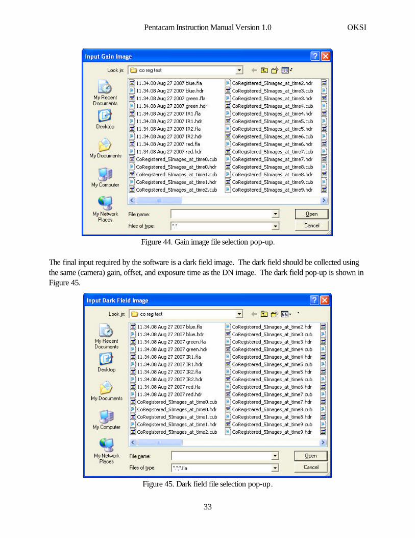
Next, the software requires the user to input a gain image. The gain image is generated by using asource of know radiance. Gain images have been shipped with the system (on the CD) but it is goodpractice to recalibrate (calculate new gain images) on a regular basis or if any of the optical hardwarechanges (lens, filters, etc.). The gain image pop-up is shown in Figure 44.
Pentacam Instruction Manual Version 1.0 OKSI
32
.
Figure 44. Gain image file selection pop-up.
The final input required by the software is a dark field image. The dark field should be collected usingthe same (camera) gain, offset, and exposure time as the DN image. The dark field pop-up is shown inFigure 45.
.
Figure 45. Dark field file selection pop-up.
Pentacam Instruction Manual Version 1.0 OKSI
33
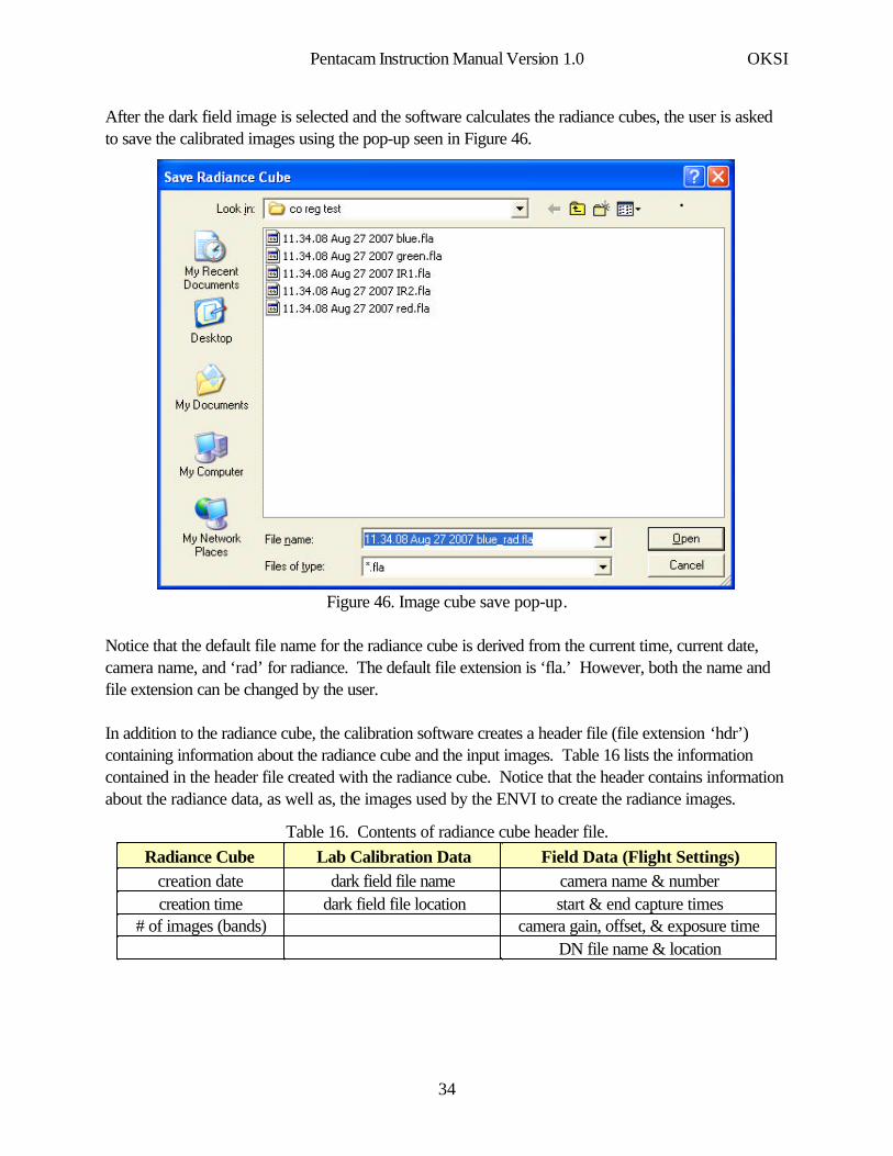
After the dark field image is selected and the software calculates the radiance cubes, the user is askedto save the calibrated images using the pop-up seen in Figure 46.
.
Figure 46. Image cube save pop-up.
Notice that the default file name for the radiance cube is derived from the current time, current date,camera name, and ‘rad’ for radiance. The default file extension is ‘fla.’ However, both the name andfile extension can be changed by the user.
In addition to the radiance cube, the calibration software creates a header file (file extension ‘hdr’)containing information about the radiance cube and the input images. Table 16 lists the informationcontained in the header file created with the radiance cube. Notice that the header contains informationabout the radiance data, as well as, the images used by the ENVI to create the radiance images.
Table 16. Contents of radiance cube header file.
DN file name & locationcamera gain, offset, & exposure time# of images (bands)
start & end capture timesdark field file locationcreation timecamera name & numberdark field file namecreation date
Field Data (Flight Settings)Lab Calibration DataRadiance Cube
Pentacam Instruction Manual Version 1.0 OKSI
34

12 INSTALLING THE PENTACAM SOFTWARE ON ADDITIONAL COMPUTERS
The Pentacam software is fully installed and operational on the laptop shipped with the system.However, it is possible to install the software on additional computers.
Installing the software is straightforward. The CD shipped with the system contains a folder called‘Pentacam Software.’ The contents of this folder contain all of the necessary components needed torun the software, including the camera driver. Therefore, all the user must do to use the software iscopy the ‘Pentacam Software’ folder to the C drive on the new computer. After the software is copiedand the system is connected via USB, the user must install the drivers using the process outline inSection 3
.
Pentacam Instruction Manual Version 1.0 OKSI
35
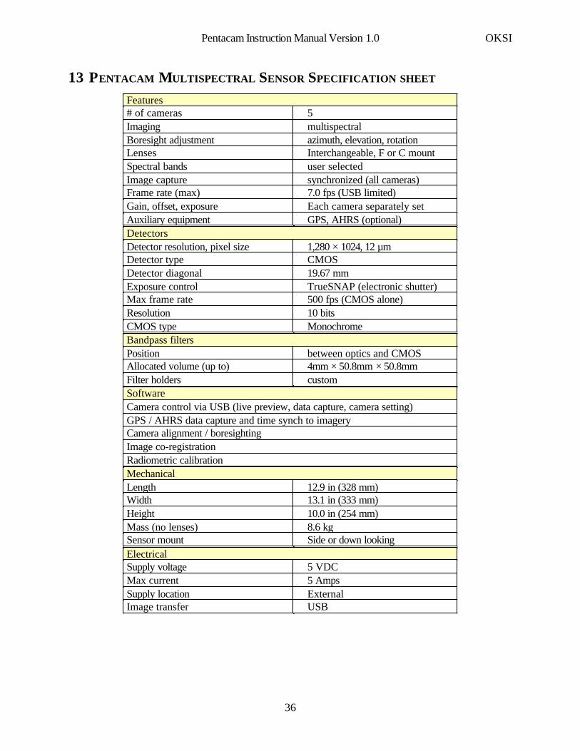
13 PENTACAM MULTISPECTRAL SENSOR SPECIFICATION SHEET
GPS, AHRS (optional)Auxiliary equipmentEach camera separately setGain, offset, exposure7.0 fps (USB limited)Frame rate (max)synchronized (all cameras)Image captureuser selectedSpectral bandsInterchangeable, F or C mountLensesazimuth, elevation, rotationBoresight adjustmentmultispectralImaging5# of cameras
Features
MonochromeCMOS type10 bits Resolution500 fps (CMOS alone)Max frame rate TrueSNAP (electronic shutter)Exposure control19.67 mmDetector diagonalCMOSDetector type1,280 × 1024, 12 µmDetector resolution, pixel size
Detectors
customFilter holders4mm × 50.8mm × 50.8mm Allocated volume (up to)between optics and CMOSPosition
Bandpass filters
Radiometric calibrationImage co-registrationCamera alignment / boresightingGPS / AHRS data capture and time synch to imageryCamera control via USB (live preview, data capture, camera setting)Software
Side or down lookingSensor mount8.6 kgMass (no lenses)10.0 in (254 mm)Height13.1 in (333 mm)Width12.9 in (328 mm)Length
Mechanical
USBImage transferExternalSupply location5 AmpsMax current 5 VDCSupply voltage
Electrical
Pentacam Instruction Manual Version 1.0 OKSI
36