Embed Size (px)
Citation preview
CONITELProtocol Definition
Revision: 2.0218/7/02
CONTENTS
115.6.9 Function 9 - Code 8 . . . . . . . . . . . . . . . . . . . . . . . . . . . . . . . . . . . . . . . . . . . . . . . . . . . .
115.6.8 Function 9 - Code 7 . . . . . . . . . . . . . . . . . . . . . . . . . . . . . . . . . . . . . . . . . . . . . . . . . . . .
115.6.7 Function 9 - Code 6 . . . . . . . . . . . . . . . . . . . . . . . . . . . . . . . . . . . . . . . . . . . . . . . . . . . .
115.6.6 Function 9 - Code 5 . . . . . . . . . . . . . . . . . . . . . . . . . . . . . . . . . . . . . . . . . . . . . . . . . . . .
105.6.5 Function 9 - Code 4 . . . . . . . . . . . . . . . . . . . . . . . . . . . . . . . . . . . . . . . . . . . . . . . . . . . .
105.6.4 Function 9 - Code 3 . . . . . . . . . . . . . . . . . . . . . . . . . . . . . . . . . . . . . . . . . . . . . . . . . . . .
105.6.3 Function 9 - Code 2 . . . . . . . . . . . . . . . . . . . . . . . . . . . . . . . . . . . . . . . . . . . . . . . . . . . .
105.6.2 Function 9 - Code 1 . . . . . . . . . . . . . . . . . . . . . . . . . . . . . . . . . . . . . . . . . . . . . . . . . . . .
105.6.1 Function 9 - Code 0 . . . . . . . . . . . . . . . . . . . . . . . . . . . . . . . . . . . . . . . . . . . . . . . . . . . .
105.6 Master Station Request - Function 9 . . . . . . . . . . . . . . . . . . . . . . . . . . . . . . . . . . . . . . . . .
95.5 Reset RTU - Function 8 . . . . . . . . . . . . . . . . . . . . . . . . . . . . . . . . . . . . . . . . . . . . . . . . . . . . . .
95.4 Setpoint A and Setpoint B - Functions 3 and 5 . . . . . . . . . . . . . . . . . . . . . . . . . . . . . . . .
85.3 Trip and Close - Functions 2 and 4 . . . . . . . . . . . . . . . . . . . . . . . . . . . . . . . . . . . . . . . . . . .
75.2 Execute Command - Function 1 . . . . . . . . . . . . . . . . . . . . . . . . . . . . . . . . . . . . . . . . . . . . . .
75.1 Scan Data - Function 0 . . . . . . . . . . . . . . . . . . . . . . . . . . . . . . . . . . . . . . . . . . . . . . . . . . . . . .
65 Conitel Functions . . . . . . . . . . . . . . . . . . . . . . . . . . . . . . . . . . . . . . . . . . . . . . . . . . . . . . . . . . . . . . . .
54.1 BCH Code - Calculation Example . . . . . . . . . . . . . . . . . . . . . . . . . . . . . . . . . . . . . . . . . . . . .
54 BCH Code . . . . . . . . . . . . . . . . . . . . . . . . . . . . . . . . . . . . . . . . . . . . . . . . . . . . . . . . . . . . . . . . . . . . . . . .
43.6 EOM Bit . . . . . . . . . . . . . . . . . . . . . . . . . . . . . . . . . . . . . . . . . . . . . . . . . . . . . . . . . . . . . . . . . . . . . .
43.5 BCH Code . . . . . . . . . . . . . . . . . . . . . . . . . . . . . . . . . . . . . . . . . . . . . . . . . . . . . . . . . . . . . . . . . . .
43.4 "B" Bit . . . . . . . . . . . . . . . . . . . . . . . . . . . . . . . . . . . . . . . . . . . . . . . . . . . . . . . . . . . . . . . . . . . . . . . .
43.3 "B" Section . . . . . . . . . . . . . . . . . . . . . . . . . . . . . . . . . . . . . . . . . . . . . . . . . . . . . . . . . . . . . . . . . . .
43.2 "A" Bit . . . . . . . . . . . . . . . . . . . . . . . . . . . . . . . . . . . . . . . . . . . . . . . . . . . . . . . . . . . . . . . . . . . . . . . .
43.1.3 Group . . . . . . . . . . . . . . . . . . . . . . . . . . . . . . . . . . . . . . . . . . . . . . . . . . . . . . . . . . . . . . . . . . .
43.1.2 Station . . . . . . . . . . . . . . . . . . . . . . . . . . . . . . . . . . . . . . . . . . . . . . . . . . . . . . . . . . . . . . . . . .
43.1.1 Function . . . . . . . . . . . . . . . . . . . . . . . . . . . . . . . . . . . . . . . . . . . . . . . . . . . . . . . . . . . . . . . .
33.1 "A" Section . . . . . . . . . . . . . . . . . . . . . . . . . . . . . . . . . . . . . . . . . . . . . . . . . . . . . . . . . . . . . . . . . . .
33 Message Block Format . . . . . . . . . . . . . . . . . . . . . . . . . . . . . . . . . . . . . . . . . . . . . . . . . . . . . . . . . . .
22.4 Hardware Standard . . . . . . . . . . . . . . . . . . . . . . . . . . . . . . . . . . . . . . . . . . . . . . . . . . . . . . . . . .
22.3.2 Data Types Usually Supported . . . . . . . . . . . . . . . . . . . . . . . . . . . . . . . . . . . . . . . . . .
22.3.1 Functions Usually Supported . . . . . . . . . . . . . . . . . . . . . . . . . . . . . . . . . . . . . . . . . . . .
22.3 Third Party Implementations . . . . . . . . . . . . . . . . . . . . . . . . . . . . . . . . . . . . . . . . . . . . . . . . . .
12.2 Main Disadvantages . . . . . . . . . . . . . . . . . . . . . . . . . . . . . . . . . . . . . . . . . . . . . . . . . . . . . . . . . .
12.1 Main Advantages . . . . . . . . . . . . . . . . . . . . . . . . . . . . . . . . . . . . . . . . . . . . . . . . . . . . . . . . . . . . .
12 General Description . . . . . . . . . . . . . . . . . . . . . . . . . . . . . . . . . . . . . . . . . . . . . . . . . . . . . . . . . . . . . .
11.1 Document Revision Summary . . . . . . . . . . . . . . . . . . . . . . . . . . . . . . . . . . . . . . . . . . . . . . . .
11 Overview . . . . . . . . . . . . . . . . . . . . . . . . . . . . . . . . . . . . . . . . . . . . . . . . . . . . . . . . . . . . . . . . . . . . . . . . . .
i
206.13 Remote Status Bits . . . . . . . . . . . . . . . . . . . . . . . . . . . . . . . . . . . . . . . . . . . . . . . . . . . . . . . . .
206.12 1 to 5 Digit BCD . . . . . . . . . . . . . . . . . . . . . . . . . . . . . . . . . . . . . . . . . . . . . . . . . . . . . . . . . . . .
206.11 Bipolar Analogue . . . . . . . . . . . . . . . . . . . . . . . . . . . . . . . . . . . . . . . . . . . . . . . . . . . . . . . . . .
206.10 Twenty-Four-bit Accumulator . . . . . . . . . . . . . . . . . . . . . . . . . . . . . . . . . . . . . . . . . . . . . . .
196.9 Twelve-bit Accumulator . . . . . . . . . . . . . . . . . . . . . . . . . . . . . . . . . . . . . . . . . . . . . . . . . . . . . .
196.8 Two-bit MCD Type C . . . . . . . . . . . . . . . . . . . . . . . . . . . . . . . . . . . . . . . . . . . . . . . . . . . . . . . .
196.7 Two-bit MCD Type B . . . . . . . . . . . . . . . . . . . . . . . . . . . . . . . . . . . . . . . . . . . . . . . . . . . . . . . .
196.6 Two-bit MCD Type A . . . . . . . . . . . . . . . . . . . . . . . . . . . . . . . . . . . . . . . . . . . . . . . . . . . . . . . .
196.5 One-bit MCD Type C . . . . . . . . . . . . . . . . . . . . . . . . . . . . . . . . . . . . . . . . . . . . . . . . . . . . . . . .
196.4 One-bit MCD Type B . . . . . . . . . . . . . . . . . . . . . . . . . . . . . . . . . . . . . . . . . . . . . . . . . . . . . . .
196.3 One-bit MCD Type A . . . . . . . . . . . . . . . . . . . . . . . . . . . . . . . . . . . . . . . . . . . . . . . . . . . . . . . .
196.2 Two-bit Status . . . . . . . . . . . . . . . . . . . . . . . . . . . . . . . . . . . . . . . . . . . . . . . . . . . . . . . . . . . . . . .
196.1 One-bit Status . . . . . . . . . . . . . . . . . . . . . . . . . . . . . . . . . . . . . . . . . . . . . . . . . . . . . . . . . . . . . . .
196 Data Types . . . . . . . . . . . . . . . . . . . . . . . . . . . . . . . . . . . . . . . . . . . . . . . . . . . . . . . . . . . . . . . . . . . . . .
185.9 Freeze and Scan Accumulators ( and reset ) - Functions E and F . . . . . . . . . . . .
175.8 Unit Raise/Lower - Function D . . . . . . . . . . . . . . . . . . . . . . . . . . . . . . . . . . . . . . . . . . . . . . .
155.7 New and Repeat SOE Events - Functions A and B . . . . . . . . . . . . . . . . . . . . . . . . . . .
145.6.16 Function 9 - Code F . . . . . . . . . . . . . . . . . . . . . . . . . . . . . . . . . . . . . . . . . . . . . . . . . .
145.6.15 Function 9 - Code E . . . . . . . . . . . . . . . . . . . . . . . . . . . . . . . . . . . . . . . . . . . . . . . . . .
145.6.14 Function 9 - Code D . . . . . . . . . . . . . . . . . . . . . . . . . . . . . . . . . . . . . . . . . . . . . . . . . .
135.6.13 Function 9 - Code C . . . . . . . . . . . . . . . . . . . . . . . . . . . . . . . . . . . . . . . . . . . . . . . . . .
135.6.12 Function 9 - Code B . . . . . . . . . . . . . . . . . . . . . . . . . . . . . . . . . . . . . . . . . . . . . . . . . .
135.6.11 Function 9 - Code A . . . . . . . . . . . . . . . . . . . . . . . . . . . . . . . . . . . . . . . . . . . . . . . . . .
125.6.10 Function 9 - Code 9 . . . . . . . . . . . . . . . . . . . . . . . . . . . . . . . . . . . . . . . . . . . . . . . . . . .
1. Overview This document attempts to define the Conitel protocol, used for SCADA and telemetry applications. Theinformation contained here has been pieced together from various sources. As a result, accuracy andcompleteness cannot be guaranteed. This document was not produced by Leeds & Northrup, and has noofficial standing.
This document is Copyright © 1993-2002 C.Muirden.
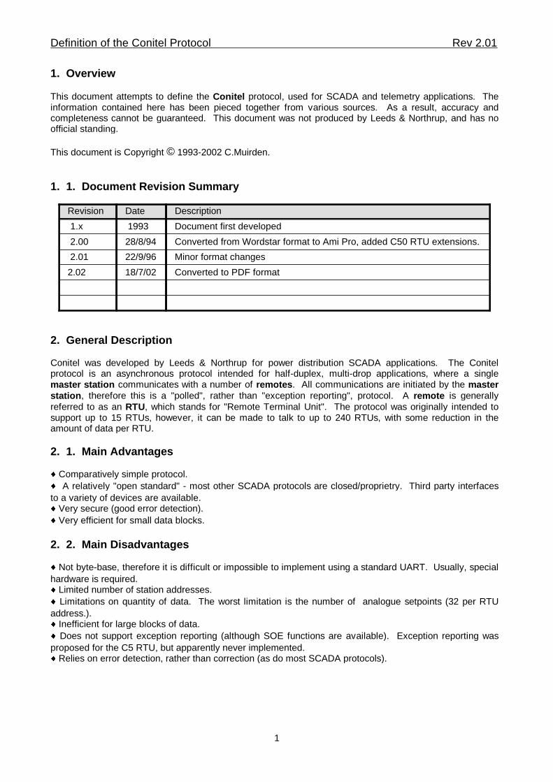
1. 1. Document Revision Summary
Converted to PDF format18/7/022.02
Minor format changes22/9/96 2.01
Converted from Wordstar format to Ami Pro, added C50 RTU extensions.28/8/94 2.00
Document first developed 1993 1.x
DescriptionDateRevision
2. General Description Conitel was developed by Leeds & Northrup for power distribution SCADA applications. The Conitelprotocol is an asynchronous protocol intended for half-duplex, multi-drop applications, where a singlemaster station communicates with a number of remotes. All communications are initiated by the masterstation, therefore this is a "polled", rather than "exception reporting", protocol. A remote is generallyreferred to as an RTU, which stands for "Remote Terminal Unit". The protocol was originally intended tosupport up to 15 RTUs, however, it can be made to talk to up to 240 RTUs, with some reduction in theamount of data per RTU.
2. 1. Main Advantages� Comparatively simple protocol.
� A relatively "open standard" - most other SCADA protocols are closed/proprietry. Third party interfaces
to a variety of devices are available.� Very secure (good error detection).
� Very efficient for small data blocks.
2. 2. Main Disadvantages� Not byte-base, therefore it is difficult or impossible to implement using a standard UART. Usually, special
hardware is required.� Limited number of station addresses.
� Limitations on quantity of data. The worst limitation is the number of analogue setpoints (32 per RTU
address.).� Inefficient for large blocks of data.
� Does not support exception reporting (although SOE functions are available). Exception reporting was
proposed for the C5 RTU, but apparently never implemented.� Relies on error detection, rather than correction (as do most SCADA protocols).
Definition of the Conitel Protocol Rev 2.01
1
2. 3. Third Party Implementations
2. 3. 1. Functions Usually Supported
Most third party implementations of Conitel choose to implement only a subset of the standard Conitelfunctions. This subset is often referred to as the C2020 protocol.�
Except in the case of a read-only interface, it is necessary to implement functions 0 to 5 .�
Function 9 , the Master Station Request code B , should be implemented, but often isn't. �
Some interfaces use Master Station Request code 9 to reset the interface. Other Master Station Requestcodes are RTU specific, and are generally not implemented unless a specific type of RTU is beingemulated. �
Very few interfaces implement SOE reporting (functions A & B ). �
Function D (Unit Raise/Lower) is rarely used, but sometimes may be implemented, especially if theinterface device contains some intelligence (ie: a PLC). �
Functions E & F should be implemented if the system supports accumulator data types, note that thesetwo functions are implemented incorrectly in some existing protocol interfaces.
2. 3. 2. Data Types Usually Supported
Except in special cases, the interface will always support one-bit status digitals, and 12 bit analogues.Note that analogues should be in sign magnitude, and not the more common two's complement, format.What other data types are supported depends on the nature of interface. MCDs should be supported if at allpossible. Under some circumstances, points that are actually accumulators may be treated as normalanalogues. This is generally done when the accumulator accumulates very slowly, and is unlikely tooverflow. Remote Status Bits, and SOE data types, are usually not supported.
2. 4. Hardware Standard
Although there is no official hardware standard, Conitel is usually transmitted at 1200 bits per second inCCITT V23 Mode 2 format. Occasionally, Bell 202 format is used instead. Usually a 4-wire connection isused (one pair for transmit, one for receive), but a 2-wire connection can be used because the protocol isgenuine half-duplex.Conitel can be transmitted successfully over a radio link. RTUs generally provide a PTT (Push To Talk)relay output to allow the radio transmitter to be keyed. The PTT relay is activated at the start of thepre-transmission mark ( below) and deactivated some time after the end of the message. This latter timeinterval is often referred to as a Post Transmission Mark and is usually in the range 10-500 mSec.
2200 Hz1200 HzBELL 202
2100 ±10Hz1300 ±10HzCCITT V.23
Space (0)Mark (1)Format
Note: These tones are quite audible. A common fault-finding practice is to eavesdrop on a Conitel landlineusing a standard telephone earpiece. With a little practice, it is possible to differentiate between a poll anda reply, and judge PTM length and signal quality by ear.
Definition of the Conitel Protocol Rev 2.01
2
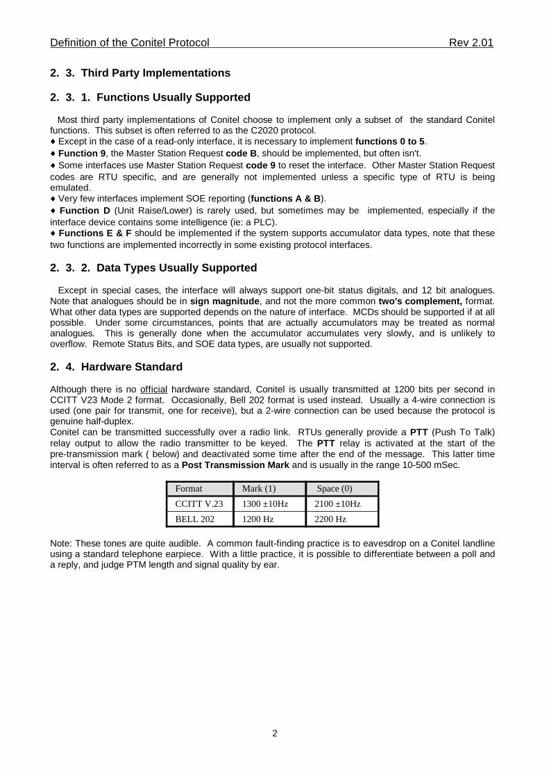
3. Message Block Format
A Conitel message consists of between 1 and 16 message blocks. Each message block is composed of32 bits, which are assigned as explained later. The first block in each message is preceded by apre-transmission mark (PTM ) and a start bit. The PTM is a mark "1" and the start bit is a space "0". The length of the PTM is set according to the communications hardware used, usually it is about 20 mSecfor a leased line and 300 mSec to 2 Sec for radio.
The receiving clock is synchronised by this first start bit, there are no further synchronising bits betweenfollowing blocks of the message. This is different from standard asynchronous serial data (eg: RS-232),which is synchronised at the beginning of each byte. As a conitel message may be a maximum of 512 bitslong, there is the need for extremely precise hardware timing elements.
Mark (1)
Silent
Space (0)
PTM Message Blocks
(1 to 16 blocks of 32 bits each)
StartBit
EOM Bit(Last Block Only)
Each message block contains the following parts:
Message Block
"A" "B" EOMBit
BCHCodeBitBit
A Section(12 bits)
B Section(12 bits)
Those A and B sections that contain data are called data blocks. By convention, these data blocks arereferred to by message block number and section number, eg: 1B, 2A, 2B, 3A, 3B, etc.
Bits within a data block are numbered from 1 to 12 starting from the left hand end (most other numberingschemes would go from 0 to 11 and start at the right hand end). Bit 1 is the MSB and is transmitted first.
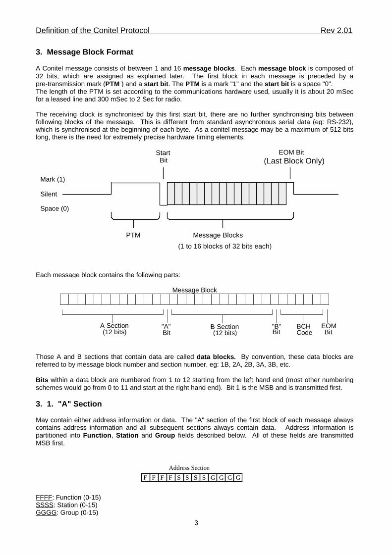
3. 1. "A" Section
May contain either address information or data. The "A" section of the first block of each message alwayscontains address information and all subsequent sections always contain data. Address information ispartitioned into Function, Station and Group fields described below. All of these fields are transmittedMSB first.
Address Section
F F F F S S S S G G G G
FFFF: Function (0-15)SSSS: Station (0-15)GGGG: Group (0-15)
Definition of the Conitel Protocol Rev 2.01
3
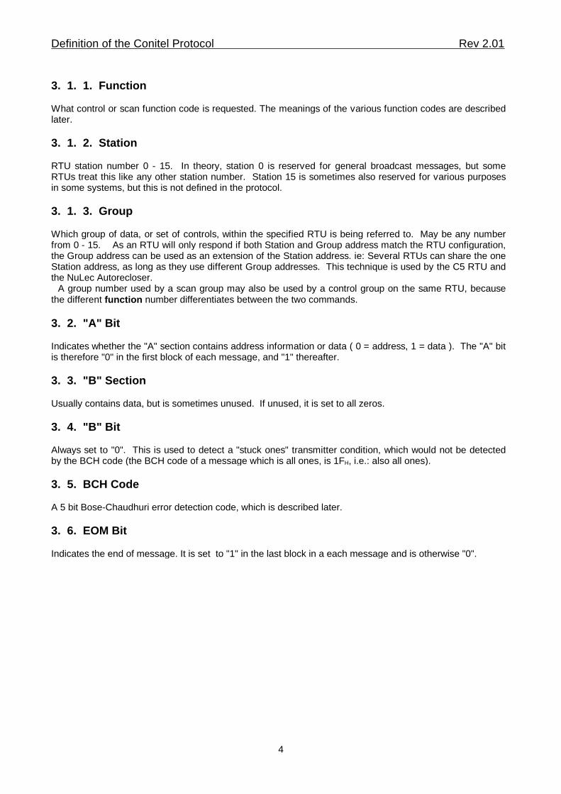
3. 1. 1. Function
What control or scan function code is requested. The meanings of the various function codes are describedlater.
3. 1. 2. Station
RTU station number 0 - 15. In theory, station 0 is reserved for general broadcast messages, but someRTUs treat this like any other station number. Station 15 is sometimes also reserved for various purposesin some systems, but this is not defined in the protocol.
3. 1. 3. Group
Which group of data, or set of controls, within the specified RTU is being referred to. May be any numberfrom 0 - 15. As an RTU will only respond if both Station and Group address match the RTU configuration,the Group address can be used as an extension of the Station address. ie: Several RTUs can share the oneStation address, as long as they use different Group addresses. This technique is used by the C5 RTU andthe NuLec Autorecloser. A group number used by a scan group may also be used by a control group on the same RTU, becausethe different function number differentiates between the two commands.
3. 2. "A" Bit
Indicates whether the "A" section contains address information or data ( 0 = address, 1 = data ). The "A" bitis therefore "0" in the first block of each message, and "1" thereafter.
3. 3. "B" Section
Usually contains data, but is sometimes unused. If unused, it is set to all zeros.
3. 4. "B" Bit
Always set to "0". This is used to detect a "stuck ones" transmitter condition, which would not be detectedby the BCH code (the BCH code of a message which is all ones, is 1FH, i.e.: also all ones).
3. 5. BCH Code
A 5 bit Bose-Chaudhuri error detection code, which is described later.
3. 6. EOM Bit
Indicates the end of message. It is set to "1" in the last block in a each message and is otherwise "0".
Definition of the Conitel Protocol Rev 2.01
4
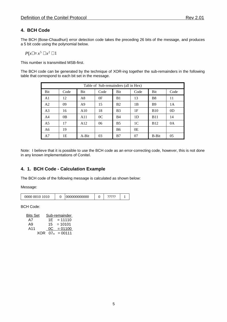
4. BCH Code
The BCH (Bose-Chaudhuri) error detection code takes the preceding 26 bits of the message, and producesa 5 bit code using the polynomial below.
P(x) = x5 + x2 + 1
This number is transmitted MSB-first.
The BCH code can be generated by the technique of XOR-ing together the sub-remainders in the followingtable that correspond to each bit set in the message.
05 B-Bit07 B703 A-Bit1E A7
0E B619 A6
0A B121C B506 A1217 A5
14 B111D B40C A110BA4
0D B101F B318 A1016 A3
1A B91B B215 A909 A2
11 B813 B10F A812 A1
CodeBitCodeBitCodeBitCodeBit
Table of Sub-remainders (all in Hex)
Note: I believe that it is possible to use the BCH code as an error-correcting code, however, this is not donein any known implementations of Conitel.
4. 1. BCH Code - Calculation Example
The BCH code of the following message is calculated as shown below:
Message:
1?????0000000000000 00000 0010 1010
BCH Code:
Bits Set Sub-remainder A7 1E = 11110 A9 15 = 10101 A11 0C = 01100 XOR 07H = 00111
Definition of the Conitel Protocol Rev 2.01
5
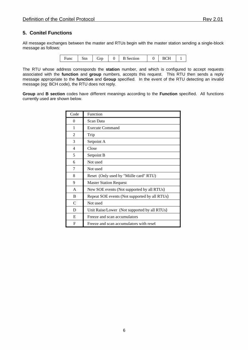
5. Conitel Functions
All message exchanges between the master and RTUs begin with the master station sending a single-blockmessage as follows:
1BCH0B Section0GrpStnFunc
The RTU whose address corresponds the station number, and which is configured to accept requestsassociated with the function and group numbers, accepts this request. This RTU then sends a replymessage appropriate to the function and Group specified. In the event of the RTU detecting an invalidmessage (eg: BCH code), the RTU does not reply.
Group and B section codes have different meanings according to the Function specified. All functionscurrently used are shown below.
Freeze and scan accumulators with resetF
Freeze and scan accumulators E
Unit Raise/Lower (Not supported by all RTUs)D
Not used C
Repeat SOE events (Not supported by all RTUs)B
New SOE events (Not supported by all RTUs)A
Master Station Request 9
Reset (Only used by "Miille card" RTU)8
Not used7
Not used6
Setpoint B5
Close4
Setpoint A3
Trip2
Execute Command1
Scan Data0
FunctionCode
Definition of the Conitel Protocol Rev 2.01
6
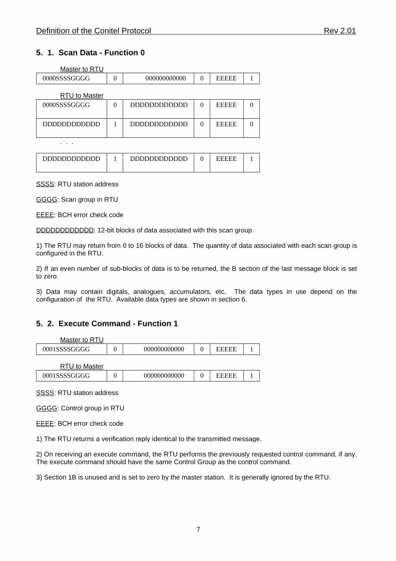
5. 1. Scan Data - Function 0
Master to RTU 1EEEEE0 000000000000 00000SSSSGGGG
RTU to Master0EEEEE0DDDDDDDDDDDD00000SSSSGGGG
0EEEEE0DDDDDDDDDDDD1DDDDDDDDDDDD
. . .
1EEEEE0DDDDDDDDDDDD1DDDDDDDDDDDD
SSSS: RTU station address
GGGG: Scan group in RTU
EEEE: BCH error check code
DDDDDDDDDDDD: 12-bit blocks of data associated with this scan group.
1) The RTU may return from 0 to 16 blocks of data. The quantity of data associated with each scan group isconfigured in the RTU.
2) If an even number of sub-blocks of data is to be returned, the B section of the last message block is setto zero.
3) Data may contain digitals, analogues, accumulators, etc. The data types in use depend on theconfiguration of the RTU. Available data types are shown in section 6.
5. 2. Execute Command - Function 1
Master to RTU1EEEEE0 000000000000 00001SSSSGGGG
RTU to Master1EEEEE0 000000000000 00001SSSSGGGG
SSSS: RTU station address
GGGG: Control group in RTU
EEEE: BCH error check code
1) The RTU returns a verification reply identical to the transmitted message.
2) On receiving an execute command, the RTU performs the previously requested control command, if any.The execute command should have the same Control Group as the control command.
3) Section 1B is unused and is set to zero by the master station. It is generally ignored by the RTU.
Definition of the Conitel Protocol Rev 2.01
7
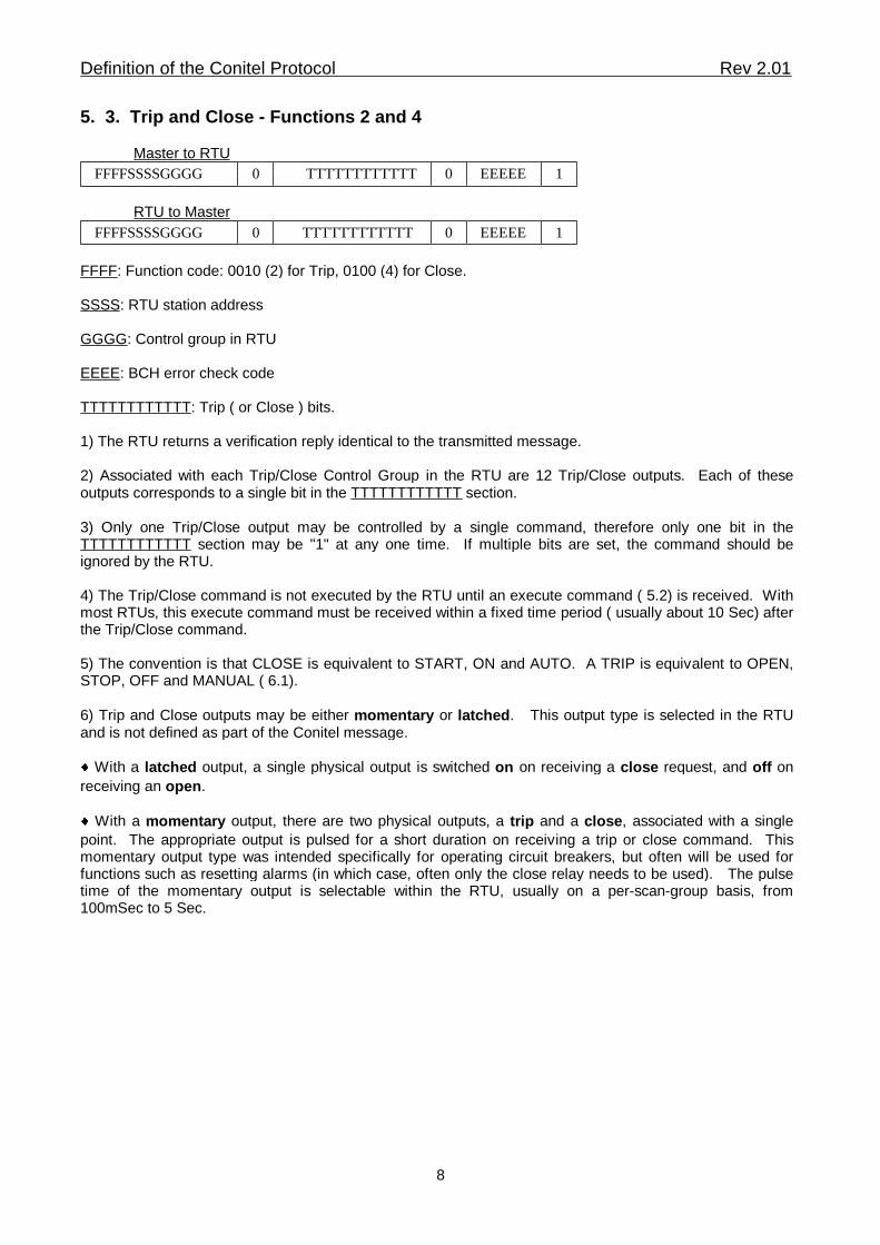
5. 3. Trip and Close - Functions 2 and 4
Master to RTU1EEEEE0TTTTTTTTTTTT0FFFFSSSSGGGG
RTU to Master1EEEEE0TTTTTTTTTTTT 0FFFFSSSSGGGG
FFFF: Function code: 0010 (2) for Trip, 0100 (4) for Close.
SSSS: RTU station address
GGGG: Control group in RTU
EEEE: BCH error check code
TTTTTTTTTTTT: Trip ( or Close ) bits.
1) The RTU returns a verification reply identical to the transmitted message.
2) Associated with each Trip/Close Control Group in the RTU are 12 Trip/Close outputs. Each of theseoutputs corresponds to a single bit in the TTTTTTTTTTTT section.
3) Only one Trip/Close output may be controlled by a single command, therefore only one bit in theTTTTTTTTTTTT section may be "1" at any one time. If multiple bits are set, the command should beignored by the RTU.
4) The Trip/Close command is not executed by the RTU until an execute command ( 5.2) is received. Withmost RTUs, this execute command must be received within a fixed time period ( usually about 10 Sec) afterthe Trip/Close command.
5) The convention is that CLOSE is equivalent to START, ON and AUTO. A TRIP is equivalent to OPEN,STOP, OFF and MANUAL ( 6.1).
6) Trip and Close outputs may be either momentary or latched. This output type is selected in the RTUand is not defined as part of the Conitel message.
� With a latched output, a single physical output is switched on on receiving a close request, and off on
receiving an open.
� With a momentary output, there are two physical outputs, a trip and a close, associated with a single
point. The appropriate output is pulsed for a short duration on receiving a trip or close command. Thismomentary output type was intended specifically for operating circuit breakers, but often will be used forfunctions such as resetting alarms (in which case, often only the close relay needs to be used). The pulsetime of the momentary output is selectable within the RTU, usually on a per-scan-group basis, from100mSec to 5 Sec.
Definition of the Conitel Protocol Rev 2.01
8
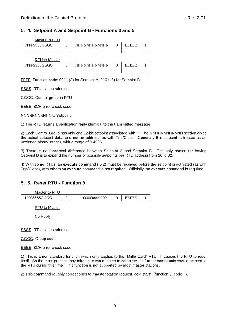
5. 4. Setpoint A and Setpoint B - Functions 3 and 5
Master to RTU1EEEEE0NNNNNNNNNNNN0FFFFSSSSGGGG
RTU to Master1EEEEE0NNNNNNNNNNNN0FFFFSSSSGGGG
FFFF: Function code: 0011 (3) for Setpoint A, 0101 (5) for Setpoint B.
SSSS: RTU station address
GGGG: Control group in RTU
EEEE: BCH error check code
NNNNNNNNNNNN: Setpoint
1) The RTU returns a verification reply identical to the transmitted message.
2) Each Control Group has only one 12-bit setpoint associated with it. The NNNNNNNNNNNN section givesthe actual setpoint data, and not an address, as with Trip/Close. Generally this setpoint is treated as anunsigned binary integer, with a range of 0-4095.
3) There is no functional difference between Setpoint A and Setpoint B. The only reason for havingSetpoint B is to expand the number of possible setpoints per RTU address from 16 to 32.
4) With some RTUs, an execute command ( 5.2) must be received before the setpoint is activated (as withTrip/Close), with others an execute command is not required. Officially, an execute command is required.
5. 5. Reset RTU - Function 8
Master to RTU1EEEEE0 000000000000 01000SSSSGGGG
RTU to Master
No Reply
SSSS: RTU station address
GGGG: Group code
EEEE: BCH error check code
1) This is a non-standard function which only applies to the "Miille Card" RTU. It causes the RTU to resetitself. As the reset process may take up to two minutes to complete, no further commands should be sent tothe RTU during this time. This function is not supported by most master stations.
2) This command roughly corresponds to "master station request, cold start", (function 9, code F).
Definition of the Conitel Protocol Rev 2.01
9
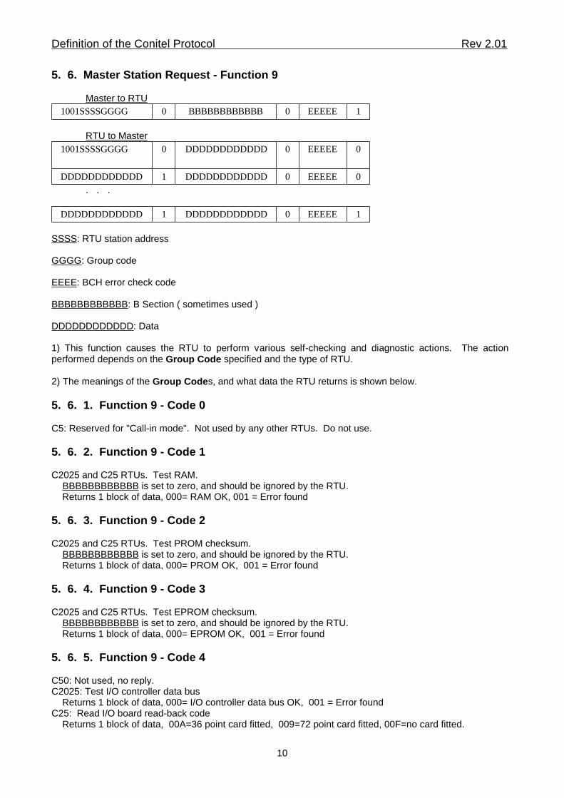
5. 6. Master Station Request - Function 9
Master to RTU1EEEEE0BBBBBBBBBBBB 01001SSSSGGGG
RTU to Master0EEEEE0DDDDDDDDDDDD01001SSSSGGGG
0EEEEE0DDDDDDDDDDDD1DDDDDDDDDDDD
. . .
1EEEEE0DDDDDDDDDDDD1DDDDDDDDDDDD
SSSS: RTU station address
GGGG: Group code
EEEE: BCH error check code
BBBBBBBBBBBB: B Section ( sometimes used )
DDDDDDDDDDDD: Data
1) This function causes the RTU to perform various self-checking and diagnostic actions. The actionperformed depends on the Group Code specified and the type of RTU.
2) The meanings of the Group Codes, and what data the RTU returns is shown below.
5. 6. 1. Function 9 - Code 0
C5: Reserved for "Call-in mode". Not used by any other RTUs. Do not use.
5. 6. 2. Function 9 - Code 1
C2025 and C25 RTUs. Test RAM. BBBBBBBBBBBB is set to zero, and should be ignored by the RTU. Returns 1 block of data, 000= RAM OK, 001 = Error found
5. 6. 3. Function 9 - Code 2
C2025 and C25 RTUs. Test PROM checksum. BBBBBBBBBBBB is set to zero, and should be ignored by the RTU. Returns 1 block of data, 000= PROM OK, 001 = Error found
5. 6. 4. Function 9 - Code 3
C2025 and C25 RTUs. Test EPROM checksum. BBBBBBBBBBBB is set to zero, and should be ignored by the RTU. Returns 1 block of data, 000= EPROM OK, 001 = Error found
5. 6. 5. Function 9 - Code 4
C50: Not used, no reply.C2025: Test I/O controller data bus Returns 1 block of data, 000= I/O controller data bus OK, 001 = Error foundC25: Read I/O board read-back code Returns 1 block of data, 00A=36 point card fitted, 009=72 point card fitted, 00F=no card fitted.
Definition of the Conitel Protocol Rev 2.01
10
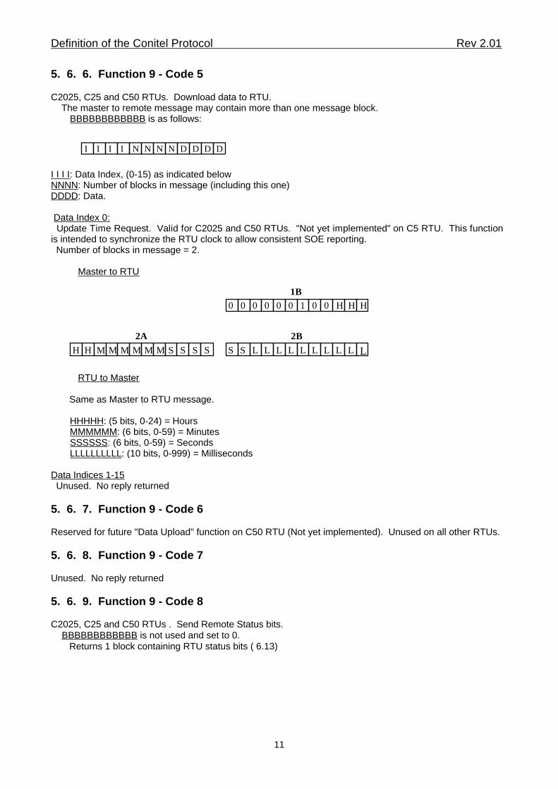
5. 6. 6. Function 9 - Code 5
C2025, C25 and C50 RTUs. Download data to RTU. The master to remote message may contain more than one message block. BBBBBBBBBBBB is as follows:
I I I I NN N N D D D D
I I I I: Data Index, (0-15) as indicated belowNNNN: Number of blocks in message (including this one)DDDD: Data.
Data Index 0: Update Time Request. Valid for C2025 and C50 RTUs. "Not yet implemented" on C5 RTU. This functionis intended to synchronize the RTU clock to allow consistent SOE reporting. Number of blocks in message = 2.
Master to RTU
H H H0 0 0 0 0 0 1 0 0
H H MM M M M M S S S S S S L L L L L L L L L L2A 2B
1B
RTU to Master
Same as Master to RTU message.
HHHHH: (5 bits, 0-24) = Hours MMMMMM: (6 bits, 0-59) = Minutes SSSSSS: (6 bits, 0-59) = Seconds LLLLLLLLLL: (10 bits, 0-999) = Milliseconds
Data Indices 1-15 Unused. No reply returned
5. 6. 7. Function 9 - Code 6
Reserved for future "Data Upload" function on C50 RTU (Not yet implemented). Unused on all other RTUs.
5. 6. 8. Function 9 - Code 7
Unused. No reply returned
5. 6. 9. Function 9 - Code 8
C2025, C25 and C50 RTUs . Send Remote Status bits. BBBBBBBBBBBB is not used and set to 0. Returns 1 block containing RTU status bits ( 6.13)
Definition of the Conitel Protocol Rev 2.01
11
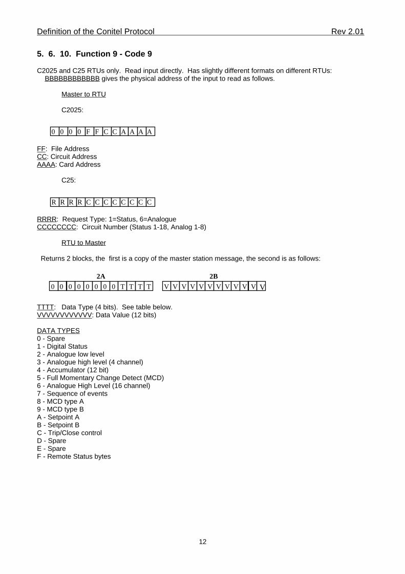
5. 6. 10. Function 9 - Code 9
C2025 and C25 RTUs only. Read input directly. Has slightly different formats on different RTUs: BBBBBBBBBBBB gives the physical address of the input to read as follows.
Master to RTU
C2025:
0 000 F CF C A A A A
FF: File AddressCC: Circuit AddressAAAA: Card Address
C25:
R RRR C CC C C C C C
RRRR: Request Type: 1=Status, 6=AnalogueCCCCCCCC: Circuit Number (Status 1-18, Analog 1-8)
RTU to Master
Returns 2 blocks, the first is a copy of the master station message, the second is as follows:
0 0 00 0 0 0 0 T T T T V V V V V V V V V V V V
2A 2B
TTTT: Data Type (4 bits). See table below.VVVVVVVVVVVV: Data Value (12 bits)
DATA TYPES0 - Spare1 - Digital Status2 - Analogue low level3 - Analogue high level (4 channel)4 - Accumulator (12 bit)5 - Full Momentary Change Detect (MCD)6 - Analogue High Level (16 channel)7 - Sequence of events8 - MCD type A9 - MCD type BA - Setpoint AB - Setpoint BC - Trip/Close controlD - SpareE - SpareF - Remote Status bytes
Definition of the Conitel Protocol Rev 2.01
12
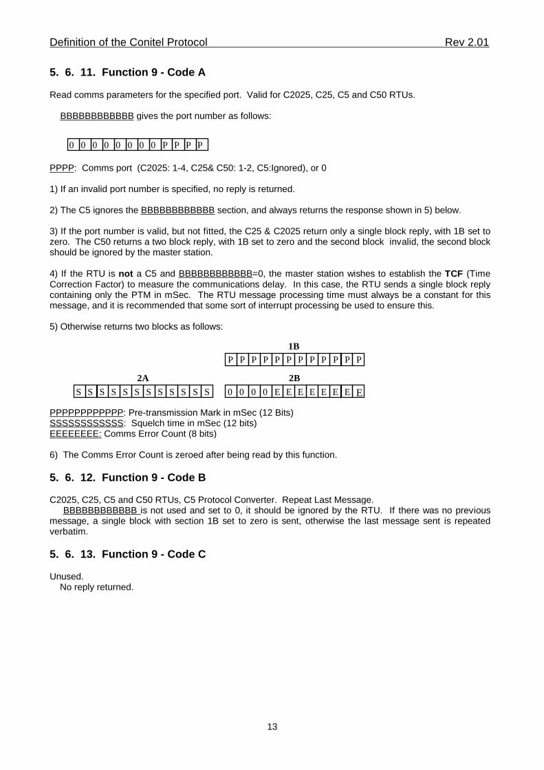
5. 6. 11. Function 9 - Code A
Read comms parameters for the specified port. Valid for C2025, C25, C5 and C50 RTUs.
BBBBBBBBBBBB gives the port number as follows:
0 000 0 00 0 P P P P
PPPP: Comms port (C2025: 1-4, C25& C50: 1-2, C5:Ignored), or 0
1) If an invalid port number is specified, no reply is returned.
2) The C5 ignores the BBBBBBBBBBBB section, and always returns the response shown in 5) below.
3) If the port number is valid, but not fitted, the C25 & C2025 return only a single block reply, with 1B set tozero. The C50 returns a two block reply, with 1B set to zero and the second block invalid, the second blockshould be ignored by the master station.
4) If the RTU is not a C5 and BBBBBBBBBBBB=0, the master station wishes to establish the TCF (TimeCorrection Factor) to measure the communications delay. In this case, the RTU sends a single block replycontaining only the PTM in mSec. The RTU message processing time must always be a constant for thismessage, and it is recommended that some sort of interrupt processing be used to ensure this.
5) Otherwise returns two blocks as follows:
P P PP P P P P P P P P
S S SS S S S S S S S S 0 0 0 0 E E E E E E E E
2A 2B
1B
PPPPPPPPPPPP: Pre-transmission Mark in mSec (12 Bits)SSSSSSSSSSSS: Squelch time in mSec (12 bits)EEEEEEEE: Comms Error Count (8 bits)
6) The Comms Error Count is zeroed after being read by this function.
5. 6. 12. Function 9 - Code B
C2025, C25, C5 and C50 RTUs, C5 Protocol Converter. Repeat Last Message. BBBBBBBBBBBB is not used and set to 0, it should be ignored by the RTU. If there was no previousmessage, a single block with section 1B set to zero is sent, otherwise the last message sent is repeatedverbatim.
5. 6. 13. Function 9 - Code C Unused. No reply returned.
Definition of the Conitel Protocol Rev 2.01
13
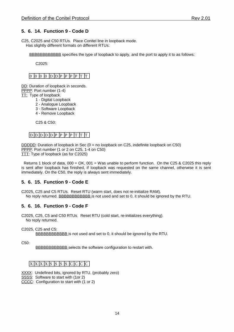
5. 6. 14. Function 9 - Code D
C25, C2025 and C50 RTUs. Place Conitel line in loopback mode. Has slightly different formats on different RTUs:
BBBBBBBBBBBB specifies the type of loopback to apply, and the port to apply it to as follows:
C2025:
0 000 D PD P P P T T
DD: Duration of loopback in seconds.PPPP: Port number (1-4)TT: Type of loopback.
1 - Digital Loopback2 - Analogue Loopback3 - Software Loopback4 - Remove Loopback
C25 & C50:
D DDD D PP P P T T T
DDDDD: Duration of loopback in Sec (0 = no loopback on C25, indefinite loopback on C50)PPPP: Port number (1 or 2 on C25, 1-4 on C50)TTT: Type of loopback (as for C2025)
Returns 1 block of data, 000 = OK, 001 = Was unable to perform function. On the C25 & C2025 this replyis sent after loopback has finished, if loopback was requested on the same channel, otherwise it is sentimmediately. On the C50, the reply is always sent immediately.
5. 6. 15. Function 9 - Code E
C2025, C25 and C5 RTUs. Reset RTU (warm start, does not re-initialize RAM). No reply returned. BBBBBBBBBBBB is not used and set to 0, it should be ignored by the RTU.
5. 6. 16. Function 9 - Code F
C2025, C25, C5 and C50 RTUs. Reset RTU (cold start, re-initializes everything). No reply returned.
C2025, C25 and C5:BBBBBBBBBBBB is not used and set to 0, it should be ignored by the RTU.
C50:BBBBBBBBBBBB selects the software configuration to restart with.
X XXX S SS S C C C C
XXXX: Undefined bits, ignored by RTU. (probably zero)SSSS: Software to start with (1or 2)CCCC: Configuration to start with (1 or 2)
Definition of the Conitel Protocol Rev 2.01
14
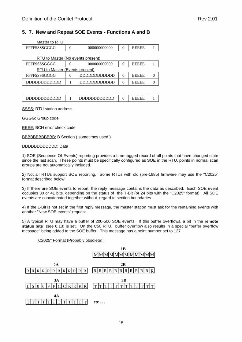
5. 7. New and Repeat SOE Events - Functions A and B
Master to RTU1EEEEE0 000000000000 0FFFFSSSSGGGG
RTU to Master (No events present) 1EEEEE0 000000000000 0FFFFSSSSGGGG
RTU to Master (Events present)0EEEEE0DDDDDDDDDDDD0FFFFSSSSGGGG
0EEEEE0DDDDDDDDDDDD1DDDDDDDDDDDD
. . .
1EEEEE0DDDDDDDDDDDD1DDDDDDDDDDDD
SSSS: RTU station address
GGGG: Group code
EEEE: BCH error check code
BBBBBBBBBBBB: B Section ( sometimes used )
DDDDDDDDDDDD: Data
1) SOE (Sequence Of Events) reporting provides a time-tagged record of all points that have changed statesince the last scan. These points must be specifically configured as SOE in the RTU, points in normal scangroups are not automatically included.
2) Not all RTUs support SOE reporting. Some RTUs with old (pre-1985) firmware may use the "C2025"format described below.
3) If there are SOE events to report, the reply message contains the data as described. Each SOE eventoccupies 30 or 41 bits, depending on the status of the T-Bit (or 24 bits with the "C2025" format). All SOEevents are concatenated together without regard to section boundaries.
4) If the L-Bit is not set in the first reply message, the master station must ask for the remaining events withanother "New SOE events" request.
5) A typical RTU may have a buffer of 200-500 SOE events. If this buffer overflows, a bit in the remotestatus bits (see 6.13) is set. On the C50 RTU, buffer overflow also results in a special "buffer overflowmessage" being added to the SOE buffer. This message has a point number set to 127.
"C2025" Format (Probably obsolete):
M M MM M M M M M M M M
R R RR R R R R R R R R R R R R R R R R R R R R2A 2B
1B
L S 00 F F C C K K K K T T T T T T T T T T T T
3A 3B
T T T T T T T T T T T T4A
etc . . .
Definition of the Conitel Protocol Rev 2.01
15
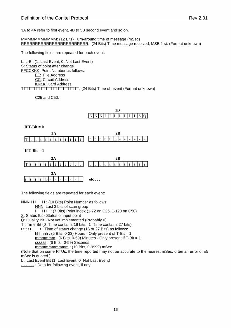
3A to 4A refer to first event, 4B to 5B second event and so on.
MMMMMMMMMMM: (12 Bits) Turn-around time of message (mSec)RRRRRRRRRRRRRRRRRRRRRRRR: (24 Bits) Time message received, MSB first. (Format unknown)
The following fields are repeated for each event:
L: L-Bit (1=Last Event, 0=Not Last Event)S: Status of point after changeFFCCKKK: Point Number as follows:
FF: File AddressCC: Circuit AddressKKKK: Card Address
TTTTTTTTTTTTTTTTTTTTTTTT: (24 Bits) Time of event (Format unknown)
C25 and C50:
I S QN N N I I I I I I
T t tt t t t t t t t t t t t t t L - - - - - -2A 2B
1B
T t tt t t t t t t t t t t t t t t t t t t t t
2A 2B
t t t t - - - - - - -
3Aetc . . .L
If T-Bit = 0
If T-Bit = 1
The following fields are repeated for each event:
NNN I I I I I I I : (10 Bits) Point Number as follows:NNN: Last 3 bits of scan groupI I I I I I I : (7 Bits) Point index (1-72 on C25, 1-120 on C50)
S: Status Bit - Status of input pointQ: Quality Bit - Not yet implemented (Probably 0)T : Time Bit (0=Time contains 16 bits, 1=Time contains 27 bits)t t t t t . . . t : Time of status change (16 or 27 Bits) as follows:
hhhhhh : (5 Bits, 0-23) Hours - Only present of T-Bit = 1mmmmmm : (6 Bits, 0-59) Minutes - Only present if T-Bit = 1ssssss : (6 Bits, 0-59) Secondsmmmmmmmmmm : (10 Bits, 0-9999) mSec
(Note that on some RTUs, the time reported may not be accurate to the nearest mSec, often an error of ±5mSec is quoted.)L : Last Event Bit (1=Last Event, 0=Not Last Event)- - - . . - : Data for following event, if any.
Definition of the Conitel Protocol Rev 2.01
16
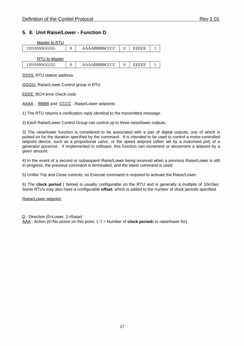
5. 8. Unit Raise/Lower - Function D
Master to RTU1EEEEE0AAAABBBBCCCC01101SSSSGGGG
RTU to Master1EEEEE0AAAABBBBCCCC01101SSSSGGGG
SSSS: RTU station address
GGGG: Raise/Lower Control group in RTU
EEEE: BCH error check code
AAAA , BBBB and CCCC : Raise/Lower setpoints
1) The RTU returns a verification reply identical to the transmitted message.
2) Each Raise/Lower Control Group can control up to three raise/lower outputs.
3) The raise/lower function is considered to be associated with a pair of digital outputs, one of which ispulsed on for the duration specified by the command. It is intended to be used to control a motor-controlledsetpoint device, such as a proportional valve, or the speed setpoint (often set by a motorised pot) of agenerator governor. If implemented in software, this function can increment or decrement a setpoint by agiven amount.
4) In the event of a second or subsequent Raise/Lower being received when a previous Raise/Lower is stillin progress, the previous command is terminated, and the latest command is used.
5) Unlike Trip and Close controls, no Execute command is required to activate the Raise/Lower.
6) The clock period ( below) is usually configurable on the RTU and is generally a multiple of 10mSec.Some RTUs may also have a configurable offset, which is added to the number of clock periods specified.
Raise/Lower setpoint:
D : Direction (0=Lower, 1=Raise)AAA : Action (0=No action on this point, 1-7 = Number of clock periods to raise/lower for)
Definition of the Conitel Protocol Rev 2.01
17
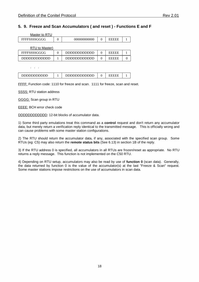
5. 9. Freeze and Scan Accumulators ( and reset ) - Functions E and F
Master to RTU1EEEEE0 0000000000000FFFFSSSSGGGG
RTU to Master) 1EEEEE0DDDDDDDDDDDD0FFFFSSSSGGGG
0EEEEE0DDDDDDDDDDDD1DDDDDDDDDDDD
. . .
1EEEEE0DDDDDDDDDDDD1DDDDDDDDDDD
FFFF: Function code: 1110 for freeze and scan. 1111 for freeze, scan and reset.
SSSS: RTU station address
GGGG: Scan group in RTU
EEEE: BCH error check code
DDDDDDDDDDDD: 12-bit blocks of accumulator data.
1) Some third party emulations treat this command as a control request and don't return any accumulatordata, but merely return a verification reply identical to the transmitted message. This is officially wrong andcan cause problems with some master station configurations.
2) The RTU should return the accumulator data, if any, associated with the specified scan group. SomeRTUs (eg: C5) may also return the remote status bits (See 6.13) in section 1B of the reply.
3) If the RTU address 0 is specified, all accumulators in all RTUs are frozen/reset as appropriate. No RTUreturns a reply message. This function is not implemented on the C50 RTU.
4) Depending on RTU setup, accumulators may also be read by use of function 0 (scan data). Generally,the data returned by function 0 is the value of the accumulator(s) at the last "Freeze & Scan" request.Some master stations impose restrictions on the use of accumulators in scan data.
Definition of the Conitel Protocol Rev 2.01
18
6. Data Types
Data returned by the "Scan Data" command may use the data types defined below. Note the following:
� The term "MCD" stands for "Momentary Change Detect".
� Generally the master station allows groups of bits within block to be defined as "unused".
� 12 bit types must occupy a whole block, and not overlap between blocks. 2, 4, 6 and 8 bit types need not
start on an even bit number, but must not overlap between blocks.� See note 6 in section 5.3 for output data types.
6. 1. One-bit Status1 Bit. An ordinary on/off digital point. The on and off states are referred to as "A" and "B", and aregenerally interpreted as follows:
"A" State = 1 = ON, RUNNING, IN SERVICE, AUTOMATIC, CLOSED, INHIBITED."B" State = 0 = OFF, STOPPED, OUT OF SERVICE, MANUAL, OPEN, ENABLED.
6. 2. Two-bit Status2 Bits. A four-state digital point occupying two bits. Intended to be used for circuit breakers and valveswith separate "open" and "closed" limit switches.
"0" State = 00 = In Transit"A" State = 10 = Closed"B" State = 01 = Open"AB" State = 11 = Invalid State
6. 3. One-bit MCD Type A2 Bits. Consists of a Change bit followed by a Status bit. The Change bit is set to 1 if the status bit beingmonitored has changed from open (0) to closed (1) one or more time since this data was last scanned. TheStatus bit is the same as the "One-bit Status" point in 5.1 above, except that it is inverted (Closed=0,Open=1). This data type is designed to cope with fleeting inputs.
6. 4. One-bit MCD Type B2 Bits. As for MCD type A, only the Change bit is set to 1 on a closed (1) to open (0) transition and theStatus bit is not inverted (Open=0, Closed=1).
6. 5. One-bit MCD Type C2 Bits. As for MCD type A, only the Change bit is set to 1 on more than one transition (1-0-1 or 0-1-0) of theassociated status and the Status bit is not inverted (Open=0, Closed=1).
6. 6. Two-bit MCD Type A4 Bits. Is to a one-bit MCD Type A what a two-bit status is to a one-bit status. Consists of two consecutiveone-bit MCD Type A points ie: C1S1C2S2.
6. 7. Two-bit MCD Type B4 Bits. As for MCD type A, only the Change bit is set to 1 on a closed (1) to open (0) transition.
6. 8. Two-bit MCD Type C4 Bits. As for MCD type A, only the Change bit is set to 1 on more than one transition (1-0-1 or 0-1-0) ofthe associated status.
6. 9. Twelve-bit Accumulator12 Bits. Treated as a 12 bit unsigned binary integer. Transmitted MSB first. Generally, these numbers arereturned in response to functions E & F and are not used in a normal scan request (function 0). In an RTUwhich does not return data in response to functions E & F, accumulators are part of the scan data. In thiscase, the number returned is not the current value of the accumulator, but the value at the last freezecommand. Some master stations impose certain restrictions on scan groups containing accumulators.
Definition of the Conitel Protocol Rev 2.01
19
6. 10. Twenty-Four-bit Accumulator24 Bits. The most significant 12 bit word is transmitted first. Generally the same as a 12-bit accumulator.Some master stations do not support this data type.
6. 11. Bipolar Analogue12 Bits. A standard sign-magnitude binary integer analogue. Transmitted Sign bit (0=Positive, 1=Negative) first, then MSB to LSB. Generally, this is raw data, with scaling to engineering units being doneby the master station.
6. 12. 1 to 5 Digit BCD4, 6, 8, 12, 16 or 20 Bits, corresponding to 1, 1.5, 2, 3, 4 and 5 digit BCD. Transmitted MSB first. Anon-signed BCD integer. BCD integers are traditionally derived from digital inputs monitoring devicesdriving LED displays, such as transformer tap-changers.
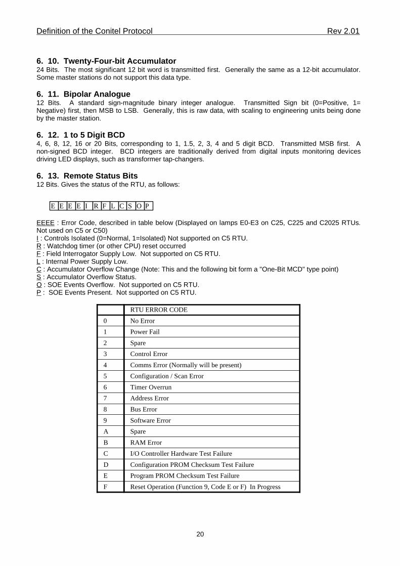
6. 13. Remote Status Bits12 Bits. Gives the status of the RTU, as follows:
E EEE I FR L C S O P
EEEE : Error Code, described in table below (Displayed on lamps E0-E3 on C25, C225 and C2025 RTUs.Not used on C5 or C50)I : Controls Isolated (0=Normal, 1=Isolated) Not supported on C5 RTU.R : Watchdog timer (or other CPU) reset occurredF : Field Interrogator Supply Low. Not supported on C5 RTU.L : Internal Power Supply Low.C : Accumulator Overflow Change (Note: This and the following bit form a "One-Bit MCD" type point)S : Accumulator Overflow Status.O : SOE Events Overflow. Not supported on C5 RTU.P : SOE Events Present. Not supported on C5 RTU.
Reset Operation (Function 9, Code E or F) In ProgressF
Program PROM Checksum Test FailureE
Configuration PROM Checksum Test FailureD
I/O Controller Hardware Test FailureC
RAM ErrorB
SpareA
Software Error9
Bus Error8
Address Error7
Timer Overrun6
Configuration / Scan Error5
Comms Error (Normally will be present)4
Control Error3
Spare2
Power Fail1
No Error0
RTU ERROR CODE
Definition of the Conitel Protocol Rev 2.01
20