Embed Size (px)
Citation preview
1 © 2002 Copyright Rockler Woodworking and Hardware
Part number 311373
1 Clamp Handle (2)2 Cam (4)3 Clamp Axle (2)4 Fence (1)5 Clamp Bar (2)6 Template Lock Knob (2)7 Clamp Springs (not shown)8 Fence Lock Knobs (2)
9 1/2" Plastic Template (1)10 Jig Body (1)11 "L" Shaped Adjustable Knobs (2)12 Cam lock Knob (4)13 Cam Lock Housing (4)14 Template Screws (4)15 Template Adjustment Bar (2)16 Adjustmment Bar Nuts (4)
(not shown)
PARTS LIST - 12" DOVETAIL JIG
IntroductionYour new dovetail jig will helpyou cut three varieties of half-blind
dovetails, plus box (also known as“finger”) joints. It willaccommodate drawer front stockfrom 1/2" to 1-1/4" thick, andboards up to 12" wide.
The following instructions beginby detailing how to set up the jig
and your router tomill flush half-blind dovetails(shown at left).Once you havemastered thistechnique, youcan add otherjoints to yourrepertoire such asoffset dovetails,rabbeted dovetailsand box joints.
(See page 4 for details.)
NOTE: Your jig comes with a 1/2" phenolic resin template. Additional7/16", 1/2" and 9/16" templates are also available and sold separately.
11
10
®
A N D H A R D W A R EW O O D W O R K I N G
1
2 34
5 6
9
11
14
8
13
15
12
12" Dovetail Jig Instructions
2
Tool Safety Rules1. Keep your work area clean and
well lighted.2. Do not use a router with this jig
when tired or under the influence of drugs, alcohol or medication.
3. Avoid loose clothing or jewelry.4. Unplug the router to make any
adjustments.5. Remove the wrench(es) before
starting the router.6. Always wear eye, dust, and
hearing protection.7. NEVER lift the router off the jig
while the bit is still spinning.8. Secure the jig to a solid base
(such as a heavy workbench) before using.
9. Keep children and other distractions away.
10. Always replace damaged parts before using the jig.
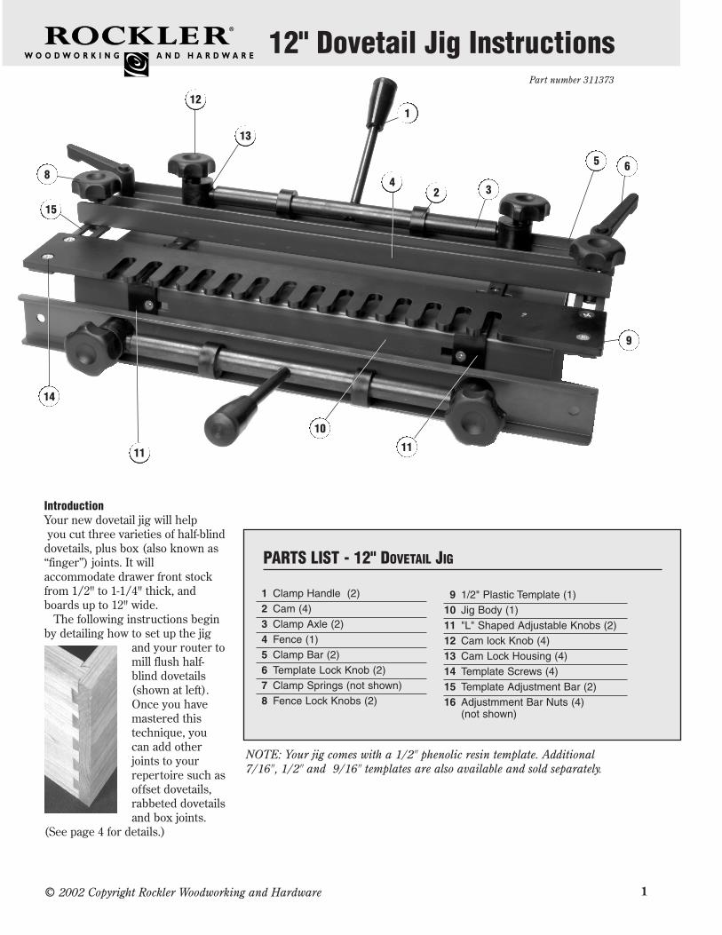
Secure the JigTwo bolt holes in the bottom of thejig allow permanent attachment toa workbench or similar stable base.Where workspace is limited, thesame holes allow mounting to ashop-built mobile base (see Figure1) that can be secured in the jawsof a vise. The jig can then bestored elsewhere, when not in use.The base is just two pieces of sheetstock (plywood, MDF, Melamine™
etc.), screwed together at 90°. Anoptional glued dado strengthensthe joint and provides extrastability.
Set Up the RouterIncluded with your jig are a 14°1/2" dovetail bit (with a 1/4"shank) and a 7/16" guide bushing,both of which are shown in fig.2.The bushing is universal: it fitsmost popular brands of routers andafter-market bases. (In the remotechance that youhave difficultyattaining a perfectfit, consult yourrouter’smanufacturer:they usually offera guide bushingas an option.)
Install thebushing in the
router base and secure it with theincluded threaded ring. Tighten thering securely, then slide the basetoward the motor housing andinstall the bit. Set the bit height at9/16" (from the router base, notthe bushing).
Locate the StopsThe jig is equipped with two stopsthat locate the drawer parts andallow repetitive milling: once theyare set, you can build as manydrawers as you need.
The first step is to to ensure thatthe dovetails are evenly spaced onyour workpiece (that is, there is thesame amount of pin or tail top andbottom). With the correct templateinstalled – to begin with, use the1/2" one – slide a piece of scrap thesame width as your drawer stockinto the jig. Center the board (leftand right) on the template fingers,as shown in figure 3. The idea is tohave the same amount of finger orgap showing at each side of theboard. Make sure the board lies at90° to the front of the jig, thenloosen the four screws in theadjustable stop (the left one, Part11, see figure 4), and slide it snugagainst the board. Tighten the fourscrews.
Insert the Drawer PartsDuring initial set-up adjustmentalways use test pieces the samethickness and width as your drawersides that you will be milling. Onlyinstall the actual drawer sides afteryou've produced a satisfactory jointin the test pieces. Figures 5, 6and 7 illustrate the process
A shop-built baseallows for quicksetup in theworkbench vise, andeasy storage.
© 2002 Copyright Rockler Woodworking and Hardware
Equal distance
Figure 1
Figure 2
Figure 4
Figure 3
11
3
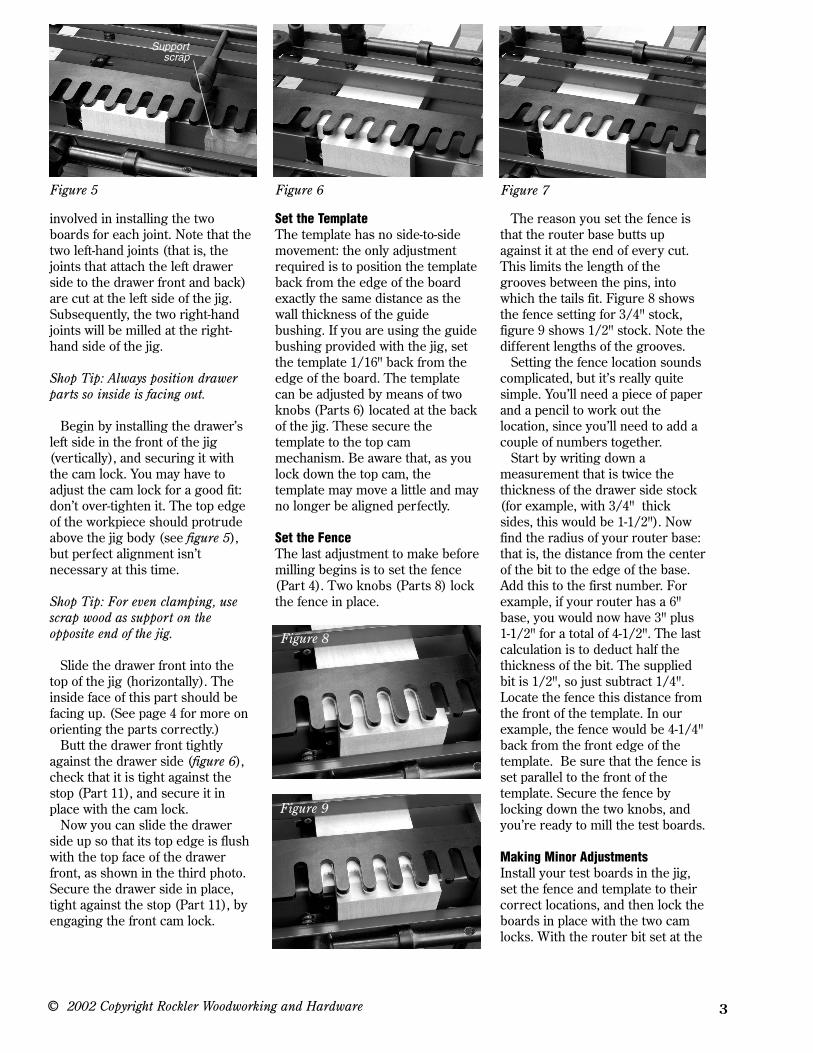
involved in installing the twoboards for each joint. Note that thetwo left-hand joints (that is, thejoints that attach the left drawerside to the drawer front and back)are cut at the left side of the jig.Subsequently, the two right-handjoints will be milled at the right-hand side of the jig.
Shop Tip: Always position drawerparts so inside is facing out.
Begin by installing the drawer’sleft side in the front of the jig(vertically), and securing it withthe cam lock. You may have toadjust the cam lock for a good fit:don’t over-tighten it. The top edgeof the workpiece should protrudeabove the jig body (see figure 5),but perfect alignment isn’tnecessary at this time.
Shop Tip: For even clamping, usescrap wood as support on theopposite end of the jig.
Slide the drawer front into thetop of the jig (horizontally). Theinside face of this part should befacing up. (See page 4 for more onorienting the parts correctly.)
Butt the drawer front tightlyagainst the drawer side (figure 6),check that it is tight against thestop (Part 11), and secure it inplace with the cam lock.
Now you can slide the drawerside up so that its top edge is flushwith the top face of the drawerfront, as shown in the third photo.Secure the drawer side in place,tight against the stop (Part 11), byengaging the front cam lock.
Set the TemplateThe template has no side-to-sidemovement: the only adjustmentrequired is to position the templateback from the edge of the boardexactly the same distance as thewall thickness of the guidebushing. If you are using the guidebushing provided with the jig, setthe template 1/16" back from theedge of the board. The templatecan be adjusted by means of twoknobs (Parts 6) located at the backof the jig. These secure thetemplate to the top cammechanism. Be aware that, as youlock down the top cam, thetemplate may move a little and mayno longer be aligned perfectly.
Set the FenceThe last adjustment to make beforemilling begins is to set the fence(Part 4). Two knobs (Parts 8) lockthe fence in place.
The reason you set the fence isthat the router base butts upagainst it at the end of every cut.This limits the length of thegrooves between the pins, intowhich the tails fit. Figure 8 showsthe fence setting for 3/4" stock,figure 9 shows 1/2" stock. Note thedifferent lengths of the grooves.
Setting the fence location soundscomplicated, but it’s really quitesimple. You’ll need a piece of paperand a pencil to work out thelocation, since you’ll need to add acouple of numbers together.
Start by writing down ameasurement that is twice thethickness of the drawer side stock(for example, with 3/4" thicksides, this would be 1-1/2"). Nowfind the radius of your router base:that is, the distance from the centerof the bit to the edge of the base.Add this to the first number. Forexample, if your router has a 6"base, you would now have 3" plus1-1/2" for a total of 4-1/2". The lastcalculation is to deduct half thethickness of the bit. The suppliedbit is 1/2", so just subtract 1/4".Locate the fence this distance fromthe front of the template. In ourexample, the fence would be 4-1/4"back from the front edge of thetemplate. Be sure that the fence isset parallel to the front of thetemplate. Secure the fence bylocking down the two knobs, andyou’re ready to mill the test boards.
Making Minor AdjustmentsInstall your test boards in the jig,set the fence and template to theircorrect locations, and then lock theboards in place with the two camlocks. With the router bit set at the
© 2002 Copyright Rockler Woodworking and Hardware
Figure 5 Figure 6
Figure 8
Figure 9
Figure 7
Supportscrap

correct height, visually check thatthe bit won’t engage the templateor any part of the jig. Begin cuttingfrom left to right, making sure thatthe bushing rides the template allthe way to the back of each groove.DO NOT LIFT THE ROUTER OFFTHE TEMPLATE WHILE THEMOTOR IS RUNNING. If you do,the bit will destroy your template.
If the resulting joint is too sloppy,raise the bit slightly and try again.Conversely, if the fit is too tight,lower the bit. Make adjustments inapproximately 1/64" increments, asa small adjustment can make a lotof difference.
If the two partsfit together well, but the tails areproud, move the fence back theamount the tails are proud. If thetails slide too far into the grooves(also called “sockets”) between thepins, move the fence forward theamount they are shy.
If you don’t have an even amountof pin or tail at the top and bottomof the drawer, revisit the sectionentitled Locate the Stops, above.Sometimes you may want to have afull pin at the top and a half pin atthe bottom. This is easilyaccomplished by visually adjustingthe stops in the manner describedin that section.
Continue milling test pieces(both left and right) until youachieve results that aresatisfactory. Only then should youmill actual workpieces.
Drawer LayoutIt is recommended that you keeptrack of the parts of each drawerby numbering and labeling them,then milling them in the sameorder every time you build adrawer or box. This repetition willvirtually eliminate mistakes, withpractice.
Refer to the drawing above to see
4
how this is done. The parts of thedrawer are laid out in their properorientation, then each piece islabeled on the inside face (FRONT, BACK, LEFT SIDE,RIGHT SIDE). You can writedirectly on the part with a softpencil, or use masking tape.
Mark the faces next: each faceshould have a notation that sayswhich way is up.
Finally, mark the corners withdesignated number, 1 through 4.For example, the left side of thedrawer in the illustration meets thefront at corner #1, so each part isso labeled.
If you can develop a habit ofmarking the drawers in exactly thesame fashion every time, errorswill be few and far between.
13
31 2 2
4 4
FRONT
BACKLEFT
RIGHT
Your jig can help you mill three variations of thehalf-blind dovetail.
Offset Dovetails (top drawing) can be used whenthere is no separate drawer face to attach to thedrawer front. They give you an integrated overlay:that is, part of the drawer front overlays the faceframe of the chest or cabinet. To mill the joint, justadd 3/4" to the length of the front. The part thick-ness should be a minimum 7/8" thick, and the rab-bet on each end should be milled before insertingthe piece in the dovetail jig. Move the backstop3/8" back, and test your setup on scrap.
Rabbeted Dovetails (middle drawing) add a lip tothe top, bottom and sides of the drawer front. Theyare milled in the same fashion as the offset dovetail(above), except that you must reset the right andleft stops for the drawer front. Note: You’ll need toshim the horizontal/top arm of the “L-shaped” stop3/8" so that the offset is 1/8" instead of the standard 1/2", then proceed.
Box or Finger Joints (lower drawing) can bemilled by securing both parts in the jig vertically.One piece of stock must be lined up with the topstops, while the other is lined up with the frontstops: this means that the front board is 1/2" to theleft of the back one. Set the router bit depth (a 1/2"straight bit) to the exact thickness of the stock. Youcan use a stock bit or a 1/2" bearing-guided bit. Ifusing a bearing-guided bit, shim the template so itis high enough that the bit won’t cut it.
Some other joints you can make withyour Rockler 12" dovetail jig
© 2002 Copyright Rockler Woodworking and Hardware
Shop Tip:Heighten/tighten,
lower/loosen...
Lower to loosen
Router Base
1 4Left side up
Heighten to tighten