Embed Size (px)
Citation preview
WOOD FIRE OWNERS MANUAL WARNING: Improper installation, adjustment, alteration, service or maintenance can cause injury or property damage. For assistance or additional information consult an authorized technician, or your Wood Fire Dealer. FOR YOUR SAFETY: Do not store or use gasoline or other flammable vapors and liquids in the vicinity of this appliance. Installation and service must be performed by authorized personnel. INSTALLATION OF YOUR WOODFIRE: Please refer to the Installation Manual and Installation Specification Sheets specific for your model. PLEASE KEEP THESE INSTRUCTIONS FOR FURTHER REFERENCE. Manufactured in New Zealand by: Distributed in Australia by: GLEN DIMPLEX NEW ZEALAND LIMITED GLEN DIMPLEX AUSTRALIA PTY LIMITED P.O.Box 58473, Botany, Manukau - 2163 Unit 1, 21 Lionel Road, Mount Waverley, Victoria 3149 Ph: 0800 666 2824 Ph: 1 300 556 816 Fax: 09 274 8472 Fax: 1 800 058 900 Email: [email protected] Email: [email protected] Web: www.glendimplex.co.nz Web: www.glendimplex.com.au 15th Jun 2014 Part No.593286
1
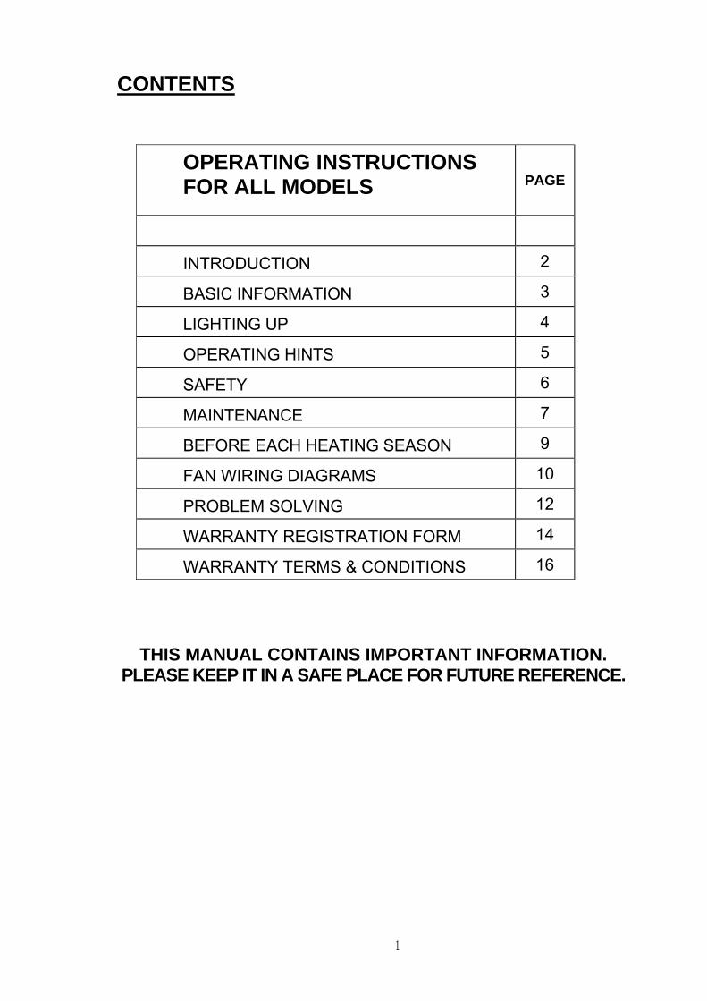
CONTENTS
OPERATING INSTRUCTIONS FOR ALL MODELS
PAGE
INTRODUCTION 2
BASIC INFORMATION 3
LIGHTING UP 4
OPERATING HINTS 5
SAFETY 6
MAINTENANCE 7
BEFORE EACH HEATING SEASON 9
FAN WIRING DIAGRAMS 10
PROBLEM SOLVING 12
WARRANTY REGISTRATION FORM 14
WARRANTY TERMS & CONDITIONS 16
THIS MANUAL CONTAINS IMPORTANT INFORMATION. PLEASE KEEP IT IN A SAFE PLACE FOR FUTURE REFERENCE.
2
INTRODUCTION In the interests of your safety, all building regulatory Authorities in Australia and New Zealand require any wood fire installation to comply with Installation Standard AS/NZS 2918. They may also have local requirements in addition to those in the Standard. Check with your local Building Authority before commencing installation, to find if you will require a Permit and whether there are extra requirements. All our Wood fires have been tested to ensure that they will meet the appropriate safety Standard requirements if the instructions in this book and additional instructions supplied with the fire are followed. As the safety and emissions performance can be affected by altering the appliance, no modifications are allowed without written permission from the manufacturer. Wood fire models covered by this manual have been tested to demonstrate compliance with current general emission requirements in Australia and New Zealand, but some areas have stricter limits. Only some of the models meet those limits, so check before installing a particular model. In areas covered by stricter emission regulations:- (I) If a water-heating device is permitted, it must be factory fitted or be a genuine accessory retrofitted strictly in accordance with the instructions supplied by Glen Dimplex New Zealand Ltd or Glen Dimplex Australia Pty Ltd. (II) Coal must not be used as a fuel unless it is a multi fuel fire. (III) Wood fuel must have a moisture content of less than 25%.
WE RECOMMEND THAT THE INSTALLATION OF YOUR WOODFIRE BE CARRIED OUT BY A QUALIFIED SPECIALIST INSTALLER.
WARNING: IF ANY ELECTRICAL WORK IS REQUIRED, IT MUST BE CARRIED OUT BY A LICENSED ELECTRICIAN.
WARNING: IN SOME REGIONS POWER POINTS ARE NOT PERMISSIBLE WITHIN THE FLOOR PROTECTOR AREA; PLEASE CHECK WITH YOUR LOCAL AUTHORITY.
WARNING: FOR APPLIANCES WITH WATER HEATING DEVICES: DO NOT CONNECT TO AN UNVENTED HOT WATER SYSTEM. INSTALL IN ACCORDANCE WITH AS 3500.4.1 OR NZS 4603 AND THE APPROPRIATE REQUIREMENTS OF THE RELEVANT BUILDING CODE/S.
WARNING: IN NEW ZEALAND, FAN & WATER HEATING DEVICE CAN BE INSTALLED ONLY FOR RURAL APPLICATION EXCEPT, INSERT MODEL MASPORT LE4000 PROVINCIAL, WHICH IS TESTED WITH FAN & FAN MUST BE INSTALLED BY A REGISTERED ELECTRICIAN. INSERT MODEL I3000 WET, WHICH IS TESTED WITH WATER HEATING DEVICE. BOTH THESE MODELS ARE AUTHORIZED BY ECAN.
WARNING: TO AVOID THE RISK OF ELECTRIC SHOCK OR CONTACT WITH MOVING PARTS, ONLY THE MANUFACTURER AUTHORIZED SERVICE AGENTS OR SIMILARLY QUALIFIED PERSONS SHOULD REMOVE THE BOTTOM PANELS WHICH ALLOW ACCESS TO FANS.
WARNING: THE APPLIANCE AND FLUE SYSTEM MUST BE INSTALLED IN ACCORDANCE WITH AS/NZS 2918:2001 AND THE APPROPRIATE REQUIREMENTS OF THE LOCAL AUTHORITY BUILDING CODE OR CODES.
WARNING: APPLIANCES INSTALLED IN ACCORDANCE WITH THIS STANDARD SHALL COMPLY WITH THE REQUIREMENTS OF AS/NZS 4013 WHERE REQUIRED BY THE REGULATORY AUTHORITY, I.E. THE APPLIANCE SHALL BE IDENTIFIABLE BY A COMPLIANCE PLATE WITH THE MARKING ‘TESTED TO AS/NZS 4013’. ANY MODIFICATION OF THE APPLIANCE THAT HAS NOT BEEN APPROVED IN WRITNG BY THE TESTING AUTHORITY IS CONSIDERED TO BE IN BREACH OF THE APPROVAL GRANTED FOR COMPLIANCE WITH AS/NZS 4013.
CAUTION: Please ensure that only components approved by Glen Dimplex are used for the installation, as substitutes may adversely affect performance and might nullify compliance with the requirements of AS/NZS 2918.
CAUTION: Mixing of appliance or flue system components from different sources or modifying the dimensional specification of components may result in hazardous conditions. Where such action is considered, the manufacturer should be consulted in the first instance.
CAUTION: Cracked/broken components e.g. door glass, makes the installation unsafe.
3
OPERATING INSTRUCTIONS — ALL MODELS BASIC INFORMATION
DOOR HANDLE Front mounted handles.
To open the door:- Rotate the handle upward anti-clockwise to the 1 o’clock position. To close the door:- Push the door toward the fire box, using the handle, and turn the handle clockwise to the 4 or 5 o’clock position.
Side mounted handles. To open the door:- Pull the lower part of the handle, forward and upward. To close the door: - Hold the handle up whilst closing the door. Push the handle down to the vertical position to lock the door.
HEAT OUTPUT CONTROL (AIR SLIDE) This control has a sliding action. It is clearly marked with a wedge shaped symbol or letters ‘H’ and ‘L’. Slide the control in the direction of the wide end of the wedge to increase the heat output and toward the narrow end to decrease it. Shutting a high fire down rapidly by starving it of air will result in heavy particulates of unburned fuel which are undesirable emissions. For this reason, turn down heat output control from Hi to Low position gradually. Note: - The lever on some models is marked ‘H’ for high fire and ‘L’ for low fire.
EXTENDED BURNING Our Fires will burn for a long period. To achieve this, level the embers and load the fire wood lying front to back. (Except Atlanta Bay (NZ) model which was emission tested with fuel loading from side to side) Use large logs and ensure that there are gaps between the fire wood to allow air to reach all the pieces of wood. Open the air inlet fully for 15 to 20 minutes. When the fire is burning fiercely, reduce the air intake in stages to the minimum opening. NEVER LET THE FIRE SMOULDER. Smoldering is not good for the environment. It will create creosote buildup in the fire, flue and will increase risk of flue fires or flue blockages.
FAN OPERATION Inbuilt Wood fires SHOULD NOT be operated on maximum heat with very dry softwood, unless the fan is operating. On freestanding woodfires, the optional fan MUST only be operated when the heat output control (air slide) on the fire, is set on ‘HIGH’. Not all models have a fan option.
ESSENTIAL ADVICE Correct installation, the use of only DRY- SEASONED wood and adherence to the following instructions will ensure satisfactory performance.
WARNING: MAKE SURE THE MINIMUM HEATER-TO-WALL DISTANCES SHOWN ON THE SPECIFICATION SHEET, ARE ALWAYS MAINTAINED BETWEEN THE HEATER AND ANY HEAT SENSITIVE ITEMS. (WALLS, FURNITURE, DRAPES, ETC.)
WARNING: DO NOT STORE FUEL WITHIN THE HEATER INSTALLATION CLEARANCES. WARNING: DO NOT USE FLAMMABLE LIQUIDS OR AEROSOLS OR PLACE THESE IN THE
VICINITY OF THIS APPLIANCE WHEN IT IS OPERATING. WARNING: THIS APPLIANCE MUST NOT BE USED AS AN OPEN FIRE. WARNING: WHEN FITTED WITH A WATER HEATING BOOSTER, THIS APPLIANCE MUST
NOT BE CONNECTED TO AN UNVENTED HOT WATER SYSTEM. THIS APPLIANCE MUST BE INSTALLED WITH AN OPEN VENT. THERE MUST BE NO SHUT-OFF OR NON-RETURN VALVES IN THE PIPING SYSTEM. REFER TO WATER PIPE INSTALLATION INSTRUCTIONS.
4
LIGHTING UP CAUTION: THIS APPLIANCE SHOULD BE MAINTAINED AND OPERATED AT ALL
TIMES IN ACCORDANCE WITH THESE INSTRUCTIONS 1. Slide the heat output control fully to the high setting. 2. Crumple up several double sheets of newspaper and place them in the centre of the
firebox. Build a pyramid of thin, dry kindling wood on the paper with some heavier pieces on top. Light the paper at the bottom and leave the door slightly open until the kindling has ‘caught’, then latch the door shut firmly.
3. Gradually build up the fire by adding 2 or 3 small logs at a time whilst ensuring the heat output control is still on the High setting.
4. When the kindling is well alight, open the door slowly and add some larger pieces of wood. When loading fuel, place the pieces of wood in a front-to-back direction to ensure good air access and the cleanest possible burning. Do not throw fuel pieces into the firebox as this may damage the top baffle and the insulating boards or firebricks.
5. Close and latch the door firmly. 6. Move the heat output control away from the maximum position only after the fire is
well established. A new wood fire should not be run at higher than half setting beyond the first 30 minutes until it has been used for a total of 8 hours. Once fully ‘run in’, we recommend running at full heat for up to one hour after lighting as this will minimize creosote build-up in the flue. The control can then be set wherever desired.
7. When reloading your fire make sure the air control is fully opened to high setting prior to opening the door. This will reduce possibility of smoke spillage into the room. Open the door slowly and reload the fire. Leave the heat output or air slide control on high for a few minutes before adjusting the control to suit the heat level required.
8. After initial burns and after regular cleaning of the firebox, leave 10-15 mm layer of ash at the bottom of the firebox. In case of cast fireboxes roughly level up to top of the bottom ribs. Ash acts as an insulator between steel/cast bottom and the fire, which helps in quick light up and air circulation within firebox.
WARNING: THE SPECIAL HIGH TEMPERATURE PAINT ON THE FIREBOX WILL
EMIT SOME SMOKE AS IT CURES DURING THE FIRST TWO OR THREE SESSIONS OF RUNNING. VENTILATE THE HOUSE DURING THESE INTIAL BURNS. WHILE CURING THE SURFACE HEATED PAINT SOFTENS, SO DO NOT TOUCH HOT SURFACE DURING THIS PROCESS. ALSO THE HEATED COATING ON THE FIRBOX WILL GIVE OFF ODOROUS SMOKE CONTAINING CARBON DIOXIDE. WITHOUT ADEQUATE VENTILATION CONCERTRATION OF SMOKE COULD IRRITATE, OR BE UPSETTING. BABIES, SMALL CHILDREN, PREGNANT WOMEN, ELDERLY PERSONS, PERSONS SUBJECT TO PULMONARY HYPERSENSITIVITY AND PETS SHOULD NOT BE IN THE AREA DUE TO THESE CARBON DIOXIDE FUMES CAUSING AN IMBALANCE IN THE AIR QUALITY. OPEN DOORS AND WINDOWS AND USE A FAN IF NECESSARY. AFTER THESE INITIAL BURNS, THERE SHOULD BE NO SMOKE.
WARNING: DO NOT USE FLAMMABLE LIQUIDS OR AEROSOLS TO START OR
REKINDLE THE FIRE. WARNING: ALWAYS MOVE THE AIR CONTROL TO THE OPEN POSITION (TO THE
RIGHT) BEFORE OPENING THE FIRING DOOR.
CAUTION: THE APPLIANCE MUST NOT BE OPERATED WITH A CRACKED GLASS.
5
OPERATING HINTS FOR CLEAN BURNING AND BEST EFFICIENCY FUEL: USE ONLY WOOD THAT HAS BEEN AIR DRIED IN A SHELTERED WELL
VENTILATED STACK, PREFERABLY FOR AT LEAST 12 MONTHS. In all Clean Air Zones in New Zealand, only wood may be used as fuel, and it must have moisture content not greater than 25% (measured on a dry weight basis). • Do not burn driftwood, treated, and painted wood or coloured paper as these
can corrode the wood fire and flue.
CAUTION: THE USE OF SOME TYPES OF PRESERVATIVE TREATED WOOD AS FUEL CAN BE HAZARDOUS.
• Add fuel reasonably often. A large fuel load placed on a dying fire can drop
combustion temperatures undesirably. • Avoid large smouldering fires. A small intense fire is more efficient.
• Move the heat control to high setting for a minute or so and turn off the air
circulating fan (if fitted) before opening the door on a low burning fire. This will clear away any fumes in the firebox.
• Always open the door SLOWLY, and close and latch it shut securely again as soon
as possible after re-loading.
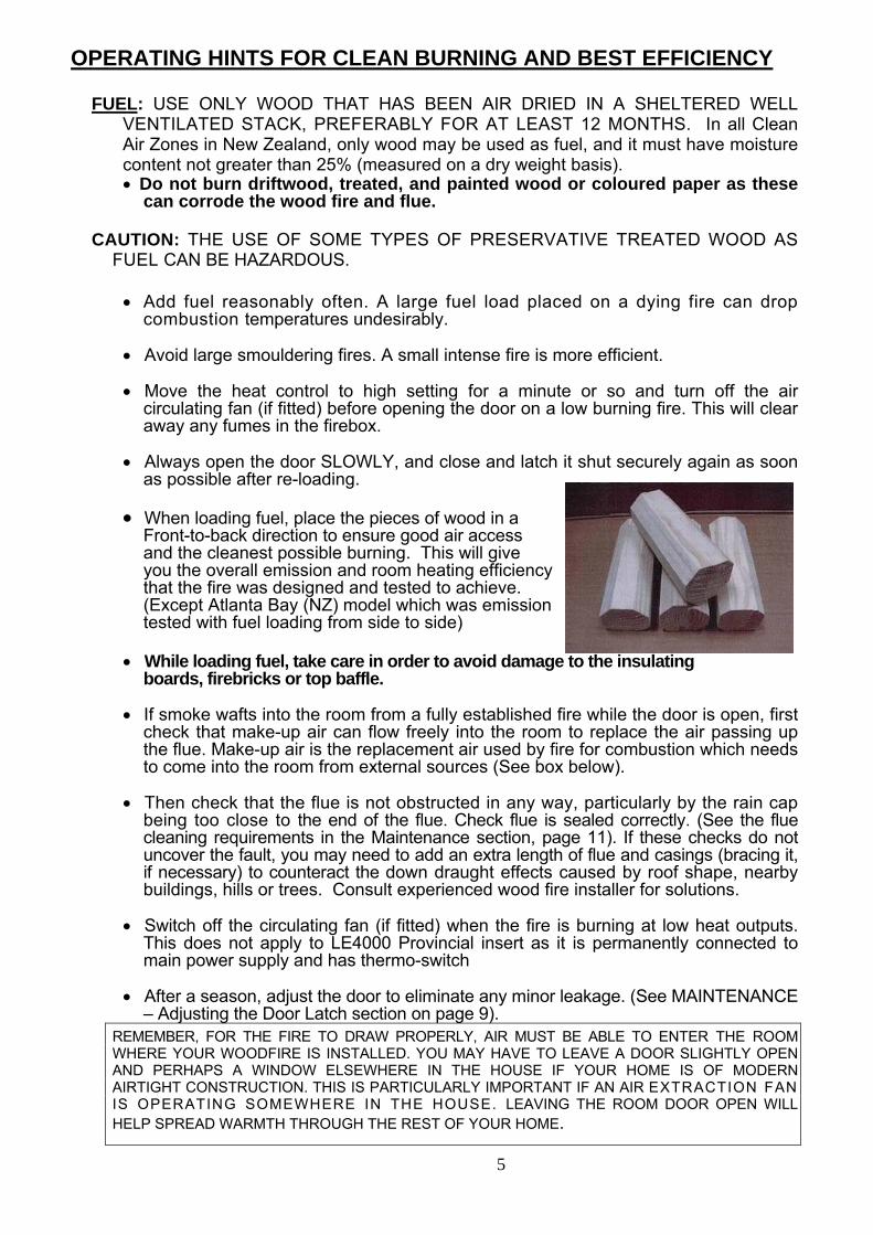
• When loading fuel, place the pieces of wood in a Front-to-back direction to ensure good air access and the cleanest possible burning. This will give you the overall emission and room heating efficiency that the fire was designed and tested to achieve. (Except Atlanta Bay (NZ) model which was emission tested with fuel loading from side to side)
• While loading fuel, take care in order to avoid damage to the insulating boards, firebricks or top baffle.
• If smoke wafts into the room from a fully established fire while the door is open, first
check that make-up air can flow freely into the room to replace the air passing up the flue. Make-up air is the replacement air used by fire for combustion which needs to come into the room from external sources (See box below).
• Then check that the flue is not obstructed in any way, particularly by the rain cap
being too close to the end of the flue. Check flue is sealed correctly. (See the flue cleaning requirements in the Maintenance section, page 11). If these checks do not uncover the fault, you may need to add an extra length of flue and casings (bracing it, if necessary) to counteract the down draught effects caused by roof shape, nearby buildings, hills or trees. Consult experienced wood fire installer for solutions.
• Switch off the circulating fan (if fitted) when the fire is burning at low heat outputs.
This does not apply to LE4000 Provincial insert as it is permanently connected to main power supply and has thermo-switch
• After a season, adjust the door to eliminate any minor leakage. (See MAINTENANCE
– Adjusting the Door Latch section on page 9). REMEMBER, FOR THE FIRE TO DRAW PROPERLY, AIR MUST BE ABLE TO ENTER THE ROOM WHERE YOUR WOODFIRE IS INSTALLED. YOU MAY HAVE TO LEAVE A DOOR SLIGHTLY OPEN AND PERHAPS A WINDOW ELSEWHERE IN THE HOUSE IF YOUR HOME IS OF MODERN AIRTIGHT CONSTRUCTION. THIS IS PARTICULARLY IMPORTANT IF AN AIR EXTRACTION FAN IS OPERATING SOMEWHERE IN THE HOUSE. LEAVING THE ROOM DOOR OPEN WILL HELP SPREAD WARMTH THROUGH THE REST OF YOUR HOME.
6
SAFETY
• Always keep children well away from the wood fire when it is alight.
• Supervise young children to ensure they do not play with the appliance.
• Babies, small children, pregnant women and pets should leave the area during initial burns during firebox paint curing period. (Initial couple of burns)
• Ventilate well during couple of initial burns.
• This appliance is not intended for use by persons (including children) with
reduced physical, sensory or mental capabilities, or lack of experience and knowledge, unless they have been given supervision or instruction concerning use of the appliance by a person responsible for their safety.
• If the supply cord is damaged, it must be replaced by the manufacturer, its service agent or a suitably qualified person in order to avoid electrical hazard.
• Ensure that the electrical plug is accessible after installation. The heater must not be
located immediately below an electrical socket.
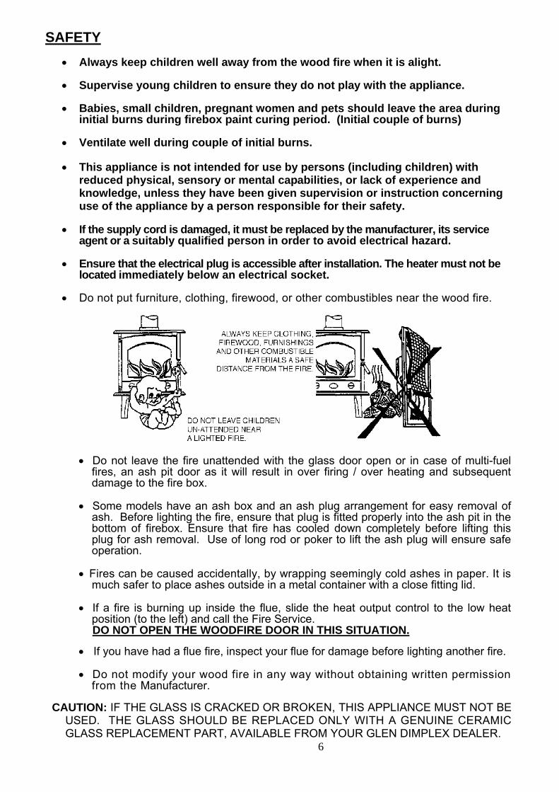
• Do not put furniture, clothing, firewood, or other combustibles near the wood fire.
• Do not leave the fire unattended with the glass door open or in case of multi-fuel fires, an ash pit door as it will result in over firing / over heating and subsequent damage to the fire box.
• Some models have an ash box and an ash plug arrangement for easy removal of ash. Before lighting the fire, ensure that plug is fitted properly into the ash pit in the bottom of firebox. Ensure that fire has cooled down completely before lifting this plug for ash removal. Use of long rod or poker to lift the ash plug will ensure safe operation.
• Fires can be caused accidentally, by wrapping seemingly cold ashes in paper. It is much safer to place ashes outside in a metal container with a close fitting lid.
• If a fire is burning up inside the flue, slide the heat output control to the low heat
position (to the left) and call the Fire Service. DO NOT OPEN THE WOODFIRE DOOR IN THIS SITUATION.
• If you have had a flue fire, inspect your flue for damage before lighting another fire.
• Do not modify your wood fire in any way without obtaining written permission from the Manufacturer.
CAUTION: IF THE GLASS IS CRACKED OR BROKEN, THIS APPLIANCE MUST NOT BE
USED. THE GLASS SHOULD BE REPLACED ONLY WITH A GENUINE CERAMIC GLASS REPLACEMENT PART, AVAILABLE FROM YOUR GLEN DIMPLEX DEALER.
7
MAINTENANCE
ASH REMOVAL
This should be necessary when ash level is upto lower door opening. Simply shovel out any excess, always leaving a bed of ash to the tops of the ribs on the bottom of the cast firebox or 10-15mm in steel firebox. Place the removed ashes in a noncombustible container with a tightly fitting lid, and move the container outdoors immediately to a place clear of combustible materials.
CLEANING THE GLASS A good hot fire will burn away any deposits left from a long slow burn. A dampened newspaper with ash or a non-caustic oven cleaner can be used to clean the glass.
CLEANING THE CABINET OR FASCIA A soft rag is sufficient to clean and maintain the finish of the panels. Household detergent may damage painted panels or give bad odors while running the fire.
ADJUSTING THE DOOR LATCH If the handle is front mounted, the latch can be adjusted to overcome settling of the door gasket by transferring a washer to the outside of the door catch spindle. If the handle is side mounted, the latch is adjusted by rotating the door catch peg. First undo the lock-nut on the inside of the peg, and then rotate the peg to the position where the cam portion gives the right locking pressure. Hold the peg in this position, re-tighten the lock nut. The hinge on all models can also be adjusted inward if necessary. Move it in about a millimetre at top and bottom to maintain an even gasket pressure. Serious leakage will require a new door seal.
HEAT OUTPUT CONTROL (AIR SLIDE) If the air slide does not move freely, have an installer inspect the unit and apply a small amount of heat resistant air slide lubricant, available from Glen Dimplex.
CLEANING INSIDE If you wish to clean the flue or clear away creosote debris, the internal components can be removed easily (See below). We recommend that you check the condition of all internal components at least once a season to make sure they are still serviceable.
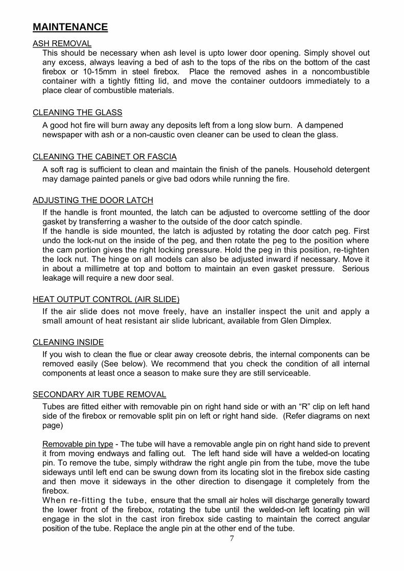
SECONDARY AIR TUBE REMOVAL Tubes are fitted either with removable pin on right hand side or with an “R” clip on left hand side of the firebox or removable split pin on left or right hand side. (Refer diagrams on next page) Removable pin type - The tube will have a removable angle pin on right hand side to prevent it from moving endways and falling out. The left hand side will have a welded-on locating pin. To remove the tube, simply withdraw the right angle pin from the tube, move the tube sideways until left end can be swung down from its locating slot in the firebox side casting and then move it sideways in the other direction to disengage it completely from the firebox. When re-fi t t ing the tube, ensure that the small air holes will discharge generally toward the lower front of the firebox, rotating the tube until the welded-on left locating pin will engage in the slot in the cast iron firebox side casting to maintain the correct angular position of the tube. Replace the angle pin at the other end of the tube.
8
Removable “R” Clip type - The air tube is secured to the left hand side of the fire box with a “R” Clip. Remove the “R” Clip and move the tube to the right, remove the tube from the left hand side of the fire box first. Removable Split Pin type – This air tube is secured to the left hand side of the firebox with a pin that is welded through the air tube. On the right, the spit pin which passes through the air bar horizontally, stops against the cast collar in the side panel casting to stop it moving endways and falling out. Note that the split pin is on left for LE7000 Provincial, F7000, F10000R, Grandview F12000 & I9000 models.
Air Tube Style
Removable Pin Style
“R” Clip Style Removable Split Pin Style
Left Hand End
Right Hand End
FIREBOX TOP BAFFLE. The special top baffle material operates at very high temperature to ensure clean burning. Take care not to knock and damage it. For flue cleaning or baffle replacement the secondary air tube must first be removed as described above. When replacing the baffle, ensure that it is sitting on top of the supporting shelf at each end and that it is pushed right to the back until the front corners drop behind the small retainer ribs on the shelves. Re-fit the secondary air tube in place. Note: Some fires are equipped with steel baffles. Warning: Ensure that secondary air tubes and baffle are correctly repositioned and secured with the correct fasteners prior to relighting the appliance. If you are unsure, consult the manufacturer or authorized service agent.
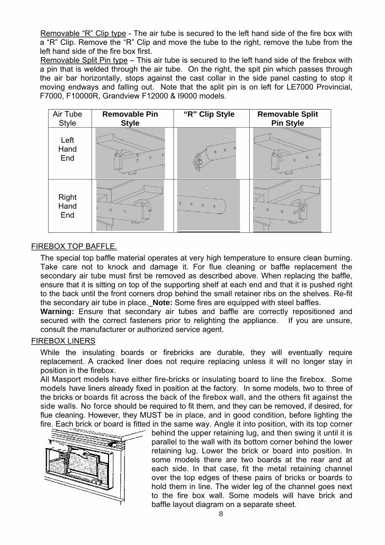
FIREBOX LINERS While the insulating boards or firebricks are durable, they will eventually require replacement. A cracked liner does not require replacing unless it will no longer stay in position in the firebox. All Masport models have either fire-bricks or insulating board to line the firebox. Some models have liners already fixed in position at the factory. In some models, two to three of the bricks or boards fit across the back of the firebox wall, and the others fit against the side walls. No force should be required to fit them, and they can be removed, if desired, for flue cleaning. However, they MUST be in place, and in good condition, before lighting the fire. Each brick or board is fitted in the same way. Angle it into position, with its top corner
behind the upper retaining lug, and then swing it until it is parallel to the wall with its bottom corner behind the lower retaining lug. Lower the brick or board into position. In some models there are two boards at the rear and at each side. In that case, fit the metal retaining channel over the top edges of these pairs of bricks or boards to hold them in line. The wider leg of the channel goes next to the fire box wall. Some models will have brick and baffle layout diagram on a separate sheet.
9
FAN MAINTENANCE
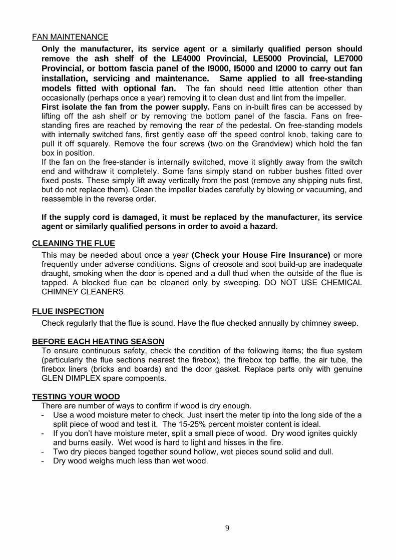
Only the manufacturer, its service agent or a similarly qualified person should remove the ash shelf of the LE4000 Provincial, LE5000 Provincial, LE7000 Provincial, or bottom fascia panel of the I9000, I5000 and I2000 to carry out fan installation, servicing and maintenance. Same applied to all free-standing models fitted with optional fan. The fan should need little attention other than occasionally (perhaps once a year) removing it to clean dust and lint from the impeller. First isolate the fan from the power supply. Fans on in-built fires can be accessed by lifting off the ash shelf or by removing the bottom panel of the fascia. Fans on free-standing fires are reached by removing the rear of the pedestal. On free-standing models with internally switched fans, first gently ease off the speed control knob, taking care to pull it off squarely. Remove the four screws (two on the Grandview) which hold the fan box in position. If the fan on the free-stander is internally switched, move it slightly away from the switch end and withdraw it completely. Some fans simply stand on rubber bushes fitted over fixed posts. These simply lift away vertically from the post (remove any shipping nuts first, but do not replace them). Clean the impeller blades carefully by blowing or vacuuming, and reassemble in the reverse order. If the supply cord is damaged, it must be replaced by the manufacturer, its service agent or similarly qualified persons in order to avoid a hazard.
CLEANING THE FLUE This may be needed about once a year (Check your House Fire Insurance) or more frequently under adverse conditions. Signs of creosote and soot build-up are inadequate draught, smoking when the door is opened and a dull thud when the outside of the flue is tapped. A blocked flue can be cleaned only by sweeping. DO NOT USE CHEMICAL CHIMNEY CLEANERS.
FLUE INSPECTION Check regularly that the flue is sound. Have the flue checked annually by chimney sweep.
BEFORE EACH HEATING SEASON
To ensure continuous safety, check the condition of the following items; the flue system (particularly the flue sections nearest the firebox), the firebox top baffle, the air tube, the firebox liners (bricks and boards) and the door gasket. Replace parts only with genuine GLEN DIMPLEX spare compoents.
TESTING YOUR WOOD There are number of ways to confirm if wood is dry enough. - Use a wood moisture meter to check. Just insert the meter tip into the long side of the a
split piece of wood and test it. The 15-25% percent moister content is ideal. - If you don’t have moisture meter, split a small piece of wood. Dry wood ignites quickly
and burns easily. Wet wood is hard to light and hisses in the fire. - Two dry pieces banged together sound hollow, wet pieces sound solid and dull. - Dry wood weighs much less than wet wood.
10
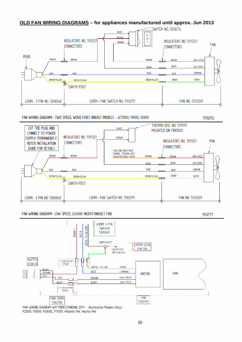
OLD FAN WIRING DIAGRAMS – for appliances manufactured until approx. Jun 2013
11
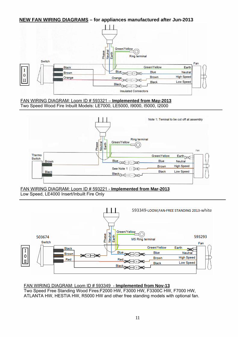
NEW FAN WIRING DIAGRAMS – for appliances manufactured after Jun-2013
FAN WIRING DIAGRAM: Loom ID # 593221 - Implemented from Mar-2013 Low Speed, LE4000 Insert/Inbuilt Fire Only
FAN WIRING DIAGRAM: Loom ID # 593321 – Implemented from May-2013 Two Speed Wood Fire Inbuilt Models: LE7000, LE5000, I9000, I5000, I2000
FAN WIRING DIAGRAM: Loom ID # 593349 - Implemented from Nov-13 Two Speed Free Standing Wood Fires:F2000 HW, F3000 HW, F3300C HW, F7000 HW, ATLANTA HW, HESTIA HW, R5000 HW and other free standing models with optional fan.
12
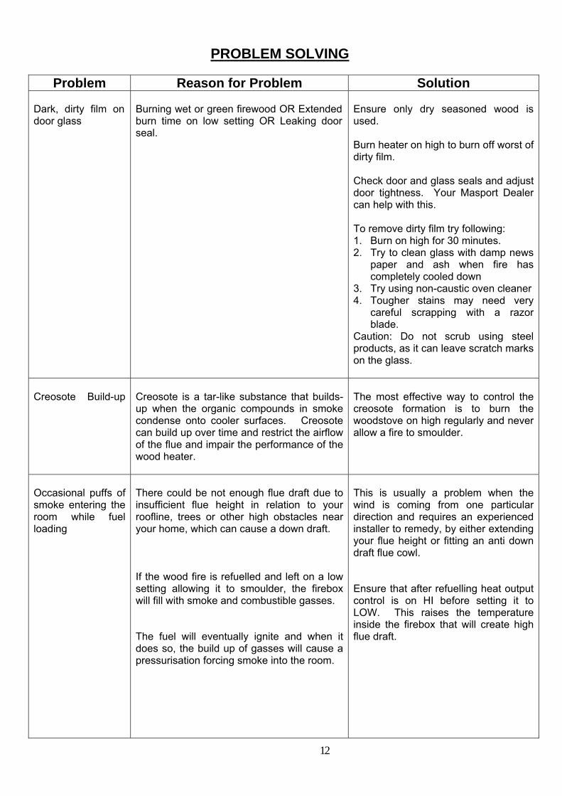
PROBLEM SOLVING
Problem Reason for Problem Solution
Dark, dirty film on door glass
Burning wet or green firewood OR Extended burn time on low setting OR Leaking door seal.
Ensure only dry seasoned wood is used. Burn heater on high to burn off worst of dirty film. Check door and glass seals and adjust door tightness. Your Masport Dealer can help with this. To remove dirty film try following: 1. Burn on high for 30 minutes. 2. Try to clean glass with damp news
paper and ash when fire has completely cooled down
3. Try using non-caustic oven cleaner 4. Tougher stains may need very
careful scrapping with a razor blade.
Caution: Do not scrub using steel products, as it can leave scratch marks on the glass.
Creosote Build-up
Creosote is a tar-like substance that builds-up when the organic compounds in smoke condense onto cooler surfaces. Creosote can build up over time and restrict the airflow of the flue and impair the performance of the wood heater.
The most effective way to control the creosote formation is to burn the woodstove on high regularly and never allow a fire to smoulder.
Occasional puffs of smoke entering the room while fuel loading
There could be not enough flue draft due to insufficient flue height in relation to your roofline, trees or other high obstacles near your home, which can cause a down draft. If the wood fire is refuelled and left on a low setting allowing it to smoulder, the firebox will fill with smoke and combustible gasses. The fuel will eventually ignite and when it does so, the build up of gasses will cause a pressurisation forcing smoke into the room.
This is usually a problem when the wind is coming from one particular direction and requires an experienced installer to remedy, by either extending your flue height or fitting an anti down draft flue cowl. Ensure that after refuelling heat output control is on HI before setting it to LOW. This raises the temperature inside the firebox that will create high flue draft.
13
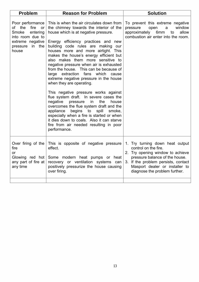
Problem Reason for Problem Solution Poor performance of the fire or Smoke entering into room due to extreme negative pressure in the house
This is when the air circulates down from the chimney towards the interior of the house which is at negative pressure. Energy efficiency practices and new building code rules are making our houses more and more airtight. This makes the house’s energy efficient but also makes them more sensitive to negative pressure when air is exhausted from the house. This can be because of large extraction fans which cause extreme negative pressure in the house when they are operating. This negative pressure works against flue system draft. In severe cases the negative pressure in the house overcomes the flue system draft and the appliance begins to spill smoke, especially when a fire is started or when it dies down to coals. Also it can starve fire from air needed resulting in poor performance.
To prevent this extreme negative pressure open a window approximately 6mm to allow combustion air enter into the room.
Over firing of the fire or Glowing red hot any part of fire at any time
This is opposite of negative pressure effect. Some modern heat pumps or heat recovery or ventilation systems can positively pressurize the house causing over firing.
1. Try turning down heat output
control on the fire. 2. Try opening window to achieve
pressure balance of the house. 3. If the problem persists, contact
Masport dealer or installer to diagnose the problem further.
14
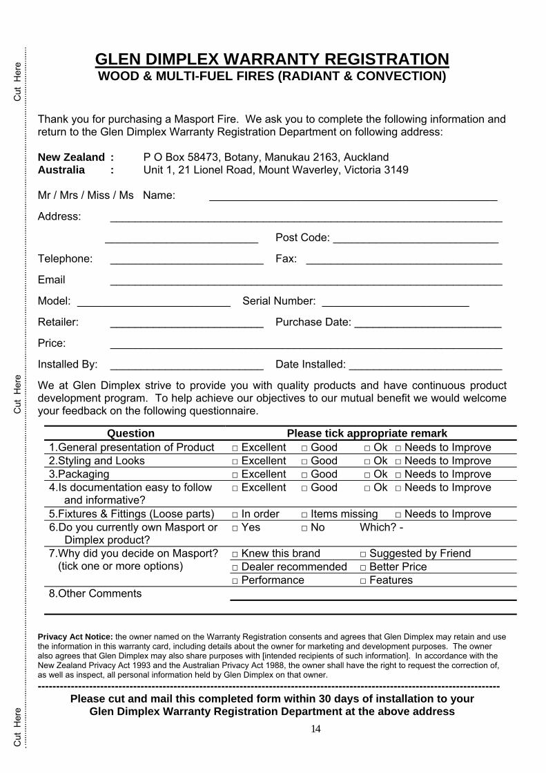
GLEN DIMPLEX WARRANTY REGISTRATION WOOD & MULTI-FUEL FIRES (RADIANT & CONVECTION)
Thank you for purchasing a Masport Fire. We ask you to complete the following information and return to the Glen Dimplex Warranty Registration Department on following address: New Zealand : P O Box 58473, Botany, Manukau 2163, Auckland Australia : Unit 1, 21 Lionel Road, Mount Waverley, Victoria 3149 Mr / Mrs / Miss / Ms Name: _______________________________________________ Address: ________________________________________________________________ _________________________ Post Code: ___________________________ Telephone: _________________________ Fax: ________________________________ Email ________________________________________________________________ Model: _________________________ Serial Number: ________________________ Retailer: _________________________ Purchase Date: ________________________ Price: ________________________________________________________________ Installed By: _________________________ Date Installed: _________________________ We at Glen Dimplex strive to provide you with quality products and have continuous product development program. To help achieve our objectives to our mutual benefit we would welcome your feedback on the following questionnaire.
Question Please tick appropriate remark 1.General presentation of Product □ Excellent □ Good □ Ok □ Needs to Improve 2.Styling and Looks □ Excellent □ Good □ Ok □ Needs to Improve 3.Packaging □ Excellent □ Good □ Ok □ Needs to Improve 4.Is documentation easy to follow
and informative? □ Excellent □ Good □ Ok □ Needs to Improve
5.Fixtures & Fittings (Loose parts) □ In order □ Items missing □ Needs to Improve 6.Do you currently own Masport or Dimplex product?
□ Yes □ No Which? -
7.Why did you decide on Masport? (tick one or more options)
□ Knew this brand □ Suggested by Friend □ Dealer recommended □ Better Price □ Performance □ Features
8.Other Comments
Privacy Act Notice: the owner named on the Warranty Registration consents and agrees that Glen Dimplex may retain and use the information in this warranty card, including details about the owner for marketing and development purposes. The owner also agrees that Glen Dimplex may also share purposes with [intended recipients of such information]. In accordance with the New Zealand Privacy Act 1993 and the Australian Privacy Act 1988, the owner shall have the right to request the correction of, as well as inspect, all personal information held by Glen Dimplex on that owner. ------------------------------------------------------------------------------------------------------------------------------
Please cut and mail this completed form within 30 days of installation to your Glen Dimplex Warranty Registration Department at the above address
Cut
Her
e
C
ut H
ere
C
ut H
ere

15
16
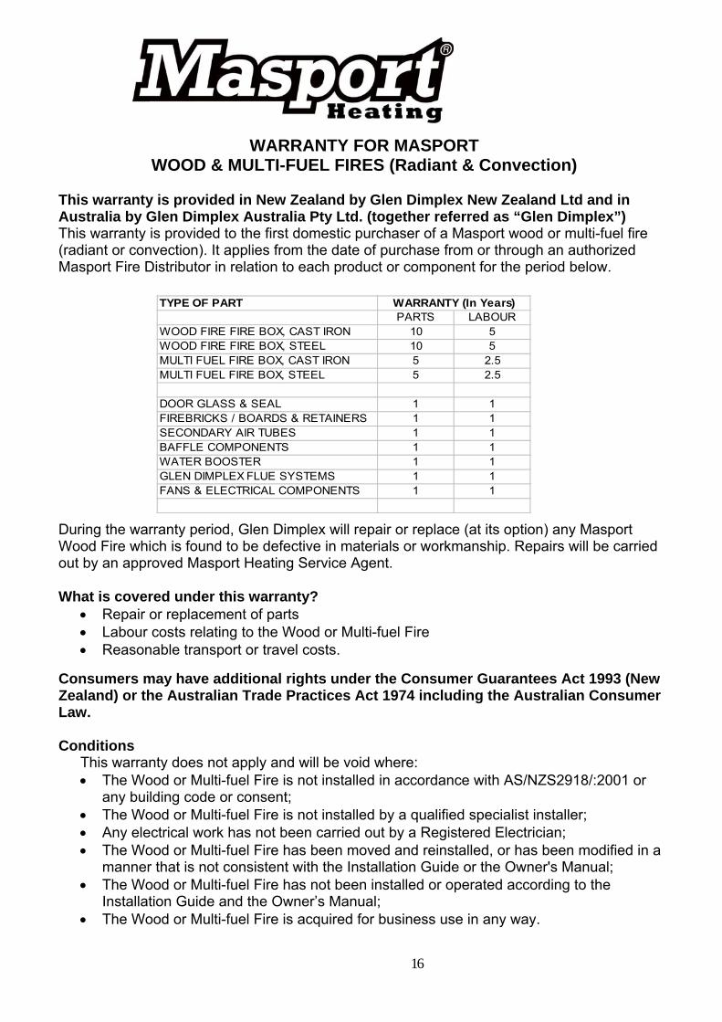
WARRANTY FOR MASPORT WOOD & MULTI-FUEL FIRES (Radiant & Convection)
This warranty is provided in New Zealand by Glen Dimplex New Zealand Ltd and in Australia by Glen Dimplex Australia Pty Ltd. (together referred as “Glen Dimplex”) This warranty is provided to the first domestic purchaser of a Masport wood or multi-fuel fire (radiant or convection). It applies from the date of purchase from or through an authorized Masport Fire Distributor in relation to each product or component for the period below. During the warranty period, Glen Dimplex will repair or replace (at its option) any Masport Wood Fire which is found to be defective in materials or workmanship. Repairs will be carried out by an approved Masport Heating Service Agent. What is covered under this warranty?
• Repair or replacement of parts • Labour costs relating to the Wood or Multi-fuel Fire • Reasonable transport or travel costs.
Consumers may have additional rights under the Consumer Guarantees Act 1993 (New Zealand) or the Australian Trade Practices Act 1974 including the Australian Consumer Law. Conditions
This warranty does not apply and will be void where: • The Wood or Multi-fuel Fire is not installed in accordance with AS/NZS2918/:2001 or
any building code or consent; • The Wood or Multi-fuel Fire is not installed by a qualified specialist installer; • Any electrical work has not been carried out by a Registered Electrician; • The Wood or Multi-fuel Fire has been moved and reinstalled, or has been modified in a
manner that is not consistent with the Installation Guide or the Owner's Manual; • The Wood or Multi-fuel Fire has not been installed or operated according to the
Installation Guide and the Owner’s Manual; • The Wood or Multi-fuel Fire is acquired for business use in any way.
TYPE OF PARTPARTS LABOUR
WOOD FIRE FIRE BOX, CAST IRON 10 5WOOD FIRE FIRE BOX, STEEL 10 5MULTI FUEL FIRE BOX, CAST IRON 5 2.5MULTI FUEL FIRE BOX, STEEL 5 2.5
DOOR GLASS & SEAL 1 1FIREBRICKS / BOARDS & RETAINERS 1 1SECONDARY AIR TUBES 1 1BAFFLE COMPONENTS 1 1WATER BOOSTER 1 1GLEN DIMPLEX FLUE SYSTEMS 1 1FANS & ELECTRICAL COMPONENTS 1 1
WARRANTY (In Years)
17
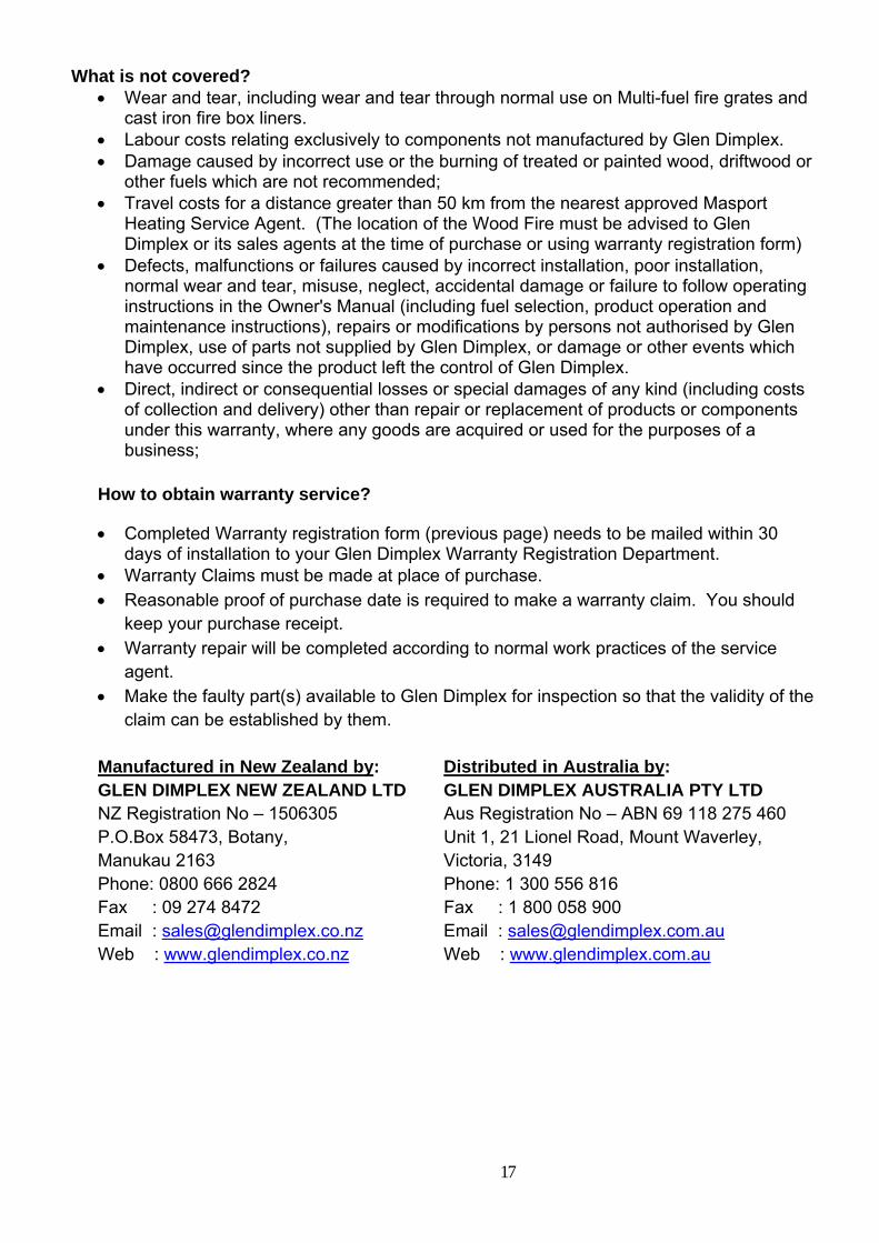
What is not covered?
• Wear and tear, including wear and tear through normal use on Multi-fuel fire grates and cast iron fire box liners.
• Labour costs relating exclusively to components not manufactured by Glen Dimplex. • Damage caused by incorrect use or the burning of treated or painted wood, driftwood or
other fuels which are not recommended; • Travel costs for a distance greater than 50 km from the nearest approved Masport
Heating Service Agent. (The location of the Wood Fire must be advised to Glen Dimplex or its sales agents at the time of purchase or using warranty registration form)
• Defects, malfunctions or failures caused by incorrect installation, poor installation, normal wear and tear, misuse, neglect, accidental damage or failure to follow operating instructions in the Owner's Manual (including fuel selection, product operation and maintenance instructions), repairs or modifications by persons not authorised by Glen Dimplex, use of parts not supplied by Glen Dimplex, or damage or other events which have occurred since the product left the control of Glen Dimplex.
• Direct, indirect or consequential losses or special damages of any kind (including costs of collection and delivery) other than repair or replacement of products or components under this warranty, where any goods are acquired or used for the purposes of a business;
How to obtain warranty service?
• Completed Warranty registration form (previous page) needs to be mailed within 30 days of installation to your Glen Dimplex Warranty Registration Department.
• Warranty Claims must be made at place of purchase. • Reasonable proof of purchase date is required to make a warranty claim. You should
keep your purchase receipt. • Warranty repair will be completed according to normal work practices of the service
agent. • Make the faulty part(s) available to Glen Dimplex for inspection so that the validity of the
claim can be established by them.
Manufactured in New Zealand by: Distributed in Australia by: GLEN DIMPLEX NEW ZEALAND LTD GLEN DIMPLEX AUSTRALIA PTY LTD NZ Registration No – 1506305 Aus Registration No – ABN 69 118 275 460 P.O.Box 58473, Botany, Unit 1, 21 Lionel Road, Mount Waverley, Manukau 2163 Victoria, 3149 Phone: 0800 666 2824 Phone: 1 300 556 816 Fax : 09 274 8472 Fax : 1 800 058 900 Email : [email protected] Email : [email protected] Web : www.glendimplex.co.nz Web : www.glendimplex.com.au