Embed Size (px)
Citation preview

Wolfgang Fritz 01/2012
WM
S4
50
/47
0 M
UL
TIC
HA
NN
EL
SE
TU
P G
UID
ES
CH
EM
AT
IC &
PA
RT
LIS
T 1
-16
CH
AN
NE
L
1
Introduction
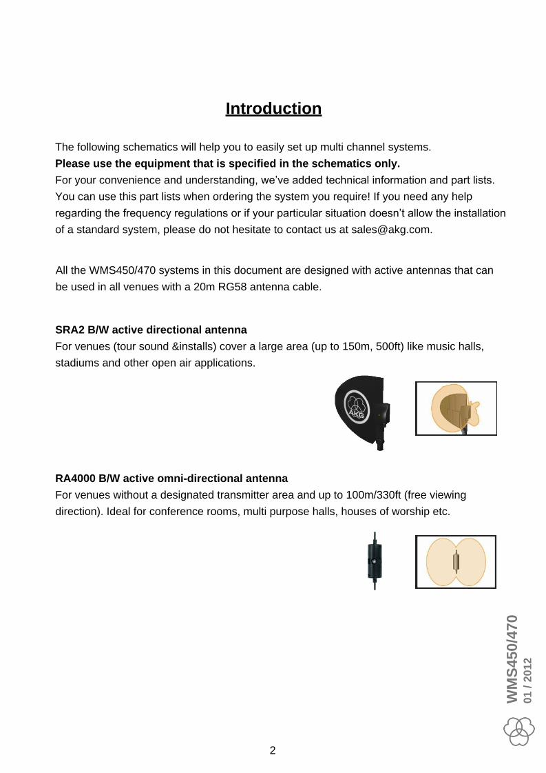
SRA2 B/W active directional antenna
For venues (tour sound &installs) cover a large area (up to 150m, 500ft) like music halls,
stadiums and other open air applications.
RA4000 B/W active omni-directional antenna
For venues without a designated transmitter area and up to 100m/330ft (free viewing
direction). Ideal for conference rooms, multi purpose halls, houses of worship etc.
The following schematics will help you to easily set up multi channel systems.
Please use the equipment that is specified in the schematics only.
For your convenience and understanding, we’ve added technical information and part lists.
You can use this part lists when ordering the system you require! If you need any help
regarding the frequency regulations or if your particular situation doesn’t allow the installation
of a standard system, please do not hesitate to contact us at [email protected].
All the WMS450/470 systems in this document are designed with active antennas that can
be used in all venues with a 20m RG58 antenna cable.
WM
S4
50
/47
00
1 / 2
01
2
2

Content
General Information Page
Receiver/Antenna Placement Information 4
Squelch Information 4
Intermodulation Information 4
Cable Attenuation Information 5
PS4000 dip switch Information 5
AB4000 dip switch Information 5
PS4000 dip Switch Matrix Information 6
Required Component Matrix Information 7
Glossar Information 8
WMS System Antenna Type Page
16 Channel SRA2 B/W
16 Channel RA4000 B/W
SRA2 B/W
RA4000 B/W
SRA2 B/W
RA4000 B/W
2 Channel no PS4000W
2 Channel no PS4000W
1 Channel
Channel1
2
2 Channel no PSU4000 RA4000 B/W
SRA2 B/WChannel no PSU4000
Channel no PSU4000
Channel no PSU4000
SRA2 B/W4
4
Channel no PSU4000
Channel no PSU4000 RA4000 B/W
SRA2 B/W
RA4000 B/W
SRA2 B/W
6 Channel no PSU4000 RA4000 B/W
6 Channel no PSU4000
5
5
10 Channel
8 Channel no PSU4000 SRA2 B/W
8 Channel no PSU4000 RA4000 B/W
10 Channel
SRA2 B/W
RA4000 B/W
SRA2 B/W
RA4000 B/W
Channel no PSU40009
9 Channel no PSU4000
SRA2 B/W
RA4000 B/W
12
12
Channel
Channel
Schematic / Part List
Schematic / Part List
Schematic / Part List
Schematic / Part List
Schematic / Part List
Schematic / Part List
Schematic / Part List
Schematic / Part List
Schematic / Part List
Schematic / Part List
Schematic / Part List
Schematic / Part List
Schematic / Part List
Schematic / Part List
Schematic / Part List
Schematic / Part List
9
11
13
15
17
19
Schematic / Part List
Schematic / Part List
21
23
25
27
Schematic / Part List
Schematic / Part List
Schematic / Part List
Schematic / Part List
41
43
45
47
49
51
29
31
33
35
37
39
WM
S4
50
/47
00
1 / 2
01
2
3

Technical Information
Wireless Basics
Ø Every wireless microphone system has to operate on one specific frequencyØ Transmitter and receiver of a system need to work on the same frequencyØ Two transmitters cannot be used with one receiver at the same time
Receiver/Antenna Placement
Ø Direct line of sight between transmitter and receiver antennaØ Keep the receiver/antennas at least 5 ft. (1.5 m) away from all transmittersØ Keep the receiver antennas at least 5 ft. (1.5 m) away from any big metal object, wire
(particularly wire mesh) or sheet metal structures, walls, ceilings, etc.Ø Do not place the antennas in closed areas (behind walls)Ø Place the receiver at least 5 ft. (1.5 m) away from any equipment that may emit RF
radiation such as lighting racks, fluorescent lamps, digital effect units, or PCs
Squelch
Ø Standard: Carrier squelch, manual– Operates strictly on the signal strength of the signal.
– If received signal strength drops under the adjustable squelch threshold the audio output is muted
Ø Advanced: Tone Code (only WMS470/4500) – The audio turns on only in the presence of the correct tone code and an
adequate signal strength (-100dbm) – Lock out of all signals except ones with the correct key.
Intermodulation
Intermodulation is the result of two or more signals of different frequencies being mixed together, forming additional signals that are not harmonic frequencies of either.
By using more than one transmitter simultaneously at the same location,
intermodulation happens in the receiver and/or transmitter. These intermodulation products are generated in the bandwidth that you are using.
To avoid intermodulating frequencies, we offer pre-calculated frequencies as presets in the SR450 and SR4500 Receiver. Please, make sure that when setting up a multi channel system, all your receivers are set to the same country preset (NAME) and group. Use the automatic channel function (auto setup) to scan for free frequencies in your venue.
WM
S4
50
/47
00
1 / 2
01
2
4

RG58 Cable Attenuation (MKPS, MKA5, MKA20 antenna cable)
Cable Attenuation
To obtain the best sound possible, you need to have the right RF input level throughout your signal chain. Premium quality wireless systems like the WMS450/470 and WMS4500, offer you adjustable RF-level settings that garantee to maximise operating distance even when using different cable lenghts and different types of cable! For this purpose, AKG’s PS4000W antenna splitter, has 3 dip switches that you’ll find on the right side of it’s front panel, behind the AKG logo.
PS4000 W dip switch
These switches reduce the input RF level of the antenna input between 0 dB and 14 dB.
Levels of all antenna outputs and the cascade (link) output will be reduced.
AB4000 dip switch
The AB4000 has a fix 17.5dB amplifier in the output stage. The dip switches reduce the input RF level of the AB4000 from 0 dB and -14 dB. AB4000 gets the DC power from the PS4000W or an ASU4000 unit via the antenna cable
Rear View
4x Antenna A output (DC power)
Antenna A input Ant. B
Antenna A cascade output
(DC power)
dip switches behind AKG Logo
Signal level adjustment
Attenuation
PS4000W – Power Splitter
AB4000 – Antenna BoosterSignal level adjustment
Internal Attenuation
Total Gain
3.5 dB
5.5 dB
7.5 dB
9.5 dB
11.5 dB
13.5 dB
15.5 dB
17.5 dB
WM
S4
50
/47
00
1 / 2
01
2
5

3x MKA 20
60m / 198ft
Antenna Booster
AB4000
necessary !
4x MKA 20
80m / 264ft
Antenna Booster
AB4000
necessary !
MKA 5
5m / 16ft
MKA 20
20m / 66ft
MKA 5 + MKA 20
25m / 82ft
2x MKA 20
40m / 132ft
Cable type
&
Length
MKPS
0.65m / 2ft
PS4000 W dip switch matrix (RG58 cable)
RA4000 W SRA2 W RA4000 BW SRA2 BW
Passiv Antennas Active Antennas
Antenna type
&
Gain
0 dB
0 dB 0 dB -4 dB
0 dB -2 dB
-8 dB -12 dB
-6 dB -10 dB
0 dB
0 dB -2 dB
RA4000 BW
2x MKA 20
AB4000
0 dB
PS4000
-4 dB
1x MKA 20
SRA2 BW
2x MKA 20
AB4000
0 dB
PS4000
-8 dB
1x MKA 20
RA4000 BW
2x MKA 20
AB4000
0 dB
PS4000
0 dB
2x MKA 20
SRA2 BW
2x MKA 20
AB4000
0 dB
PS4000
0 dB
2x MKA 20
1 dB 4-6 dB 17 dB 21.5 dB
¼ wave
UHF Antenna
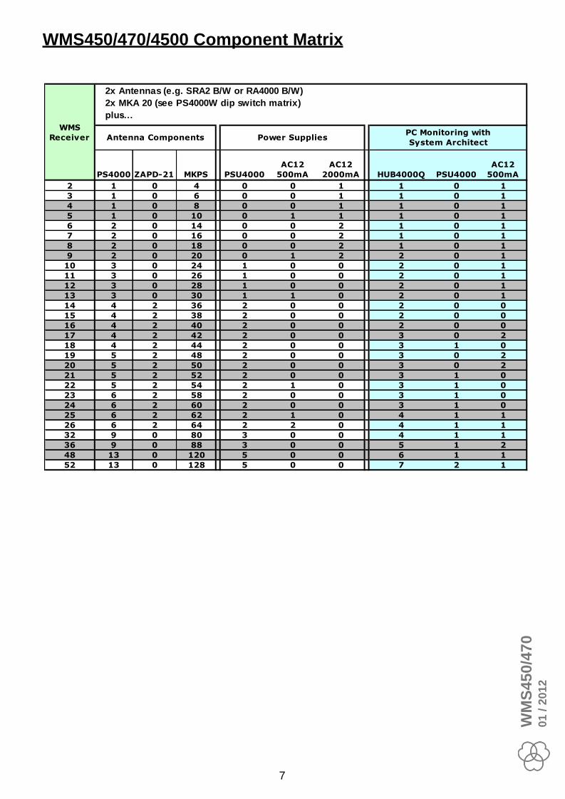
You have to use these PS4000 W dip switch settings for all PS4000 W directly connected to antennas.
All PS4000 W connected to a PS4000 W link output (cascade) have dip switch setting ON/ON/ON (0dB)
WM
S4
50
/47
00
1 / 2
01
2
6
PS4000 ZAPD-21 MKPS PSU4000
AC12
500mA
AC12
2000mA HUB4000Q PSU4000
AC12
500mA
2 1 0 4 0 0 1 1 0 1
3 1 0 6 0 0 1 1 0 1
4 1 0 8 0 0 1 1 0 1
5 1 0 10 0 1 1 1 0 1
6 2 0 14 0 0 2 1 0 1
7 2 0 16 0 0 2 1 0 1
8 2 0 18 0 0 2 1 0 1
9 2 0 20 0 1 2 2 0 1
10 3 0 24 1 0 0 2 0 1
11 3 0 26 1 0 0 2 0 1
12 3 0 28 1 0 0 2 0 1
13 3 0 30 1 1 0 2 0 1
14 4 2 36 2 0 0 2 0 0
15 4 2 38 2 0 0 2 0 0
16 4 2 40 2 0 0 2 0 0
17 4 2 42 2 0 0 3 0 2
18 4 2 44 2 0 0 3 1 0
19 5 2 48 2 0 0 3 0 2
20 5 2 50 2 0 0 3 0 2
21 5 2 52 2 0 0 3 1 0
22 5 2 54 2 1 0 3 1 0
23 6 2 58 2 0 0 3 1 0
24 6 2 60 2 0 0 3 1 0
25 6 2 62 2 1 0 4 1 1
26 6 2 64 2 2 0 4 1 1
32 9 0 80 3 0 0 4 1 1
36 9 0 88 3 0 0 5 1 2
48 13 0 120 5 0 0 6 1 1
52 13 0 128 5 0 0 7 2 1
WMS
Receiver Power SuppliesPC Monitoring with
System ArchitectAntenna Components
2x Antennas (e.g. SRA2 B/W or RA4000 B/W)
2x MKA 20 (see PS4000W dip switch matrix)
plus…
WMS450/470/4500 Component Matrix
WM
S4
50
/47
00
1 / 2
01
2
7

Glossar
SR450/470 – WMS450 or WMS470 Stationary Receiver
PS4000W – Power Splitter 1:4 (Distribute RF signal and DC Power)
● Splits 1 antenna to 4 receiver
● Antenna cascade(Link) output to send RF-Signal to next PS4000.
Cascade max. 3 PS4000.
If you need more than 12 channels use an ZAPD in front of the first PS4000.
PSU4000 – Power Supply Unit with 3x 12 volt outputs (2.5A and 2A)
SRA2 B/W – Active Directional Antenna (21.5 dB Gain)
RA4000 B/W – Active Omni-directional Antenna (17 dB Gain)
CU400 – Charging Unit for WMS450/470 (2 transmitter / unit)
ZAPD-21 – Passive Combiner 2:1 and 1:2
MKPS – 0.65m/2 feet RG58 antenna cable
MKA20 – 20/66ft RG58 antenna cable
ASU4000 – Antenna Supply Unit
● Supplies up to three active elements (RA4000BW, SRA2BW, AB4000)
0110E01890 – Front mount cable
● Install ¼ wave antennas at the front of the rack
AB4000 – Antenna Booster
● 3.5 dB – 17.5 dB amplifier
Front mount cable & ¼ wave antenna
Cable
MKA5 – 5m/16ft RG58 antenna cable
1A
1B
2A
2B
3A
3B
4B
4A
ANT A IN ANT B IN
DC IN (12V/0.5A)
PS4000WCASCADE A
CASCADE B
DC OUT 1 (2.5A)
AC POWER
PSU4000
DC OUT 2 (2A)
DC OUT 3 (2A)~90-230V
SRA2 B/W
ANT OUT
RA4000 B/W
ANT OUT
ZAPD-21
A
S
B
ASU4000
ANT OUT
ANT IN
DC IN (12V/0.5A)
AB4000
ANT OUT
ANT IN
WM
S4
50
/47
00
1 / 2
01
2
SR450/470
XLR
AUDIO OUT
ANT A IN
DC IN (12V/0.5A)
¼“ TS
AUDIO OUT
ANT B IN
▼
Mixer
DATA
LOGIC OUT
CU400
DC IN (5V/1.4A)
8
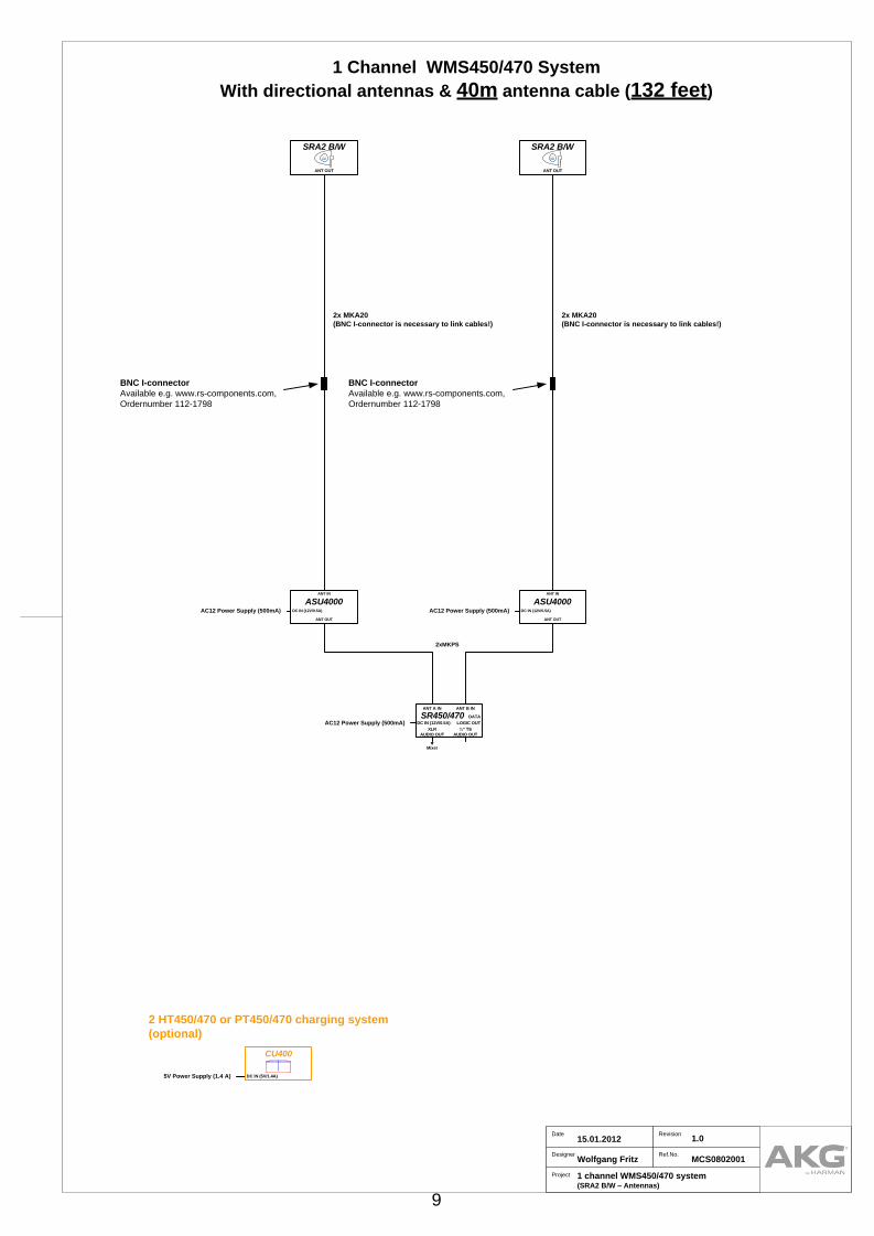
2 HT450/470 or PT450/470 charging system
(optional)
Project
Designer
Date Revision
1 channel WMS450/470 system (SRA2 B/W – Antennas)
Wolfgang Fritz
15.01.2012 1.0
Ref.No.MCS0802001
1 Channel WMS450/470 System
With directional antennas & 40m antenna cable (132 feet)
AC12 Power Supply (500mA)
ASU4000
ANT OUT
ANT IN
DC IN (12V/0.5A)AC12 Power Supply (500mA)
ASU4000
ANT OUT
ANT IN
DC IN (12V/0.5A)AC12 Power Supply (500mA)
2xMKPS
BNC I-connector
Available e.g. www.rs-components.com,
Ordernumber 112-1798
BNC I-connector
Available e.g. www.rs-components.com,
Ordernumber 112-1798
2x MKA20
(BNC I-connector is necessary to link cables!)
2x MKA20
(BNC I-connector is necessary to link cables!)
SRA2 B/W
ANT OUT
SRA2 B/W
ANT OUT
SR450/470
XLR
AUDIO OUT
ANT A IN
DC IN (12V/0.5A)
¼“ TS
AUDIO OUT
ANT B IN
▼
Mixer
DATA
LOGIC OUT
5V Power Supply (1.4 A)
CU400
DC IN (5V/1.4A)
9
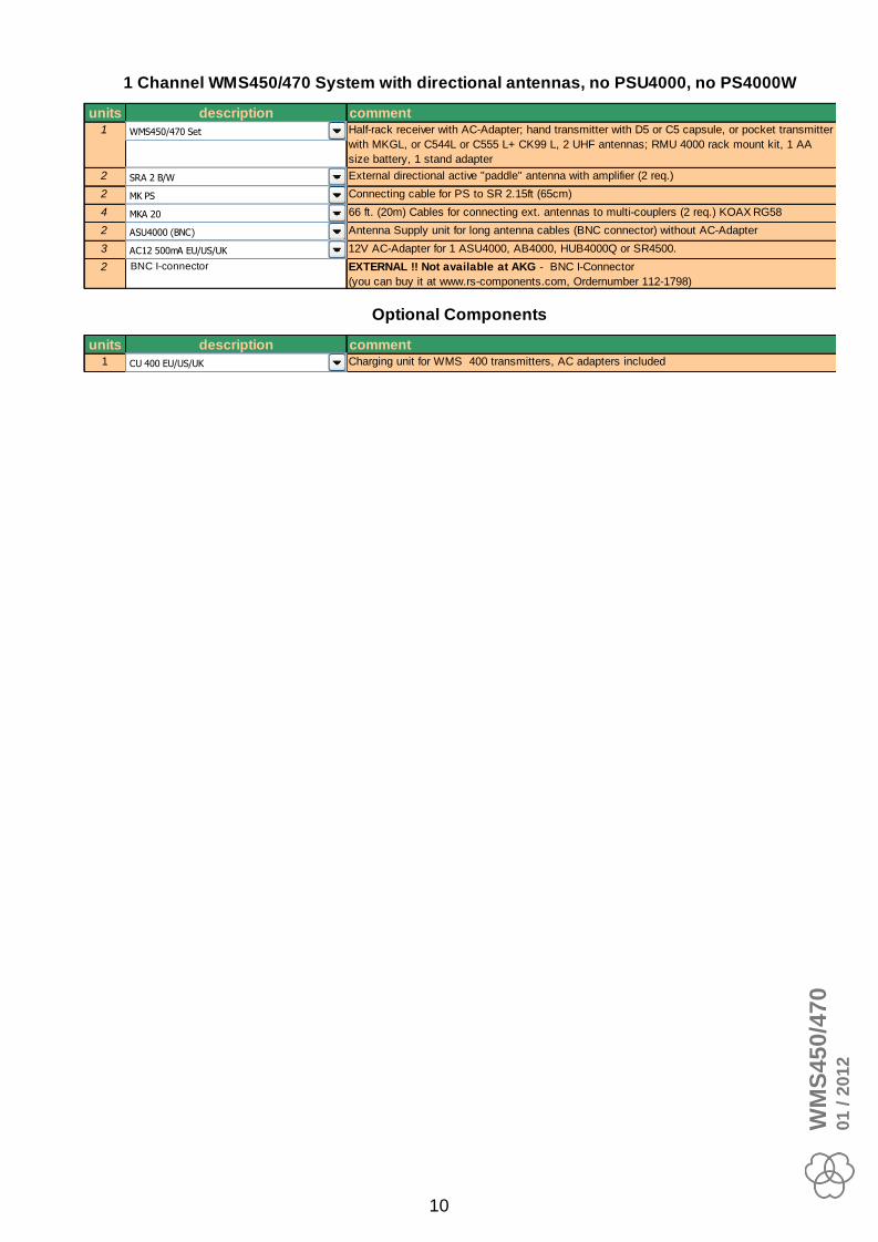
units description comment1 18 Half-rack receiver with AC-Adapter; hand transmitter with D5 or C5 capsule, or pocket transmitter
with MKGL, or C544L or C555 L+ CK99 L, 2 UHF antennas; RMU 4000 rack mount kit, 1 AA
size battery, 1 stand adapter
2 72 External directional active "paddle" antenna with amplifier (2 req.)
2 54 Connecting cable for PS to SR 2.15ft (65cm)
4 55 66 ft. (20m) Cables for connecting ext. antennas to multi-couplers (2 req.) KOAX RG58
2 10 Antenna Supply unit for long antenna cables (BNC connector) without AC-Adapter
3 4 12V AC-Adapter for 1 ASU4000, AB4000, HUB4000Q or SR4500.
2 BNC I-connector EXTERNAL !! Not available at AKG - BNC I-Connector
(you can buy it at www.rs-components.com, Ordernumber 112-1798)
units description comment1 35 Charging unit for WMS 400 transmitters, AC adapters included
1 Channel WMS450/470 System with directional antennas, no PSU4000, no PS4000W
Optional Components
CU 400 EU/US/UK
SRA 2 B/W
WMS450/470 Set
MK PS
MKA 20
ASU4000 (BNC)
AC12 500mA EU/US/UK
WM
S4
50
/47
00
1 / 2
01
2
10

2 HT450/470 or PT450/470 charging system
(optional)
Project
Designer
Date Revision
1 channel WMS450/470 system (RA4000 B/W – Antennas)
Wolfgang Fritz
15.01.2012 1.0
Ref.No.MCS0802001
1 Channel WMS450/470 System
with omni-directional antennas & 25m antenna cable (82 feet)
AC12 Power Supply (500mA)
RA4000 B/W
ANT OUT
RA4000 B/W
ANT OUT
ASU4000
ANT OUT
ANT IN
DC IN (12V/0.5A)AC12 Power Supply (500mA)
ASU4000
ANT OUT
ANT IN
DC IN (12V/0.5A)AC12 Power Supply (500mA)
2xMKPS
BNC I-connector
Available e.g. www.rs-components.com,
Ordernumber 112-1798
BNC I-connector
Available e.g. www.rs-components.com,
Ordernumber 112-1798
1x MKA20 + 1x MKA5
(BNC I-connector is necessary to link cables!)
1x MKA20 + 1x MKA5
(BNC I-connector is necessary to link cables!)
SR450/470
XLR
AUDIO OUT
ANT A IN
DC IN (12V/0.5A)
¼“ TS
AUDIO OUT
ANT B IN
▼
Mixer
DATA
LOGIC OUT
5V Power Supply (1.4 A)
CU400
DC IN (5V/1.4A)
11

units description comment1 18 Half-rack receiver with AC-Adapter; hand transmitter with D5 or C5 capsule, or pocket transmitter
with MKGL, or C544L or C555 L+ CK99 L, 2 UHF antennas; RMU 4000 rack mount kit, 1 AA
size battery, 1 stand adapter
2 66 External omni-directional active dipoleantenna with amplifier (2 req.)
2 54 Connecting cable for PS to SR 2.15ft (65cm)
2 55 66 ft. (20m) Cables for connecting ext. antennas to multi-couplers (2 req.) KOAX RG58
2 56 16.5 ft. (5m) Cables for connecting ext. antennas to multi-couplers (2 req.) KOAX RG58
2 10 Antenna Supply unit for long antenna cables (BNC connector) without AC-Adapter
3 4 12V AC-Adapter for 1 ASU4000, AB4000, HUB4000Q or SR4500.
2 BNC I-connector EXTERNAL !! Not available at AKG - BNC I-Connector
(you can buy it at www.rs-components.com, Ordernumber 112-1798)
units description comment1 35 Charging unit for WMS 400 transmitters, AC adapters included
1 Channel WMS450/470 System with omni-directional antennas, no PSU4000, no PS4000W
Optional Components
CU 400 EU/US/UK
RA4000 B/W
MK PS
MKA 20
ASU4000 (BNC)
AC12 500mA EU/US/UK
WMS450/470 Set
MKA 5
WM
S4
50
/47
00
1 / 2
01
2
12

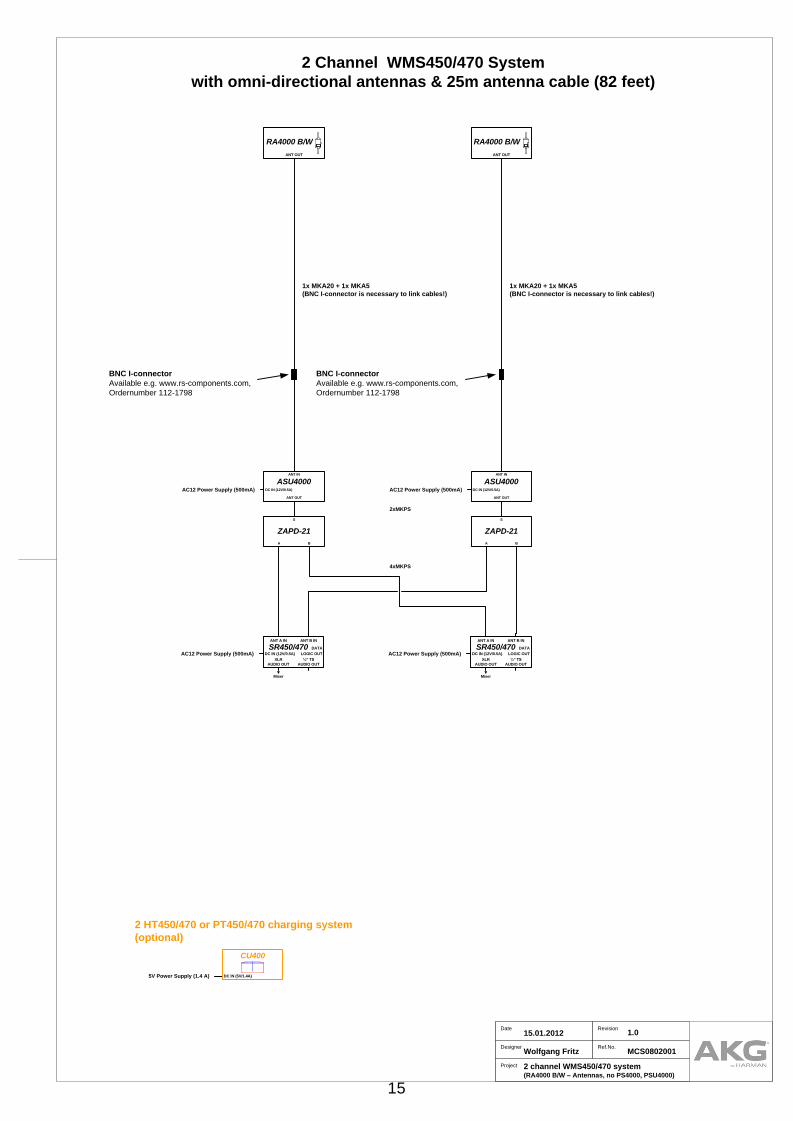
2 HT450/470 or PT450/470 charging system
(optional)
Project
Designer
Date Revision
2 channel WMS450/470 system (SRA2 B/W – Antennas, no PS4000, PSU4000)
Wolfgang Fritz
15.01.2012 1.0
Ref.No.MCS0802001
4xMKPS
2 Channel WMS450/470 System
With directional antennas & 40m antenna cable (132 feet)
AC12 Power Supply (500mA) AC12 Power Supply (500mA)
ZAPD-21
A
S
B
ZAPD-21
A
S
B
ASU4000
ANT OUT
ANT IN
DC IN (12V/0.5A)AC12 Power Supply (500mA)
ASU4000
ANT OUT
ANT IN
DC IN (12V/0.5A)AC12 Power Supply (500mA)
2xMKPS
BNC I-connector
Available e.g. www.rs-components.com,
Ordernumber 112-1798
BNC I-connector
Available e.g. www.rs-components.com,
Ordernumber 112-1798
2x MKA20
(BNC I-connector is necessary to link cables!)
2x MKA20
(BNC I-connector is necessary to link cables!)
SRA2 B/W
ANT OUT
SRA2 B/W
ANT OUT
SR450/470
XLR
AUDIO OUT
ANT A IN
DC IN (12V/0.5A)
¼“ TS
AUDIO OUT
ANT B IN
▼
Mixer
DATA
LOGIC OUT
SR450/470
XLR
AUDIO OUT
ANT A IN
DC IN (12V/0.5A)
¼“ TS
AUDIO OUT
ANT B IN
▼
Mixer
DATA
LOGIC OUT
5V Power Supply (1.4 A)
CU400
DC IN (5V/1.4A)
13

units description comment2 18 Half-rack receiver with AC-Adapter; hand transmitter with D5 or C5 capsule, or pocket transmitter
with MKGL, or C544L or C555 L+ CK99 L, 2 UHF antennas; RMU 4000 rack mount kit, 1 AA
size battery, 1 stand adapter
2 72 External directional active "paddle" antenna with amplifier (2 req.)
6 54 Connecting cable for PS to SR 2.15ft (65cm)
4 55 66 ft. (20m) Cables for connecting ext. antennas to multi-couplers (2 req.) KOAX RG58
2 10 Antenna Supply unit for long antenna cables (BNC connector) without AC-Adapter
4 4 12V AC-Adapter for 1 ASU4000, AB4000, HUB4000Q or SR4500.
2 88 passive power combiner (2in 1out) or Splitter (1in 2out)
2 BNC I-connector EXTERNAL !! Not available at AKG - BNC I-Connector
(you can buy it at www.rs-components.com, Ordernumber 112-1798)
units description comment1 35 Charging unit for WMS 400 transmitters, AC adapters included
2 Channel WMS450/470 System with directional antennas, no PSU4000, no PS4000
Optional Components
CU 400 EU/US/UK
SRA 2 B/W
MK PS
MKA 20
ASU4000 (BNC)
AC12 500mA EU/US/UK
ZAPD21
WMS450/470 Set
WM
S4
50
/47
00
1 / 2
01
2
14
2 HT450/470 or PT450/470 charging system
(optional)
Project
Designer
Date Revision
2 channel WMS450/470 system (RA4000 B/W – Antennas, no PS4000, PSU4000)
Wolfgang Fritz
15.01.2012 1.0
Ref.No.MCS0802001
4xMKPS
2 Channel WMS450/470 System
with omni-directional antennas & 25m antenna cable (82 feet)
AC12 Power Supply (500mA) AC12 Power Supply (500mA)
RA4000 B/W
ANT OUT
RA4000 B/W
ANT OUT
ZAPD-21
A
S
B
ZAPD-21
A
S
B
ASU4000
ANT OUT
ANT IN
DC IN (12V/0.5A)AC12 Power Supply (500mA)
ASU4000
ANT OUT
ANT IN
DC IN (12V/0.5A)AC12 Power Supply (500mA)
2xMKPS
BNC I-connector
Available e.g. www.rs-components.com,
Ordernumber 112-1798
BNC I-connector
Available e.g. www.rs-components.com,
Ordernumber 112-1798
1x MKA20 + 1x MKA5
(BNC I-connector is necessary to link cables!)
1x MKA20 + 1x MKA5
(BNC I-connector is necessary to link cables!)
SR450/470
XLR
AUDIO OUT
ANT A IN
DC IN (12V/0.5A)
¼“ TS
AUDIO OUT
ANT B IN
▼
Mixer
DATA
LOGIC OUT
SR450/470
XLR
AUDIO OUT
ANT A IN
DC IN (12V/0.5A)
¼“ TS
AUDIO OUT
ANT B IN
▼
Mixer
DATA
LOGIC OUT
5V Power Supply (1.4 A)
CU400
DC IN (5V/1.4A)
15

units description comment2 18 Half-rack receiver with AC-Adapter; hand transmitter with D5 or C5 capsule, or pocket transmitter
with MKGL, or C544L or C555 L+ CK99 L, 2 UHF antennas; RMU 4000 rack mount kit, 1 AA
size battery, 1 stand adapter
2 66 External omni-directional active dipoleantenna with amplifier (2 req.)
6 54 Connecting cable for PS to SR 2.15ft (65cm)
2 55 66 ft. (20m) Cables for connecting ext. antennas to multi-couplers (2 req.) KOAX RG58
2 56 16.5 ft. (5m) Cables for connecting ext. antennas to multi-couplers (2 req.) KOAX RG58
2 10 Antenna Supply unit for long antenna cables (BNC connector) without AC-Adapter
4 4 12V AC-Adapter for 1 ASU4000, AB4000, HUB4000Q or SR4500.
2 88 passive power combiner (2in 1out) or Splitter (1in 2out)
2 BNC I-connector EXTERNAL !! Not available at AKG - BNC I-Connector
(you can buy it at www.rs-components.com, Ordernumber 112-1798)
units description comment1 35 Charging unit for WMS 400 transmitters, AC adapters included
2 Channel WMS450/470 System with omni-directional antennas, no PSU4000, no PS4000
Optional Components
RA4000 B/W
MK PS
MKA 20
CU 400 EU/US/UK
ASU4000 (BNC)
AC12 500mA EU/US/UK
ZAPD21
MKA 5
WMS450/470 Set
WM
S4
50
/47
00
1 / 2
01
2
16

2 HT450/470 or PT450/470 charging system
(optional)
Project
Designer
Date Revision
2 channel WMS450/470 system
(SRA2 B/W – Antennas, no PSU4000)
Wolfgang Fritz
15.01.2012 1.0
Ref.No.MCS0802001
MKA20MKA20
4xMKPS
2 Channel WMS450/470 System
with directional antennas & 20(40)m antenna cable (66 or 132 feet)
40m / 132 ft Version:
2x MKA20
BNC I-connector is necessary to link cables!
Available e.g. www.rs-components.com,
Ordernumber 112-1798
Rear View
4x Antenna A output (DC power)
Antenna A input Ant. B
Antenna A cascade output
(DC power)
dip switches behind AKG Logo
Signal level adjustment
Attenuation
PS4000W – Power Splitter
1A
1B
2A
2B
3A
3B
4B
4A
ANT A IN ANT B IN
DC IN (12V/0.5A)
PS4000WCASCADE A
CASCADE B
SRA2 B/W
ANT OUT
SRA2 B/W
ANT OUT
AC12 2000mA Power Supply (2A) (recommend) or
AC12 1500mA Power Supply (1.5A)
2xMKA20
(40m Cable)
1xMKA20
(20m Cable)
-12dBup
down
-2dB
SR450/470
XLR
AUDIO OUT
ANT A IN
DC IN (12V/0.5A)
¼“ TS
AUDIO OUT
ANT B IN
▼
Mixer
DATA
LOGIC OUT
SR450/470
XLR
AUDIO OUT
ANT A IN
DC IN (12V/0.5A)
¼“ TS
AUDIO OUT
ANT B IN
▼
Mixer
DATA
LOGIC OUT
5V Power Supply (1.4 A)
CU400
DC IN (5V/1.4A)
17
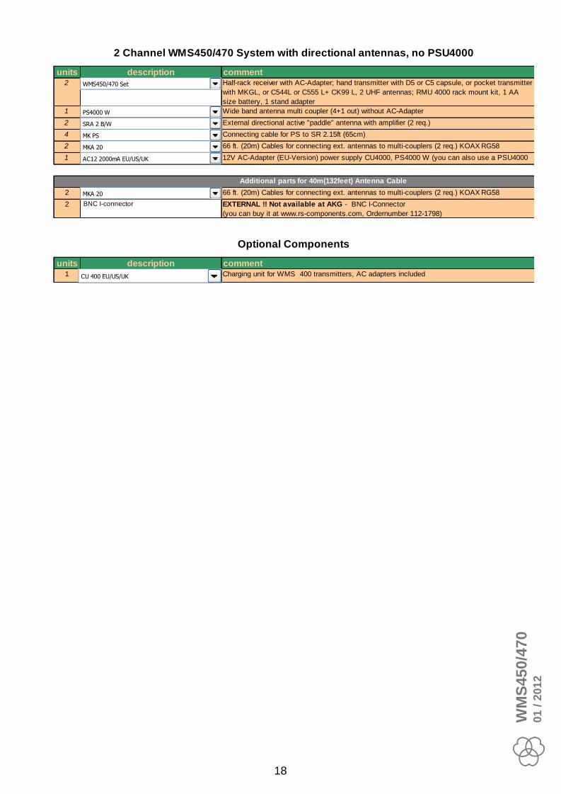
units description comment2 18 Half-rack receiver with AC-Adapter; hand transmitter with D5 or C5 capsule, or pocket transmitter
with MKGL, or C544L or C555 L+ CK99 L, 2 UHF antennas; RMU 4000 rack mount kit, 1 AA
size battery, 1 stand adapter
1 59 Wide band antenna multi coupler (4+1 out) without AC-Adapter
2 72 External directional active "paddle" antenna with amplifier (2 req.)
4 54 Connecting cable for PS to SR 2.15ft (65cm)
2 55 66 ft. (20m) Cables for connecting ext. antennas to multi-couplers (2 req.) KOAX RG58
1 8 12V AC-Adapter (EU-Version) power supply CU4000, PS4000 W (you can also use a PSU4000
output)
2 55 66 ft. (20m) Cables for connecting ext. antennas to multi-couplers (2 req.) KOAX RG58
2 BNC I-connector EXTERNAL !! Not available at AKG - BNC I-Connector
(you can buy it at www.rs-components.com, Ordernumber 112-1798)
units description comment1 35 Charging unit for WMS 400 transmitters, AC adapters included
2 Channel WMS450/470 System with directional antennas, no PSU4000
Optional Components
Additional parts for 40m(132feet) Antenna Cable
CU 400 EU/US/UK
SRA 2 B/W
PS4000 W
MK PS
MKA 20
AC12 2000mA EU/US/UK
MKA 20
WMS450/470 Set
WM
S4
50
/47
00
1 / 2
01
2
18

2 HT450/470 or PT450/470 charging system
(optional)
Project
Designer
Date Revision
2 channel WMS450/470 system
(RA4000 B/W – Antennas, no PSU4000)
Wolfgang Fritz
15.01.2012 1.0
Ref.No.MCS0802001
MKA20MKA20
4xMKPS
2 Channel WMS450/470 System
with omni-directional antennas & 20(40)m antenna cable (66 or 132 feet)
40m / 132 ft Version:
2x MKA20
BNC I-connector is necessary to link cables!
Available e.g. www.rs-components.com,
Ordernumber 112-1798
Rear View
4x Antenna A output (DC power)
Antenna A input Ant. B
Antenna A cascade output
(DC power)
dip switches behind AKG Logo
Signal level adjustment
Attenuation
PS4000W – Power Splitter
1A
1B
2A
2B
3A
3B
4B
4A
ANT A IN ANT B IN
DC IN (12V/0.5A)
PS4000WCASCADE A
CASCADE B
RA4000 B/W
ANT OUT
RA4000 B/W
ANT OUT
AC12 2000mA Power Supply (2A) (recommend) or
AC12 1500mA Power Supply (1.5A)
2xMKA20
(40m Cable)
1xMKA20
(20m Cable)
-8dBup
down
0dB
SR450/470
XLR
AUDIO OUT
ANT A IN
DC IN (12V/0.5A)
¼“ TS
AUDIO OUT
ANT B IN
▼
Mixer
DATA
LOGIC OUT
SR450/470
XLR
AUDIO OUT
ANT A IN
DC IN (12V/0.5A)
¼“ TS
AUDIO OUT
ANT B IN
▼
Mixer
DATA
LOGIC OUT
5V Power Supply (1.4 A)
CU400
DC IN (5V/1.4A)
19

units description comment2 18 Half-rack receiver with AC-Adapter; hand transmitter with D5 or C5 capsule, or pocket transmitter
with MKGL, or C544L or C555 L+ CK99 L, 2 UHF antennas; RMU 4000 rack mount kit, 1 AA
size battery, 1 stand adapter
1 59 Wide band antenna multi coupler (4+1 out) without AC-Adapter
2 66 External omni-directional active dipoleantenna with amplifier (2 req.)
4 54 Connecting cable for PS to SR 2.15ft (65cm)
2 55 66 ft. (20m) Cables for connecting ext. antennas to multi-couplers (2 req.) KOAX RG58
1 8 12V AC-Adapter (EU-Version) power supply CU4000, PS4000 W (you can also use a PSU4000
output)
2 55 66 ft. (20m) Cables for connecting ext. antennas to multi-couplers (2 req.) KOAX RG58
2 BNC I-connector EXTERNAL !! Not available at AKG - BNC I-Connector
(you can buy it at www.rs-components.com, Ordernumber 112-1798)
units description comment1 35 Charging unit for WMS 400 transmitters, AC adapters included
2 Channel WMS450/470 System with omni-directional antennas, no PSU4000
Optional Components
Additional parts for 40m(132feet) Antenna Cable
CU 400 EU/US/UK
RA4000 B/W
PS4000 W
MK PS
MKA 20
AC12 2000mA EU/US/UK
MKA 20
WMS450/470 Set
WM
S4
50
/47
00
1 / 2
01
2
20

4 HT450/470 or PT450/470 charging system
(optional)
Project
Designer
Date Revision
4 channel WMS450/470 system
(SRA2 B/W – Antennas, no PSU4000)
Wolfgang Fritz
15.01.2012 1.0
Ref.No.MCS0802001
MKA20MKA20
8xMKPS
4 Channel WMS450/470 System
with directional antennas & 20(40)m antenna cable (66 or 132 feet)
40m / 132 ft Version:
2x MKA20
BNC I-connector is necessary to link cables!
Available e.g. www.rs-components.com,
Ordernumber 112-1798
Rear View
4x Antenna A output (DC power)
Antenna A input Ant. B
Antenna A cascade output
(DC power)
dip switches behind AKG Logo
Signal level adjustment
Attenuation
PS4000W – Power Splitter
1A
1B
2A
2B
3A
3B
4B
4A
ANT A IN ANT B IN
DC IN (12V/0.5A)
PS4000WCASCADE A
CASCADE B
SRA2 B/W
ANT OUT
SRA2 B/W
ANT OUT
2xMKA20
(40m Cable)
1xMKA20
(20m Cable)
-12dBup
down
-2dB
AC12 2000mA Power Supply (2A)
SR450/470
XLR
AUDIO OUT
ANT A IN
DC IN (12V/0.5A)
¼“ TS
AUDIO OUT
ANT B IN
▼
Mixer
DATA
LOGIC OUT
SR450/470
XLR
AUDIO OUT
ANT A IN
DC IN (12V/0.5A)
¼“ TS
AUDIO OUT
ANT B IN
▼
Mixer
DATA
LOGIC OUT
SR450/470
XLR
AUDIO OUT
ANT A IN
DC IN (12V/0.5A)
¼“ TS
AUDIO OUT
ANT B IN
▼
Mixer
DATA
LOGIC OUT
SR450/470
XLR
AUDIO OUT
ANT A IN
DC IN (12V/0.5A)
¼“ TS
AUDIO OUT
ANT B IN
▼
Mixer
DATA
LOGIC OUT
5V Power Supply (1.4 A)
CU400
DC IN (5V/1.4A)
5V Power Supply (1.4 A)
CU400
DC IN (5V/1.4A)
21

units description comment4 18 Half-rack receiver with AC-Adapter; hand transmitter with D5 or C5 capsule, or pocket transmitter
with MKGL, or C544L or C555 L+ CK99 L, 2 UHF antennas; RMU 4000 rack mount kit, 1 AA
size battery, 1 stand adapter
1 59 Wide band antenna multi coupler (4+1 out) without AC-Adapter
2 72 External directional active "paddle" antenna with amplifier (2 req.)
8 54 Connecting cable for PS to SR 2.15ft (65cm)
2 55 66 ft. (20m) Cables for connecting ext. antennas to multi-couplers (2 req.) KOAX RG58
1 8 12V AC-Adapter (EU-Version) power supply CU4000, PS4000 W (you can also use a PSU4000
output)
2 55 66 ft. (20m) Cables for connecting ext. antennas to multi-couplers (2 req.) KOAX RG58
2 BNC I-connector EXTERNAL !! Not available at AKG - BNC I-Connector
(you can buy it at www.rs-components.com, Ordernumber 112-1798)
units description comment2 39 Twin charger + 2 BP 4000 for HT 4000 & PT 4000; with AC Adapter. Please specify one of the
AC- CU4000
4 Channel WMS450/470 System with directional antennas, no PSU4000
Optional Components
Additional parts for 40m(132feet) Antenna Cable
CU 4000
SRA 2 B/W
PS4000 W
MK PS
MKA 20
AC12 2000mA EU/US/UK
MKA 20
WMS450/470 Set
WM
S4
50
/47
00
1 / 2
01
2
22
4 HT450/470 or PT450/470 charging system
(optional)
Project
Designer
Date Revision
4 channel WMS450/470 system
(RA4000 B/W – Antennas, no PSU4000)
Wolfgang Fritz
15.01.2012 1.0
Ref.No.MCS0802001
MKA20MKA20
8xMKPS
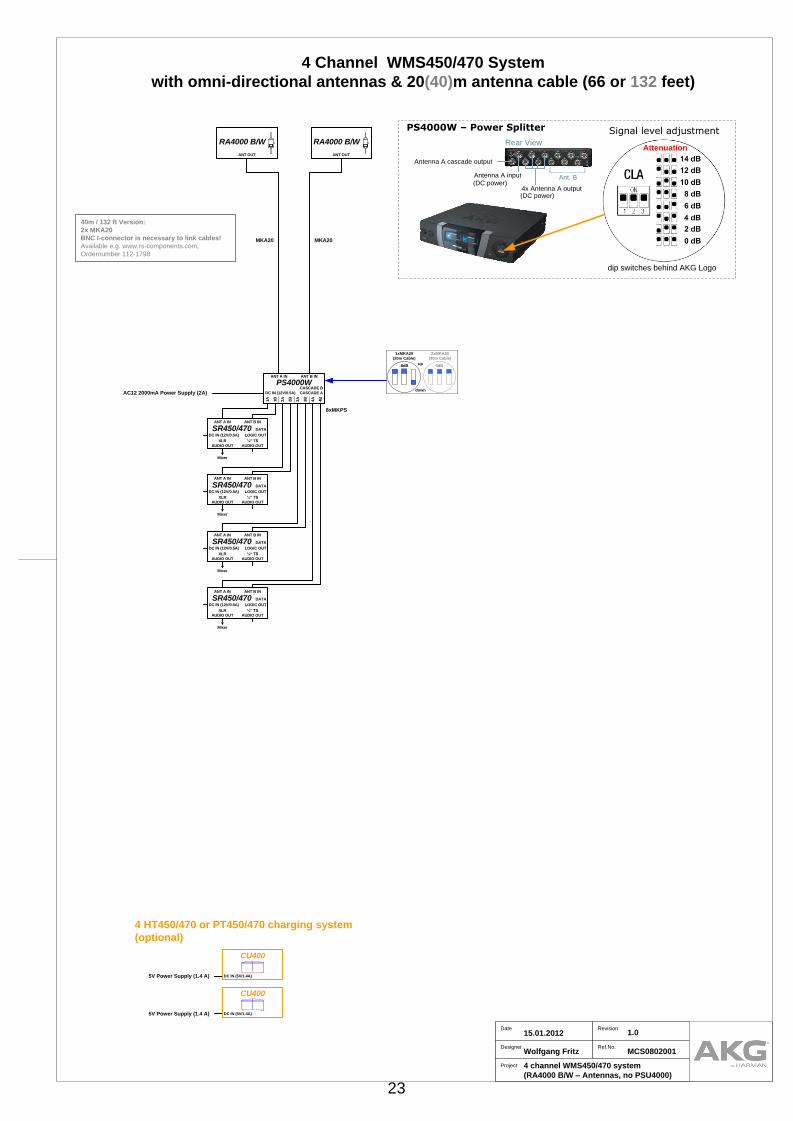
4 Channel WMS450/470 System
with omni-directional antennas & 20(40)m antenna cable (66 or 132 feet)
40m / 132 ft Version:
2x MKA20
BNC I-connector is necessary to link cables!
Available e.g. www.rs-components.com,
Ordernumber 112-1798
Rear View
4x Antenna A output (DC power)
Antenna A input Ant. B
Antenna A cascade output
(DC power)
dip switches behind AKG Logo
Signal level adjustment
Attenuation
PS4000W – Power Splitter
1A
1B
2A
2B
3A
3B
4B
4A
ANT A IN ANT B IN
DC IN (12V/0.5A)
PS4000WCASCADE A
CASCADE B
RA4000 B/W
ANT OUT
RA4000 B/W
ANT OUT
2xMKA20
(40m Cable)
1xMKA20
(20m Cable)
-8dBup
down
0dB
AC12 2000mA Power Supply (2A)
SR450/470
XLR
AUDIO OUT
ANT A IN
DC IN (12V/0.5A)
¼“ TS
AUDIO OUT
ANT B IN
▼
Mixer
DATA
LOGIC OUT
SR450/470
XLR
AUDIO OUT
ANT A IN
DC IN (12V/0.5A)
¼“ TS
AUDIO OUT
ANT B IN
▼
Mixer
DATA
LOGIC OUT
SR450/470
XLR
AUDIO OUT
ANT A IN
DC IN (12V/0.5A)
¼“ TS
AUDIO OUT
ANT B IN
▼
Mixer
DATA
LOGIC OUT
SR450/470
XLR
AUDIO OUT
ANT A IN
DC IN (12V/0.5A)
¼“ TS
AUDIO OUT
ANT B IN
▼
Mixer
DATA
LOGIC OUT
5V Power Supply (1.4 A)
CU400
DC IN (5V/1.4A)
5V Power Supply (1.4 A)
CU400
DC IN (5V/1.4A)
23

units description comment4 18 Half-rack receiver with AC-Adapter; hand transmitter with D5 or C5 capsule, or pocket transmitter
with MKGL, or C544L or C555 L+ CK99 L, 2 UHF antennas; RMU 4000 rack mount kit, 1 AA
size battery, 1 stand adapter
1 59 Wide band antenna multi coupler (4+1 out) without AC-Adapter
2 66 External omni-directional active dipoleantenna with amplifier (2 req.)
8 54 Connecting cable for PS to SR 2.15ft (65cm)
2 55 66 ft. (20m) Cables for connecting ext. antennas to multi-couplers (2 req.) KOAX RG58
1 8 12V AC-Adapter (EU-Version) power supply CU4000, PS4000 W (you can also use a PSU4000
output)
2 55 66 ft. (20m) Cables for connecting ext. antennas to multi-couplers (2 req.) KOAX RG58
2 BNC I-connector EXTERNAL !! Not available at AKG - BNC I-Connector
(you can buy it at www.rs-components.com, Ordernumber 112-1798)
units description comment2 35 Charging unit for WMS 400 transmitters, AC adapters included
4 Channel WMS450/470 System with omni-directional antennas, no PSU4000
Optional Components
Additional parts for 40m(132feet) Antenna Cable
CU 400 EU/US/UK
RA4000 B/W
PS4000 W
MK PS
MKA 20
AC12 2000mA EU/US/UK
MKA 20
WMS450/470 Set
WM
S4
50
/47
00
1 / 2
01
2
24

6 HT450/470 or PT450/470 charging system
(optional)
Project
Designer
Date Revision
5 channel WMS450/470 system
(SRA2 B/W – Antennas)
Wolfgang Fritz
15.01.2012 1.0
Ref.No.MCS0802001
MKA20 MKA20
5 Channel WMS450/470 System
with directional antennas & 20(40)m antenna cable (66 or 132 feet)
40m / 132 ft Version:
2x MKA20
BNC I-connector is necessary to link cables!
Available e.g. www.rs-components.com,
Ordernumber 112-1798
Rear View
4x Antenna A output (DC power)
Antenna A input Ant. B
Antenna A cascade output
(DC power)
dip switches behind AKG Logo
Signal level adjustment
Attenuation
PS4000W – Power SplitterSRA2 B/W
ANT OUT
SRA2 B/W
ANT OUT
1A
1B
2A
2B
3A
3B
4B
4A
ANT A IN ANT B IN
DC IN (12V/0.5A)
PS4000WCASCADE A
CASCADE B
10xMKPS
2xMKA20
(40m Cable)
1xMKA20
(20m Cable)
-12dBup
down
-2dB
SR450/470
XLR
AUDIO OUT
ANT A IN
DC IN (12V/0.5A)
¼“ TS
AUDIO OUT
ANT B IN
▼
Mixer
DATA
LOGIC OUT
SR450/470
XLR
AUDIO OUT
ANT A IN
DC IN (12V/0.5A)
¼“ TS
AUDIO OUT
ANT B IN
▼
Mixer
DATA
LOGIC OUT
SR450/470
XLR
AUDIO OUT
ANT A IN
DC IN (12V/0.5A)
¼“ TS
AUDIO OUT
ANT B IN
▼
Mixer
DATA
LOGIC OUT
SR450/470
XLR
AUDIO OUT
ANT A IN
DC IN (12V/0.5A)
¼“ TS
AUDIO OUT
ANT B IN
▼
Mixer
DATA
LOGIC OUT
SR450/470
XLR
AUDIO OUT
ANT A IN
DC IN (12V/0.5A)
¼“ TS
AUDIO OUT
ANT B IN
▼
Mixer
DATA
LOGIC OUT
AC12 2000mA Power Supply (2A)
AC12 Power Supply (500mA)
5V Power Supply (1.4 A)
CU400
DC IN (5V/1.4A)
5V Power Supply (1.4 A)
CU400
DC IN (5V/1.4A)
5V Power Supply (1.4 A)
CU400
DC IN (5V/1.4A)
25

units description comment5 18 Half-rack receiver with AC-Adapter; hand transmitter with D5 or C5 capsule, or pocket transmitter
with MKGL, or C544L or C555 L+ CK99 L, 2 UHF antennas; RMU 4000 rack mount kit, 1 AA
size battery, 1 stand adapter
1 59 Wide band antenna multi coupler (4+1 out) without AC-Adapter
2 72 External directional active "paddle" antenna with amplifier (2 req.)
10 54 Connecting cable for PS to SR 2.15ft (65cm)
2 55 66 ft. (20m) Cables for connecting ext. antennas to multi-couplers (2 req.) KOAX RG58
1 8 12V AC-Adapter (EU-Version) power supply CU4000, PS4000 W (you can also use a PSU4000
output)
1 4 12V AC-Adapter for 1 ASU4000, AB4000, HUB4000Q or SR4500.
2 55 66 ft. (20m) Cables for connecting ext. antennas to multi-couplers (2 req.) KOAX RG58
2 BNC I-connector EXTERNAL !! Not available at AKG - BNC I-Connector
(you can buy it at www.rs-components.com, Ordernumber 112-1798)
units description comment3 35 Charging unit for WMS 400 transmitters, AC adapters included
5 Channel WMS450/470 System with directional antennas
Optional Components
Additional parts for 40m(132feet) Antenna Cable
CU 400 EU/US/UK
SRA 2 B/W
PS4000 W
MK PS
MKA 20
AC12 2000mA EU/US/UK
MKA 20
WMS450/470 Set
AC12 500mA EU/US/UK
WM
S4
50
/47
00
1 / 2
01
2
26

6 HT450/470 or PT450/470 charging system
(optional)
Project
Designer
Date Revision
5 channel WMS450/470 system
(RA4000 B/W – Antennas)
Wolfgang Fritz
15.01.2012 1.0
Ref.No.MCS0802001
MKA20 MKA20
5 Channel WMS450/470 System
with omni-directional antennas & 20(40)m antenna cable (66 or 132 feet)
40m / 132 ft Version:
2x MKA20
BNC I-connector is necessary to link cables!
Available e.g. www.rs-components.com,
Ordernumber 112-1798
Rear View
4x Antenna A output (DC power)
Antenna A input Ant. B
Antenna A cascade output
(DC power)
dip switches behind AKG Logo
Signal level adjustment
Attenuation
PS4000W – Power Splitter
1A
1B
2A
2B
3A
3B
4B
4A
ANT A IN ANT B IN
DC IN (12V/0.5A)
PS4000WCASCADE A
CASCADE B
10xMKPS
2xMKA20
(40m Cable)
1xMKA20
(20m Cable)
-8dBup
down
0dB
RA4000 B/W
ANT OUT
RA4000 B/W
ANT OUT
SR450/470
XLR
AUDIO OUT
ANT A IN
DC IN (12V/0.5A)
¼“ TS
AUDIO OUT
ANT B IN
▼
Mixer
DATA
LOGIC OUT
SR450/470
XLR
AUDIO OUT
ANT A IN
DC IN (12V/0.5A)
¼“ TS
AUDIO OUT
ANT B IN
▼
Mixer
DATA
LOGIC OUT
SR450/470
XLR
AUDIO OUT
ANT A IN
DC IN (12V/0.5A)
¼“ TS
AUDIO OUT
ANT B IN
▼
Mixer
DATA
LOGIC OUT
SR450/470
XLR
AUDIO OUT
ANT A IN
DC IN (12V/0.5A)
¼“ TS
AUDIO OUT
ANT B IN
▼
Mixer
DATA
LOGIC OUT
SR450/470
XLR
AUDIO OUT
ANT A IN
DC IN (12V/0.5A)
¼“ TS
AUDIO OUT
ANT B IN
▼
Mixer
DATA
LOGIC OUT
AC12 2000mA Power Supply (2A)
AC12 Power Supply (500mA)
5V Power Supply (1.4 A)
CU400
DC IN (5V/1.4A)
5V Power Supply (1.4 A)
CU400
DC IN (5V/1.4A)
5V Power Supply (1.4 A)
CU400
DC IN (5V/1.4A)
27
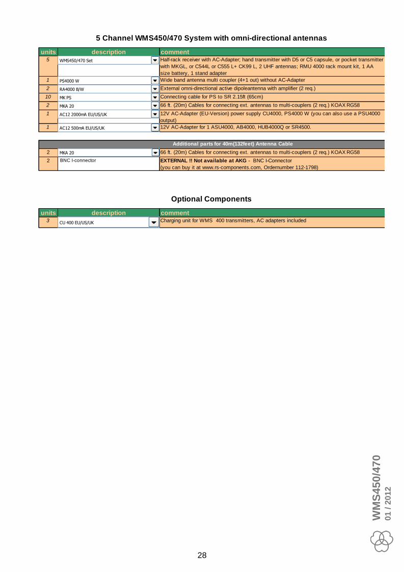
units description comment5 18 Half-rack receiver with AC-Adapter; hand transmitter with D5 or C5 capsule, or pocket transmitter
with MKGL, or C544L or C555 L+ CK99 L, 2 UHF antennas; RMU 4000 rack mount kit, 1 AA
size battery, 1 stand adapter
1 59 Wide band antenna multi coupler (4+1 out) without AC-Adapter
2 66 External omni-directional active dipoleantenna with amplifier (2 req.)
10 54 Connecting cable for PS to SR 2.15ft (65cm)
2 55 66 ft. (20m) Cables for connecting ext. antennas to multi-couplers (2 req.) KOAX RG58
1 8 12V AC-Adapter (EU-Version) power supply CU4000, PS4000 W (you can also use a PSU4000
output)
1 4 12V AC-Adapter for 1 ASU4000, AB4000, HUB4000Q or SR4500.
2 55 66 ft. (20m) Cables for connecting ext. antennas to multi-couplers (2 req.) KOAX RG58
2 BNC I-connector EXTERNAL !! Not available at AKG - BNC I-Connector
(you can buy it at www.rs-components.com, Ordernumber 112-1798)
units description comment3 35 Charging unit for WMS 400 transmitters, AC adapters included
5 Channel WMS450/470 System with omni-directional antennas
Optional Components
Additional parts for 40m(132feet) Antenna Cable
CU 400 EU/US/UK
RA4000 B/W
PS4000 W
MK PS
MKA 20
AC12 2000mA EU/US/UK
MKA 20
WMS450/470 Set
AC12 500mA EU/US/UK
WM
S4
50
/47
00
1 / 2
01
2
28
6 HT450/470 or PT450/470 charging system
(optional)
Project
Designer
Date Revision
6 channel WMS450/470 system
(SRA2 B/W – Antennas)
Wolfgang Fritz
15.01.2012 1.0
Ref.No.MCS0802001
MKA20 MKA20
6 Channel WMS450/470 System
with directional antennas & 20(40)m antenna cable (66 or 132 feet)
40m / 132 ft Version:
2x MKA20
BNC I-connector is necessary to link cables!
Available e.g. www.rs-components.com,
Ordernumber 112-1798
Rear View
4x Antenna A output (DC power)
Antenna A input Ant. B
Antenna A cascade output
(DC power)
dip switches behind AKG Logo
Signal level adjustment
Attenuation
PS4000W – Power SplitterSRA2 B/W
ANT OUT
SRA2 B/W
ANT OUT
1A
1B
2A
2B
3A
3B
4B
4A
ANT A IN ANT B IN
DC IN (12V/0.5A)
PS4000WCASCADE A
CASCADE B
1A
1B
2A
2B
3A
3B
4B
4A
ANT A IN ANT B IN
DC IN (12V/0.5A)
PS4000WCASCADE A
CASCADE B
0dBup
down
8xMKPS 8xMKPS
2xMKA20
(40m Cable)
1xMKA20
(20m Cable)
-12dBup
down
-2dB2xMKPS
SR450/470
XLR
AUDIO OUT
ANT A IN
DC IN (12V/0.5A)
¼“ TS
AUDIO OUT
ANT B IN
▼
Mixer
DATA
LOGIC OUT
SR450/470
XLR
AUDIO OUT
ANT A IN
DC IN (12V/0.5A)
¼“ TS
AUDIO OUT
ANT B IN
▼
Mixer
DATA
LOGIC OUT
SR450/470
XLR
AUDIO OUT
ANT A IN
DC IN (12V/0.5A)
¼“ TS
AUDIO OUT
ANT B IN
▼
Mixer
DATA
LOGIC OUT
SR450/470
XLR
AUDIO OUT
ANT A IN
DC IN (12V/0.5A)
¼“ TS
AUDIO OUT
ANT B IN
▼
Mixer
DATA
LOGIC OUT
SR450/470
XLR
AUDIO OUT
ANT A IN
DC IN (12V/0.5A)
¼“ TS
AUDIO OUT
ANT B IN
▼
Mixer
DATA
LOGIC OUT
SR450/470
XLR
AUDIO OUT
ANT A IN
DC IN (12V/0.5A)
¼“ TS
AUDIO OUT
ANT B IN
▼
Mixer
DATA
LOGIC OUT
AC12 2000mA Power Supply (2A)
AC12 2000mA Power Supply (2A)
5V Power Supply (1.4 A)
CU400
DC IN (5V/1.4A)
5V Power Supply (1.4 A)
CU400
DC IN (5V/1.4A)
5V Power Supply (1.4 A)
CU400
DC IN (5V/1.4A)
29

units description comment6 18 Half-rack receiver with AC-Adapter; hand transmitter with D5 or C5 capsule, or pocket transmitter
with MKGL, or C544L or C555 L+ CK99 L, 2 UHF antennas; RMU 4000 rack mount kit, 1 AA
size battery, 1 stand adapter
2 59 Wide band antenna multi coupler (4+1 out) without AC-Adapter
2 72 External directional active "paddle" antenna with amplifier (2 req.)
14 54 Connecting cable for PS to SR 2.15ft (65cm)
2 55 66 ft. (20m) Cables for connecting ext. antennas to multi-couplers (2 req.) KOAX RG58
2 8 12V AC-Adapter (EU-Version) power supply CU4000, PS4000 W (you can also use a PSU4000
output)
2 55 66 ft. (20m) Cables for connecting ext. antennas to multi-couplers (2 req.) KOAX RG58
2 BNC I-connector EXTERNAL !! Not available at AKG - BNC I-Connector
(you can buy it at www.rs-components.com, Ordernumber 112-1798)
units description comment3 35 Charging unit for WMS 400 transmitters, AC adapters included
6 Channel WMS450/470 System with directional antennas
Optional Components
Additional parts for 40m(132feet) Antenna Cable
CU 400 EU/US/UK
SRA 2 B/W
PS4000 W
MK PS
MKA 20
AC12 2000mA EU/US/UK
MKA 20
WMS450/470 Set
WM
S4
50
/47
00
1 / 2
01
2
30

6 HT450/470 or PT450/470 charging system
(optional)
Project
Designer
Date Revision
6 channel WMS450/470 system
(RA4000 B/W – Antennas)
Wolfgang Fritz
15.01.2012 1.0
Ref.No.MCS0802001
MKA20 MKA20
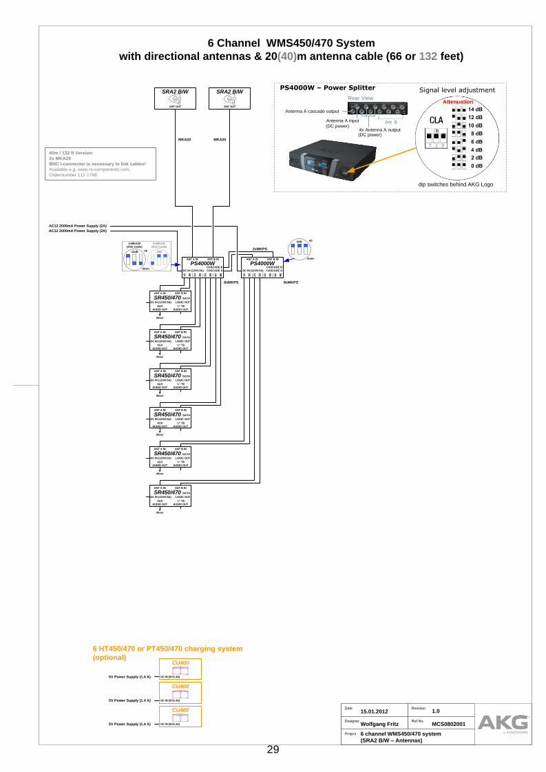
6 Channel WMS450/470 System
with omni-directional antennas & 20(40)m antenna cable (66 or 132 feet)
40m / 132 ft Version:
2x MKA20
BNC I-connector is necessary to link cables!
Available e.g. www.rs-components.com,
Ordernumber 112-1798
Rear View
4x Antenna A output (DC power)
Antenna A input Ant. B
Antenna A cascade output
(DC power)
dip switches behind AKG Logo
Signal level adjustment
Attenuation
PS4000W – Power Splitter
1A
1B
2A
2B
3A
3B
4B
4A
ANT A IN ANT B IN
DC IN (12V/0.5A)
PS4000WCASCADE A
CASCADE B
1A
1B
2A
2B
3A
3B
4B
4A
ANT A IN ANT B IN
DC IN (12V/0.5A)
PS4000WCASCADE A
CASCADE B
0dBup
down
8xMKPS 8xMKPS
2xMKA20
(40m Cable)
1xMKA20
(20m Cable)
-8dBup
down
0dB
RA4000 B/W
ANT OUT
RA4000 B/W
ANT OUT
2xMKPS
SR450/470
XLR
AUDIO OUT
ANT A IN
DC IN (12V/0.5A)
¼“ TS
AUDIO OUT
ANT B IN
▼
Mixer
DATA
LOGIC OUT
SR450/470
XLR
AUDIO OUT
ANT A IN
DC IN (12V/0.5A)
¼“ TS
AUDIO OUT
ANT B IN
▼
Mixer
DATA
LOGIC OUT
SR450/470
XLR
AUDIO OUT
ANT A IN
DC IN (12V/0.5A)
¼“ TS
AUDIO OUT
ANT B IN
▼
Mixer
DATA
LOGIC OUT
SR450/470
XLR
AUDIO OUT
ANT A IN
DC IN (12V/0.5A)
¼“ TS
AUDIO OUT
ANT B IN
▼
Mixer
DATA
LOGIC OUT
SR450/470
XLR
AUDIO OUT
ANT A IN
DC IN (12V/0.5A)
¼“ TS
AUDIO OUT
ANT B IN
▼
Mixer
DATA
LOGIC OUT
SR450/470
XLR
AUDIO OUT
ANT A IN
DC IN (12V/0.5A)
¼“ TS
AUDIO OUT
ANT B IN
▼
Mixer
DATA
LOGIC OUT
AC12 2000mA Power Supply (2A)
AC12 2000mA Power Supply (2A)
5V Power Supply (1.4 A)
CU400
DC IN (5V/1.4A)
5V Power Supply (1.4 A)
CU400
DC IN (5V/1.4A)
5V Power Supply (1.4 A)
CU400
DC IN (5V/1.4A)
31
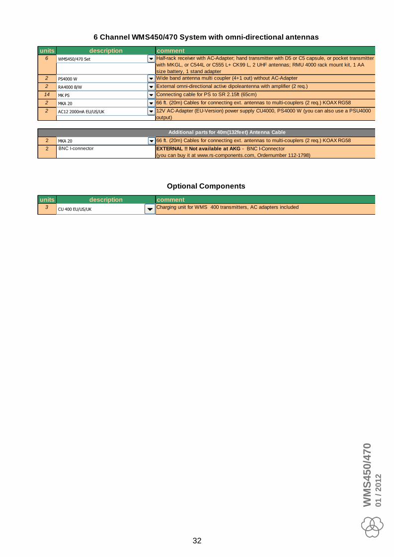
units description comment6 18 Half-rack receiver with AC-Adapter; hand transmitter with D5 or C5 capsule, or pocket transmitter
with MKGL, or C544L or C555 L+ CK99 L, 2 UHF antennas; RMU 4000 rack mount kit, 1 AA
size battery, 1 stand adapter
2 59 Wide band antenna multi coupler (4+1 out) without AC-Adapter
2 66 External omni-directional active dipoleantenna with amplifier (2 req.)
14 54 Connecting cable for PS to SR 2.15ft (65cm)
2 55 66 ft. (20m) Cables for connecting ext. antennas to multi-couplers (2 req.) KOAX RG58
2 8 12V AC-Adapter (EU-Version) power supply CU4000, PS4000 W (you can also use a PSU4000
output)
2 55 66 ft. (20m) Cables for connecting ext. antennas to multi-couplers (2 req.) KOAX RG58
2 BNC I-connector EXTERNAL !! Not available at AKG - BNC I-Connector
(you can buy it at www.rs-components.com, Ordernumber 112-1798)
units description comment3 35 Charging unit for WMS 400 transmitters, AC adapters included
6 Channel WMS450/470 System with omni-directional antennas
Optional Components
Additional parts for 40m(132feet) Antenna Cable
CU 400 EU/US/UK
RA4000 B/W
PS4000 W
MK PS
MKA 20
AC12 2000mA EU/US/UK
MKA 20
WMS450/470 Set
WM
S4
50
/47
00
1 / 2
01
2
32

8 HT450/470 or PT450/470 charging system
(optional)
Project
Designer
Date Revision
8 channel WMS450/470 system
(SRA2 B/W – Antennas)
Wolfgang Fritz
15.01.2012 1.0
Ref.No.MCS0802001
MKA20 MKA20
8 Channel WMS450/470 System
with directional antennas & 20(40)m antenna cable (66 or 132 feet)
40m / 132 ft Version:
2x MKA20
BNC I-connector is necessary to link cables!
Available e.g. www.rs-components.com,
Ordernumber 112-1798
Rear View
4x Antenna A output (DC power)
Antenna A input Ant. B
Antenna A cascade output
(DC power)
dip switches behind AKG Logo
Signal level adjustment
Attenuation
PS4000W – Power SplitterSRA2 B/W
ANT OUT
SRA2 B/W
ANT OUT
1A
1B
2A
2B
3A
3B
4B
4A
ANT A IN ANT B IN
DC IN (12V/0.5A)
PS4000WCASCADE A
CASCADE B
1A
1B
2A
2B
3A
3B
4B
4A
ANT A IN ANT B IN
DC IN (12V/0.5A)
PS4000WCASCADE A
CASCADE B
0dBup
down
8xMKPS 8xMKPS
2xMKA20
(40m Cable)
1xMKA20
(20m Cable)
-12dBup
down
-2dB2xMKPS
SR450/470
XLR
AUDIO OUT
ANT A IN
DC IN (12V/0.5A)
¼“ TS
AUDIO OUT
ANT B IN
▼
Mixer
DATA
LOGIC OUT
SR450/470
XLR
AUDIO OUT
ANT A IN
DC IN (12V/0.5A)
¼“ TS
AUDIO OUT
ANT B IN
▼
Mixer
DATA
LOGIC OUT
SR450/470
XLR
AUDIO OUT
ANT A IN
DC IN (12V/0.5A)
¼“ TS
AUDIO OUT
ANT B IN
▼
Mixer
DATA
LOGIC OUT
SR450/470
XLR
AUDIO OUT
ANT A IN
DC IN (12V/0.5A)
¼“ TS
AUDIO OUT
ANT B IN
▼
Mixer
DATA
LOGIC OUT
SR450/470
XLR
AUDIO OUT
ANT A IN
DC IN (12V/0.5A)
¼“ TS
AUDIO OUT
ANT B IN
▼
Mixer
DATA
LOGIC OUT
SR450/470
XLR
AUDIO OUT
ANT A IN
DC IN (12V/0.5A)
¼“ TS
AUDIO OUT
ANT B IN
▼
Mixer
DATA
LOGIC OUT
SR450/470
XLR
AUDIO OUT
ANT A IN
DC IN (12V/0.5A)
¼“ TS
AUDIO OUT
ANT B IN
▼
Mixer
DATA
LOGIC OUT
SR450/470
XLR
AUDIO OUT
ANT A IN
DC IN (12V/0.5A)
¼“ TS
AUDIO OUT
ANT B IN
▼
Mixer
DATA
LOGIC OUT
AC12 2000mA Power Supply (2A)
AC12 2000mA Power Supply (2A)
5V Power Supply (1.4 A)
CU400
DC IN (5V/1.4A)
5V Power Supply (1.4 A)
CU400
DC IN (5V/1.4A)
5V Power Supply (1.4 A)
CU400
DC IN (5V/1.4A)
5V Power Supply (1.4 A)
CU400
DC IN (5V/1.4A)
33

units description comment8 18 Half-rack receiver with AC-Adapter; hand transmitter with D5 or C5 capsule, or pocket transmitter
with MKGL, or C544L or C555 L+ CK99 L, 2 UHF antennas; RMU 4000 rack mount kit, 1 AA
size battery, 1 stand adapter
2 59 Wide band antenna multi coupler (4+1 out) without AC-Adapter
2 72 External directional active "paddle" antenna with amplifier (2 req.)
18 54 Connecting cable for PS to SR 2.15ft (65cm)
2 55 66 ft. (20m) Cables for connecting ext. antennas to multi-couplers (2 req.) KOAX RG58
2 8 12V AC-Adapter (EU-Version) power supply CU4000, PS4000 W (you can also use a PSU4000
output)
2 55 66 ft. (20m) Cables for connecting ext. antennas to multi-couplers (2 req.) KOAX RG58
2 BNC I-connector EXTERNAL !! Not available at AKG - BNC I-Connector
(you can buy it at www.rs-components.com, Ordernumber 112-1798)
units description comment4 35 Charging unit for WMS 400 transmitters, AC adapters included
8 Channel WMS450/470 System with directional antennas
Optional Components
Additional parts for 40m(132feet) Antenna Cable
CU 400 EU/US/UK
SRA 2 B/W
PS4000 W
MK PS
MKA 20
AC12 2000mA EU/US/UK
MKA 20
WMS450/470 Set
WM
S4
50
/47
00
1 / 2
01
2
34

Project
Designer
Date Revision
8 channel WMS450/470 system
(RA4000 B/W – Antennas)
Wolfgang Fritz
15.01.2012 1.0
Ref.No.MCS0802001
MKA20 MKA20
8 Channel WMS450/470 System
with omni-directional antennas & 20(40)m antenna cable (66 or 132 feet)
40m / 132 ft Version:
2x MKA20
BNC I-connector is necessary to link cables!
Available e.g. www.rs-components.com,
Ordernumber 112-1798
Rear View
4x Antenna A output (DC power)
Antenna A input Ant. B
Antenna A cascade output
(DC power)
dip switches behind AKG Logo
Signal level adjustment
Attenuation
PS4000W – Power Splitter
1A
1B
2A
2B
3A
3B
4B
4A
ANT A IN ANT B IN
DC IN (12V/0.5A)
PS4000WCASCADE A
CASCADE B
1A
1B
2A
2B
3A
3B
4B
4A
ANT A IN ANT B IN
DC IN (12V/0.5A)
PS4000WCASCADE A
CASCADE B
0dBup
down
8xMKPS 8xMKPS
2xMKA20
(40m Cable)
1xMKA20
(20m Cable)
-8dBup
down
0dB
RA4000 B/W
ANT OUT
RA4000 B/W
ANT OUT
2xMKPS
SR450/470
XLR
AUDIO OUT
ANT A IN
DC IN (12V/0.5A)
¼“ TS
AUDIO OUT
ANT B IN
▼
Mixer
DATA
LOGIC OUT
SR450/470
XLR
AUDIO OUT
ANT A IN
DC IN (12V/0.5A)
¼“ TS
AUDIO OUT
ANT B IN
▼
Mixer
DATA
LOGIC OUT
SR450/470
XLR
AUDIO OUT
ANT A IN
DC IN (12V/0.5A)
¼“ TS
AUDIO OUT
ANT B IN
▼
Mixer
DATA
LOGIC OUT
SR450/470
XLR
AUDIO OUT
ANT A IN
DC IN (12V/0.5A)
¼“ TS
AUDIO OUT
ANT B IN
▼
Mixer
DATA
LOGIC OUT
SR450/470
XLR
AUDIO OUT
ANT A IN
DC IN (12V/0.5A)
¼“ TS
AUDIO OUT
ANT B IN
▼
Mixer
DATA
LOGIC OUT
SR450/470
XLR
AUDIO OUT
ANT A IN
DC IN (12V/0.5A)
¼“ TS
AUDIO OUT
ANT B IN
▼
Mixer
DATA
LOGIC OUT
AC12 2000mA Power Supply (2A)
AC12 2000mA Power Supply (2A)
SR450/470
XLR
AUDIO OUT
ANT A IN
DC IN (12V/0.5A)
¼“ TS
AUDIO OUT
ANT B IN
▼
Mixer
DATA
LOGIC OUT
SR450/470
XLR
AUDIO OUT
ANT A IN
DC IN (12V/0.5A)
¼“ TS
AUDIO OUT
ANT B IN
▼
Mixer
DATA
LOGIC OUT
5V Power Supply (1.4 A)
CU400
DC IN (5V/1.4A)
5V Power Supply (1.4 A)
CU400
DC IN (5V/1.4A)
5V Power Supply (1.4 A)
CU400
DC IN (5V/1.4A)
5V Power Supply (1.4 A)
CU400
DC IN (5V/1.4A)
8 HT450/470 or PT450/470 charging system
(optional)
35

units description comment code8 18 Half-rack receiver with AC-Adapter; hand transmitter with D5 or C5 capsule, or pocket transmitter
with MKGL, or C544L or C555 L+ CK99 L, 2 UHF antennas; RMU 4000 rack mount kit, 1 AA
size battery, 1 stand adapter
0
2 59 Wide band antenna multi coupler (4+1 out) without AC-Adapter 2996Z0008
2 66 External omni-directional active dipoleantenna with amplifier (2 req.) 2632Z0030
18 54 Connecting cable for PS to SR 2.15ft (65cm) 6000H0206
2 55 66 ft. (20m) Cables for connecting ext. antennas to multi-couplers (2 req.) KOAX RG58 6000H0205
2 8 12V AC-Adapter (EU-Version) power supply CU4000, PS4000 W (you can also use a PSU4000
output)
7801H000…
2 55 66 ft. (20m) Cables for connecting ext. antennas to multi-couplers (2 req.) KOAX RG58 6000H0205
2 BNC I-connector EXTERNAL !! Not available at AKG - BNC I-Connector
(you can buy it at www.rs-components.com, Ordernumber 112-1798)
units description comment code4 35 Charging unit for WMS 400 transmitters, AC adapters included 2934Z000…
8 Channel WMS450/470 System with omni-directional antennas
Optional Components
Additional parts for 40m(132feet) Antenna Cable
CU 400 EU/US/UK
RA4000 B/W
PS4000 W
MK PS
MKA 20
AC12 2000mA EU/US/UK
MKA 20
WMS450/470 Set
WM
S4
50
/47
00
1 / 2
01
2
36

10 HT450/470 or PT450/470 charging system
(optional)
Project
Designer
Date Revision
9 channel WMS450/470 system
(SRA2 B/W – Antennas)
Wolfgang Fritz
15.01.2012 1.0
Ref.No.MCS0802001
MKA20 MKA20
9 Channel WMS450/470 System
with directional antennas & 20(40)m antenna cable (66 or 132 feet)
40m / 132 ft Version:
2x MKA20
BNC I-connector is necessary to link cables!
Available e.g. www.rs-components.com,
Ordernumber 112-1798
Rear View
4x Antenna A output (DC power)
Antenna A input Ant. B
Antenna A cascade output
(DC power)
dip switches behind AKG Logo
Signal level adjustment
Attenuation
PS4000W – Power SplitterSRA2 B/W
ANT OUT
SRA2 B/W
ANT OUT
1A
1B
2A
2B
3A
3B
4B
4A
ANT A IN ANT B IN
DC IN (12V/0.5A)
PS4000WCASCADE A
CASCADE B
1A
1B
2A
2B
3A
3B
4B
4A
ANT A IN ANT B IN
DC IN (12V/0.5A)
PS4000WCASCADE A
CASCADE B
0dBup
down
8xMKPS 8xMKPS
2xMKA20
(40m Cable)
1xMKA20
(20m Cable)
-12dBup
down
-2dB2xMKPS
2xMKPS
SR450/470
XLR
AUDIO OUT
ANT A IN
DC IN (12V/0.5A)
¼“ TS
AUDIO OUT
ANT B IN
▼
Mixer
DATA
LOGIC OUT
SR450/470
XLR
AUDIO OUT
ANT A IN
DC IN (12V/0.5A)
¼“ TS
AUDIO OUT
ANT B IN
▼
Mixer
DATA
LOGIC OUT
SR450/470
XLR
AUDIO OUT
ANT A IN
DC IN (12V/0.5A)
¼“ TS
AUDIO OUT
ANT B IN
▼
Mixer
DATA
LOGIC OUT
SR450/470
XLR
AUDIO OUT
ANT A IN
DC IN (12V/0.5A)
¼“ TS
AUDIO OUT
ANT B IN
▼
Mixer
DATA
LOGIC OUT
SR450/470
XLR
AUDIO OUT
ANT A IN
DC IN (12V/0.5A)
¼“ TS
AUDIO OUT
ANT B IN
▼
Mixer
DATA
LOGIC OUT
SR450/470
XLR
AUDIO OUT
ANT A IN
DC IN (12V/0.5A)
¼“ TS
AUDIO OUT
ANT B IN
▼
Mixer
DATA
LOGIC OUT
SR450/470
XLR
AUDIO OUT
ANT A IN
DC IN (12V/0.5A)
¼“ TS
AUDIO OUT
ANT B IN
▼
Mixer
DATA
LOGIC OUT
SR450/470
XLR
AUDIO OUT
ANT A IN
DC IN (12V/0.5A)
¼“ TS
AUDIO OUT
ANT B IN
▼
Mixer
DATA
LOGIC OUTAC12 Power Supply (500mA)
AC12 2000mA Power Supply (2A)
AC12 2000mA Power Supply (2A)
SR450/470
XLR
AUDIO OUT
ANT A IN
DC IN (12V/0.5A)
¼“ TS
AUDIO OUT
ANT B IN
▼
Mixer
DATA
LOGIC OUT
5V Power Supply (1.4 A)
CU400
DC IN (5V/1.4A)
5V Power Supply (1.4 A)
CU400
DC IN (5V/1.4A)
5V Power Supply (1.4 A)
CU400
DC IN (5V/1.4A) 5V Power Supply (1.4 A)
CU400
DC IN (5V/1.4A)
5V Power Supply (1.4 A)
CU400
DC IN (5V/1.4A)
37

units description comment9 18 Half-rack receiver with AC-Adapter; hand transmitter with D5 or C5 capsule, or pocket transmitter
with MKGL, or C544L or C555 L+ CK99 L, 2 UHF antennas; RMU 4000 rack mount kit, 1 AA
size battery, 1 stand adapter
2 59 Wide band antenna multi coupler (4+1 out) without AC-Adapter
2 72 External directional active "paddle" antenna with amplifier (2 req.)
20 54 Connecting cable for PS to SR 2.15ft (65cm)
2 55 66 ft. (20m) Cables for connecting ext. antennas to multi-couplers (2 req.) KOAX RG58
2 8 12V AC-Adapter (EU-Version) power supply CU4000, PS4000 W (you can also use a PSU4000
output)
1 4 12V AC-Adapter for 1 ASU4000, AB4000, HUB4000Q or SR4500.
2 55 66 ft. (20m) Cables for connecting ext. antennas to multi-couplers (2 req.) KOAX RG58
2 BNC I-connector EXTERNAL !! Not available at AKG - BNC I-Connector
(you can buy it at www.rs-components.com, Ordernumber 112-1798)
units description comment5 35 Charging unit for WMS 400 transmitters, AC adapters included
9 Channel WMS450/470 System with directional antennas
Optional Components
Additional parts for 40m(132feet) Antenna Cable
CU 400 EU/US/UK
SRA 2 B/W
PS4000 W
MK PS
MKA 20
AC12 2000mA EU/US/UK
MKA 20
WMS450/470 Set
AC12 500mA EU/US/UK
WM
S4
50
/47
00
1 / 2
01
2
38

10 HT450/470 or PT450/470 charging system
(optional)
Project
Designer
Date Revision
9 channel WMS450/470 system
(RA4000 B/W – Antennas)
Wolfgang Fritz
15.01.2012 1.0
Ref.No.MCS0802001
MKA20 MKA20
9 Channel WMS450/470 System
with omni-directional antennas & 20(40)m antenna cable (66 or 132 feet)
40m / 132 ft Version:
2x MKA20
BNC I-connector is necessary to link cables!
Available e.g. www.rs-components.com,
Ordernumber 112-1798
Rear View
4x Antenna A output (DC power)
Antenna A input Ant. B
Antenna A cascade output
(DC power)
dip switches behind AKG Logo
Signal level adjustment
Attenuation
PS4000W – Power Splitter
1A
1B
2A
2B
3A
3B
4B
4A
ANT A IN ANT B IN
DC IN (12V/0.5A)
PS4000WCASCADE A
CASCADE B
1A
1B
2A
2B
3A
3B
4B
4A
ANT A IN ANT B IN
DC IN (12V/0.5A)
PS4000WCASCADE A
CASCADE B
AC12 Power Supply (500mA)
0dBup
down
8xMKPS 8xMKPS
2xMKA20
(40m Cable)
1xMKA20
(20m Cable)
-8dBup
down
0dB
RA4000 B/W
ANT OUT
RA4000 B/W
ANT OUT
2xMKPS
2xMKPS
XLR
AUDIO OUT
ANT A IN
DC IN (12V/0.5A)
¼“ TS
AUDIO OUT
ANT B IN
▼
Mixer
DATA
LOGIC OUT
SR450/470
XLR
AUDIO OUT
ANT A IN
DC IN (12V/0.5A)
¼“ TS
AUDIO OUT
ANT B IN
▼
Mixer
DATA
LOGIC OUT
SR450/470
XLR
AUDIO OUT
ANT A IN
DC IN (12V/0.5A)
¼“ TS
AUDIO OUT
ANT B IN
▼
Mixer
DATA
LOGIC OUT
SR450/470
XLR
AUDIO OUT
ANT A IN
DC IN (12V/0.5A)
¼“ TS
AUDIO OUT
ANT B IN
▼
Mixer
DATA
LOGIC OUT
SR450/470
XLR
AUDIO OUT
ANT A IN
DC IN (12V/0.5A)
¼“ TS
AUDIO OUT
ANT B IN
▼
Mixer
DATA
LOGIC OUT
SR450/470
XLR
AUDIO OUT
ANT A IN
DC IN (12V/0.5A)
¼“ TS
AUDIO OUT
ANT B IN
▼
Mixer
DATA
LOGIC OUT
SR450/470
XLR
AUDIO OUT
ANT A IN
DC IN (12V/0.5A)
¼“ TS
AUDIO OUT
ANT B IN
▼
Mixer
DATA
LOGIC OUT
SR450/470
XLR
AUDIO OUT
ANT A IN
DC IN (12V/0.5A)
¼“ TS
AUDIO OUT
ANT B IN
▼
Mixer
DATA
LOGIC OUT
SR450/470
XLR
AUDIO OUT
ANT A IN
DC IN (12V/0.5A)
¼“ TS
AUDIO OUT
ANT B IN
▼
Mixer
DATA
LOGIC OUT
AC12 2000mA Power Supply (2A)
AC12 2000mA Power Supply (2A)
SR450/470
5V Power Supply (1.4 A)
CU400
DC IN (5V/1.4A)
5V Power Supply (1.4 A)
CU400
DC IN (5V/1.4A)
5V Power Supply (1.4 A)
CU400
DC IN (5V/1.4A)
5V Power Supply (1.4 A)
CU400
DC IN (5V/1.4A)
5V Power Supply (1.4 A)
CU400
DC IN (5V/1.4A)
39

units description comment9 18 Half-rack receiver with AC-Adapter; hand transmitter with D5 or C5 capsule, or pocket transmitter
with MKGL, or C544L or C555 L+ CK99 L, 2 UHF antennas; RMU 4000 rack mount kit, 1 AA
size battery, 1 stand adapter
2 59 Wide band antenna multi coupler (4+1 out) without AC-Adapter
2 66 External omni-directional active dipoleantenna with amplifier (2 req.)
20 54 Connecting cable for PS to SR 2.15ft (65cm)
2 55 66 ft. (20m) Cables for connecting ext. antennas to multi-couplers (2 req.) KOAX RG58
2 8 12V AC-Adapter (EU-Version) power supply CU4000, PS4000 W (you can also use a PSU4000
output)
1 4 12V AC-Adapter for 1 ASU4000, AB4000, HUB4000Q or SR4500.
2 55 66 ft. (20m) Cables for connecting ext. antennas to multi-couplers (2 req.) KOAX RG58
2 BNC I-connector EXTERNAL !! Not available at AKG - BNC I-Connector
(you can buy it at www.rs-components.com, Ordernumber 112-1798)
units description comment5 35 Charging unit for WMS 400 transmitters, AC adapters included
9 Channel WMS450/470 System with omni-directional antennas
Optional Components
Additional parts for 40m(132feet) Antenna Cable
CU 400 EU/US/UK
RA4000 B/W
PS4000 W
MK PS
MKA 20
AC12 2000mA EU/US/UK
MKA 20
WMS450/470 Set
AC12 500mA EU/US/UK
WM
S4
50
/47
00
1 / 2
01
2
40
10 HT450/470 or PT450/470 charging system
(optional)
Project
Designer
Date Revision
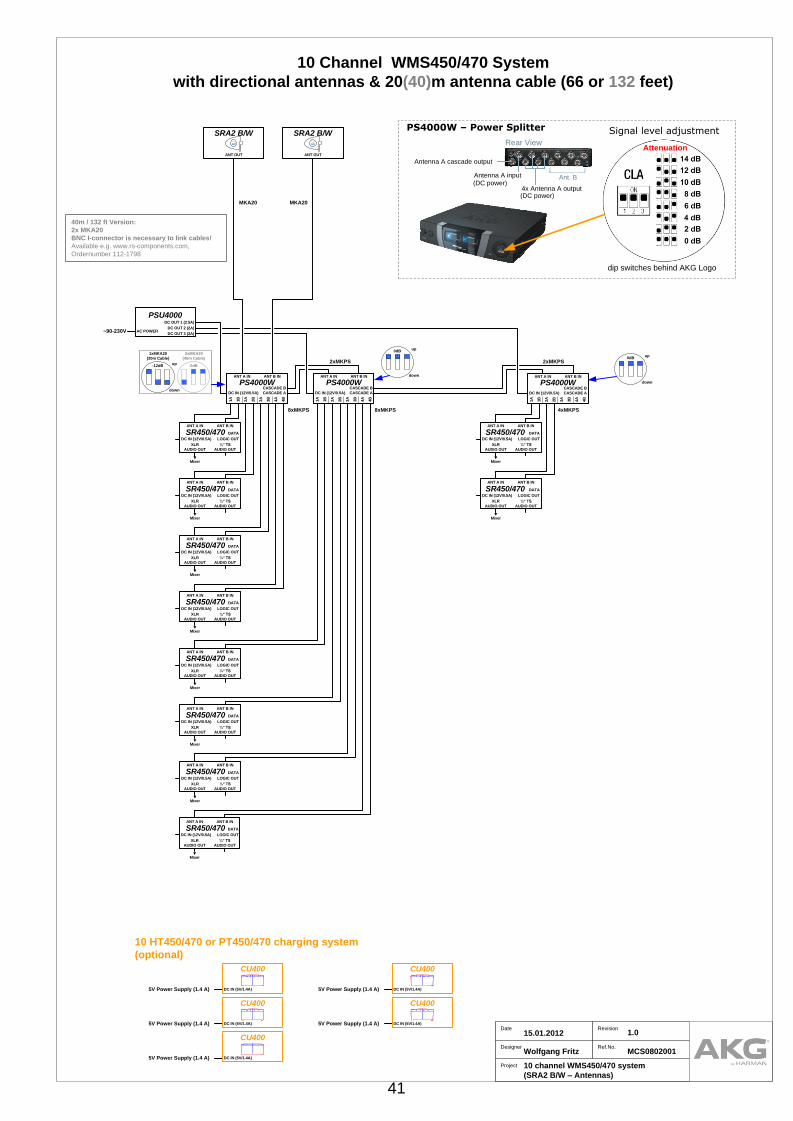
10 channel WMS450/470 system
(SRA2 B/W – Antennas)
Wolfgang Fritz
15.01.2012 1.0
Ref.No.MCS0802001
MKA20 MKA20
10 Channel WMS450/470 System
with directional antennas & 20(40)m antenna cable (66 or 132 feet)
40m / 132 ft Version:
2x MKA20
BNC I-connector is necessary to link cables!
Available e.g. www.rs-components.com,
Ordernumber 112-1798
Rear View
4x Antenna A output (DC power)
Antenna A input Ant. B
Antenna A cascade output
(DC power)
dip switches behind AKG Logo
Signal level adjustment
Attenuation
PS4000W – Power SplitterSRA2 B/W
ANT OUT
SRA2 B/W
ANT OUT
1A
1B
2A
2B
3A
3B
4B
4A
ANT A IN ANT B IN
DC IN (12V/0.5A)
PS4000WCASCADE A
CASCADE B
1A
1B
2A
2B
3A
3B
4B
4A
ANT A IN ANT B IN
DC IN (12V/0.5A)
PS4000WCASCADE A
CASCADE B
1A
1B
2A
2B
3A
3B
4B
4A
ANT A IN ANT B IN
DC IN (12V/0.5A)
PS4000WCASCADE A
CASCADE B
0dBup
down
8xMKPS 8xMKPS 4xMKPS
0dBup
down
2xMKA20
(40m Cable)
1xMKA20
(20m Cable)
-12dBup
down
-2dB
DC OUT 1 (2.5A)
AC POWER
PSU4000
DC OUT 2 (2A)
DC OUT 3 (2A)~90-230V
2xMKPS 2xMKPS
SR450/470
XLR
AUDIO OUT
ANT A IN
DC IN (12V/0.5A)
¼“ TS
AUDIO OUT
ANT B IN
▼
Mixer
DATA
LOGIC OUT
SR450/470
XLR
AUDIO OUT
ANT A IN
DC IN (12V/0.5A)
¼“ TS
AUDIO OUT
ANT B IN
▼
Mixer
DATA
LOGIC OUT
SR450/470
XLR
AUDIO OUT
ANT A IN
DC IN (12V/0.5A)
¼“ TS
AUDIO OUT
ANT B IN
▼
Mixer
DATA
LOGIC OUT
SR450/470
XLR
AUDIO OUT
ANT A IN
DC IN (12V/0.5A)
¼“ TS
AUDIO OUT
ANT B IN
▼
Mixer
DATA
LOGIC OUT
SR450/470
XLR
AUDIO OUT
ANT A IN
DC IN (12V/0.5A)
¼“ TS
AUDIO OUT
ANT B IN
▼
Mixer
DATA
LOGIC OUT
SR450/470
XLR
AUDIO OUT
ANT A IN
DC IN (12V/0.5A)
¼“ TS
AUDIO OUT
ANT B IN
▼
Mixer
DATA
LOGIC OUT
SR450/470
XLR
AUDIO OUT
ANT A IN
DC IN (12V/0.5A)
¼“ TS
AUDIO OUT
ANT B IN
▼
Mixer
DATA
LOGIC OUT
SR450/470
XLR
AUDIO OUT
ANT A IN
DC IN (12V/0.5A)
¼“ TS
AUDIO OUT
ANT B IN
▼
Mixer
DATA
LOGIC OUT
SR450/470
XLR
AUDIO OUT
ANT A IN
DC IN (12V/0.5A)
¼“ TS
AUDIO OUT
ANT B IN
▼
Mixer
DATA
LOGIC OUT
SR450/470
XLR
AUDIO OUT
ANT A IN
DC IN (12V/0.5A)
¼“ TS
AUDIO OUT
ANT B IN
▼
Mixer
DATA
LOGIC OUT
5V Power Supply (1.4 A)
CU400
DC IN (5V/1.4A)
5V Power Supply (1.4 A)
CU400
DC IN (5V/1.4A)
5V Power Supply (1.4 A)
CU400
DC IN (5V/1.4A)
5V Power Supply (1.4 A)
CU400
DC IN (5V/1.4A)
5V Power Supply (1.4 A)
CU400
DC IN (5V/1.4A)
41

units description comment10 18 Half-rack receiver with AC-Adapter; hand transmitter with D5 or C5 capsule, or pocket transmitter
with MKGL, or C544L or C555 L+ CK99 L, 2 UHF antennas; RMU 4000 rack mount kit, 1 AA
size battery, 1 stand adapter
3 59 Wide band antenna multi coupler (4+1 out) without AC-Adapter
2 72 External directional active "paddle" antenna with amplifier (2 req.)
24 54 Connecting cable for PS to SR 2.15ft (65cm)
2 55 66 ft. (20m) Cables for connecting ext. antennas to multi-couplers (2 req.) KOAX RG58
1 60 Central Power supply unit for powering up to three HUB4000Q, CU4000 or up to 12 receivers via
PS4000W, Mains Cable
2 55 66 ft. (20m) Cables for connecting ext. antennas to multi-couplers (2 req.) KOAX RG58
2 BNC I-connector EXTERNAL !! Not available at AKG - BNC I-Connector
(you can buy it at www.rs-components.com, Ordernumber 112-1798)
units description comment5 35 Charging unit for WMS 400 transmitters, AC adapters included
10 Channel WMS450/470 System with directional antennas
Optional Components
Additional parts for 40m(132feet) Antenna Cable
CU 400 EU/US/UK
SRA 2 B/W
PS4000 W
MK PS
MKA 20
PSU4000
MKA 20
WMS450/470 Set
WM
S4
50
/47
00
1 / 2
01
2
42

10 HT450/470 or PT450/470 charging system
(optional)
Project
Designer
Date Revision
10 channel WMS450/470 system
(RA4000 B/W – Antennas)
Wolfgang Fritz
15.01.2012 1.0
Ref.No.MCS0802001
MKA20 MKA20
10 Channel WMS450/470 System
with omni-directional antennas & 20(40)m antenna cable (66 or 132 feet)
40m / 132 ft Version:
2x MKA20
BNC I-connector is necessary to link cables!
Available e.g. www.rs-components.com,
Ordernumber 112-1798
Rear View
4x Antenna A output (DC power)
Antenna A input Ant. B
Antenna A cascade output
(DC power)
dip switches behind AKG Logo
Signal level adjustment
Attenuation
PS4000W – Power Splitter
1A
1B
2A
2B
3A
3B
4B
4A
ANT A IN ANT B IN
DC IN (12V/0.5A)
PS4000WCASCADE A
CASCADE B
1A
1B
2A
2B
3A
3B
4B
4A
ANT A IN ANT B IN
DC IN (12V/0.5A)
PS4000WCASCADE A
CASCADE B
1A
1B
2A
2B
3A
3B
4B
4A
ANT A IN ANT B IN
DC IN (12V/0.5A)
PS4000WCASCADE A
CASCADE B
0dBup
down
8xMKPS 8xMKPS 4xMKPS
0dBup
down
2xMKA20
(40m Cable)
1xMKA20
(20m Cable)
-8dBup
down
0dB
DC OUT 1 (2.5A)
AC POWER
PSU4000
DC OUT 2 (2A)
DC OUT 3 (2A)~90-230V
RA4000 B/W
ANT OUT
RA4000 B/W
ANT OUT
2xMKPS 2xMKPS
SR450/470
XLR
AUDIO OUT
ANT A IN
DC IN (12V/0.5A)
¼“ TS
AUDIO OUT
ANT B IN
▼
Mixer
DATA
LOGIC OUT
SR450/470
XLR
AUDIO OUT
ANT A IN
DC IN (12V/0.5A)
¼“ TS
AUDIO OUT
ANT B IN
▼
Mixer
DATA
LOGIC OUT
SR450/470
XLR
AUDIO OUT
ANT A IN
DC IN (12V/0.5A)
¼“ TS
AUDIO OUT
ANT B IN
▼
Mixer
DATA
LOGIC OUT
SR450/470
XLR
AUDIO OUT
ANT A IN
DC IN (12V/0.5A)
¼“ TS
AUDIO OUT
ANT B IN
▼
Mixer
DATA
LOGIC OUT
SR450/470
XLR
AUDIO OUT
ANT A IN
DC IN (12V/0.5A)
¼“ TS
AUDIO OUT
ANT B IN
▼
Mixer
DATA
LOGIC OUT
SR450/470
XLR
AUDIO OUT
ANT A IN
DC IN (12V/0.5A)
¼“ TS
AUDIO OUT
ANT B IN
▼
Mixer
DATA
LOGIC OUT
SR450/470
XLR
AUDIO OUT
ANT A IN
DC IN (12V/0.5A)
¼“ TS
AUDIO OUT
ANT B IN
▼
Mixer
DATA
LOGIC OUT
SR450/470
XLR
AUDIO OUT
ANT A IN
DC IN (12V/0.5A)
¼“ TS
AUDIO OUT
ANT B IN
▼
Mixer
DATA
LOGIC OUT
SR450/470
XLR
AUDIO OUT
ANT A IN
DC IN (12V/0.5A)
¼“ TS
AUDIO OUT
ANT B IN
▼
Mixer
DATA
LOGIC OUT
SR450/470
XLR
AUDIO OUT
ANT A IN
DC IN (12V/0.5A)
¼“ TS
AUDIO OUT
ANT B IN
▼
Mixer
DATA
LOGIC OUT
5V Power Supply (1.4 A)
CU400
DC IN (5V/1.4A)
5V Power Supply (1.4 A)
CU400
DC IN (5V/1.4A)
5V Power Supply (1.4 A)
CU400
DC IN (5V/1.4A)
5V Power Supply (1.4 A)
CU400
DC IN (5V/1.4A)
5V Power Supply (1.4 A)
CU400
DC IN (5V/1.4A)
43

units description comment10 18 Half-rack receiver with AC-Adapter; hand transmitter with D5 or C5 capsule, or pocket transmitter
with MKGL, or C544L or C555 L+ CK99 L, 2 UHF antennas; RMU 4000 rack mount kit, 1 AA
size battery, 1 stand adapter
3 59 Wide band antenna multi coupler (4+1 out) without AC-Adapter
2 66 External omni-directional active dipoleantenna with amplifier (2 req.)
24 54 Connecting cable for PS to SR 2.15ft (65cm)
2 55 66 ft. (20m) Cables for connecting ext. antennas to multi-couplers (2 req.) KOAX RG58
1 60 Central Power supply unit for powering up to three HUB4000Q, CU4000 or up to 12 receivers via
PS4000W, Mains Cable
2 55 66 ft. (20m) Cables for connecting ext. antennas to multi-couplers (2 req.) KOAX RG58
2 BNC I-connector EXTERNAL !! Not available at AKG - BNC I-Connector
(you can buy it at www.rs-components.com, Ordernumber 112-1798)
units description comment5 35 Charging unit for WMS 400 transmitters, AC adapters included
10 Channel WMS450/470 System with omni-directional antennas
Optional Components
Additional parts for 40m(132feet) Antenna Cable
CU 400 EU/US/UK
RA4000 B/W
PS4000 W
MK PS
MKA 20
PSU4000
MKA 20
WMS450/470 Set
WM
S4
50
/47
00
1 / 2
01
2
44

12 HT450/470 or PT450/470 charging system
(optional)
Project
Designer
Date Revision
12 channel WMS450/470 system
(SRA2 B/W – Antennas)
Wolfgang Fritz
15.01.2012 1.0
Ref.No.MCS0802001
MKA20 MKA20
12 Channel WMS450/470 System
with directional antennas & 20(40)m antenna cable (66 or 132 feet)
40m / 132 ft Version:
2x MKA20
BNC I-connector is necessary to link cables!
Available e.g. www.rs-components.com,
Ordernumber 112-1798
Rear View
4x Antenna A output (DC power)
Antenna A input Ant. B
Antenna A cascade output
(DC power)
dip switches behind AKG Logo
Signal level adjustment
Attenuation
PS4000W – Power SplitterSRA2 B/W
ANT OUT
SRA2 B/W
ANT OUT
1A
1B
2A
2B
3A
3B
4B
4A
ANT A IN ANT B IN
DC IN (12V/0.5A)
PS4000WCASCADE A
CASCADE B
1A
1B
2A
2B
3A
3B
4B
4A
ANT A IN ANT B IN
DC IN (12V/0.5A)
PS4000WCASCADE A
CASCADE B
1A
1B
2A
2B
3A
3B
4B
4A
ANT A IN ANT B IN
DC IN (12V/0.5A)
PS4000WCASCADE A
CASCADE B
0dBup
down
8xMKPS 8xMKPS 8xMKPS
0dBup
down
2xMKA20
(40m Cable)
1xMKA20
(20m Cable)
-12dBup
down
-2dB
DC OUT 1 (2.5A)
AC POWER
PSU4000
DC OUT 2 (2A)
DC OUT 3 (2A)~90-230V
2xMKPS 2xMKPS
SR450/470
XLR
AUDIO OUT
ANT A IN
DC IN (12V/0.5A)
¼“ TS
AUDIO OUT
ANT B IN
▼
Mixer
DATA
LOGIC OUT
SR450/470
XLR
AUDIO OUT
ANT A IN
DC IN (12V/0.5A)
¼“ TS
AUDIO OUT
ANT B IN
▼
Mixer
DATA
LOGIC OUT
SR450/470
XLR
AUDIO OUT
ANT A IN
DC IN (12V/0.5A)
¼“ TS
AUDIO OUT
ANT B IN
▼
Mixer
DATA
LOGIC OUT
SR450/470
XLR
AUDIO OUT
ANT A IN
DC IN (12V/0.5A)
¼“ TS
AUDIO OUT
ANT B IN
▼
Mixer
DATA
LOGIC OUT
SR450/470
XLR
AUDIO OUT
ANT A IN
DC IN (12V/0.5A)
¼“ TS
AUDIO OUT
ANT B IN
▼
Mixer
DATA
LOGIC OUT
SR450/470
XLR
AUDIO OUT
ANT A IN
DC IN (12V/0.5A)
¼“ TS
AUDIO OUT
ANT B IN
▼
Mixer
DATA
LOGIC OUT
SR450/470
XLR
AUDIO OUT
ANT A IN
DC IN (12V/0.5A)
¼“ TS
AUDIO OUT
ANT B IN
▼
Mixer
DATA
LOGIC OUT
SR450/470
XLR
AUDIO OUT
ANT A IN
DC IN (12V/0.5A)
¼“ TS
AUDIO OUT
ANT B IN
▼
Mixer
DATA
LOGIC OUT
SR450/470
XLR
AUDIO OUT
ANT A IN
DC IN (12V/0.5A)
¼“ TS
AUDIO OUT
ANT B IN
▼
Mixer
DATA
LOGIC OUT
SR450/470
XLR
AUDIO OUT
ANT A IN
DC IN (12V/0.5A)
¼“ TS
AUDIO OUT
ANT B IN
▼
Mixer
DATA
LOGIC OUT
SR450/470
XLR
AUDIO OUT
ANT A IN
DC IN (12V/0.5A)
¼“ TS
AUDIO OUT
ANT B IN
▼
Mixer
DATA
LOGIC OUT
SR450/470
XLR
AUDIO OUT
ANT A IN
DC IN (12V/0.5A)
¼“ TS
AUDIO OUT
ANT B IN
▼
Mixer
DATA
LOGIC OUT
5V Power Supply (1.4 A)
CU400
DC IN (5V/1.4A)
5V Power Supply (1.4 A)
CU400
DC IN (5V/1.4A)
5V Power Supply (1.4 A)
CU400
DC IN (5V/1.4A)
5V Power Supply (1.4 A)
CU400
DC IN (5V/1.4A)
5V Power Supply (1.4 A)
CU400
DC IN (5V/1.4A)
5V Power Supply (1.4 A)
CU400
DC IN (5V/1.4A)
45

units description comment12 18 Half-rack receiver with AC-Adapter; hand transmitter with D5 or C5 capsule, or pocket transmitter
with MKGL, or C544L or C555 L+ CK99 L, 2 UHF antennas; RMU 4000 rack mount kit, 1 AA
size battery, 1 stand adapter
3 59 Wide band antenna multi coupler (4+1 out) without AC-Adapter
2 72 External directional active "paddle" antenna with amplifier (2 req.)
28 54 Connecting cable for PS to SR 2.15ft (65cm)
2 55 66 ft. (20m) Cables for connecting ext. antennas to multi-couplers (2 req.) KOAX RG58
1 60 Central Power supply unit for powering up to three HUB4000Q, CU4000 or up to 12 receivers via
PS4000W, Mains Cable
2 55 66 ft. (20m) Cables for connecting ext. antennas to multi-couplers (2 req.) KOAX RG58
2 BNC I-connector EXTERNAL !! Not available at AKG - BNC I-Connector
(you can buy it at www.rs-components.com, Ordernumber 112-1798)
units description comment6 35 Charging unit for WMS 400 transmitters, AC adapters included
12 Channel WMS450/470 System with directional antennas
Optional Components
Additional parts for 40m(132feet) Antenna Cable
CU 400 EU/US/UK
SRA 2 B/W
PS4000 W
MK PS
MKA 20
PSU4000
MKA 20
WMS450/470 Set
WM
S4
50
/47
00
1 / 2
01
2
46

12 HT450/470 or PT450/470 charging system
(optional)
Project
Designer
Date Revision
12 channel WMS450/470 system
(RA4000 B/W – Antennas)
Wolfgang Fritz
15.01.2012 1.0
Ref.No.MCS0802001
MKA20 MKA20
12 Channel WMS450/470 System
with omni-directional antennas & 20(40)m antenna cable (66 or 132 feet)
40m / 132 ft Version:
2x MKA20
BNC I-connector is necessary to link cables!
Available e.g. www.rs-components.com,
Ordernumber 112-1798
Rear View
4x Antenna A output (DC power)
Antenna A input Ant. B
Antenna A cascade output
(DC power)
dip switches behind AKG Logo
Signal level adjustment
Attenuation
PS4000W – Power Splitter
1A
1B
2A
2B
3A
3B
4B
4A
ANT A IN ANT B IN
DC IN (12V/0.5A)
PS4000WCASCADE A
CASCADE B
1A
1B
2A
2B
3A
3B
4B
4A
ANT A IN ANT B IN
DC IN (12V/0.5A)
PS4000WCASCADE A
CASCADE B
1A
1B
2A
2B
3A
3B
4B
4A
ANT A IN ANT B IN
DC IN (12V/0.5A)
PS4000WCASCADE A
CASCADE B
0dBup
down
8xMKPS 8xMKPS 8xMKPS
0dBup
down
2xMKA20
(40m Cable)
1xMKA20
(20m Cable)
-8dBup
down
0dB
DC OUT 1 (2.5A)
AC POWER
PSU4000
DC OUT 2 (2A)
DC OUT 3 (2A)~90-230V
RA4000 B/W
ANT OUT
RA4000 B/W
ANT OUT
2xMKPS 2xMKPS
SR450/470
XLR
AUDIO OUT
ANT A IN
DC IN (12V/0.5A)
¼“ TS
AUDIO OUT
ANT B IN
▼
Mixer
DATA
LOGIC OUT
SR450/470
XLR
AUDIO OUT
ANT A IN
DC IN (12V/0.5A)
¼“ TS
AUDIO OUT
ANT B IN
▼
Mixer
DATA
LOGIC OUT
SR450/470
XLR
AUDIO OUT
ANT A IN
DC IN (12V/0.5A)
¼“ TS
AUDIO OUT
ANT B IN
▼
Mixer
DATA
LOGIC OUT
SR450/470
XLR
AUDIO OUT
ANT A IN
DC IN (12V/0.5A)
¼“ TS
AUDIO OUT
ANT B IN
▼
Mixer
DATA
LOGIC OUT
SR450/470
XLR
AUDIO OUT
ANT A IN
DC IN (12V/0.5A)
¼“ TS
AUDIO OUT
ANT B IN
▼
Mixer
DATA
LOGIC OUT
SR450/470
XLR
AUDIO OUT
ANT A IN
DC IN (12V/0.5A)
¼“ TS
AUDIO OUT
ANT B IN
▼
Mixer
DATA
LOGIC OUT
SR450/470
XLR
AUDIO OUT
ANT A IN
DC IN (12V/0.5A)
¼“ TS
AUDIO OUT
ANT B IN
▼
Mixer
DATA
LOGIC OUT
SR450/470
XLR
AUDIO OUT
ANT A IN
DC IN (12V/0.5A)
¼“ TS
AUDIO OUT
ANT B IN
▼
Mixer
DATA
LOGIC OUT
SR450/470
XLR
AUDIO OUT
ANT A IN
DC IN (12V/0.5A)
¼“ TS
AUDIO OUT
ANT B IN
▼
Mixer
DATA
LOGIC OUT
SR450/470
XLR
AUDIO OUT
ANT A IN
DC IN (12V/0.5A)
¼“ TS
AUDIO OUT
ANT B IN
▼
Mixer
DATA
LOGIC OUT
SR450/470
XLR
AUDIO OUT
ANT A IN
DC IN (12V/0.5A)
¼“ TS
AUDIO OUT
ANT B IN
▼
Mixer
DATA
LOGIC OUT
SR450/470
XLR
AUDIO OUT
ANT A IN
DC IN (12V/0.5A)
¼“ TS
AUDIO OUT
ANT B IN
▼
Mixer
DATA
LOGIC OUT
5V Power Supply (1.4 A)
CU400
DC IN (5V/1.4A)
5V Power Supply (1.4 A)
CU400
DC IN (5V/1.4A)
5V Power Supply (1.4 A)
CU400
DC IN (5V/1.4A)
5V Power Supply (1.4 A)
CU400
DC IN (5V/1.4A)
5V Power Supply (1.4 A)
CU400
DC IN (5V/1.4A)
5V Power Supply (1.4 A)
CU400
DC IN (5V/1.4A)
47

units description comment12 18 Half-rack receiver with AC-Adapter; hand transmitter with D5 or C5 capsule, or pocket transmitter
with MKGL, or C544L or C555 L+ CK99 L, 2 UHF antennas; RMU 4000 rack mount kit, 1 AA
size battery, 1 stand adapter
3 59 Wide band antenna multi coupler (4+1 out) without AC-Adapter
2 66 External omni-directional active dipoleantenna with amplifier (2 req.)
28 54 Connecting cable for PS to SR 2.15ft (65cm)
2 55 66 ft. (20m) Cables for connecting ext. antennas to multi-couplers (2 req.) KOAX RG58
1 60 Central Power supply unit for powering up to three HUB4000Q, CU4000 or up to 12 receivers via
PS4000W, Mains Cable
2 55 66 ft. (20m) Cables for connecting ext. antennas to multi-couplers (2 req.) KOAX RG58
2 BNC I-connector EXTERNAL !! Not available at AKG - BNC I-Connector
(you can buy it at www.rs-components.com, Ordernumber 112-1798)
units description comment6 35 Charging unit for WMS 400 transmitters, AC adapters included
12 Channel WMS450/470 System with omni-directional antennas
Optional Components
Additional parts for 40m(132feet) Antenna Cable
CU 400 EU/US/UK
RA4000 B/W
PS4000 W
MK PS
MKA 20
PSU4000
MKA 20
WMS450/470 Set
WM
S4
50
/47
00
1 / 2
01
2
48

16 HT450/470 or PT450/470 charging system
(optional)
Project
Designer
Date Revision
16 channel WMS450/470 system
(SRA2 B/W – Antennas)
Wolfgang Fritz
15.01.2012 1.0
Ref.No.MCS0802001
MKA20MKA20
16 Channel WMS450/470 System
with directional antennas & 20(40)m antenna cable (66 or 132 feet)
40m / 132 ft Version:
2x MKA20
BNC I-connector is necessary to link cables!
Available e.g. www.rs-components.com,
Ordernumber 112-1798
Rear View
4x Antenna A output (DC power)
Antenna A input Ant. B
Antenna A cascade output
(DC power)
dip switches behind AKG Logo
Signal level adjustment
Attenuation
PS4000W – Power SplitterSRA2 B/W
ANT OUT
SRA2 B/W
ANT OUT
1A
1B
2A
2B
3A
3B
4B
4A
ANT A IN ANT B IN
DC IN (12V/0.5A)
PS4000WCASCADE A
CASCADE B
1A
1B
2A
2B
3A
3B
4B
4A
ANT A IN ANT B IN
DC IN (12V/0.5A)
PS4000WCASCADE A
CASCADE B
2xMKPS
1A
1B
2A
2B
3A
3B
4B
4A
ANT A IN ANT B IN
DC IN (12V/0.5A)
PS4000WCASCADE A
CASCADE B
1A
1B
2A
2B
3A
3B
4B
4A
ANT A IN ANT B IN
DC IN (12V/0.5A)
PS4000WCASCADE A
CASCADE B1 432
0dBup
down
8xMKPS 8xMKPS 8xMKPS 8xMKPS
4xMKPS
ZAPD-21
A
S
B
ZAPD-21
A
S
B
0dBup
down
2xMKA20
(40m Cable)
1xMKA20
(20m Cable)
-8dBup
down
0dB
2xMKA20
(40m Cable)
1xMKA20
(20m Cable)
-8dBup
down
0dB
DC OUT 1 (2.5A)
AC POWER
PSU4000
DC OUT 2 (2A)
DC OUT 3 (2A)~90-230V
DC OUT 1 (2.5A)
AC POWER
PSU4000
DC OUT 2 (2A)
DC OUT 3 (2A)~90-230V
To PS4000W No.1To PS4000W No.2
To PS4000W No.3To PS4000W No.4
2xMKPS
SR450/470
XLR
AUDIO OUT
ANT A IN
DC IN (12V/0.5A)
¼“ TS
AUDIO OUT
ANT B IN
▼
Mixer
DATA
LOGIC OUT
SR450/470
XLR
AUDIO OUT
ANT A IN
DC IN (12V/0.5A)
¼“ TS
AUDIO OUT
ANT B IN
▼
Mixer
DATA
LOGIC OUT
SR450/470
XLR
AUDIO OUT
ANT A IN
DC IN (12V/0.5A)
¼“ TS
AUDIO OUT
ANT B IN
▼
Mixer
DATA
LOGIC OUT
SR450/470
XLR
AUDIO OUT
ANT A IN
DC IN (12V/0.5A)
¼“ TS
AUDIO OUT
ANT B IN
▼
Mixer
DATA
LOGIC OUT
SR450/470
XLR
AUDIO OUT
ANT A IN
DC IN (12V/0.5A)
¼“ TS
AUDIO OUT
ANT B IN
▼
Mixer
DATA
LOGIC OUT
SR450/470
XLR
AUDIO OUT
ANT A IN
DC IN (12V/0.5A)
¼“ TS
AUDIO OUT
ANT B IN
▼
Mixer
DATA
LOGIC OUT
SR450/470
XLR
AUDIO OUT
ANT A IN
DC IN (12V/0.5A)
¼“ TS
AUDIO OUT
ANT B IN
▼
Mixer
DATA
LOGIC OUT
SR450/470
XLR
AUDIO OUT
ANT A IN
DC IN (12V/0.5A)
¼“ TS
AUDIO OUT
ANT B IN
▼
Mixer
DATA
LOGIC OUT
SR450/470
XLR
AUDIO OUT
ANT A IN
DC IN (12V/0.5A)
¼“ TS
AUDIO OUT
ANT B IN
▼
Mixer
DATA
LOGIC OUT
SR450/470
XLR
AUDIO OUT
ANT A IN
DC IN (12V/0.5A)
¼“ TS
AUDIO OUT
ANT B IN
▼
Mixer
DATA
LOGIC OUT
SR450/470
XLR
AUDIO OUT
ANT A IN
DC IN (12V/0.5A)
¼“ TS
AUDIO OUT
ANT B IN
▼
Mixer
DATA
LOGIC OUT
SR450/470
XLR
AUDIO OUT
ANT A IN
DC IN (12V/0.5A)
¼“ TS
AUDIO OUT
ANT B IN
▼
Mixer
DATA
LOGIC OUT
SR450/470
XLR
AUDIO OUT
ANT A IN
DC IN (12V/0.5A)
¼“ TS
AUDIO OUT
ANT B IN
▼
Mixer
DATA
LOGIC OUT
SR450/470
XLR
AUDIO OUT
ANT A IN
DC IN (12V/0.5A)
¼“ TS
AUDIO OUT
ANT B IN
▼
Mixer
DATA
LOGIC OUT
SR450/470
XLR
AUDIO OUT
ANT A IN
DC IN (12V/0.5A)
¼“ TS
AUDIO OUT
ANT B IN
▼
Mixer
DATA
LOGIC OUT
SR450/470
XLR
AUDIO OUT
ANT A IN
DC IN (12V/0.5A)
¼“ TS
AUDIO OUT
ANT B IN
▼
Mixer
DATA
LOGIC OUT
5V Power Supply (1.4 A)
CU400
DC IN (5V/1.4A)
5V Power Supply (1.4 A)
CU400
DC IN (5V/1.4A)
5V Power Supply (1.4 A)
CU400
DC IN (5V/1.4A)
5V Power Supply (1.4 A)
CU400
DC IN (5V/1.4A)
5V Power Supply (1.4 A)
CU400
DC IN (5V/1.4A)
5V Power Supply (1.4 A)
CU400
DC IN (5V/1.4A)
5V Power Supply (1.4 A)
CU400
DC IN (5V/1.4A) 5V Power Supply (1.4 A)
CU400
DC IN (5V/1.4A)
49

units description comment16 18 Half-rack receiver with AC-Adapter; hand transmitter with D5 or C5 capsule, or pocket transmitter
with MKGL, or C544L or C555 L+ CK99 L, 2 UHF antennas; RMU 4000 rack mount kit, 1 AA
size battery, 1 stand adapter
4 59 Wide band antenna multi coupler (4+1 out) without AC-Adapter
2 72 External directional active "paddle" antenna with amplifier (2 req.)
40 54 Connecting cable for PS to SR 2.15ft (65cm)
2 55 66 ft. (20m) Cables for connecting ext. antennas to multi-couplers (2 req.) KOAX RG58
2 60 Central Power supply unit for powering up to three HUB4000Q, CU4000 or up to 12 receivers via
PS4000W, Mains Cable
2 88 passive power combiner (2in 1out) or Splitter (1in 2out)
2 55 66 ft. (20m) Cables for connecting ext. antennas to multi-couplers (2 req.) KOAX RG58
2 BNC I-connector EXTERNAL !! Not available at AKG - BNC I-Connector
(you can buy it at www.rs-components.com, Ordernumber 112-1798)
units description comment8 35 Charging unit for WMS 400 transmitters, AC adapters included
16 Channel WMS450/470 System with directional antennas
Optional Components
Additional parts for 40m(132feet) Antenna Cable
CU 400 EU/US/UK
SRA 2 B/W
PS4000 W
MK PS
MKA 20
PSU4000
MKA 20
WMS450/470 Set
ZAPD21
WM
S4
50
/47
00
1 / 2
01
2
50

16 HT450/470 or PT450/470 charging system
(optional)
Project
Designer
Date Revision
16 channel WMS450/470 system
(RA4000 B/W – Antennas)
Wolfgang Fritz
15.01.2012 1.0
Ref.No.MCS0802001
MKA20MKA20
16 Channel WMS450/470 System
with omni-directional antennas & 20m antenna cable (66 feet)
Rear View
4x Antenna A output (DC power)
Antenna A input Ant. B
Antenna A cascade output
(DC power)
dip switches behind AKG Logo
Signal level adjustment
Attenuation
PS4000W – Power Splitter
1A
1B
2A
2B
3A
3B
4B
4A
ANT A IN ANT B IN
DC IN (12V/0.5A)
PS4000WCASCADE A
CASCADE B
1A
1B
2A
2B
3A
3B
4B
4A
ANT A IN ANT B IN
DC IN (12V/0.5A)
PS4000WCASCADE A
CASCADE B
2xMKPS
1A
1B
2A
2B
3A
3B
4B
4A
ANT A IN ANT B IN
DC IN (12V/0.5A)
PS4000WCASCADE A
CASCADE B
1A
1B
2A
2B
3A
3B
4B
4A
ANT A IN ANT B IN
DC IN (12V/0.5A)
PS4000WCASCADE A
CASCADE B1 432
0dBup
down
8xMKPS 8xMKPS 8xMKPS 8xMKPS
4xMKPS
ZAPD-21
A
S
B
ZAPD-21
A
S
B
1xMKA20
(20m Cable)
-4dBup
down
RA4000 B/W
ANT OUT
RA4000 B/W
ANT OUT
1xMKA20
(20m Cable)
-4dBup
down
0dBup
down
DC OUT 1 (2.5A)
AC POWER
PSU4000
DC OUT 2 (2A)
DC OUT 3 (2A)~90-230V
DC OUT 1 (2.5A)
AC POWER
PSU4000
DC OUT 2 (2A)
DC OUT 3 (2A)~90-230V
To PS4000W No.1To PS4000W No.2
To PS4000W No.3To PS4000W No.4
2xMKPS
SR450/470
XLR
AUDIO OUT
ANT A IN
DC IN (12V/0.5A)
¼“ TS
AUDIO OUT
ANT B IN
▼
Mixer
DATA
LOGIC OUT
SR450/470
XLR
AUDIO OUT
ANT A IN
DC IN (12V/0.5A)
¼“ TS
AUDIO OUT
ANT B IN
▼
Mixer
DATA
LOGIC OUT
SR450/470
XLR
AUDIO OUT
ANT A IN
DC IN (12V/0.5A)
¼“ TS
AUDIO OUT
ANT B IN
▼
Mixer
DATA
LOGIC OUT
SR450/470
XLR
AUDIO OUT
ANT A IN
DC IN (12V/0.5A)
¼“ TS
AUDIO OUT
ANT B IN
▼
Mixer
DATA
LOGIC OUT
SR450/470
XLR
AUDIO OUT
ANT A IN
DC IN (12V/0.5A)
¼“ TS
AUDIO OUT
ANT B IN
▼
Mixer
DATA
LOGIC OUT
SR450/470
XLR
AUDIO OUT
ANT A IN
DC IN (12V/0.5A)
¼“ TS
AUDIO OUT
ANT B IN
▼
Mixer
DATA
LOGIC OUT
SR450/470
XLR
AUDIO OUT
ANT A IN
DC IN (12V/0.5A)
¼“ TS
AUDIO OUT
ANT B IN
▼
Mixer
DATA
LOGIC OUT
SR450/470
XLR
AUDIO OUT
ANT A IN
DC IN (12V/0.5A)
¼“ TS
AUDIO OUT
ANT B IN
▼
Mixer
DATA
LOGIC OUT
SR450/470
XLR
AUDIO OUT
ANT A IN
DC IN (12V/0.5A)
¼“ TS
AUDIO OUT
ANT B IN
▼
Mixer
DATA
LOGIC OUT
SR450/470
XLR
AUDIO OUT
ANT A IN
DC IN (12V/0.5A)
¼“ TS
AUDIO OUT
ANT B IN
▼
Mixer
DATA
LOGIC OUT
SR450/470
XLR
AUDIO OUT
ANT A IN
DC IN (12V/0.5A)
¼“ TS
AUDIO OUT
ANT B IN
▼
Mixer
DATA
LOGIC OUT
SR450/470
XLR
AUDIO OUT
ANT A IN
DC IN (12V/0.5A)
¼“ TS
AUDIO OUT
ANT B IN
▼
Mixer
DATA
LOGIC OUT
SR450/470
XLR
AUDIO OUT
ANT A IN
DC IN (12V/0.5A)
¼“ TS
AUDIO OUT
ANT B IN
▼
Mixer
DATA
LOGIC OUT
SR450/470
XLR
AUDIO OUT
ANT A IN
DC IN (12V/0.5A)
¼“ TS
AUDIO OUT
ANT B IN
▼
Mixer
DATA
LOGIC OUT
SR450/470
XLR
AUDIO OUT
ANT A IN
DC IN (12V/0.5A)
¼“ TS
AUDIO OUT
ANT B IN
▼
Mixer
DATA
LOGIC OUT
SR450/470
XLR
AUDIO OUT
ANT A IN
DC IN (12V/0.5A)
¼“ TS
AUDIO OUT
ANT B IN
▼
Mixer
DATA
LOGIC OUT
5V Power Supply (1.4 A)
CU400
DC IN (5V/1.4A)
5V Power Supply (1.4 A)
CU400
DC IN (5V/1.4A)
5V Power Supply (1.4 A)
CU400
DC IN (5V/1.4A)
5V Power Supply (1.4 A)
CU400
DC IN (5V/1.4A)
5V Power Supply (1.4 A)
CU400
DC IN (5V/1.4A)
5V Power Supply (1.4 A)
CU400
DC IN (5V/1.4A)
5V Power Supply (1.4 A)
CU400
DC IN (5V/1.4A) 5V Power Supply (1.4 A)
CU400
DC IN (5V/1.4A)
51

units description comment16 18 Half-rack receiver with AC-Adapter; hand transmitter with D5 or C5 capsule, or pocket transmitter
with MKGL, or C544L or C555 L+ CK99 L, 2 UHF antennas; RMU 4000 rack mount kit, 1 AA
size battery, 1 stand adapter
4 59 Wide band antenna multi coupler (4+1 out) without AC-Adapter
2 66 External omni-directional active dipoleantenna with amplifier (2 req.)
40 54 Connecting cable for PS to SR 2.15ft (65cm)
2 55 66 ft. (20m) Cables for connecting ext. antennas to multi-couplers (2 req.) KOAX RG58
2 60 Central Power supply unit for powering up to three HUB4000Q, CU4000 or up to 12 receivers via
PS4000W, Mains Cable
2 88 passive power combiner (2in 1out) or Splitter (1in 2out)
units description comment8 35 Charging unit for WMS 400 transmitters, AC adapters included
16 Channel WMS450/470 System with omni-directional antennas
Optional Components
CU 400 EU/US/UK
RA4000 B/W
PS4000 W
MK PS
MKA 20
PSU4000
ZAPD21
WMS450/470 Set
WM
S4
50
/47
00
1 / 2
01
2
52