Embed Size (px)
Citation preview
DataGr id
W M S G U I U S E R G U I D E
Document identifier: DataGrid-01-TEN-0143-0_0
Date: 24/11/2003
Work package: WP1
Partner: Datamat SpA
Document status
Deliverable identifier:
Abstract: This document provides a description of all functionalities provided by the EDG WMS Graphical User Interface.
IST-2000-25182 PUBLIC 1 / 54

Doc. Identifier:DataGrid-01-TEN-0143-0_0
WMS GUI USER GUIDE
Date: 24/11/2003
Delivery Slip
Name Partner Date Signature
From G. Avellino Datamat SpA 24/11/2003
Verified by F. Pacini Datamat SpA 24/11/2003
Approved by
Document Log
Issue Date Comment Author
0_0 24/11/2003 First issue
IST-2000-25182 PUBLIC 2 / 54

Doc. Identifier:DataGrid-01-TEN-0143-0_0
WMS GUI USER GUIDE
Date: 24/11/2003
Document Change Record
Issue Item Reason for Change
Files
Software Products User files
Word 2000 DataGrid-01-TEN-0143-0_0.doc
Acrobat Exchange 5.0 DataGrid-01-TEN-0143-0_0.pdf
IST-2000-25182 PUBLIC 3 / 54
Doc. Identifier:DataGrid-01-TEN-0143-0_0
WMS GUI USER GUIDE
Date: 24/11/2003
CONTENT 1. INTRODUCTION ................................................................................................................................. 5 1.1. APPLICABLE DOCUMENTS AND REFERENCE DOCUMENTS ....................................................................... 5 1.2. DOCUMENT EVOLUTION PROCEDURE.................................................................................................... 6 1.3. TERMINOLOGY.................................................................................................................................... 6 2. THE EDG WMS GUI ........................................................................................................................... 8
3. JDL EDITOR ....................................................................................................................................... 9 3.1. FILE MENU........................................................................................................................................ 13 3.2. HELP MENU ...................................................................................................................................... 13 3.3. ‘TYPE’ PANEL.................................................................................................................................... 14 3.4. ‘DEFINITION 1’ PANEL........................................................................................................................ 17 3.5. ‘DEFINITION 2’ PANEL........................................................................................................................ 18 3.6. ‘INPUT DATA’ PANEL.......................................................................................................................... 20 3.7. ‘OUTPUT DATA’ PANEL ...................................................................................................................... 21 3.8. ‘REQUIREMENTS’ PANEL.................................................................................................................... 22 3.9. ‘RANK’ PANEL ................................................................................................................................... 25 3.10. ‘UNKNOWN’ PANEL.......................................................................................................................... 27 4. CREDENTIALS ................................................................................................................................. 30
5. JOB MONITOR ................................................................................................................................. 32 5.1. JOB MENU ....................................................................................................................................... 33 5.2. CHECKPOINT MENU........................................................................................................................... 34 5.3. CREDENTIALS MENU.......................................................................................................................... 35 5.4. SORT MENU .................................................................................................................................. 35 5.5. HELP MENU ...................................................................................................................................... 36 5.6. SETTING PREFERENCES.................................................................................................................... 36 5.7. MONITORING JOBS ............................................................................................................................ 37 5.8. JOB CANCELLING.............................................................................................................................. 40 5.9. GETTING JOB OUTPUT ....................................................................................................................... 41 6. JOB SUBMITTER ............................................................................................................................. 42 6.1. JOB MENU ........................................................................................................................................ 45 6.2. EDIT MENU ....................................................................................................................................... 46 6.3. CHECKPOINT MENU........................................................................................................................... 47 6.4. CREDENTIALS MENU.......................................................................................................................... 47 6.5. HELP MENU ...................................................................................................................................... 48 6.6. SETTING PREFERENCES.................................................................................................................... 48 7. ANNEXES ......................................................................................................................................... 52 7.1. GUI INSTALLATION AND CONFIGURATION ........................................................................................... 52
IST-2000-25182 PUBLIC 4 / 54

Doc. Identifier:DataGrid-01-TEN-0143-0_0
WMS GUI USER GUIDE
Date: 24/11/2003
1. INTRODUCTION This document provides a detailed description of all functionalities provided by the EDG WMS GUI.
1.1. APPLICABLE DOCUMENTS AND REFERENCE DOCUMENTS Applicable documents [A1] Definition of the architecture, technical plan and evaluation criteria for the resource
co-allocation framework and mechanisms for parallel job partitioning (http://www.infn.it/workload-grid/docs/DataGrid-01-D1.4-0127-1_0.{doc, pdf})
[A2] WP1 - WMS Software Administrator and User Guide – DataGrid-01-TEN-0118-1_2 (http://server11.infn.it/workload-grid/docs/DataGrid-01-TEN-0118-1_2.pdf)
[A3] JDL Attributes – DataGrid-01-TEN-0142-0_1 (http://server11.infn.it/workload-grid/docs/DataGrid-01-TEN-0142-0_2.pdf)
[A4] Job Description Language HowTo – DataGrid-01-TEN-0102-02 – 17/12/2001 (http://www.infn.it/workload-grid/docs/DataGrid-01-TEN-0102-0_2.pdf)
[A5] The Glue CE Schema (http://www.cnaf.infn.it/~sergio/datatag/glue/v11/CE/index.htm)
Reference documents [R1] The Resource Broker Info file – DataGrid-01-TEN-0135-0_0
(http://www.infn.it/workload-grid/docs/DataGrid-01-TEN-0135-0_0.{doc,pdf}) [R2] LB-API Reference Document – DataGrid-01-TED-0139-0_0
(http://lindir.ics.muni.cz/dg_public/lb_api.pdf) [R3] Job Partitioning and Checkpointing – DataGrid-01-TED-0119-0_3
(https://edms.cern.ch/file/347730/1/DataGrid-01-TED-0119-0_3.pdf) [R4] "Gang-Matching in EDG WMS" - DataGrid-01-TEN-014X-0_0
(To be issued) [R5] Design of a Replica Optimisation Framework
(https://edms.cern.ch/file/337977/1.7.2/wp2_replicaopt_api.ps)
IST-2000-25182 PUBLIC 5 / 54

Doc. Identifier:DataGrid-01-TEN-0143-0_0
WMS GUI USER GUIDE
Date: 24/11/2003
1.2. DOCUMENT EVOLUTION PROCEDURE The content of this document will be subjected to modification according to the following events: • Comments received from Datagrid project members, • Changes/evolutions/additions to the JDL.
1.3. TERMINOLOGY Definitions Condor Condor is a High Throughput Computing (HTC) environment that can
manage very large collections of distributively owned workstations Globus The Globus Toolkit is a set of software tools and libraries aimed at the
building of computational grids and grid-based applications. Glossary class-ad Classified advertisement CE CLI
Computing Element Command Line Interface
DGAS EDG
Datagrid Grid Accounting Service European DataGrid
FQDN Fully Qualified Domain Name GIS Grid Information Service, aka MDS GSI GUI HLR IS
Grid Security Infrastructure Graphical User Interface Home Location Register Information Service
job-ad JA JC
Class-ad describing a job Job Adapter Job Controller
JDL Job Description Language LB LM
Logging and Bookkeeping Service Log Monitor
LRMS Local Resource Management System MDS Metacomputing Directory Service, aka GIS MPI NS OS PA
Message Passing Interface Network Server Operating System Price Authority
IST-2000-25182 PUBLIC 6 / 54

Doc. Identifier:DataGrid-01-TEN-0143-0_0
WMS GUI USER GUIDE
Date: 24/11/2003
PID Process Identifier
PM Project Month RB Resource Broker SE Storage Element SI00 Spec Int 2000 SMP Symmetric Multi Processor TBC To Be Confirmed TBD To Be Defined UI VO VOMS WM WMS
User Interface Virtual Organisation Virtual Organisation Membership Server Workload Manager Workload Management System
WP Work Package
IST-2000-25182 PUBLIC 7 / 54

Doc. Identifier:DataGrid-01-TEN-0143-0_0
WMS GUI USER GUIDE
Date: 24/11/2003
2. THE EDG WMS GUI The EDG WMS GUI is a Java Graphical User Interface composed of three different applications: the JDL Editor, the Job Monitor and the Job Submitter. The 3 GUI components are integrated – although they can be used as standalone applications – so that the JDL Editor and the Job Monitor can be invoked from the Job Submitter, thus providing a comprehensive tool covering all main aspects of job management in a Grid environment: from creation of job descriptions to job submission, monitoring & control up to output retrieval. The following sections provide a detailed description of the functionalities provided by the GUI together with some example screenshots.
IST-2000-25182 PUBLIC 8 / 54

Doc. Identifier:DataGrid-01-TEN-0143-0_0
WMS GUI USER GUIDE
Date: 24/11/2003
3. JDL EDITOR The JDL Editor is an application that allows building new JDL job descriptions and reading/editing job descriptions from files. It can parse and generate job descriptions in plain JDL and XML. As described in documents [A2] and [A3], JDL files are used to describe jobs and the resources and data needed by the jobs for running. Job descriptions are built by means of a set of attributes (supported attributes) representing job specific information and specifying in some way actions that have to be performed by the WMS to schedule the job. It is worth recalling that the requirements and rank expressions (see 3.8 and 3.9) that are evaluated by the RB during the match making process, besides job attributes can include attributes describing the CEs in the IS (attributes prefixed with “other.”) that are reported and described in [A5]. The JDL Editor is composed of different panels that give to user the possibility to insert the values of all supported attributes. The panels group the attributes according to their specific meaning (see Figure 1). These panels are:
Type Definition 1 Definition 2 Input Data Output Data Requirement (Simple and Advanced) Rank (Simple and Advanced) Unknown
IST-2000-25182 PUBLIC 9 / 54

Doc. Identifier:DataGrid-01-TEN-0143-0_0
WMS GUI USER GUIDE
Date: 24/11/2003
Title bar
Bottom TextArea
Menu bar Panels
Figure 1 – JDL Editor
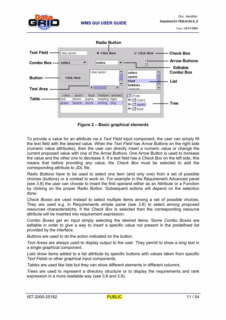
Before describing in detail each panel, we provide hereafter some principles about meaning and usage of the basic Swing graphical elements used to build them. The panels are composed of different graphical components used to get inputs from user and/or to display outputs. These components are Text Fields, Radio Buttons, Check Boxes, Combo Boxes (editable or not), Arrow Buttons, Buttons, Text Areas, Lists, Tables and Trees.
IST-2000-25182 PUBLIC 10 / 54
Doc. Identifier:DataGrid-01-TEN-0143-0_0
WMS GUI USER GUIDE
Date: 24/11/2003
Text Field
Radio Button
Check Box
Arrow Buttons
List
Tree
Button
Combo BoxEditable
Combo Box
Table
Text Area
Figure 2 – Basic graphical elements
To provide a value for an attribute via a Text Field input component, the user can simply fill the text field with the desired value. When the Text Field has Arrow Buttons on the right side (numeric value attributes), then the user can directly insert a numeric value or change the current proposed value with one of the Arrow Buttons. One Arrow Button is used to increase the value and the other one to decrease it. If a text field has a Check Box on the left side, this means that before providing any value, the Check Box must be selected to add the corresponding attribute to JDL file. Radio Buttons have to be used to select one item (and only one) from a set of possible choices (buttons) or a context to work on. For example in the Requirement Advanced panel (see 3.8) the user can choose to insert the first operand either as an Attribute or a Function by clicking on the proper Radio Button. Subsequent actions will depend on the selection done. Check Boxes are used instead to select multiple items among a set of possible choices. They are used e.g. in Requirements simple panel (see 3.8) to select among proposed resources characteristichs. If the Check Box is selected then the corresponding resource attribute will be inserted into requirement expression. Combo Boxes get an input simply selecting the desired items. Some Combo Boxes are editable in order to give a way to insert a specific value not present in the predefined list provided by the interface. Buttons are used to do the action indicated on the button. Text Areas are always used to display output to the user. They permit to show a long text in a single graphical component. Lists show items added to a list attribute by specific buttons with values taken from specific Text Fields or other graphical input components. Tables are used like lists but they can show different elements in different columns. Trees are used to represent a directory structure or to display the requirements and rank expression in a more readable way (see 3.8 and 3.9).
IST-2000-25182 PUBLIC 11 / 54

Doc. Identifier:DataGrid-01-TEN-0143-0_0
WMS GUI USER GUIDE
Date: 24/11/2003
The JDL Editor has four buttons at the bottom of the window, these are: ‘Reset’, ‘View’ (before bottom Text Area), ‘Reset All’ and ‘View All’ (after bottom Text Area). ‘Reset’ resets all the values inserted for the attributes contained in the current working panel, restoring default values for the attributes that have one. ‘View’ shows a partial JDL file containing the attributes name and corresponding values inserted by the user in the current working panel. This way the user can add, remove, change attributes and see which will be the corresponding changes in the generated JDL file. ‘Reset All’ and ‘View All’ have the same meaning, but they operate on all panels. In particular if user press on ‘View All’ button, a Text Area (see Figure 3) is shown with the whole JDL generated from current settings. The text area is not editable, but the user can go back to continue building and modifying the JDL by pressing the provided ‘Back’ button.
Figure 3 - The JDL text area
IST-2000-25182 PUBLIC 12 / 54

Doc. Identifier:DataGrid-01-TEN-0143-0_0
WMS GUI USER GUIDE
Date: 24/11/2003
The JDL Editor has a menu bar that provides a set of functionalities. The bar has two menus: File Menu and Help Menu.
3.1. FILE MENU The File Menu provides the functionalities shown in the following picture:
Figure 4 - File Menu
The ‘Open File…’ menu item allows opening files. A File Chooser window appears to ask for the file to open. User can provide the name of the file or choose one, selecting it from the local file system. The JDL Editor can edit JDL files or job description written in xml according to the condor dtd. User can then choose the file to open from jdl or xml file types. If the user presses the Open button of the file chooser after the file selection, the selected file will be opened and checked for correctness. If the file contains errors, they will be shown to the user, inside a warning message window. After closing this warning message window, user can review the errors simply selecting the ‘File Parsing Error(s)’ menu item. It is at this point possible to work on the file, adding or removing attributes or modifying their values. The ‘Save File’ menu item allows saving the generated JDL to a file. The file will be saved using the name of the originally opened file. If the JDL to save has been created directly in the JDL Editor, then a file name will be asked to the user proposing ‘job1’ as default. If the file already exists then the user will be prompt to ask for confirming save action. ‘Save File as…’ allows saving the JDL using the file name provided by the user. ‘File Parsing Error(s)’ is used to view the file parsing error(s) found during file opening/parsing operation. These error(s) will be shown inside the Text Area at the bottom of the JDL Editor window. This menu item is enabled only if the interface has found some errors during opening operation. ‘Exit’ item allows quitting the application. User is prompted for confirmation.
3.2. HELP MENU The ‘Help Topics’ menu item displays the content of the table of contents of the help pages. The ‘About’ menu item displays the JDL Editor version and the EDG copyright statement.
IST-2000-25182 PUBLIC 13 / 54

Doc. Identifier:DataGrid-01-TEN-0143-0_0
WMS GUI USER GUIDE
Date: 24/11/2003
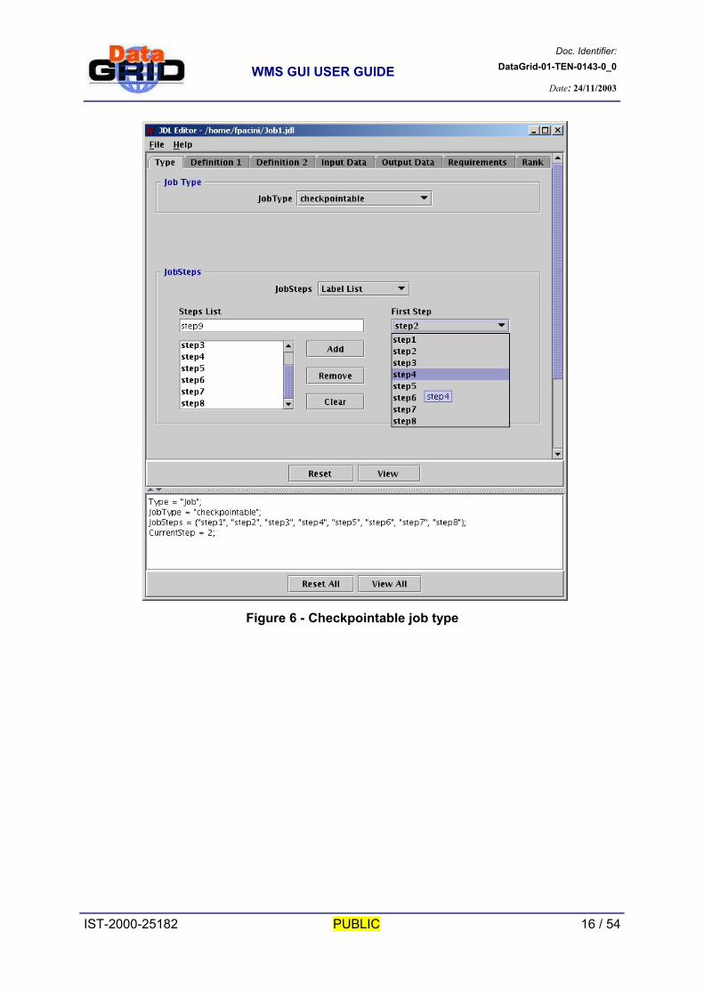
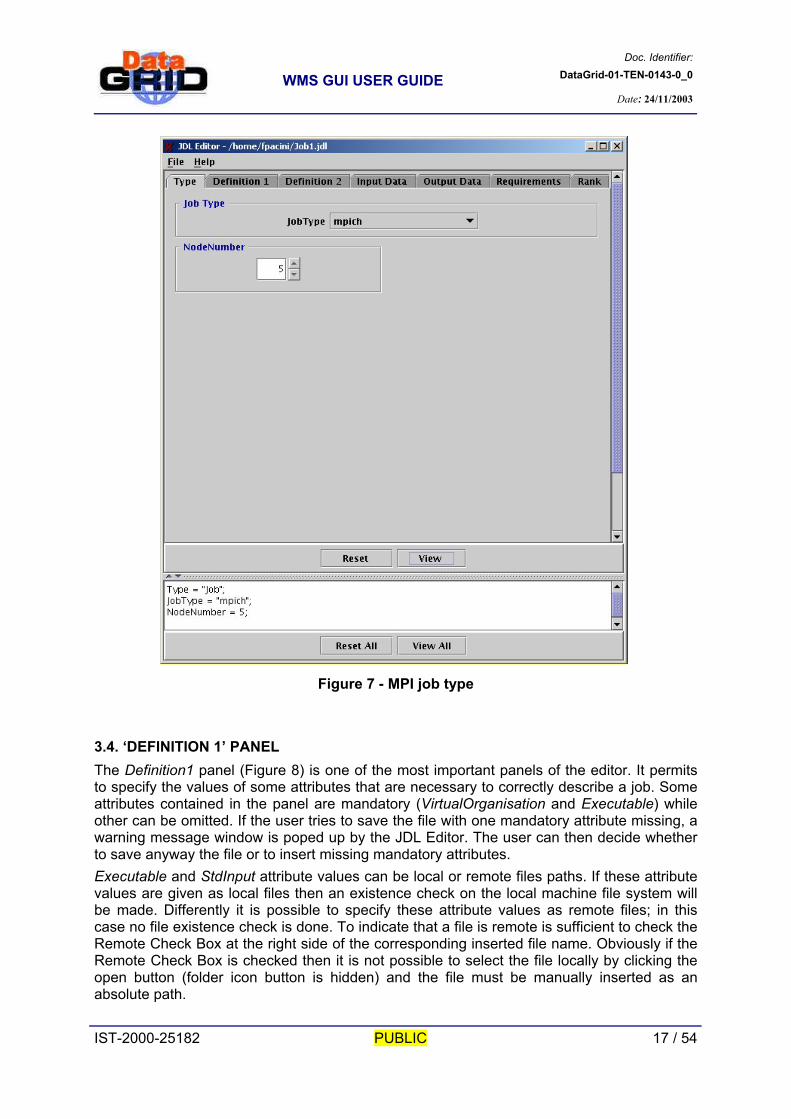
3.3. ‘TYPE’ PANEL The Type panel is used to describe the type of the job and to set some attribute values directly bound to it. The Job type can be chosen among one of the following values:
normal interactive partitionable checkpointable mpich checkpointable/interactive checkpointable/mpich
Depending on the job type, different input components will be shown to provide some specific attribute values. If the job is interactive then the user can specify the ListenerPort attribute (Figure 5). If the job is checkpointable (Figure 6) the user can specify the JobSteps attribute as a list (Label List) or as a numeric value (FirstStep and LastStep). If the job is mpich the user can use NodeNumber attribute to specify the minimum required number of computational nodes (Figure 7).
IST-2000-25182 PUBLIC 14 / 54

Doc. Identifier:DataGrid-01-TEN-0143-0_0
WMS GUI USER GUIDE
Date: 24/11/2003
Figure 5 - Interactive job type
IST-2000-25182 PUBLIC 15 / 54
Doc. Identifier:DataGrid-01-TEN-0143-0_0
WMS GUI USER GUIDE
Date: 24/11/2003
Figure 6 - Checkpointable job type
IST-2000-25182 PUBLIC 16 / 54
Doc. Identifier:DataGrid-01-TEN-0143-0_0
WMS GUI USER GUIDE
Date: 24/11/2003
Figure 7 - MPI job type
3.4. ‘DEFINITION 1’ PANEL The Definition1 panel (Figure 8) is one of the most important panels of the editor. It permits to specify the values of some attributes that are necessary to correctly describe a job. Some attributes contained in the panel are mandatory (VirtualOrganisation and Executable) while other can be omitted. If the user tries to save the file with one mandatory attribute missing, a warning message window is poped up by the JDL Editor. The user can then decide whether to save anyway the file or to insert missing mandatory attributes. Executable and StdInput attribute values can be local or remote files paths. If these attribute values are given as local files then an existence check on the local machine file system will be made. Differently it is possible to specify these attribute values as remote files; in this case no file existence check is done. To indicate that a file is remote is sufficient to check the Remote Check Box at the right side of the corresponding inserted file name. Obviously if the Remote Check Box is checked then it is not possible to select the file locally by clicking the open button (folder icon button is hidden) and the file must be manually inserted as an absolute path. IST-2000-25182 PUBLIC 17 / 54

Doc. Identifier:DataGrid-01-TEN-0143-0_0
WMS GUI USER GUIDE
Date: 24/11/2003
When StdOutput or StdError are specified it is possible to insert them also in the OutputSandbox list, to have the possibility to retrieve them later, just selecting the corresponding Check Box named “Add to Output Sandbox”. The InputSandbox file list (i.e. the files that have to be staged from the UI to the remote CE) can be filled/modified/cleared using buttons on the right side of the corresponding list. Files to insert can be chosen navigating the file system with the file chooser. The same applies to the OutputSandbox file list with the only difference that paths of files to be inserted have to be written by hand as they are refer to the file system of the remote resource where the job will run.
Figure 8 - Definition1 panel
3.5. ‘DEFINITION 2’ PANEL Using this panel (Figure 9) is possible to define the environment variables needed during job execution. Name field is used to insert the name of the variable (it must be unique), while
IST-2000-25182 PUBLIC 18 / 54

Doc. Identifier:DataGrid-01-TEN-0143-0_0
WMS GUI USER GUIDE
Date: 24/11/2003
Value field is used to provide the value. To add a new variable into the Environment attribute list, provide name and value and press the ‘Add’ button; to remove one or more variables, select the variable(s) to remove and press the ‘Remove’ button; to clear all variable list just press ‘Clear’ button. If the value or the name of an inserted variable needs to be modified, it is possible to make some changes simply double clicking on the corresponding list item. The name and the value of the variable are inserted in the corresponding Text Fields and can be modified. Modifications are applied pressing the ‘Replace’ button. The ‘Definition2’ panel also allows setting through dedicated Text Fields the host fqdn of the Server for Credentials Delegation (MyProxyServer) and the address of the user Home Location Register (HLRLocation) in the format <host fqdn>:<port>:<X509contact string>. If no value is provided no attribute is inserted. Finally it is possible to set the value of the RetryCount attribute. To do this it is necessary to select the corresponding Check Box and either inserting directly the needed value or use the up and down Arrow Buttons. If a negative value or a non-integer value is inserted then the default value will be restored.
Figure 9 - Definition2 panel
IST-2000-25182 PUBLIC 19 / 54

Doc. Identifier:DataGrid-01-TEN-0143-0_0
WMS GUI USER GUIDE
Date: 24/11/2003
3.6. ‘INPUT DATA’ PANEL The Input data panel (Figure 10) is divided into two parts tightly connected. The first part is used to provide the value(s) of the list attribute InputData. The second part is used to provide the value(s) of the list attribute DataAccessProtocol. A list attribute can be composed of one or more elements. InputData and DataAccessProtocol attributes must be specified together before submitting the job. The buttons ‘Add’, ‘Remove’ and ‘Clear’ near the lists perform the corresponding operations.
Figure 10 - Input Data panel
IST-2000-25182 PUBLIC 20 / 54

Doc. Identifier:DataGrid-01-TEN-0143-0_0
WMS GUI USER GUIDE
Date: 24/11/2003
3.7. ‘OUTPUT DATA’ PANEL This panel (Figure 11) can be used to describe output data information, i.e. the files generated by the job during its execution that have to be automatically uploaded and registered into the Grid by the WMS. Each OutputData entry consists of three items: Output File, Storage Element and Logical File Name. Output File is manadatory for each entry, moreover Output File and Logical File Name must be unique. The buttons “Add”, “Remove”, “Replace” and “Clear” perform the corresponding operations. This panel also allows setting the OutputSE JDL attribute through the Output Storage Element Text Field. It represents the SE where the job wants to save the files generated during its execution. Please note that the value of this attribute (as explained in [A3]) influences the match making as it makes the job be submitted only to CEs having the specified SE as a close SE.
Figure 11 - Output Data panel
IST-2000-25182 PUBLIC 21 / 54

Doc. Identifier:DataGrid-01-TEN-0143-0_0
WMS GUI USER GUIDE
Date: 24/11/2003
3.8. ‘REQUIREMENTS’ PANEL requirements is one of the most important attribute present in a JDL file. It is used to describe the resources needed to run the job properly. The value of requirement attribute is represented by a logical expression where operands are combined with Boolean operators (namely AND, OR, AND NOT, OR NOT). The Requirements panel permits to describe the resources using two different approaches (different GUI panels): “Simple” and “Advanced”. The Simple panel (Figure 12) is composed of different group of predefined conditions. The panel contains Text Fields and Check Boxes. If a Text Field has filled by the user, or a Check Box is selected, the corresponding condition will be added to the requirements expression. All conditions are ANDed among them. The Simple panel contains also Check Boxes where no value has to be specified as they are referring to resources characteristics described by Booleans in the IS.
Figure 12 - Requirements Simple panel
IST-2000-25182 PUBLIC 22 / 54

Doc. Identifier:DataGrid-01-TEN-0143-0_0
WMS GUI USER GUIDE
Date: 24/11/2003
To use advanced approach it suffices to press “Advanced >>” button to go to the JDL Editor requirements Advanced panel. If the simple panel contains some user settings then a warning message will be shown asking for a user choice. In particular user can import simple panel settings in order to use them into the Advanced panel or discard them.
Figure 13 - Simple to Advanced
To return to Simple panel the “<< Simple” button has to be pressed. If the user has created an expression tree in the Advanced panel then the tree will be stored and a message will be shown to inform the user. Saved advanced tree will be presented to the user if he will come back to advanced panel without importing single panel settings.
Figure 14 - Advanced to Simple
With the Advanced panel (Figure 15) is possible to define a more complex requirements attribute expression. The expression is represented with a logical tree. The logical tree is composed of:
a root node (Exp node) sub-expression nodes (SubExp nodes) operand nodes operator nodes
IST-2000-25182 PUBLIC 23 / 54

Doc. Identifier:DataGrid-01-TEN-0143-0_0
WMS GUI USER GUIDE
Date: 24/11/2003
Figure 15 - Requirements Advanced panel
The ‘Add’ button inserts two or four nodes, depending on the logical operator of the adding level. The adding level is the level of the selected node. If no node is selected then the adding node will be root node. If the logical operator of the adding level is the same operator selected by the user, then add operation inserts an operator node and an operand node in the same tree level of the adding node. If the operand of the tree level of which the selected node belongs is different from the one selected by the user, then a sub expression node is created with a sub tree representing the sub expression provided; four nodes will be inserted: one sub expression node, two operand nodes and an operator node between them. The Requirements Advanced panel is composed of three different parts: “First Operand” and “Second Operand” of the condition to be built, and “Expression Tree”. In the first part of the panel user can insert the first parameter node and in the second one the second parameter node. The last part of the panel shows the expression tree. The “Relation” combo box between first operand and second operand is used to select the relation among first and second parameters values. The first operand can be an attribute or a function. If the attribute or the function represent a Boolean value then it can be preceded by a NOT operator simply selecting the corresponding “Not” Check Box. The second operand can be an attribute, a
IST-2000-25182 PUBLIC 24 / 54

Doc. Identifier:DataGrid-01-TEN-0143-0_0
WMS GUI USER GUIDE
Date: 24/11/2003
function or a user inserted value. The second operand type must be same type as the first operand type. This is a necessary condition because all evaluated operand nodes must produce a Boolean value. If the first operand can be itself evaluated to a Boolean (e.g. the selected resource attribute is Boolean) then the second operand is disabled because it is not needed. If a parameter is selected to be an attribute (i.e. a resource attribute) then the user can choose the name of the attribute using the Combo Box provided by the interface. If the parameter is a function, then the user has to select the name of the function among the supported ones and provide the parameters needed by that function. The function’s parameters Combo Boxes are editable. This means that user can select one of the parameters provided or directly insert one. If during an add operation one parameter is missing then a warning message will be shown. Inserted parameters must be of the same type as the type needed by the selected function. The type of the attributes needed is shown inside the brackets, after the name of the function in the function Combo Box. Possible types for function parameters are:
S stands for a String value (a text) I stands for an integer value F stands for a float value L stands for a list value V indicates a generic value (e.g. it depends on the type of another parameter)
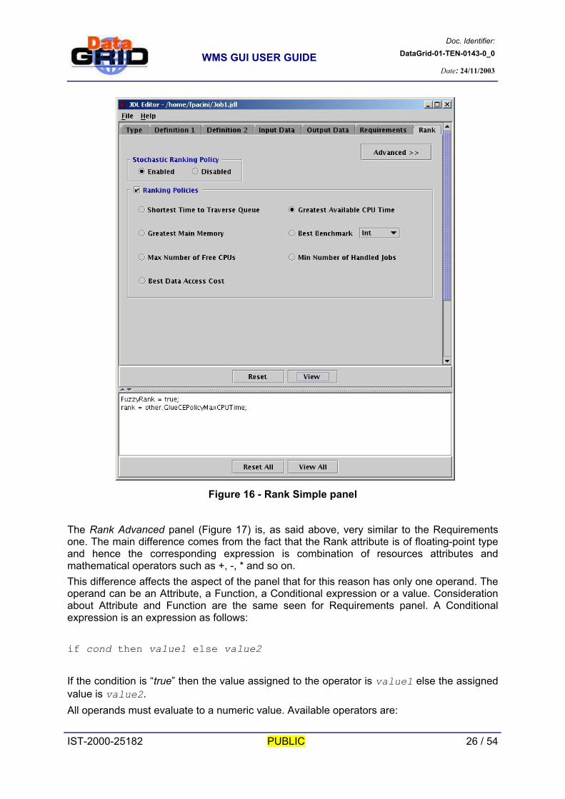
3.9. ‘RANK’ PANEL The Rank panel is similar to the Requirements panel. It has two different ways to define the expression of the rank attribute: “Simple” and “Advanced”. The Simple panel (Figure 16) is very essential. The user can select to activate Stochastic Ranking Policy, through the dedicated Check Box (Ranking Policies), and then choose among a predefined set of ranking policies. The proposed ranking policies (i.e. “among the suitable resources pick out the one with”) are:
Shortest Time to Traverse Queue Greatest Main Memory Max Number of Free CPUs Best Data Access Cost Greatest Available CPU Time Best Benchmark Min Number of Handled Jobs
IST-2000-25182 PUBLIC 25 / 54
Doc. Identifier:DataGrid-01-TEN-0143-0_0
WMS GUI USER GUIDE
Date: 24/11/2003
Figure 16 - Rank Simple panel
The Rank Advanced panel (Figure 17) is, as said above, very similar to the Requirements one. The main difference comes from the fact that the Rank attribute is of floating-point type and hence the corresponding expression is combination of resources attributes and mathematical operators such as +, -, * and so on. This difference affects the aspect of the panel that for this reason has only one operand. The operand can be an Attribute, a Function, a Conditional expression or a value. Consideration about Attribute and Function are the same seen for Requirements panel. A Conditional expression is an expression as follows: if cond then value1 else value2 If the condition is “true” then the value assigned to the operator is value1 else the assigned value is value2. All operands must evaluate to a numeric value. Available operators are: IST-2000-25182 PUBLIC 26 / 54

Doc. Identifier:DataGrid-01-TEN-0143-0_0
WMS GUI USER GUIDE
Date: 24/11/2003
+ addition - subtraction * multiplication / division % remainder
Figure 17 - Rank Advanced panel
3.10. ‘UNKNOWN’ PANEL The Unknown panel shows all attributes found in a JDL file opened by the user, which the JDL Editor is unable to recognize (i.e. they are not among the supported attributes). The
IST-2000-25182 PUBLIC 27 / 54

Doc. Identifier:DataGrid-01-TEN-0143-0_0
WMS GUI USER GUIDE
Date: 24/11/2003
panel text area is editable so that it is possible to add/remove/modify “unknown” JDL attributes. Specification of supported attributes through this panel is not allowed.
Figure 18 - Unknown Attributes panel
IST-2000-25182 PUBLIC 28 / 54

Doc. Identifier:DataGrid-01-TEN-0143-0_0
WMS GUI USER GUIDE
Date: 24/11/2003
IST-2000-25182 PUBLIC 29 / 54

Doc. Identifier:DataGrid-01-TEN-0143-0_0
WMS GUI USER GUIDE
Date: 24/11/2003
4. CREDENTIALS All interactions between WMS components, especially those that are network-separated, are mutually authenticated. Depending on the specific interaction, an entity authenticates itself to the other peer using either its own credentials or a delegated user credentials or both. In particular when the User Interface passes a job to the Network Server, the GUI authenticates using a delegated user credentials whereas the NS uses its own service credentials. The same applies for the interactions between the GUI and the LB for monitoring the job status. Due to this, to take advantage of all the functionalities provided by the Job Monitor and the Job Submitter applications, the user has to own a valid X.509 proxy credentials needed for the authentication and authorization processes. When the user launches the Job Monitor or the Job Submitter a Credentials window (Figure 19) is displayed reporting the current security environment settings and the proxy credentials information (if a valid proxy credentials is found in the designated location). If the found proxy credentials contains VOMS extensions, then the default VO (i.e. the first VO) contained in the proxy VOs list is extracted from the credentials and presented to the user in a Combo Box. If the found proxy credentials does not contain VOMS extensions then a proposed VOs list is read from the GUI configuration. In the first case user can only choose the proposed VO as it is assumed to work in a VOMS-aware environment whilst in the latter case she/he can also insert and select a different one not proposed by the interface and provide afterwards all needed configuration information. The VOMS Extension Present Text Field indicates whether the selected proxy has a VOMS extension or not. The proxy credentials information fields are shown in the bottom part of the Credentials window. In particular they are: certificate Subject, proxy time left, key length and proxy type.
Figure 19 - User Credentials window
Once the proxy file and the VO to work for have been selected the user can proceed with the start-up of the application. The Credentials window has three buttons: ‘Exit', ‘Default’ and ‘Ok’. ‘Exit’ button quits the application asking to confirm the choice. The ‘Default’ button loads all default security
IST-2000-25182 PUBLIC 30 / 54

Doc. Identifier:DataGrid-01-TEN-0143-0_0
WMS GUI USER GUIDE
Date: 24/11/2003
environment settings (e.g. proxy file path). The ‘Ok’ button checks if the selected proxy credentials is valid and starts the actual Job Monitor or Job Submitter application.
IST-2000-25182 PUBLIC 31 / 54

Doc. Identifier:DataGrid-01-TEN-0143-0_0
WMS GUI USER GUIDE
Date: 24/11/2003
5. JOB MONITOR With the Job Monitor application the user can retrieve and display logging and bookkeeping information about all submitted jobs she/he owns. The user can directly insert the job ids of the jobs to be monitored, load a job ids list from a file or get the job ids from the available Logging & Bookkeeping Servers.
Figure 20 - Job Monitor (JobIds panel)
The Job Monitor application has two different panels. The first panel – JobId panel (Figure 20) – is the panel that is shown on start-up. This panel contains a Job Ids Table where are displayed the job identifiers loaded by the user. The second panel – Job Status panel (Figure 21) – contains instead the ‘Job Status’ table reporting, besides the job ids, the current status of the job together with some additional bookkeeping information. This panel is shown when the user select one or more jobs from the first panel and then ask for the status of the job(s) through the ‘Job Status’ button at the bottom right of the panel (or selecting the same item in the Job Ids Table popup menu - displayed clicking on the table with the right button of the mouse).
IST-2000-25182 PUBLIC 32 / 54

Doc. Identifier:DataGrid-01-TEN-0143-0_0
WMS GUI USER GUIDE
Date: 24/11/2003
Figure 21 - Job Monitor (Job Status panel)
The Job Monitor has a menu bar with five menus: ‘Job’, ‘Checkpoint’, ‘Credentials, ‘Sort’ and ‘Help’. The ‘Job’ menu has some items that are available only in the first panel whilst the ‘Sort’ menu is available only for the second panel.
5.1. JOB MENU The Job menu (Figure 22) has 7 items:
IST-2000-25182 PUBLIC 33 / 54

Doc. Identifier:DataGrid-01-TEN-0143-0_0
WMS GUI USER GUIDE
Date: 24/11/2003
Figure 22 – Job Monitor Job Menu
− ‘Open Job Ids List File…’ allows the selection of a file containing a list of Job Ids. All
job ids in the file will be inserted into the Job Ids Table. If the Job Ids Table already contains other Job Ids, new Job Ids will be added. (Only first panel)
− ‘Save Job Ids List File…’ allows instead saving all job ids present in the Job Ids Table into a file.
− ‘Save Selected Job Ids List File…’ saves all currently selected Job Ids in a new Job Ids list file.
− ‘Get Job Ids from LB’ retrieves all job ids from the selected Logging & Bookkeeping Server. When this menu item is selected, a list of all possible LB Servers available is shown. If more than one LB Server is available then the item “- All Available LB Servers -“ is also provided. User can select the desired Server to get job ids from. User can get job ids from different Servers; all job ids will be inserted in the same list. (Only first panel)
− ‘Preferences’ is used to change preferences as shown in section 6.6. − ‘Exit’ quits the application keeping the current context so that the application can be
restarted with current situation. The user is prompted for confirmation. − Exit & Clean Context’ quits the application and cleans-up the current context. The
user is prompted for confirmation.
5.2. CHECKPOINT MENU The Checkpoint menu (Figure 23) has two items: ‘Open Checkpoint State…’ and ‘Retrieve Checkpoint State…’.
Figure 23 - Checkpoint Menu
With the first item it is possible to open and read a checkpoint state file stored on the local file system. The file is opened and shown in a different window, closable by the user. ‘Retrieve Checkpoint State…’ allows retrieving a job checkpoint state for a checkpointable job previously submitted. This is only allowed for checkpointable jobs. To retrieve a checkpoint state it is necessary to provide a job id, identifying a checkpointable job, and an integer number representing the number of the state the user want to retrieve
IST-2000-25182 PUBLIC 34 / 54

Doc. Identifier:DataGrid-01-TEN-0143-0_0
WMS GUI USER GUIDE
Date: 24/11/2003
(State). For example State number ‘0’ means last checkpoint state, ‘1’ means checkpoint state before last and so forth.
Figure 24 - Retrieve Checkpoint State
5.3. CREDENTIALS MENU The Credentials menu (Figure 25) has two possible choices: ‘Info’ and ‘Select’.
Figure 25 - Credentials Menu
− ‘Info’ shows all available current proxy credentials information. − ‘Select’ allows changing the current working Proxy credentials file (and this also
allows changing the current working Virtual Organisation). The new selected Proxy credentials must anyway have the same DN. If the current Proxy certificate contains VOMS extensions then user can only work for the VO proposed by the interface Combo Box (the default VO contained inside the VOMS extension). If no VOMS extension is present then the user can select a VO among the proposed ones or directly insert a new one. The ‘Select’ item is enabled only if the Job Monitor is running in stand-alone mode or if the Job Submitter has been exited. If the Job Submitter is running then it is possible to do ‘Select’ operation only from Job Submitter Credentials menu and this will affect also the Job Monitor that will be closed as the current context is no more valid. The user can restart it afterwards from the Job Submitter.
5.4. SORT MENU The Sort menu (Figure 26) provides some sorting functionalities. This menu is present in the menu bar only if the Job Monitor second panel is displayed (Job Status panel). User can sort all job displayed into the Job Status Table choosing the sorting column on which the sorting
IST-2000-25182 PUBLIC 35 / 54

Doc. Identifier:DataGrid-01-TEN-0143-0_0
WMS GUI USER GUIDE
Date: 24/11/2003
operation has to be done: 'Job Id', 'Job Type', 'Status', 'Submitted At' (Submission Time), 'Destination'.
Figure 26 - Sort Menu
‘Table Adding Order’ is an alternative choice. If this choice is selected, the jobs are ordered following the order used to insert the jobs in the table.
5.5. HELP MENU See section 3.2.
5.6. SETTING PREFERENCES Job Monitor preferences can be set choosing the ‘Preferences’ item from the Job menu: a preferences window is shown (Figure 27). It allows inserting the host address and port number of the LB Servers available for the VO the user is working for. The LB contacts will be used to get Job Ids from. Combination of Address and Port number must be unique. All user-provided LB Servers are inserted as possible choice of the ‘Get Job Ids From LB’ functionality present in the Job menu. To clear address and port field it suffices clicking on the ‘Clear’ button at the bottom of the fields. To add a Server is sufficient to insert desired server address and port number and the click on the ‘Add’ button. To remove one or more server, just select the server(s) from the list and click on ‘Remove’ button. To clear all the table click on ‘Clear’ button near the table. ‘All’ and ‘None’ buttons are used respectively to select or deselect all servers in the list. ‘Replace’ is used to replace the selected entry with the new one defined by the value inserted in the Address and Port fields. If the user double IST-2000-25182 PUBLIC 36 / 54

Doc. Identifier:DataGrid-01-TEN-0143-0_0
WMS GUI USER GUIDE
Date: 24/11/2003
click a Table row then the value inserted in the row will be written inside the Address and Port fields. This is useful when users have to make some changes to a server or want to add one that has just slight differences in address or port. ‘Update Rate’ has the function to set the number of minutes (say n) from one update to the next one. The Job Monitor automatically updates all job status information every n minutes so users don’t have to repeatedly press the update button to get updated job status information. Update rate can be directly inserted or set using the two Arrow Buttons. Minimum Update Rate value is one minute. It is important to note that this kind of ‘polling’ of information from the LB will be replaced with an asynchronous update on job status changes when the notification service from R-GMA will be available. To apply the selected preferences two buttons are provided: the ‘Apply’ button applies preferences leaving the preferences window opened, while ‘Ok’ button applies preferences and closes the window. All applied preferences will be saved into a user preferences file. The Preferences window has one button to load ‘Default’ preferences settings. At start-up application preferences are always set to ‘User’ preferences, read from a previously created user preferences file (if any).
Figure 27 - Job Monitor Preferences
5.7. MONITORING JOBS To monitor submitted jobs the first step to do is to insert the job ids in the first panel Job Id Table (Figure 20). Then the user has to select, from the Job Ids Table, the jobs she/he wants to follow-up and click on the ‘Job Status’ button or alternatively selecting ‘Job Status’ item from Job Id Table popup menu (displayed clicking on the table with the right button of the mouse).
IST-2000-25182 PUBLIC 37 / 54

Doc. Identifier:DataGrid-01-TEN-0143-0_0
WMS GUI USER GUIDE
Date: 24/11/2003
This makes the Job Monitor switch to the Job Status panel (Figure 21) where the selected jobs are displayed together with basic Job Status information. The Job Status table has five columns:
Job Id EDG identifier of the monitored job Job Type job type Status current Status of the job. The most important states are
presented with a state specific background color to help the user to easily identify them.
Submitted At the Submission Time of the job (when the job has been submitted to the Network Server)
Destination the Destination of the job (where the job is running or has been scheduled to run)
In order to get detailed information about the job status, it is possible to select a single job from the table and then click on the ‘Details’ button (or alternatively selecting ‘Details’ item from popup menu). This will show a different window – the Job Status Details window (Figure 28) – with all information currently available about the selected job. This window is divided into two parts: ‘Common Info’ and ‘Detailed Info’. The first part contains the most important information about the job, such as Status, Type, Job Owner, etc. The second part contains other information that is secondary. These peaces of information are inserted into the table only if they are available.
IST-2000-25182 PUBLIC 38 / 54

Doc. Identifier:DataGrid-01-TEN-0143-0_0
WMS GUI USER GUIDE
Date: 24/11/2003
Figure 28 - Job Status Details
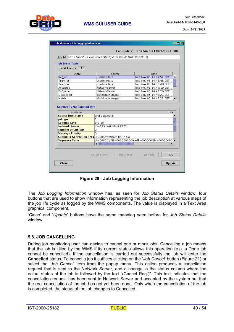
At the bottom of the Job Status Details window are present four buttons. These buttons are used to display information representing the job description at various steps of the job life cycle as logged by the WMS components. When one of these peaces of information is available, the corresponding button is enabled. Clicking on this button user can see the classad in a Text Area graphical component from where he can come back clicking on the ‘Back’ button provided. The ‘Close’ button closes the details window while the ‘Update’ button updates all information actually displayed in the window, asking new information to the relevant Logging & Bookkeeping Server. During its life cycle, a submitted job is handled by several components of the WMS, each one producing and logging job related information (events) to the LB. All these events can be displayed pressing on ‘Log Info’ button of the Job Status panel (or alternatively selecting ‘Log Info’ item from popup menu). This button makes a new window – the Job Logging Information window (Figure 29) – opened with all recorded events. This window is divided into two parts: the ‘Job Event Table’ and the ‘Selected Event Logging Info’ table. The first part shows in a table all events names, the source of the event and the time when the event has happened. The second part shows all the attributes that describe the event selected in the first part (Job Events Table).
IST-2000-25182 PUBLIC 39 / 54
Doc. Identifier:DataGrid-01-TEN-0143-0_0
WMS GUI USER GUIDE
Date: 24/11/2003
Figure 29 - Job Logging Information
The Job Logging Information window has, as seen for Job Status Details window, four buttons that are used to show information representing the job description at various steps of the job life cycle as logged by the WMS components. The value is displayed in a Text Area graphical component. ‘Close’ and ‘Update’ buttons have the same meaning seen before for Job Status Details window.
5.8. JOB CANCELLING During job monitoring user can decide to cancel one or more jobs. Cancelling a job means that the job is killed by the WMS if its current status allows this operation (e.g. a Done job cannot be cancelled). If the cancellation is carried out successfully the job will enter the Cancelled status. To cancel a job it suffices clicking on the ‘Job Cancel’ button (Figure 21) or select the ‘Job Cancel’ item from the popup menu. This action produces a cancellation request that is sent to the Network Server, and a change in the status column where the actual status of the job is followed by the text “(Cancel Req.)”. This text indicates that the cancellation request has been sent to Network Server and accepted by the system but that the real cancellation of the job has not yet been done. Only when the cancellation of the job is completed, the status of the job changes to Cancelled.
IST-2000-25182 PUBLIC 40 / 54

Doc. Identifier:DataGrid-01-TEN-0143-0_0
WMS GUI USER GUIDE
Date: 24/11/2003
5.9. GETTING JOB OUTPUT During its execution a job can produce some output files that can be retrieved by the user if previously listed in the JDL OutputSanbox attribute. The output files are retrieved from the Network Server node and stored on the submitting machine local storage devices. To get the output of one or more jobs it suffices clicking on the ‘Job Output’ button (Figure 21) or select ‘Job Output’ item from popup menu. The interface will ask for a path on the local machine where to store the output files of all the current selected jobs. For every job a different directory will be created in the specified path. The job output retrieval is only allowed if the job is in the Done state as it is the only case when such files are available on the Network Server node.
IST-2000-25182 PUBLIC 41 / 54

Doc. Identifier:DataGrid-01-TEN-0143-0_0
WMS GUI USER GUIDE
Date: 24/11/2003
6. JOB SUBMITTER The Job Submitter is the main component of the WMS Java GUI. It has the main goal of allowing job submission, but since it can start the other GUI components, also allows editing JDL files through the JDL Editor and monitoring jobs through the Job Monitor. The Job Submitter (Figure 30) is composed of one or more panels each one referring to a specific Network Server. User can specify all the Network Servers she/he wants to contact to submit her/his jobs using the Job Submitter preferences (section 6.6). For each provided NS a different panel is added to the main window. Network Server information is shown in the upper part of the window while jobs to submit are inserted in the Job Table.
Figure 30 - Job Submitter
The Job Submitter main window has three buttons: ‘Editor’, ‘Monitor’ and ‘Submit’. The ‘Editor’ button opens a JDL Editor to edit a new JDL file. If before clicking on the button a single job is selected within the Job Table, then the JDL Editor will be opened loading the selected job. The ‘Monitor’ button allows the user to start the Job Monitor application from the Job Submitter. If one or more submitted jobs are selected within the Job Table, then the Job monitor is opened and the selected jobs are automatically inserted into the Job Status Table in the Job Monitor second panel (Figure 21). If no jobs are selected or if no jobs are already submitted, then the Job Monitor is opened with no jobs, displaying the first panel (Figure 20).
IST-2000-25182 PUBLIC 42 / 54

Doc. Identifier:DataGrid-01-TEN-0143-0_0
WMS GUI USER GUIDE
Date: 24/11/2003
The ‘Submit’ button submits to the current NS all the jobs selected in the Job Table. The Job Table provides a popup menu with different functionalities (Figure 31). They are mostly edit functionalities, i.e. ‘Cut’, ‘Copy’, ‘Paste’, ‘Copy To’, ‘Move to’, ‘Remove’, ‘Clear’, ‘Select All’, ‘Select None’ and ‘Invert Selection’. It also provides some other functionalities described here below.
Figure 31 - Job Table popup menu
The ‘Rename’ item simply allows changing the name of a job inserted into Job Table. This operation is allowed only if the job is not submitted. Jobs renaming can be done selecting the job to rename and choosing the ‘Rename’ item from popup menu. A new window is shown asking for the new name of the job. The name must be different from the other ones currently present into Job Table. ‘Listmatch’ can be used to get the identifiers (CE Id) of all Computing Elements that satisfy job requirements and (if needed) to make an association between a job and a Computing Element for direct submission to it. The ‘Listmatch’ items has four possible choices: − ‘CE Id list from IS’ provides the list of CE satisfying job requirements. The request is sent
to NS that contacts the IS for performing the match making. It allows moreover the selection of a Computing Element to associate to a job from the obtained list of CEs. The found CEs are shown in a table with the corresponding rank value. The displayed CE list can be saved to a CE Ids list file.
− ‘CE Id list from file’ permits to select a CE to associate to a job from a list of Computing Element identifiers contained in a file.
− ‘View CE Id Selection’ displays the identifier of the Computing Element associated to a job.
− ‘Remove CE Id Selection’ removes the association between the job and the Computing Element.
IST-2000-25182 PUBLIC 43 / 54

Doc. Identifier:DataGrid-01-TEN-0143-0_0
WMS GUI USER GUIDE
Date: 24/11/2003
The ‘Submit’ item has the same functionality of the ‘Submit’ button. The job submission can be performed only if the job is not already submitted; this is indicated by the ‘Job Id’ column of the Job Table: “NOT SUBMITTED” says the job has not yet been submitted, “Submitting…” says that job submission is on-going and finally the presence of the EDG job id means the job has been already submitted successfully. If the user wants to submit a different job with the same JDL, she/he can either open again the file, adding it as a different job in the Job Table, or copy the job in the desired NS panel. The submit operation take all not submitted selected jobs (i.e. multiple selection is allowed) and submits them to the corresponding NS address shown inside Network Server Info frame. The Logging & Bookkeeping Servers storing the job status information will be choosen for each job in a round robin fashion (in order to distribute load) among the ones provided during preferences settings. For the jobs whose submission failed for some reason, no job id is associated and the job is kept marked as “NOT SUBMITTED”. The user can then try to submit these jobs again. ‘Send to Monitor’ adds the submitted jobs selected within the Job Table into the Job Monitor Job Status Table (Figure 21). If no Job Monitor is opened then an instance of it is started. The result of this operation has some differences from the operation done when ‘Monitor’ button is pressed. ‘Send to Monitor’ doesn’t open any Job monitor instance if no submitted jobs are selected from Job Table. ‘Open in Editor’ has the same function of the ‘Editor’ button described in section 6. The ‘Interactive Console’ item opens an interactive console for the jobs whose job type is “Interactive”, i.e. whose standard streams are forwarded from the remote CE to the UI node. An Interactive console is a window where the running job can display the output and ask for user for the input needed. The Interactive console window remains opened until the user closes it, even if the job has reached the Done status. The Interactive console can be opened at any time even if the job is not running, it will remain active listening on the job standard streams that will arrive when the job enters the Running status. The ‘Checkpoint’ items provides a set of functionalities reserved to checkpointable jobs, these are: − ‘Link Checkpoint State’ is used to link a Checkpoint state to a checkpointable. During
execution a checkpoint job produces partial execution results that are stored in order to retrieve them in a second time if necessary. Then a checkpoint job can be submitted linking it to a checkpoint state of a previously executed job. In this case the execution of the job begins from the point represented by the checkpoint state without doing precedent computation again. The checkpoint state is represented by a “.chkpt” file.
− ‘Unlink Checkpoint State’ removes the link, if any, previously associated with ‘Link Checkpoint State’ operation.
− ‘View Checkpoint State Link’ is used to view what checkpoint state file is linked to the checkpoint job and eventually read the contents of the file. This operation is possible only in the case a checkpoint state is associated to the job.
− ‘Retrieve Checkpoint State’ has the function to retrieve a checkpoint state and to save it to a checkpoint file on the local machine file system. The file can then be linked to a checkpointable job before submitting it.
The Job Submitter provides five menus (Figure 30): ‘Job’, ‘Edit’, ‘Checkpoint’, ‘Credentials’ and ‘Help’. They are described in the following sub-sections.
IST-2000-25182 PUBLIC 44 / 54

Doc. Identifier:DataGrid-01-TEN-0143-0_0
WMS GUI USER GUIDE
Date: 24/11/2003
6.1. JOB MENU The Job menu (Figure 32) provides a set of functionalities mostly referring to file operations (in some way a job is identified with a JDL file). The ‘New’ item opens a new JDL Editor window where the user can edit a JDL file to be added, as job, in the Job Submitter window. If more than one NS are provided then the job will be added in the Network Server panel currently selected before the selection of the ‘New’ item. When a JDL Editor is opened, the name of the Network Server panel and the name of the job are displayed in the title bar of the JDL Editor window.
Figure 32 - Job Menu
To open an existing JDL file the user can select the ‘Open in Editor…’ menu item. This will ask for the name of the JDL file and then display a new JDL Editor where the selected file is loaded. In the JDL Editor opened by the Job Submitter two new buttons are present: ‘Ok’ and ‘Close’.
Figure 33 - JDL Editor - OK/Close
IST-2000-25182 PUBLIC 45 / 54
Doc. Identifier:DataGrid-01-TEN-0143-0_0
WMS GUI USER GUIDE
Date: 24/11/2003
− ‘Ok’ button is used to confirm the edited JDL in order to add it as a job to the Job
Table. If the edited file doesn’t contain errors, a new job is added into the corresponding Network Server panel.
− ‘Close’ button simply close JDL Editor without adding any job. Only correct JDL files can be added as a job in a Network Server panel because, otherwise, they cannot be submitted.
The ‘Add…’ menu item adds a job to the Job Submitter Job Table without editing the corresponding JDL file. If the JDL doesn’t contains some mandatory attributes such as requirements and rank, and a default value is provided for them in the GUI configuration, then this attribute values are automatically inserted into the job before add it in the Job Table. If the file is not correct the job cannot be added and an error message is shown to the user. The job is added in the selected NS panel. It is also possible to select a directory to open. In this case all correct JDL and xml files contained in the directory will be parsed and added to the table. ‘Exit’ quits the application keeping the current context so that the application can be restarted with current situation. The user is prompted for confirmation. Exit & Clean Context’ quits the application and cleans-up the current context. The user is prompted for confirmation.
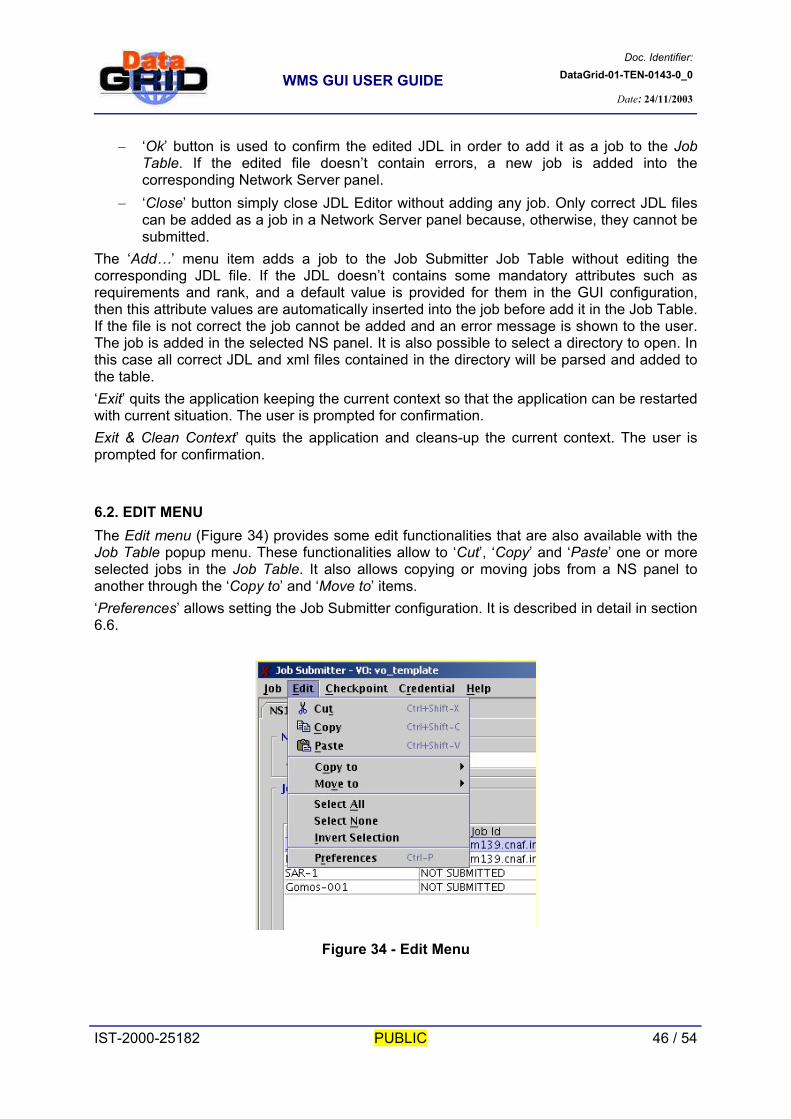
6.2. EDIT MENU The Edit menu (Figure 34) provides some edit functionalities that are also available with the Job Table popup menu. These functionalities allow to ‘Cut’, ‘Copy’ and ‘Paste’ one or more selected jobs in the Job Table. It also allows copying or moving jobs from a NS panel to another through the ‘Copy to’ and ‘Move to’ items. ‘Preferences’ allows setting the Job Submitter configuration. It is described in detail in section 6.6.
Figure 34 - Edit Menu
IST-2000-25182 PUBLIC 46 / 54
Doc. Identifier:DataGrid-01-TEN-0143-0_0
WMS GUI USER GUIDE
Date: 24/11/2003
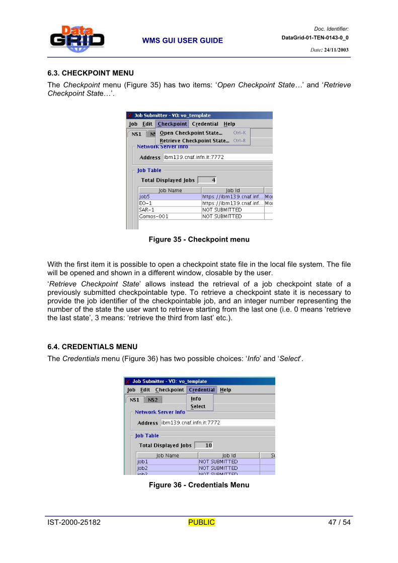
6.3. CHECKPOINT MENU The Checkpoint menu (Figure 35) has two items: ‘Open Checkpoint State…’ and ‘Retrieve Checkpoint State…’.
Figure 35 - Checkpoint menu
With the first item it is possible to open a checkpoint state file in the local file system. The file will be opened and shown in a different window, closable by the user. ‘Retrieve Checkpoint State’ allows instead the retrieval of a job checkpoint state of a previously submitted checkpointable type. To retrieve a checkpoint state it is necessary to provide the job identifier of the checkpointable job, and an integer number representing the number of the state the user want to retrieve starting from the last one (i.e. 0 means ‘retrieve the last state’, 3 means: ‘retrieve the third from last’ etc.).
6.4. CREDENTIALS MENU The Credentials menu (Figure 36) has two possible choices: ‘Info’ and ‘Select’.
Figure 36 - Credentials Menu
IST-2000-25182 PUBLIC 47 / 54

Doc. Identifier:DataGrid-01-TEN-0143-0_0
WMS GUI USER GUIDE
Date: 24/11/2003
− ‘Info’ shows all current proxy credentials available information. − ‘Select’ allows changing the current working Proxy credentials file (and this also
allows changing the current working Virtual Organisation). The new selected Proxy credentials must anyway have the same DN. If the current Proxy certificate contains VOMS extensions then user can only work for the VO proposed by the interface Combo Box (the default VO contained inside the VOMS extension). If no VOMS extension is present then the user can select a VO among the proposed ones or directly insert a new one. If the Job Monitor application is running during the “Select” operation, it will be closed (The user can restart it afterwards from the Job Submitter) as the current context is no more valid. Same thing happens to all opened JDL Editors.
6.5. HELP MENU See section 3.2.
6.6. SETTING PREFERENCES As said in section 6.2, the ‘Preferences’ item from the Job menu allows setting/modifying the Job Submitter configuration. Selecting that item makes a new window display, containing four panels. Any single panel groups preferences according to their specific meaning. More precisely, these panels are:
Network Server Logging & Bookkeeping JDL Defaults Logging
The Network Server panel (Figure 37) is the one allowing the insertion of the host name, port and Information Service Schema of each NS the user wants to contact to submit jobs. Name and Address must be unique. For any Network Server inserted in the table a Network Server panel will be added in the Job Submitter main window.
IST-2000-25182 PUBLIC 48 / 54

Doc. Identifier:DataGrid-01-TEN-0143-0_0
WMS GUI USER GUIDE
Date: 24/11/2003
Figure 37 - Preferences: Network Server panel
The Logging & Bookkeeping panel (Figure 38) permits insertion of the addresses (hostname and port) of the LB servers that the user wants to use for storing and retrieving job information. During the submission process all inserted LBs will be considered as available and choosen in such a way to distribute load among them.
Figure 38 - Preferences: L&B panel
IST-2000-25182 PUBLIC 49 / 54

Doc. Identifier:DataGrid-01-TEN-0143-0_0
WMS GUI USER GUIDE
Date: 24/11/2003
The JDL Defaults panel (Figure 39) allows the specification of the default values for some JDL attributes. These values are used by the JDL Editor (when started from the Job Submitter): If during a JDL file editing, the user doesn’t provide the values for these attributes, the default is automatically set by the GUI component.
Figure 39 - Preferences: JDL Defaults
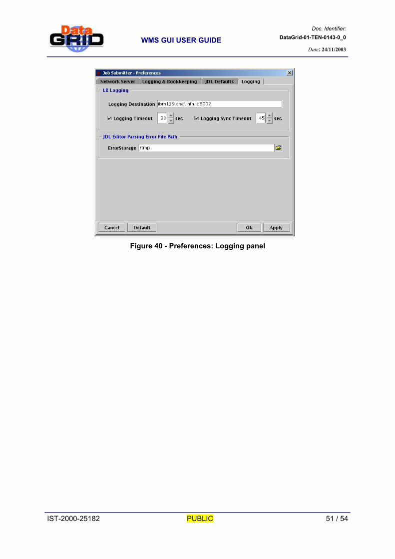
Default values for requirements, rank and rankMPI are specified referring to a specific Information Service Schema. For any of the supported schemas the user can specify different defaults. The rankMPI attribute has a specific meaning (see [A2], section 4.5.3.2). Other attributes for which user can specify a default value are: HLRLocation, MyProxyServer and RetryCount. The Logging panel (Figure 40) refers to settings related to the logging of job events from the user interface to the LB. Logging Destination is the address (<hostname>:<port>) of the locallogger (a deamon to be targeted by the Job Submitter when issuing logging calls). Logging Timeout and Logging Sync Timeout represent the number of seconds to wait during respectively asynchronous and synchronous logging operation. ErrorStorage is the path of the directory on the local file system where the JDL Editor will write log files about JDL parsing.
IST-2000-25182 PUBLIC 50 / 54
Doc. Identifier:DataGrid-01-TEN-0143-0_0
WMS GUI USER GUIDE
Date: 24/11/2003
Figure 40 - Preferences: Logging panel
IST-2000-25182 PUBLIC 51 / 54

Doc. Identifier:DataGrid-01-TEN-0143-0_0
WMS GUI USER GUIDE
Date: 24/11/2003
7. ANNEXES
7.1. GUI INSTALLATION AND CONFIGURATION The steps for installing and configuring the WMS GUI are described in detail in document [A2] sections 4.5.2.4, 4.5.3.2 and 4.5.4.2. Installation can be however performed downloading the gzipped tar file available at http://server11.infn.it/workload-grid and following steps reported here below. Once the file has been downloaded, to uncompress it, simply issue the following command: $ tar zxvf edg_java_gui_rpms_<version>.tar.gz
this creates a directory named edg_java_gui_<version> in the current working directory. Enter the directory $ cd edg_java_gui_<version>
and as root user, run the installation script edg_wl_ui_gui_rpms_install.sh: # ./edg_wl_ui_gui_rpms_install.sh
the required rpms package will be installed on you computer. These packages are (considering e.g. version 2.1.1-2): Java 1.4.1_01 package (Java 2 Development Kit 1.4):
− j2sdk_profile-1.4.1_01-1.noarch.rpm
− j2sdk-1.4.1_01-fcs.i586.rpm
Config packages:
− edg-wl-config-2.1.1-2.i486.rpm
− edg-wl-ui-config-2.1.1-2.i486.rpm
Classad:
− classads-jar-1.1-2.i386.rpm
Java common API (requestAd jar):
IST-2000-25182 PUBLIC 52 / 54

Doc. Identifier:DataGrid-01-TEN-0143-0_0
WMS GUI USER GUIDE
Date: 24/11/2003
− edg-wl-common-api-java-2.1.1-2.i486.rpm
Globus essentials from VDT package:
− vdt_globus_essentials-VDTALT1.1.8-9.i386.rpm
CoG (Globus Java Cog Kit):
− cog-jar-1.0-1_alpha.i386.rpm
Log4J 1.2.6:
− log4j-1.2.6-1jpp.noarch.rpm
EDG WMS UI Java API:
− edg-wl-ui-api-java-2.1.1-2.i486.rpm
EDG WMS Java GUI:
− edg-wl-ui-gui-2.1.1-2.i486.rpm
EDG WMS Common API:
− edg-wl-common-api-2.1.1-2.i486.rpm
Condor bypass (customised for EDG):
− edg-wl-bypass-2.5.3-18.i486.rpm
EDG WMS C/C++ logging API (LB producer & LB client):
− edg-wl-logging-api-c-2.1.1-2.i486.rpm
− edg-wl-logging-api-cpp-2.1.1-2.i486.rpm EDG Java Security Client API:
− bouncycastle-jdk14-1.19-2
IST-2000-25182 PUBLIC 53 / 54

Doc. Identifier:DataGrid-01-TEN-0143-0_0
WMS GUI USER GUIDE
Date: 24/11/2003
− edg-java-security-1.4.1-1
gcc 3.2.2 from EDG packaging:
− gcc3-3.2.2-edg1.i386.rpm When the installation has been completed successfully, follows instruction in [A2] section 4.5.3.2 and 4.5.4.2 for configuring the GUI properly.
IST-2000-25182 PUBLIC 54 / 54