Embed Size (px)
Citation preview
USER MANUAL
WMO2 Modem SeriesGSM 900 / 1800 / 1900
GUIDE 19/04/99, 9:201
SUMMARY
1. PRODUCT DESCRIPTION 1
1.1 Package content 11.2 Product presentation 11.3 Physical characteristics 21.4 Functions - GSM Modes 21.5 Temperature range 2
2. INSTALLATION/START-UP 3
2.1 Mounting the modem 32.2 Installing the modem 32.3 Electrical characteristics 4
2.3.1 Switching the GSM modem on/off 42.3.2 Voltage range 42.3.3 Overvoltage/undervoltage 42.3.4 Power supply cable 52.3.5 Input/output electrical characteristics defined for all external connections 62.3.6 Protection/on-board network connection 6
3. DESCRIPTION OF THE INTERFACES 7
3.1 LED Function 73.2 Connectors 7
4. TECHNICAL DATA 11
SUM
MA
RY
Wavecom WMO2 Modem
GUIDE 19/04/99, 9:202
5. TROUBLESHOOTING: Specific defaults possibly encountered 12
5.1 The modem does not answer through the serial link 125.2 The modem always returns «Error» when trying to issue a communication 135.3 The modem always returns «No carrier» when trying to issue a communication 14
6. NOTES ON SAFETY 16
6.1 General safety 166.2 Vehicle safety 176.3 Car And Maintenance 176.4 Your responsibility 18
7. GENERAL INFORMATIONS 19
SUM
MA
RY
Wavecom WMO2 Modem
GUIDE 19/04/99, 9:203
1. PRODUCT DESCRIPTION
The Wavecom WMO2 modem exist under three different references:- WMO2-G900 : GSM 900 MHz version- WMO2-G1800 : GSM 1800 MHz version- WMO2-G1900 : GSM 1900 MHz version
1.1 Package content
The Wavecom WMO2 modem package comprises:- 1 Modem- 2 holding bridles- 1 Power supply cable + fuse- 1 User manual (this document)
1.2 Product presentation
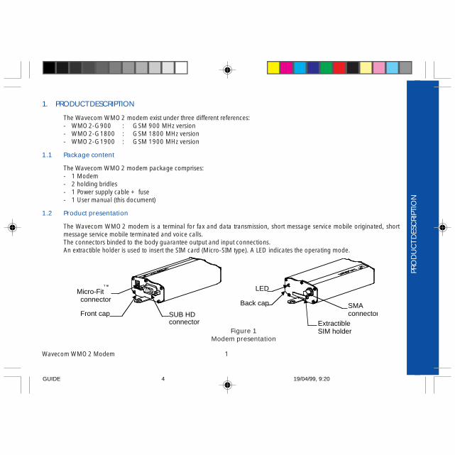
The Wavecom WMO2 modem is a terminal for fax and data transmission, short message service mobile originated, shortmessage service mobile terminated and voice calls.The connectors binded to the body guarantee output and input connections.An extractible holder is used to insert the SIM card (Micro-SIM type). A LED indicates the operating mode.
PRO
DU
CT
DES
CRI
PTIO
N
Wavecom WMO2 Modem 1
Micro-Fitconnector
T M
SUB HDconnector
Front cap
LED
ExtractibleSIM holder
SMAconnector
Back cap
Figure 1Modem presentation
GUIDE 19/04/99, 9:204
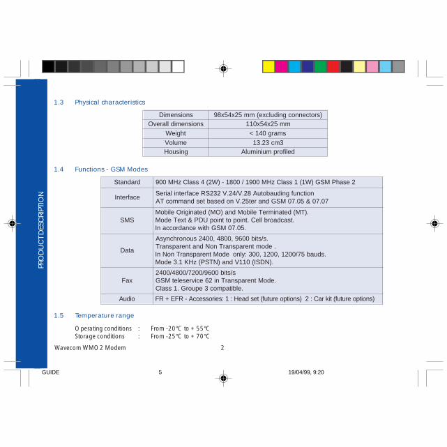
1.3 Physical characteristics
1.4 Functions - GSM Modes
1.5 Temperature range
Operating conditions : From -20°C to +55°CStorage conditions : From -25°C to +70°C
PRO
DU
CT
DES
CRI
PTIO
N
Wavecom WMO2 Modem 2
dradnatS 2esahPMSG)W1(1ssalCzHM0091/0081-)W2(4ssalCzHM009
ecafretnInoitcnufgniduabotuA82.V/42.V232SRecafretnilaireS
70.70&50.70MSGdnaret52.VnodesabtesdnammocTA
SMS.)TM(detanimreTeliboMdna)OM(detanigirOeliboM
.tsacdaorblleC.tniopottniopUDP&txeTedoM.50.70MSGhtiwecnadroccanI
ataD
.s/stib0069,0084,0042suonorhcnysA.edomtnerapsnarTnoNdnatnerapsnarT
.sduab57/0021,0021,003:ylnoedoMtnerapsnarTnoNnI.)NDSI(011Vdna)NTSP(zHK1.3edoM
xaFs/stib0069/0027/0084/0042
.edoMtnerapsnarTni26ecivreseletMSG.elbitapmoc3epuorG.1ssalC
oiduA )snoitpoerutuf(tikraC:2)snoitpoerutuf(tesdaeH:1:seirosseccA-RFE+RF
snoisnemiD )srotcennocgnidulcxe(mm52x45x89snoisnemidllarevO mm52x45x011
thgieW smarg041<emuloV 3mc32.31gnisuoH deliforpmuinimulA
GUIDE 19/04/99, 9:205

2 INSTALLATION/START-UP
2.1 Mounting the modem
For mounting the modem, bind to the body the holding bridles according to the schema below :
Figure 2Modem mounting
2.2 Installing the modem
To install the modem, plug the device on a DC power supply (for automotive application,connect the device on the permanent « + » and insert the SIM card in the holder).
Make sure that an antenna is connected.
In order to extract or to insert the Micro SIM card, it is necessary to press the SIM holder ejector with a sharp element (a penfor example).If this sequence is not respected, the SIM holder could be damaged.
INST
ALL
ATI
ON
/STA
RT-U
P
Wavecom WMO2 Modem 3
Note:- To be attached to a plain surface- Screw head max. height: 2mm
2 mmHolding bridles
2m
m
GUIDE 19/04/99, 9:216
2.3 Electrical characteristics
2.3.1 Switching the GSM modem on/off
The device is permanently powered (when connected to the power supply).
2.3.2 Voltage range
Voltage range : 5 to 32V DC (GSM 900) - 6 to 32V DC (GSM 1800/1900)GND : 0V
2.3.3 Overvoltage/undervoltage
Correct operation of the Wavecom WMO2 modem in communication mode is not guaranteed if input voltagefall below 5V (GSM 900) - 6V (GSM 1800/1900). The modem is protected against voltage over 32V.When input voltages exceed 32V, the supply voltage is disconnected in order to protect the electronic components from anovervoltage.
TWO CASES ARE POSSIBLE:
- IF THE OVERVOLTAGE IS CONTINUOUS, THE PROTECTION IS GUARANTEED BY THE FUSE.- IN THE CASE OF TRANSIENT PEAKS, THE MODEM GUARANTEES ITS OWN PROTECTION.
INST
ALL
ATI
ON
/STA
RT-U
P
Wavecom WMO2 Modem 4
GUIDE 19/04/99, 9:217

2.3.4 Power supply cable
A cable, included in the package shall be used for power supply connection.
The wires are marked as follows:
Cable : 1 wireAme : tinned copper 24x0.2 mmSection : 0.75 mm2
Figure 3Power supply cable IN
STA
LLA
TIO
N/S
TART
-UP
Wavecom WMO2 Modem 5
+-
Side view
Connector Molex Micro-Fit 3.0T M
Cables stripped over 200 mm,protected by their own sheath
Standard cable sheath
Stripped wire, tinned over 5 mm
- +
GUIDE 19/04/99, 9:218
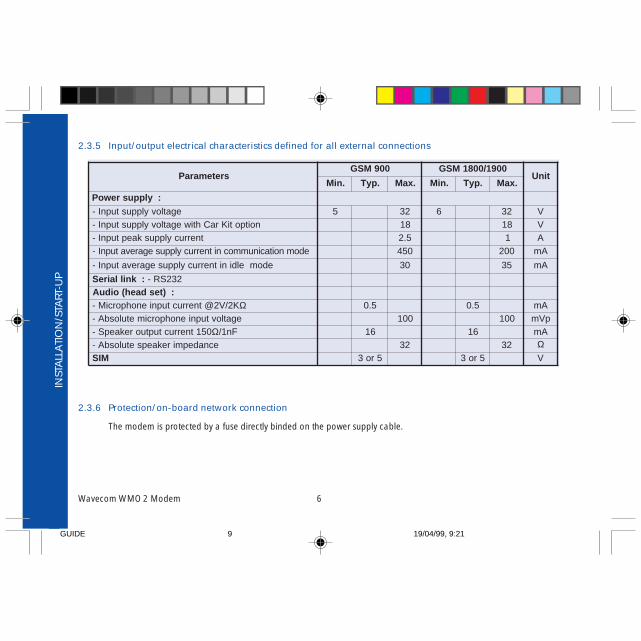
2.3.5 Input/output electrical characteristics defined for all external connections
2.3.6 Protection/on-board network connection
The modem is protected by a fuse directly binded on the power supply cable.
INST
ALL
ATI
ON
/STA
RT-U
P
Wavecom WMO2 Modem 6
sretemaraP009MSG 0091/0081MSG
tinU.niM .pyT .xaM .niM .pyT .xaM
:ylppusrewoPegatlovylppustupnI- 5 23 6 23 V
noitpotiKraChtiwegatlovylppustupnI- 81 81 VtnerrucylppuskaeptupnI- 5.2 1 A
- edomnoitacinummocnitnerrucylppusegarevatupnI 054 002 Am
edomeldinitnerrucylppusegarevatupnI- 03 53 Am
:knillaireS 232SR-:)tesdaeh(oiduA
K2/V2@tnerructupnienohporciM- Ω 5.0 5.0 AmegatlovtupnienohporcimetulosbA- 001 001 pVm
051tnerructuptuorekaepS- Ω Fn1/ 61 61 AmecnadepmirekaepsetulosbA- 23 23 Ω
MIS 5ro3 5ro3 V
GUIDE 19/04/99, 9:219

3. DESCRIPTION OF THE INTERFACES
The modem comprises several interfaces:- LED function indicating operating status- External antenna (via SMA)- Serial and control link (via 15 pins SUB D)- Power supply (via 4 pins Micro-FitTM)- SIM card holder
3.1 LED Function
- LED off Device switched off - Not ready- LED on Device switched on - Connecting to network- LED flashing slowly Device switched on - Idle mode- LED flashing rapidly Device switched on - Transmission mode
3.2 Connectors
DES
CRI
PTIO
N O
F TH
E IN
TERF
AC
ES
Wavecom WMO2 Modem 7
rotcennoC noitcnuF
AMS rotcennocannetnaFR
DBUSsnip51)ytisnedhgih(
knil232SRknilOIDUA
TOOBTESER
tiF-orciMsnip4 MT rotcennocylppusrewoP
rotcennoc»MIS« noitcennocdracMIS
GUIDE 19/04/99, 9:2110
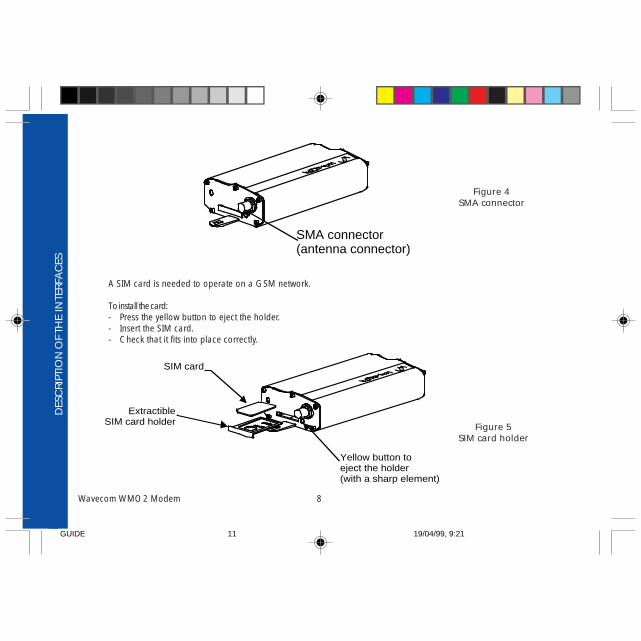
A SIM card is needed to operate on a GSM network.
To install the card:- Press the yellow button to eject the holder.- Insert the SIM card.- Check that it fits into place correctly.
DES
CRI
PTIO
N O
F TH
E IN
TERF
AC
ES
Wavecom WMO2 Modem 8
SMA connector(antenna connector)
ExtractibleSIM card holder
SIM card
Yellow button toeject the holder(with a sharp element)
Figure 5SIM card holder
Figure 4SMA connector
GUIDE 19/04/99, 9:2111
15
61015 11
DES
CRI
PTIO
N O
F TH
E IN
TERF
AC
ES
Wavecom WMO2 Modem 9
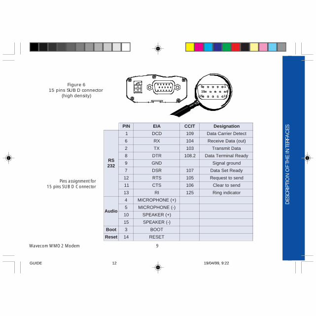
Pins assignment for15 pins SUB D Connector
Figure 615 pins SUB D connector
(high density)
NIP AIE TICC noitangiseD
SR232
1 DCD 901 tceteDreirraCataD
6 XR 401 )tuo(ataDevieceR
2 XT 301 ataDtimsnarT
8 RTD 2.801 ydaeRlanimreTataD
9 DNG dnuorglangiS
7 RSD 701 ydaeRteSataD
21 STR 501 dnesottseuqeR
11 STC 601 dnesotraelC
31 IR 521 rotacidnigniR
oiduA
4 )+(ENOHPORCIM
5 )-(ENOHPORCIM
01 )+(REKAEPS
51 )-(REKAEPS
tooB 3 TOOB
teseR 41 TESER
GUIDE 19/04/99, 9:2212
DES
CRI
PTIO
N O
F TH
E IN
TERF
AC
ES
Wavecom WMO2 Modem 10
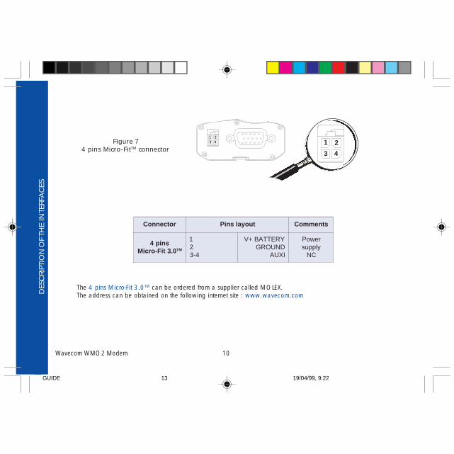
The 4 pins Micro-Fit 3.0TM can be ordered from a supplier called MOLEX.The address can be obtained on the following internet site : www.wavecom.com
Figure 74 pins Micro-FitTM connector
21
43
2143
rotcennoC tuoyalsniP stnemmoC
snip40.3tiF-orciM MT
12
4-3
YRETTAB+VDNUORGIXUA
rewoPylppus
CN
GUIDE 19/04/99, 9:2213

Wavecom WMO2 Modem 11
4. TECHNICAL DATA
TEC
HN
ICA
L DA
TA
noitpircseD sdnammocTA eludoM stnemmoC
orhcnyseludoMgnikcehc
?GERC+TA 1,>edom<=GERC krowtenehtnodezinorhcnysmedoM
2,>edom<=GERC tpmettanoitazinorhcnys-er,tsolnoitazinorhcnyS
0,>edom<=GERC tpmettanoitazinorhcnyskrowteN
nagnivieceRllacgnimocni
GNIR
ATA llacehtrewsnA
KO
llacaetaitinI
4321DTA ; llac»eciov«rofdneehtta»;«ehttegroft'noD
KO dehsilbatsenoitacinummoC
11:RORREEMC )edom1:EEMC+htiw(deretnetonedocNIP
3:RORREEMC dehsilbatseydaerlasinoitacinummocarodedeecxetidercCOA
naetaitinIllacycnegreme
211DTA ; llac»eciov«rofdneehtta»;«ehttegroft'noD
KO
ssolnoitacinummoC REIRRACON
pugnaHHTA
KO
edoCNIPretnE
4321=NIPC+TA
KO detpeccaedoCNIP
61:RORREEMC+ edoCNIPtcerrocnI
3:RORREEMC+ )edom1:EEMC+htiw(deretneydaerlaNIP
ehterotSP2Enisretemarap
W&TA
KO P2EniderotserasgnittesnoitarugifnocehT
GUIDE 19/04/99, 9:2214

Wavecom WMO2 Modem 12
5. TROUBLESHOOTING: Specific defaults possibly encountered
5.1 The modem does not answer through the serial link
A) Is the modem correctly powered on? If not, the correct power supply is 5 to 32V (GSM 900) - 6 to 32V (GSM 1800/1900).
B) Is the serial cable suitable and adjusted in the modem and PC sockets? A suitable cable must follow pin assignment described on figure 6. Check in particular, that Rx et Tx are properly connected.
C) Check that your communication program is properly configured: Modem factory setting for the character framing are:
Data Bits : 8 Parity : None Stop Bits : 1
The factory setting for baud rate is autobauding mode.
D) Does any other program interfere with your communication program (conflict on communication port access)? If yes, close any application likely to interfere (e.g. mouse or printer driver).TR
OU
BLES
HO
OTI
NG
GUIDE 19/04/99, 9:2215
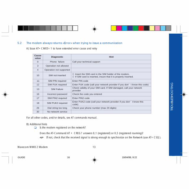
5.2 The modem always returns «Error» when trying to issue a communication
A) Issue AT+CMEE=1 to have extended error cause and retry
For all other codes, and/or details, see AT commands manual.
B) Additional hints Is the modem registered on the network?
Does the AT-Command AT + CREG? answers 0,1 (registered) or 0,5 (registered roaming)?
If not, check that the received signal is strong enough to synchronize on the Network (use AT+CSQ).
TRO
UBL
ESH
OO
TIN
G
Wavecom WMO2 Modem 13
esuaCeulav
citsongaiD tniH
0 eruliafenohP troppuslacinhcetruoyllaC
3 dewollatonnoitarepO
4 detroppustonnoitarepO
01 detresnitonMIS→ ,medomehtforedlohMISehtnidracMISehttresnI→ .detresniylreporpsititahterusni,detresnisidracMISfI
11 deriuqerNIPMIS edocNIPretnE
21 deriuqerKUPMIS )edocsihtwonkt’noduoyfiredivorpkrowtenruoyllac(edocKUPretnE
31 eruliaFMISkrowtenruoyllac,degamadMISfI.dracMISruoyfoytidilavkcehC
redivorp
61 drowssaptcerrocnI deretneuoyedocehtkcehC
71 deriuqer2NIPMIS edoc2NIPretnE
81 deriuqer2KUPMISsihtwonkt’noduoyfiredivorpkrowtenruoyllac(edoc2KUPretnE
)edoc
62 gnolootgnirtslaiD )stigid02xam(rebmunenohpruoykcehC
03 ecivreskrowtenoN
GUIDE 19/04/99, 9:2216

TRO
UBL
ESH
OO
TIN
G
Wavecom WMO2 Modem 14
Is the modem receiving an incoming call or already in communication? With some software versions, you must release any incoming or active call (with ATH) before being able
to make an outgoing call.
5.3 The modem always returns «No carrier» when trying to issue a communication
A) After a failed attempt (“no carrier”), issue AT+CEER to have extended error cause
For all other codes, and/or details, see AT commands manual.
eulavesuaC citsongaiD tniH
1 rebmunenohpdetacollanU
61 gniraelcllaclamroN
71 ysubresU
81 gnidnopserresuoN
91 rewsnaon,gnitrelaresU
12 detcejerllaC
22 degnahcrebmuN
13 deificepsnu,lamroN
05 debircsbustonytilicafdetseuqeRnoitpircsbusatad(noitpircsbusruoykcehC
)?elbaliava
86 xamMCAnahtretaergrolauqeMCA deripxedracMISdiap-erpruoyfotiderC
252 sllacgniogtuonognirabllaC
352 sllacgnimocninognirabllaC
,24,14,83,43,92,8,6,3,36,85,75,94,74,44,34
452,97,07,96,56sesuackrowteN
sliatedrehtrufroflaunamsdnammocTAeeSredivorpkrowtenllacro
GUIDE 19/04/99, 9:2217
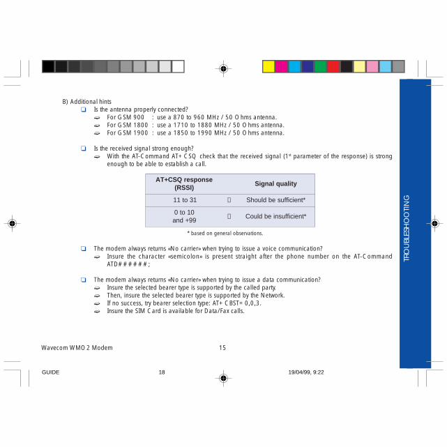
B) Additional hints Is the antenna properly connected?
For GSM 900 : use a 870 to 960 MHz / 50 Ohms antenna. For GSM 1800 : use a 1710 to 1880 MHz / 50 Ohms antenna. For GSM 1900 : use a 1850 to 1990 MHz / 50 Ohms antenna.
Is the received signal strong enough? With the AT-Command AT+CSQ check that the received signal (1st parameter of the response) is strong
enough to be able to establish a call.
* based on general observations.
The modem always returns «No carrier» when trying to issue a voice communication? Insure the character «semicolon» is present straight after the phone number on the AT-Command
ATD######;
The modem always returns «No carrier» when trying to issue a data communication? Insure the selected bearer type is supported by the called party. Then, insure the selected bearer type is supported by the Network. If no success, try bearer selection type: AT+CBST=0,0,3. Insure the SIM Card is available for Data/Fax calls.
TRO
UBL
ESH
OO
TIN
G
Wavecom WMO2 Modem 15
esnopserQSC+TA)ISSR(
ytilauqlangiS
13ot11 → *tneiciffusebdluohS
01ot099+dna → *tneiciffusniebdluoC
GUIDE 19/04/99, 9:2218

NO
TES
ON
SA
FETY
Wavecom WMO2 Modem 16
6. NOTES ON SAFETY
6.1 General Safety
It is important to follow any special regulations regarding the use of radio equipment due in particular to the possibility of radiofrequency, RF, interference. Please follow the safety advice given below carefully.
Switch OFF your GSM Modem when in an aircraft. The use of cellular telephones in an aircraft may endanger theoperation of the aircraft, disrupt the cellular network and is illegal. Failure to observe this instruction may lead to suspensionor denial of cellular telephone services to the offender, or legal action or both.
Switch OFF your GSM Modem when at a refueling point.
Switch OFF your GSM Modem in hospitals and any other place where medical equipment may be in use.
Respect restrictions on the use of radio equipment in fuel depots, chemical plants or where blasting operations are inprogress.
There may be a hazard associated with the operation of your GSM Modem close to in adequately protected personalmedical devices such as hearing aids and pacemakers. Consult the manufactures of the medical device to determine if it isadequately protected.
Operation of your GSM Modem close to other electronic equipment may also cause interference if the equipment isinadequately protected. Observe any warning signs and manufacturers recommendations.
GUIDE 19/04/99, 9:2219
6.2 Vehicle Safety
Do not use your GSM Modem while driving, unless equipped with a correctly installed vehicle kit allowing ‘Hands-Free’Operation.
Respect national regulations on the use of cellular telephones in vehicles. Road safety always comes first.
If incorrectly installed in a vehicle, the operation of GSM Modem telephone could interfere with the correct functioning ofvehicle electronics. To avoid such problems, ensure that the installation has been performed by a qualified personnel.Verification of the protection of vehicle electronics should form part of the installation.
The use of an alert device to operate a vehicle’s lights or horn on public roads is not permitted.
6.3 Car And Maintenance
Your GSM Modem is the product of advanced engineering, design and craftsmanship and should be treated with care. Thesuggestion below will help you to enjoy this product for many years.
Do not expose the GSM Modem to any extreme environment where the temperature or humidity is high.
Do not attempt to disassemble the GSM Modem. There are no user serviceable parts inside.
Do not expose the GSM Modem to water, rain or spilt beverages, It is not waterproof.
Do not abuse your GSM Modem by dropping, knocking, or violent shaking. Rough handling can damage it.
Do not place the GSM Modem alongside computer discs, credit or travel cards or other magnetic media. The informationcontained on discs or cards may be affected by the phone.
NO
TES
ON
SA
FETY
Wavecom WMO2 Modem 17
GUIDE 19/04/99, 9:2220
The use of third party equipment or accessories, not made or authorized by Wavecom may invalidate the warranty of GSMModem.
Do contact an authorized Service Center in the unlikely event of a fault.
6.4 Your Responsibility
This GSM Modem is under your responsibility. Please treat it with care respecting all local regulations. It is not a toy thereforekeep it in a safe place at all times and out of the reach of children.Try to remember your Unlock and PIN codes. Become familiar with and use the security features to block unauthorized use andtheft.
NO
TES
ON
SA
FETY
Wavecom WMO2 Modem 18
GUIDE 19/04/99, 9:2221

7. GENERAL INFORMATIONS
GSM reference documents : GSM 03.40, GSM 03.45, GSM 04.11,GSM 04.21, GSM 05.08, GSM 07.01,GSM 07.02, GSM 07.05, GSM 07.07.
ETSI contact : ETSI SecretariatF-06921 Sophia Antipolis Cedex, Francee-mail : [email protected]
Service : The AT commands manual is avalable on Wavecom web site:http://www.wavecom.com
DisclaimerModem and GSM-unit specifications and manuals are subject to change without notice. Wavecom assumes no liability fordamage incurred directly or indirectly from errors, omissions or discrepancies between the modem or GSM-unit and theirmanuals.
TrademarksSome mentioned products are registred trademarks of them respective companies.
CopyrightThis manual is copyrighted by Wavecom with all rights reserved. No part of this manual may be reproduced in any form withoutthe prior written permission of Wavecom.No patent liability is assumed with respect to the use of the information contained herein.
GEN
ERA
L IN
FORM
ATI
ON
S
Wavecom WMO2 Modem 19
GUIDE 19/04/99, 9:2222

WAVECOM S.A. - 39 rue du Gouverneur Gal. Eboué, F-92130 Issy-les-Moulineaux - FranceTel: +33 1 46 29 08 00 - Fax: +33 1 46 29 08 08
WAVECOM Inc. - 5405 Morehouse Drive, Suite 330 - San Diego, CA 92121 - USATel: +1 619 450 1778 - Fax: +1 619 450 1636
WAVECOM Asia Pacific Ltd. - 2 nd floor, Shui On Center, 6/8 Harbour Road - Hong KongTel: +852 2824 8973 - Fax: +852 2824 8929
GUIDE 19/04/99, 9:2323


![CODAN HF Data Decoder - WAVECOM, the reference in data ... · Wavecom decoders (HF Modes → PSK & ... Internet https: ... HF Data Modem î í î User Guide [] Internet Reference](https://img.pdfslide.us/doc/110x75/5d33b9fb88c993d91a8d8284/codan-hf-data-decoder-wavecom-the-reference-in-data-wavecom-decoders.jpg)