Embed Size (px)
Citation preview
Operating Manual OM WMC
Group: Chiller Part Number: 330599802 Effective: December 2004 Supersedes: New
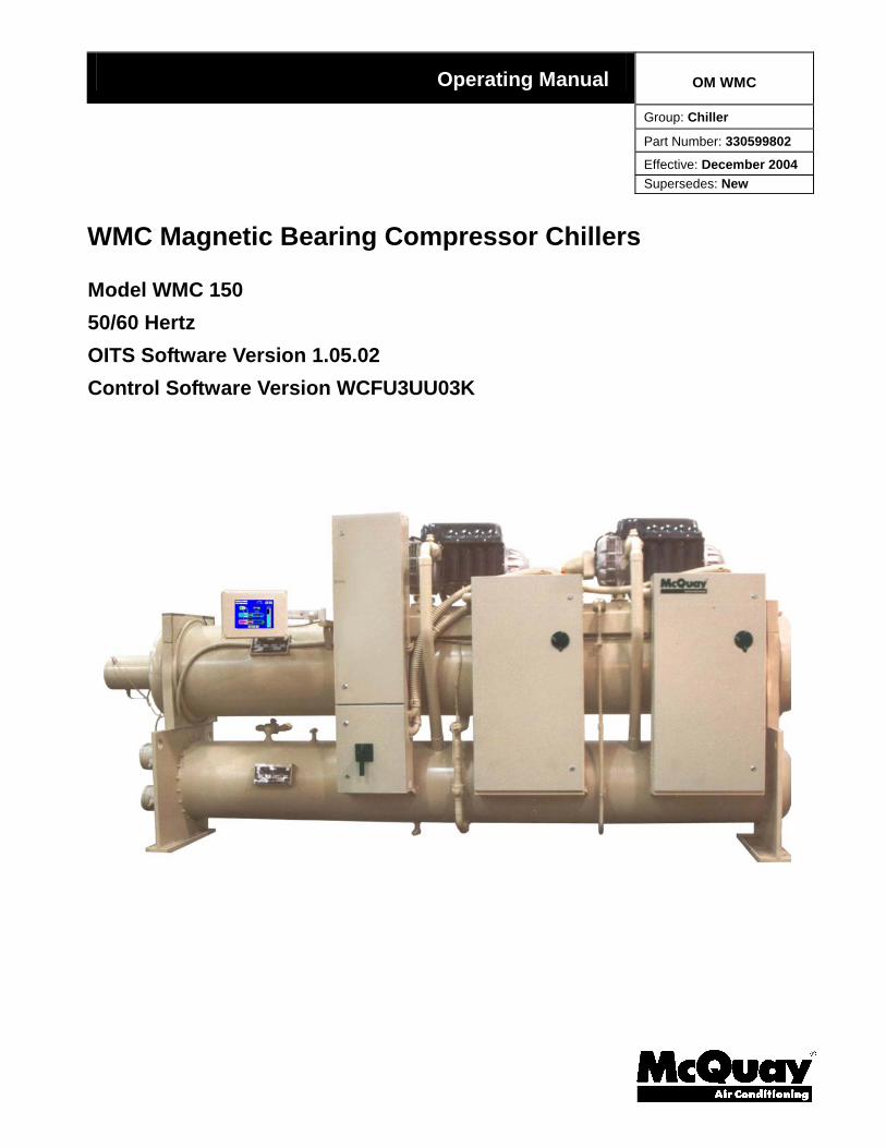
WMC Magnetic Bearing Compressor Chillers
Model WMC 150 50/60 Hertz OITS Software Version 1.05.02 Control Software Version WCFU3UU03K
2 OM WMC
Table of Contents Introduction............................................. 3
Features of the Control Panel ................ 4
Definitions................................................ 5
General Description................................ 8
Control Panel......................................... 10
Use with On-Site Generators ................11
Sequence of Operation ......................... 12
Multi-Chiller Setup............................... 13 Operating Limits: ..............................................15
Operating the Control System............. 16 Interface Panel On/Off ......................................16 Start/Stop Unit...................................................16 Change Setpoints...............................................16 Alarms...............................................................16 Component Failure............................................17
Component Description........................ 17 Operator Interface Touch Screen.......................17 Unit/Compressor Controller Description ..........17 Navigating.........................................................18
Unit Controller...................................... 21 Unit Controller Setpoints ..................................21 Faults, Problems, Warnings...............................23
Unit Controller Functions................................. 24 Compressor Controller......................... 25
Compressor Controller Setpoints ..................... 26 Compressor Faults, Problems, Warnings .......... 27 Compressor Controller Functions..................... 28
Compressor On-Board Controllers............................................. 32
Interface Touch Screen......................... 34 Navigation ........................................................ 34 Screen Descriptions.......................................... 36 VIEW Screens .................................................. 36 SET Screens ..................................................... 42 SERVICE Screen.............................................. 55 HISTORY Screens............................................ 56 Download Data................................................. 57 ACTIVE ALARM Screen ................................ 58 Blank/Locked-up Screen .................................. 59
Unit Controller Menu Screens............. 60 Menu Matrix..................................................... 61
Compressor Controller Menu Screens ................................................... 77
Menu Matrix..................................................... 77 BAS Interface........................................ 79
Manufactured in an ISO Certified Facility
©2004 McQuay International Illustrations and information cover McQuay International products at the time of publication and we reserve the right to make changes in design and
construction at anytime without notice.
®™ The following are trademarks or registered trademarks of their respective companies: BACnet from ASHRAE; Modbus from Gould, Inc; LONMARK and LONWORKS from Echelon Corporation; and MicroTech II from McQuay International.
Controllers are LONMARK certified with an optional LONWORKS
communication module.
OM WMC 3
Introduction
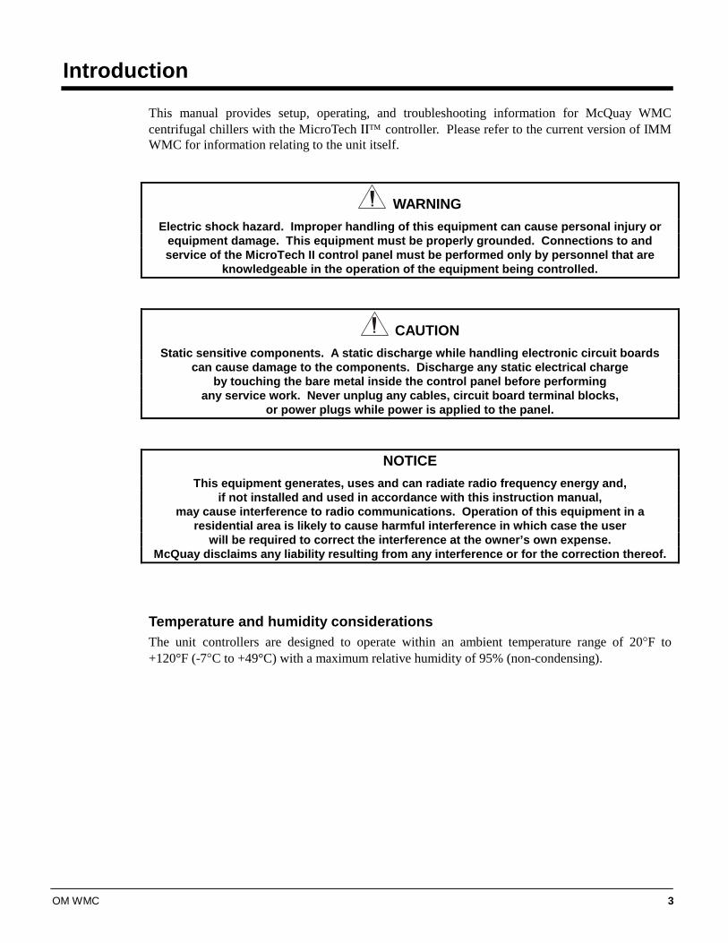
This manual provides setup, operating, and troubleshooting information for McQuay WMC centrifugal chillers with the MicroTech ΙΙ™ controller. Please refer to the current version of IMM WMC for information relating to the unit itself.
WARNING
Electric shock hazard. Improper handling of this equipment can cause personal injury or equipment damage. This equipment must be properly grounded. Connections to and service of the MicroTech II control panel must be performed only by personnel that are
knowledgeable in the operation of the equipment being controlled.
CAUTION
Static sensitive components. A static discharge while handling electronic circuit boards can cause damage to the components. Discharge any static electrical charge
by touching the bare metal inside the control panel before performing any service work. Never unplug any cables, circuit board terminal blocks,
or power plugs while power is applied to the panel.
NOTICE This equipment generates, uses and can radiate radio frequency energy and,
if not installed and used in accordance with this instruction manual, may cause interference to radio communications. Operation of this equipment in a
residential area is likely to cause harmful interference in which case the user will be required to correct the interference at the owner’s own expense.
McQuay disclaims any liability resulting from any interference or for the correction thereof.
Temperature and humidity considerations The unit controllers are designed to operate within an ambient temperature range of 20°F to +120°F (-7°C to +49°C) with a maximum relative humidity of 95% (non-condensing).
4 OM WMC
Features of the Control Panel
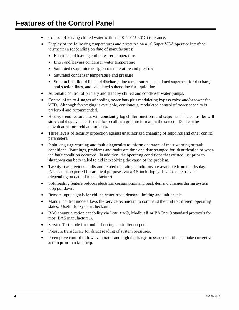
• Control of leaving chilled water within a ±0.5°F (±0.3°C) tolerance. • Display of the following temperatures and pressures on a 10 Super VGA operator interface
touchscreen (depending on date of manufacture): • Entering and leaving chilled water temperature • Enter and leaving condenser water temperature • Saturated evaporator refrigerant temperature and pressure • Saturated condenser temperature and pressure • Suction line, liquid line and discharge line temperatures, calculated superheat for discharge
and suction lines, and calculated subcooling for liquid line • Automatic control of primary and standby chilled and condenser water pumps. • Control of up to 4 stages of cooling tower fans plus modulating bypass valve and/or tower fan
VFD. Although fan staging is available, continuous, modulated control of tower capacity is preferred and recommended.
• History trend feature that will constantly log chiller functions and setpoints. The controller will store and display specific data for recall in a graphic format on the screen. Data can be downloaded for archival purposes.
• Three levels of security protection against unauthorized changing of setpoints and other control parameters.
• Plain language warning and fault diagnostics to inform operators of most warning or fault conditions. Warnings, problems and faults are time and date stamped for identification of when the fault condition occurred. In addition, the operating conditions that existed just prior to shutdown can be recalled to aid in resolving the cause of the problem.
• Twenty-five previous faults and related operating conditions are available from the display. Data can be exported for archival purposes via a 3.5-inch floppy drive or other device (depending on date of manuafacture).
• Soft loading feature reduces electrical consumption and peak demand charges during system loop pulldown.
• Remote input signals for chilled water reset, demand limiting and unit enable. • Manual control mode allows the service technician to command the unit to different operating
states. Useful for system checkout. • BAS communication capability via LONTALK®, Modbus® or BACnet® standard protocols for
most BAS manufacturers. • Service Test mode for troubleshooting controller outputs. • Pressure transducers for direct reading of system pressures. • Preemptive control of low evaporator and high discharge pressure conditions to take corrective
action prior to a fault trip.
OM WMC 5
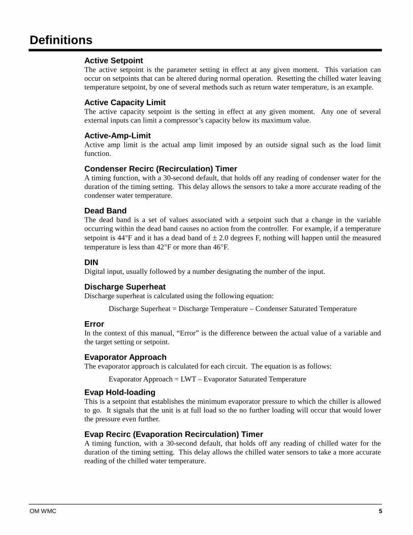
Definitions Active Setpoint The active setpoint is the parameter setting in effect at any given moment. This variation can occur on setpoints that can be altered during normal operation. Resetting the chilled water leaving temperature setpoint, by one of several methods such as return water temperature, is an example.
Active Capacity Limit The active capacity setpoint is the setting in effect at any given moment. Any one of several external inputs can limit a compressor’s capacity below its maximum value.
Active-Amp-Limit Active amp limit is the actual amp limit imposed by an outside signal such as the load limit function.
Condenser Recirc (Recirculation) Timer A timing function, with a 30-second default, that holds off any reading of condenser water for the duration of the timing setting. This delay allows the sensors to take a more accurate reading of the condenser water temperature.
Dead Band The dead band is a set of values associated with a setpoint such that a change in the variable occurring within the dead band causes no action from the controller. For example, if a temperature setpoint is 44°F and it has a dead band of ± 2.0 degrees F, nothing will happen until the measured temperature is less than 42°F or more than 46°F.
DIN Digital input, usually followed by a number designating the number of the input.
Discharge Superheat Discharge superheat is calculated using the following equation:
Discharge Superheat = Discharge Temperature – Condenser Saturated Temperature
Error In the context of this manual, “Error” is the difference between the actual value of a variable and the target setting or setpoint.
Evaporator Approach The evaporator approach is calculated for each circuit. The equation is as follows:
Evaporator Approach = LWT – Evaporator Saturated Temperature
Evap Hold-loading This is a setpoint that establishes the minimum evaporator pressure to which the chiller is allowed to go. It signals that the unit is at full load so the no further loading will occur that would lower the pressure even further.
Evap Recirc (Evaporation Recirculation) Timer A timing function, with a 30-second default, that holds off any reading of chilled water for the duration of the timing setting. This delay allows the chilled water sensors to take a more accurate reading of the chilled water temperature.
6 OM WMC
EXV Electronic expansion valve, used to control the flow of refrigerant to the evaporator, controlled by the circuit microprocessor.
Load Limit An external signal from the keypad, the BAS, or a 4-20 ma signal that limits the compressor loading to a designated percent of full load. Used to limit unit power input.
Load Balance Load balance is a technique that equally distributes the total unit load between two or more running compressors.
Low Pressure Hold (Inhibit) Setpoint The psi evaporator pressure setting at which the controller will not allow further compressor loading. “Hold” and “Inhibit” are used interchangeably.
Low Pressure Unload Setpoint The psi evaporator pressure setting at which the controller will unload the compressor in an effort to maintain the minimum setting.
LWT Evaporator leaving water temperature. The “water” is any fluid used in the chiller circuit.
LWT Error Error in the controller context is the difference between the value of a variable and the setpoint. For example, if the LWT setpoint is 44°F and the actual temperature of the water at a given moment is 46°F, the LWT error is +2 degrees.
LWT Slope The LWT slope is an indication of the trend of the chilled water temperature. It is calculated by taking readings of the temperature every few seconds and subtracting them from the previous value, over a rolling one-minute interval.
ms Milli-second
Maximum Saturated Condenser Temperature The maximum saturated condenser temperature allowed is calculated based on the compressor operational envelope.
OAT Outside ambient air temperature
Offset Offset is the difference between the actual value of a variable (such as temperature or pressure) and the reading shown on the microprocessor as a result of the sensor signal.
OITS Operator Interface Touch Screen, one screen per unit provides operating data visually and accommodates setpoint entry.
pLAN Peco Local Area Network is the proprietary name of the network connecting the control elements.
Refrigerant Saturated Temperature Refrigerant saturated temperature is calculated from the pressure sensor readings. The pressure is fitted to an R-134a temperature/pressure curve to determine the saturated temperature.
OM WMC 7
Soft Load Soft Load is a control sub-routine that allows the chiller to load up gradually. It requires setpoint inputs of selecting it by Yes or No inputs, by selecting the percent load to start ramping up, and by selecting the time to ramp up to full load (up to 60 minutes).
SP Setpoint
Suction Superheat Suction superheat is calculated for each circuit using the following equation:
Suction Superheat = Suction Temperature – Evaporator Saturated Temperature
Stageup/Stagedown Delta-T Staging is the act of starting or stopping a compressor or fan when another is still operating. Startup and Stop is the act of starting the first compressor or fan and stopping the last compressor or fan. The Delta-T is the “dead band” on either side the setpoint in which no action is taken. Stage Up Delay The time delay from the start of the first compressor to the start of the second.
Startup Delta-T Number of degrees above the LWT setpoint required to start the first compressor.
Stop Delta-T Number of degrees below the LWT setpoint required for the last compressor to stop.
VDC Volts, Direct current, sometimes noted as vdc.
VFD Variable Frequency Drive, a device located on the compressor, used to vary the compressor speed.
8 OM WMC
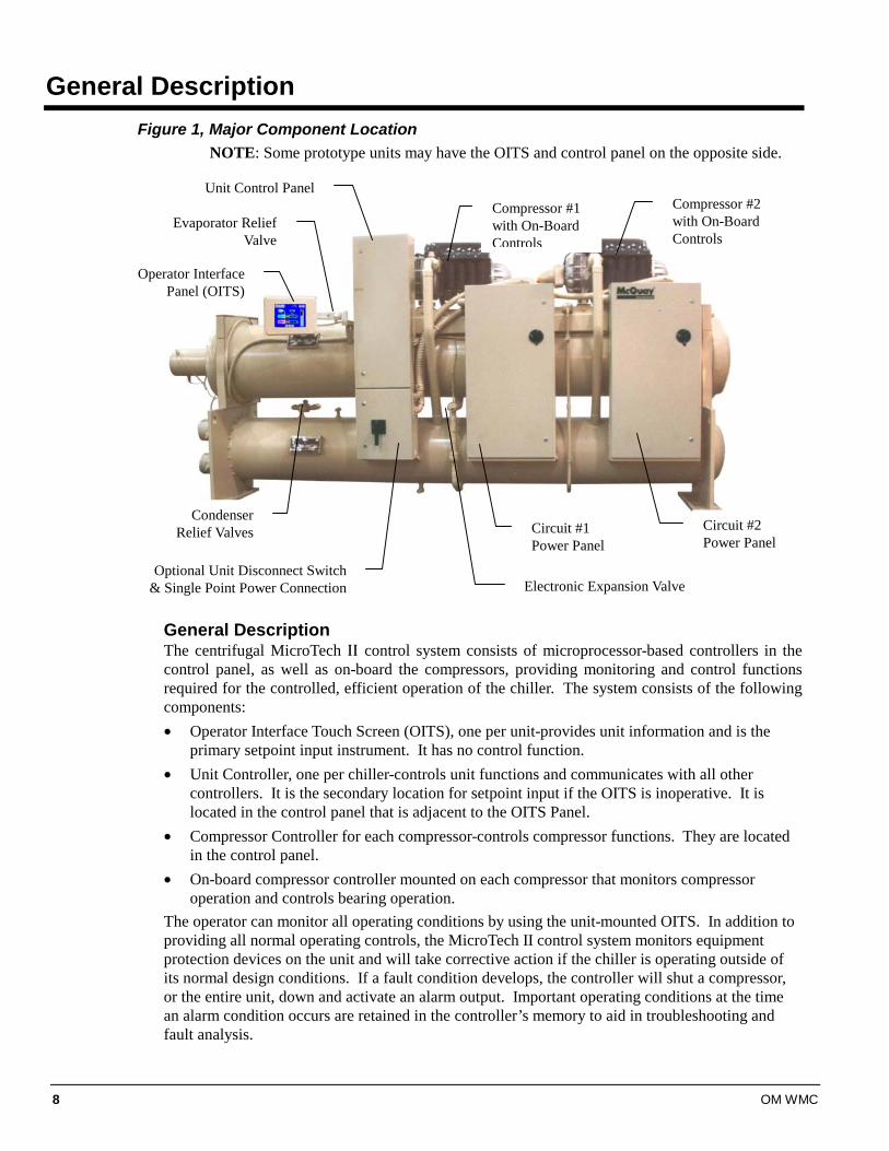
General Description Figure 1, Major Component Location
NOTE: Some prototype units may have the OITS and control panel on the opposite side.
General Description The centrifugal MicroTech ΙΙ control system consists of microprocessor-based controllers in the control panel, as well as on-board the compressors, providing monitoring and control functions required for the controlled, efficient operation of the chiller. The system consists of the following components: • Operator Interface Touch Screen (OITS), one per unit-provides unit information and is the
primary setpoint input instrument. It has no control function. • Unit Controller, one per chiller-controls unit functions and communicates with all other
controllers. It is the secondary location for setpoint input if the OITS is inoperative. It is located in the control panel that is adjacent to the OITS Panel.
• Compressor Controller for each compressor-controls compressor functions. They are located in the control panel.
• On-board compressor controller mounted on each compressor that monitors compressor operation and controls bearing operation.
The operator can monitor all operating conditions by using the unit-mounted OITS. In addition to providing all normal operating controls, the MicroTech II control system monitors equipment protection devices on the unit and will take corrective action if the chiller is operating outside of its normal design conditions. If a fault condition develops, the controller will shut a compressor, or the entire unit, down and activate an alarm output. Important operating conditions at the time an alarm condition occurs are retained in the controller’s memory to aid in troubleshooting and fault analysis.
Circuit #2 Power Panel
Compressor #2 with On-Board Controls
Compressor #1 with On-Board Controls
Circuit #1 Power Panel
Unit Control Panel
Operator Interface Panel (OITS)
Optional Unit Disconnect Switch & Single Point Power Connection Electronic Expansion Valve
Condenser Relief Valves
Evaporator Relief Valve
OM WMC 9
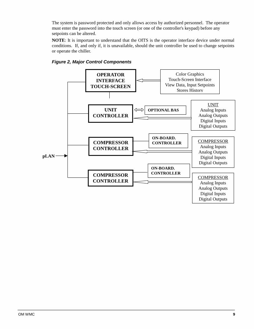
The system is password protected and only allows access by authorized personnel. The operator must enter the password into the touch screen (or one of the controller's keypad) before any setpoints can be altered. NOTE: It is important to understand that the OITS is the operator interface device under normal conditions. If, and only if, it is unavailable, should the unit controller be used to change setpoints or operate the chiller. Figure 2, Major Control Components
OPERATOR INTERFACE
TOUCH-SCREEN
UNIT CONTROLLER
COMPRESSOR CONTROLLER
COMPRESSOR CONTROLLER
Color Graphics Touch-Screen Interface
View Data, Input SetpointsStores History
UNIT Analog Inputs
Analog Outputs Digital Inputs
Digital Outputs
COMPRESSOR Analog Inputs
Analog Outputs Digital Inputs
Digital Outputs
OPTIONAL BAS
ON-BOARD. CONTROLLER
ON-BOARD. CONTROLLER
COMPRESSOR Analog Inputs
Analog Outputs Digital Inputs
Digital Outputs
pLAN
10 OM WMC
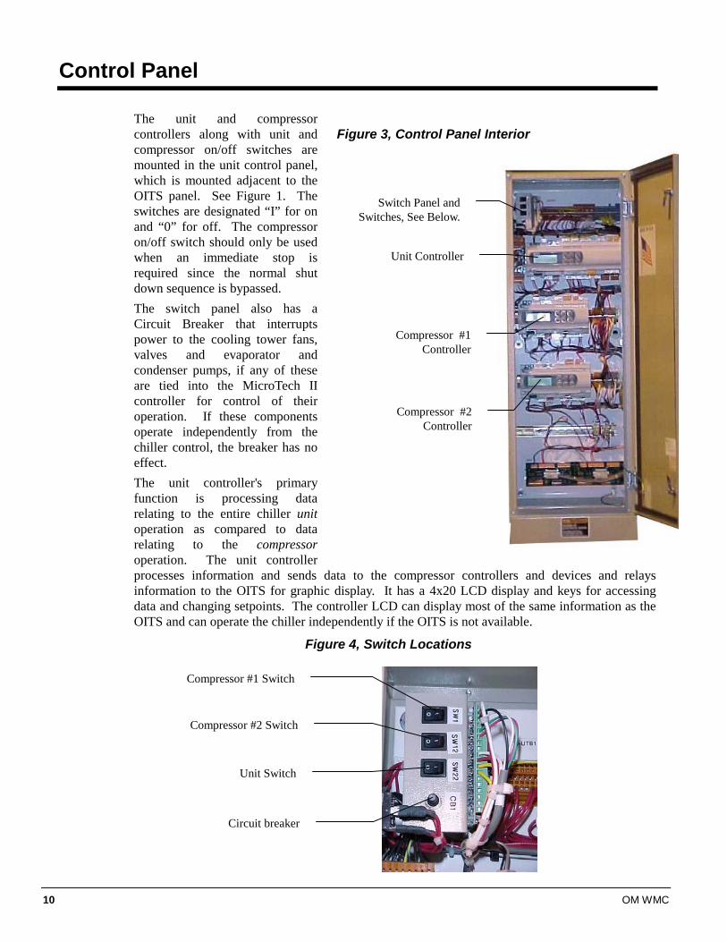
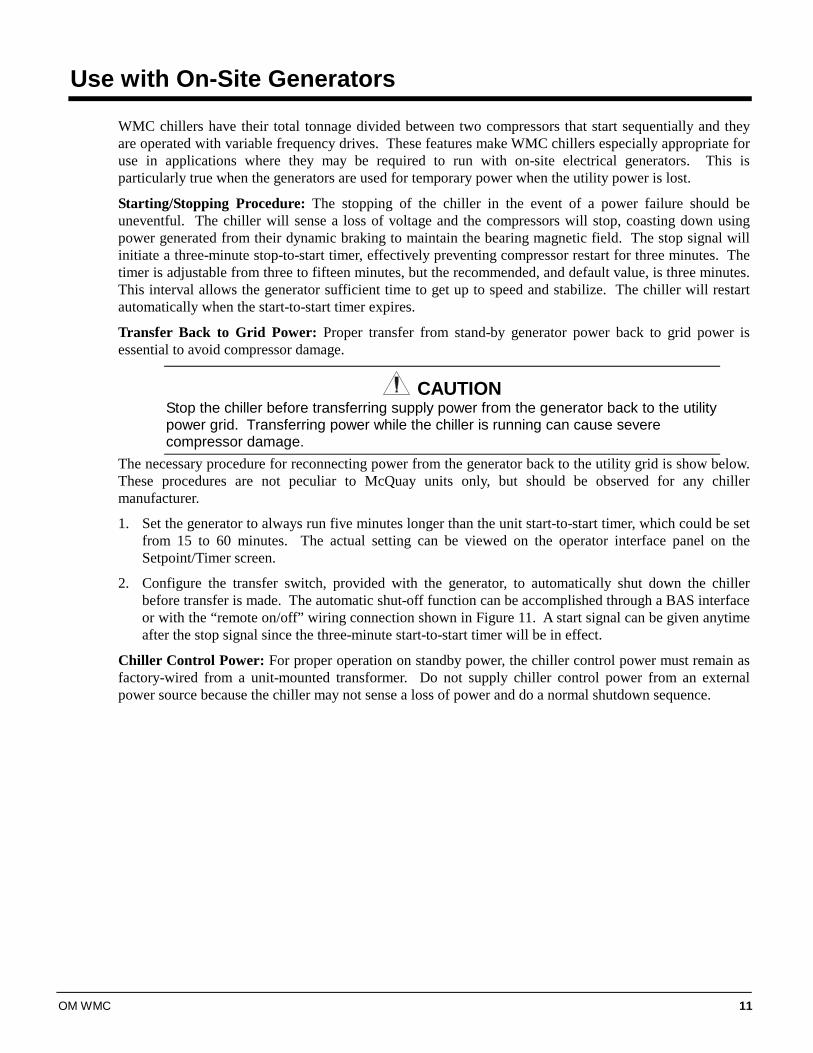
Control Panel The unit and compressor controllers along with unit and compressor on/off switches are mounted in the unit control panel, which is mounted adjacent to the OITS panel. See Figure 1. The switches are designated “I” for on and “0” for off. The compressor on/off switch should only be used when an immediate stop is required since the normal shut down sequence is bypassed. The switch panel also has a Circuit Breaker that interrupts power to the cooling tower fans, valves and evaporator and condenser pumps, if any of these are tied into the MicroTech II controller for control of their operation. If these components operate independently from the chiller control, the breaker has no effect. The unit controller's primary function is processing data relating to the entire chiller unit operation as compared to data relating to the compressor operation. The unit controller processes information and sends data to the compressor controllers and devices and relays information to the OITS for graphic display. It has a 4x20 LCD display and keys for accessing data and changing setpoints. The controller LCD can display most of the same information as the OITS and can operate the chiller independently if the OITS is not available.
Figure 4, Switch Locations
Figure 3, Control Panel Interior
Switch Panel and Switches, See Below.
Unit Controller
Compressor #1 Controller
Compressor #2 Controller
Compressor #1 Switch
Compressor #2 Switch
Unit Switch
Circuit breaker
OM WMC 11
Use with On-Site Generators
WMC chillers have their total tonnage divided between two compressors that start sequentially and they are operated with variable frequency drives. These features make WMC chillers especially appropriate for use in applications where they may be required to run with on-site electrical generators. This is particularly true when the generators are used for temporary power when the utility power is lost.
Starting/Stopping Procedure: The stopping of the chiller in the event of a power failure should be uneventful. The chiller will sense a loss of voltage and the compressors will stop, coasting down using power generated from their dynamic braking to maintain the bearing magnetic field. The stop signal will initiate a three-minute stop-to-start timer, effectively preventing compressor restart for three minutes. The timer is adjustable from three to fifteen minutes, but the recommended, and default value, is three minutes. This interval allows the generator sufficient time to get up to speed and stabilize. The chiller will restart automatically when the start-to-start timer expires.
Transfer Back to Grid Power: Proper transfer from stand-by generator power back to grid power is essential to avoid compressor damage.
CAUTION Stop the chiller before transferring supply power from the generator back to the utility power grid. Transferring power while the chiller is running can cause severe compressor damage.
The necessary procedure for reconnecting power from the generator back to the utility grid is show below. These procedures are not peculiar to McQuay units only, but should be observed for any chiller manufacturer.
1. Set the generator to always run five minutes longer than the unit start-to-start timer, which could be set from 15 to 60 minutes. The actual setting can be viewed on the operator interface panel on the Setpoint/Timer screen.
2. Configure the transfer switch, provided with the generator, to automatically shut down the chiller before transfer is made. The automatic shut-off function can be accomplished through a BAS interface or with the “remote on/off” wiring connection shown in Figure 11. A start signal can be given anytime after the stop signal since the three-minute start-to-start timer will be in effect.
Chiller Control Power: For proper operation on standby power, the chiller control power must remain as factory-wired from a unit-mounted transformer. Do not supply chiller control power from an external power source because the chiller may not sense a loss of power and do a normal shutdown sequence.
12 OM WMC
Sequence of Operation
Start-up of WMC Compressors:
“Next On” status If none of the “OFF” conditions are true, then all the MicroTech II compressor controls in a network of up to 2 units (four compressors) will pole the status of each to determine the one having “Next On” status, which is usually the compressor with the least starts. This takes about one minute.
Evap (Evaporator) Pump Start Once this is determined, the unit controller of the chiller with the ‘Next On’ compressor (when there are two chillers) will start the evaporator pump and determine if there is load based on the water temperature. This is determined if the leaving evaporator water is above the ‘LWT Setpoint’ plus ‘Startup Delta T’. If there is no load, based on the temperature, the unit is in the state of ‘Awaiting Load’.
Interlock On If there is load, the unit waits for the Evaporator Recirculation Timer period (default value of 30 seconds) and starts the Interlock Timer for 10 sec.
Cond (Condenser) Pump Start After Interlock is confirmed, the controller starts the Condenser Pump and checks for condenser flow before starting the first compressor.
Compressor Start Starting the compressor is accomplished by setting the Demand to 25% of the MAX KW setpoint. When the actual RPM of the compressor exceeds 350 RPM, the demand setting is allowed to be governed by the normal control logic.
Compressor Run The compressor that is running will signal all other compressors when it reaches full load. Full load status is determined when any one of the following tests is true:
1. Percent RLA exceeds 100% or the Active-Amp-Limit from an external-limiting source.
2. Evap Saturation pressure drops below the Evap Hold-Loading pressure setpoint.
3. Actual compressor RPM exceeds 97% of Max RPM limit from compressor.
Lag Compressor Staging The ‘Next On’ compressor, will initiate the following staging sequence when it receives a Full Load indication from the Lead compressor, or all other running compressors in the case of a four compressor (two units) setup.
OM WMC 13
The lag compressor will start (Demand set to 25% of Max KW setpoint). When the actual RPM exceeds 350 RPM, the lead compressor will unload to 25% of the MAX KW setpoint. The lead compressor will maintain this demand setting for a time period set by the Step-Down timer (found in Set COMP1 SPs (8) ). When the Step–Down timer expires, both compressors should be nearly matched in capacity and can began amp balancing to share the load equally.
Note: If the “Next On” compressor is on another chiller, the controller will start that chiller’s evaporator and condenser pumps, if they are separate from the lead unit’s pumps. Only compressors on the same unit will unload the lead compressor before starting the lag compressor.
Unloading compressors: The setpoint of ‘Nominal Capacity’ is used for defining the point to unload a compressor on a single or two-chiller system. With each compressor having its ‘Nominal Capacity’ defined, then the network, which is load balanced, continues to unload at 0.2 tenths or more below setpoint. Each compressor keeps computing the spare capacity of the network. When the designated ‘Next Off’ sees enough spare capacity, it will turn off. Then similarly, in about 40 seconds, a new compressor will be designated as the ‘Next Off’ and the spare capacity will continue to be calculated between the remaining compressors. Compressors continue to unload and stage off until there is only one compressor running. It will shut off when the water temperature reaches the LWT Setpoint minus the Shutdown Delta T.
Multi-Chiller Setup
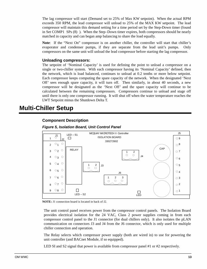
Component Description Figure 5, Isolation Board, Unit Control Panel
J1J2
J3
J6
J4
J5ISOLATION BOARD
RELAY
330272602
CAP
MCQUAY MICROTECH II Controller
1 2 3
1 2
1 2
LED – S2
LED – S1
LED
1
2
3
4
5
6
7
8
9
1
2
3
4
5
6
7
8 1
2
3
4
5
6
7
8
9
NOTE: J1 connection board is located in back of J2. The unit control panel receives power from the compressor control panels. The Isolation Board provides electrical isolation for the 24 VAC, Class 2 power supplies coming in from each compressor control panel to the J1 connector (for dual chillers only). It also isolates the pLAN communication on connectors J3 and J4 from the J6 connector, which is only used for multiple chiller connection and operation.
The Relay selects which compressor power supply (both are wired in) to use for powering the unit controller (and BACnet Module, if so equipped).
LED SI and S2 signal that power is available from compressor panel #1 or #2 respectively.
14 OM WMC
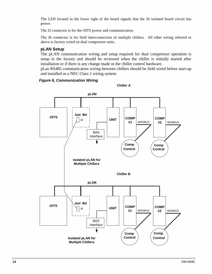
The LED located in the lower right of the board signals that the J6 isolated board circuit has power.
The J2 connector is for the OITS power and communication.
The J6 connector is for field interconnection of multiple chillers. All other wiring referred to above is factory wired on dual compressor units.
pLAN Setup The pLAN communication wiring and setup required for dual compressor operation is setup in the factory and should be reviewed when the chiller is initially started after installation or if there is any change made in the chiller control hardware. pLan RS485 communication wiring between chillers should be field wired before start-up and installed as a NEC Class 1 wiring system.
Figure 6, Communication Wiring
pLAN
Isol BdOITS
UNIT COMP#1
CompControl
MODBUS
BASInterface
COMP#2
CompControl
MODBUS
Chiller A
pLAN
Isol BdOITS
UNIT COMP#1
CompControl
MODBUS
BASInterface
COMP#2
CompControl
MODBUS
Chiller B
J6
J6
Isolated pLAN forMultiple Chillers
Isolated pLAN forMultiple Chillers
OM WMC 15
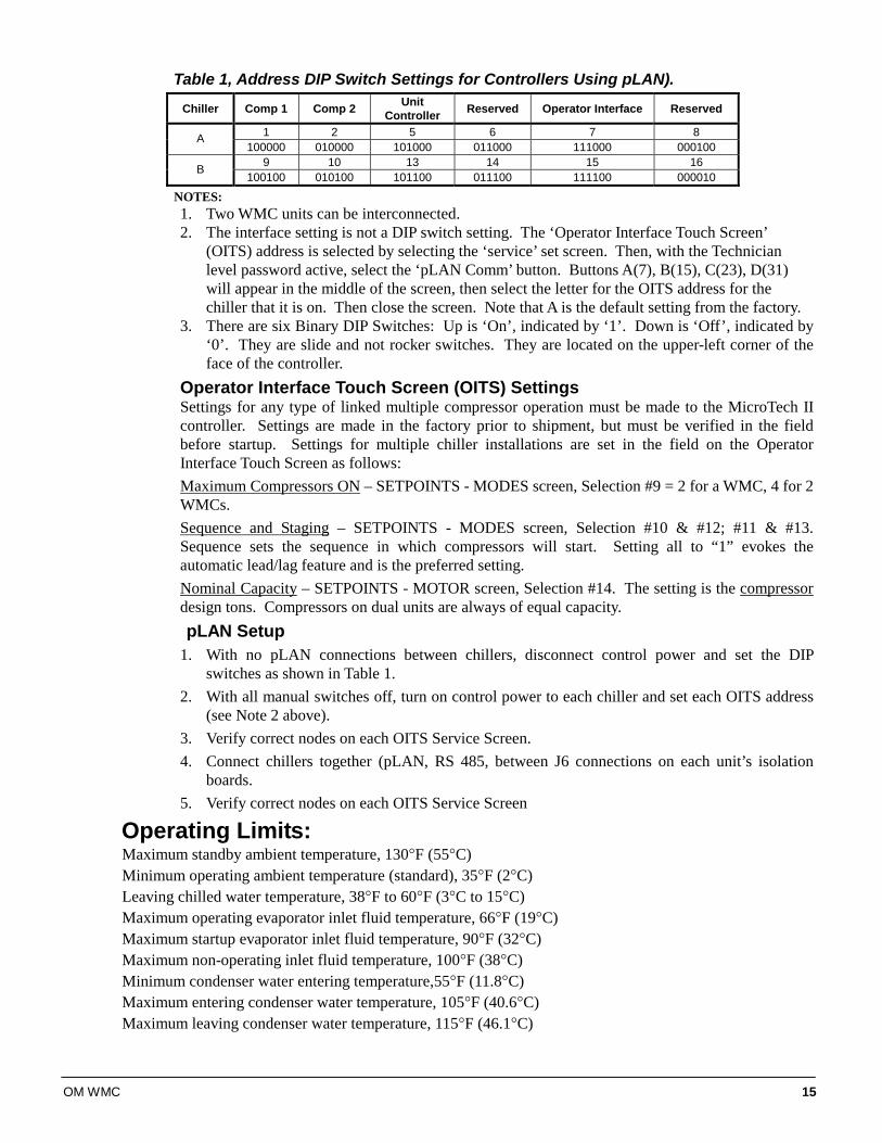
Table 1, Address DIP Switch Settings for Controllers Using pLAN).
Chiller Comp 1 Comp 2 Unit Controller Reserved Operator Interface Reserved
1 2 5 6 7 8 A 100000 010000 101000 011000 111000 000100
9 10 13 14 15 16 B 100100 010100 101100 011100 111100 000010
NOTES: 1. Two WMC units can be interconnected. 2. The interface setting is not a DIP switch setting. The ‘Operator Interface Touch Screen’
(OITS) address is selected by selecting the ‘service’ set screen. Then, with the Technician level password active, select the ‘pLAN Comm’ button. Buttons A(7), B(15), C(23), D(31) will appear in the middle of the screen, then select the letter for the OITS address for the chiller that it is on. Then close the screen. Note that A is the default setting from the factory.
3. There are six Binary DIP Switches: Up is ‘On’, indicated by ‘1’. Down is ‘Off’, indicated by ‘0’. They are slide and not rocker switches. They are located on the upper-left corner of the face of the controller.
Operator Interface Touch Screen (OITS) Settings Settings for any type of linked multiple compressor operation must be made to the MicroTech II controller. Settings are made in the factory prior to shipment, but must be verified in the field before startup. Settings for multiple chiller installations are set in the field on the Operator Interface Touch Screen as follows: Maximum Compressors ON – SETPOINTS - MODES screen, Selection #9 = 2 for a WMC, 4 for 2 WMCs. Sequence and Staging – SETPOINTS - MODES screen, Selection #10 & #12; #11 & #13. Sequence sets the sequence in which compressors will start. Setting all to “1” evokes the automatic lead/lag feature and is the preferred setting. Nominal Capacity – SETPOINTS - MOTOR screen, Selection #14. The setting is the compressor design tons. Compressors on dual units are always of equal capacity. pLAN Setup
1. With no pLAN connections between chillers, disconnect control power and set the DIP switches as shown in Table 1.
2. With all manual switches off, turn on control power to each chiller and set each OITS address (see Note 2 above).
3. Verify correct nodes on each OITS Service Screen. 4. Connect chillers together (pLAN, RS 485, between J6 connections on each unit’s isolation
boards. 5. Verify correct nodes on each OITS Service Screen
Operating Limits: Maximum standby ambient temperature, 130°F (55°C) Minimum operating ambient temperature (standard), 35°F (2°C) Leaving chilled water temperature, 38°F to 60°F (3°C to 15°C) Maximum operating evaporator inlet fluid temperature, 66°F (19°C) Maximum startup evaporator inlet fluid temperature, 90°F (32°C) Maximum non-operating inlet fluid temperature, 100°F (38°C) Minimum condenser water entering temperature,55°F (11.8°C) Maximum entering condenser water temperature, 105°F (40.6°C) Maximum leaving condenser water temperature, 115°F (46.1°C)
16 OM WMC
Operating the Control System
Interface Panel On/Off The Operator Interface Panel is turned on and off with a push-push switch located at the upper-left corner of the panel. ON is the outermost switch position and a white band will be visible on the switch stem. Off is innermost and no white is visible.
The screen is equipped with a screen saver that blackens the screen. Touching the screen anywhere reactivates the screen. If the screen is black, touch it first to be sure it is on before using the ON/OFF switch.
Start/Stop Unit There are four ways to start or stop the chiller. Three are shown below and selected in SETPOINT\ MODE\SP3; the fourth way is through panel-mounted switches:
1. Operator Interface Panel (LOCAL) Home Screen 1 has AUTO and STOP buttons that are only active when the unit is in "LOCAL CONTROL". This prevents the unit from being accidentally started or stopped when it is normally under control from a remote switch or BAS. When these buttons are pressed, the unit will cycle through its normal starting or stopping sequence.
2. Remote SWITCH Selecting SWITCH in SP3 will put the unit under the control of a remote switch that must be wired into the control panel (see Figure 11 on page 33).
3. BAS BAS input is field-wired into a module that is factory-installed on the unit controller.
Control Panel Switches The unit control panel, located adjacent to the Interface Panel, has switches inside the panel for stopping the entire unit or individual compressors. When the UNIT switch is placed in the OFF position the chiller will shut down through the normal shutdown sequence, whether one or two compressors are on.
The COMPRESSOR switches will immediately shut down the compressor without going through the shutdown sequence when placed in the OFF position. It is equivalent to an emergency stop switch.
Change Setpoints Setpoints are easily changed on the Operator Interface Touch Screen (OITS). A complete description of the procedure begins on page 43. Setpoints can also be changed in the unit controller, but this is not recommended except in an emergency, when the OITS is unavailable.
Alarms A red ALARM light in the lower middle of any screen is illuminated if there is an alarm. If the optional remote alarm is wired in, it too will be energized.
There are three types of alarms:
• Fault, equipment protection alarms that shut a unit or compressor off.
• Problem, limit alarms that limit compressor loading in response to an out-of-normal condition. If the condition that caused a limit alarm is corrected, the alarm light will be cleared automatically.
• Warning, notification only, no action taken by controller.
OM WMC 17
Any type will light the ALARM light. Procedures for dealing with alarms are shown below:
1. Press the alarm light button. This will go directly to the ACTIVE ALARMS screen.
2. The alarm description (with date stamp) will be shown.
3. Press the ACKNOWLEDGE button to recognize the alarm.
4. Correct the condition causing the alarm.
5. Press the CLEAR button to clear the alarm from the controller. If the fault condition is not fixed, the alarm will continue to be on and the unit will not be able to be restarted.
Component Failure Chiller Operation without the Operator Interface Panel The Interface Panel communicates with the unit and compressor controllers, displaying data and transmitting touch screen inputs to the controllers. It does no actual controlling and the chiller can operate without it. Should the Touch Screen become inoperable, no commands are necessary for continuing unit operation. All normal inputs and outputs will remain functional. The unit controller can be used to view operational data, to clear alarms and to change setpoints, if necessary.
Component Description
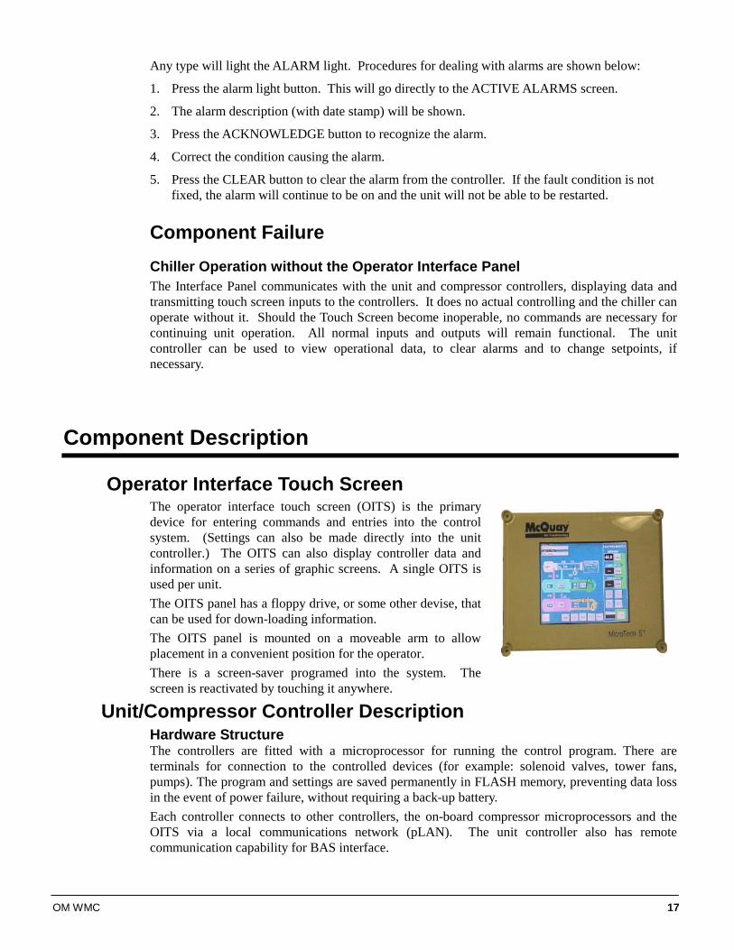
Operator Interface Touch Screen The operator interface touch screen (OITS) is the primary device for entering commands and entries into the control system. (Settings can also be made directly into the unit controller.) The OITS can also display controller data and information on a series of graphic screens. A single OITS is used per unit. The OITS panel has a floppy drive, or some other devise, that can be used for down-loading information. The OITS panel is mounted on a moveable arm to allow placement in a convenient position for the operator. There is a screen-saver programed into the system. The screen is reactivated by touching it anywhere.
Unit/Compressor Controller Description Hardware Structure The controllers are fitted with a microprocessor for running the control program. There are terminals for connection to the controlled devices (for example: solenoid valves, tower fans, pumps). The program and settings are saved permanently in FLASH memory, preventing data loss in the event of power failure, without requiring a back-up battery. Each controller connects to other controllers, the on-board compressor microprocessors and the OITS via a local communications network (pLAN). The unit controller also has remote communication capability for BAS interface.
18 OM WMC
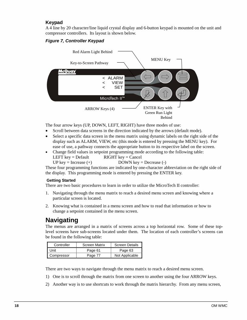
Keypad A 4 line by 20 character/line liquid crystal display and 6-button keypad is mounted on the unit and compressor controllers. Its layout is shown below.
Figure 7, Controller Keypad
Air Condit ioning
ALARMVIEW
SET
<<<
The four arrow keys (UP, DOWN, LEFT, RIGHT) have three modes of use: • Scroll between data screens in the direction indicated by the arrows (default mode). • Select a specific data screen in the menu matrix using dynamic labels on the right side of the
display such as ALARM, VIEW, etc (this mode is entered by pressing the MENU key). For ease of use, a pathway connects the appropriate button to its respective label on the screen.
• Change field values in setpoint programming mode according to the following table: LEFT key = Default RIGHT key = Cancel UP key = Increase (+) DOWN key = Decrease (-) These four programming functions are indicated by one-character abbreviation on the right side of the display. This programming mode is entered by pressing the ENTER key.
Getting Started There are two basic procedures to learn in order to utilize the MicroTech II controller:
1. Navigating through the menu matrix to reach a desired menu screen and knowing where a particular screen is located.
2. Knowing what is contained in a menu screen and how to read that information or how to change a setpoint contained in the menu screen.
Navigating The menus are arranged in a matrix of screens across a top horizontal row. Some of these top-level screens have sub-screens located under them. The location of each controller’s screens can be found in the following table:
Controller Screen Matrix Screen Details Unit Page 61 Page 63 Compressor Page 77 Not Applicable
There are two ways to navigate through the menu matrix to reach a desired menu screen.
1) One is to scroll through the matrix from one screen to another using the four ARROW keys.
2) Another way is to use shortcuts to work through the matrix hierarchy. From any menu screen,
ENTER Key with Green Run Light
Behind
MENU Key
ARROW Keys (4)
Key-to-Screen Pathway
Red Alarm Light Behind
OM WMC 19
a) Pressing the MENU key will take you to the top level of the hierarchy. The display will show ALARM, VIEW, and SET as shown in Figure 7. One of these choices can then be selected by pressing the key connected to it via the pathway shown in the figure.
b) Depending on the top-level selected, a second level of screens will appear. For example, selecting ALARM will go the next level of menus under ALARM (ALARM LOG or ACTIVE ALARM). Selecting VIEW will go the next level of menus (VIEW COMPRESSOR STATUS, VIEW UNIT STATUS, VIEW EVAPORATOR, or VIEW CONDENSER). Selecting SET will go to a series of menus for looking at and changing setpoints.
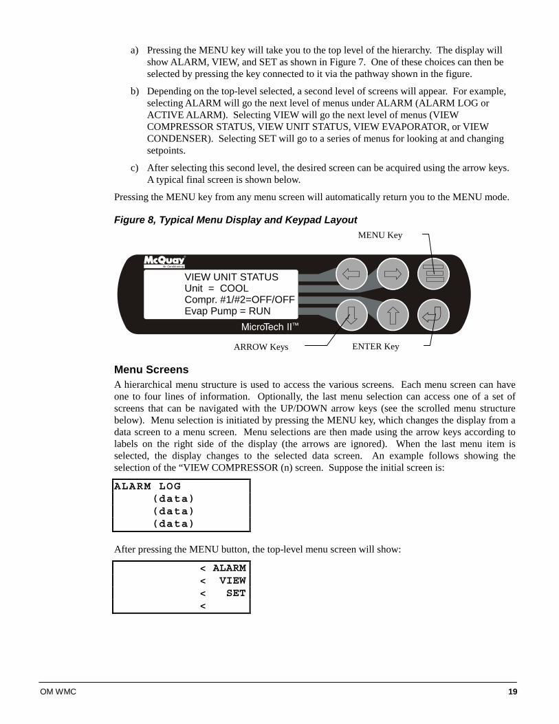
c) After selecting this second level, the desired screen can be acquired using the arrow keys. A typical final screen is shown below.
Pressing the MENU key from any menu screen will automatically return you to the MENU mode.
Figure 8, Typical Menu Display and Keypad Layout
Air Conditioning
VIEW UNIT STATUSUnit = COOLCompr. #1/#2=OFF/OFFEvap Pump = RUN
Menu Screens A hierarchical menu structure is used to access the various screens. Each menu screen can have one to four lines of information. Optionally, the last menu selection can access one of a set of screens that can be navigated with the UP/DOWN arrow keys (see the scrolled menu structure below). Menu selection is initiated by pressing the MENU key, which changes the display from a data screen to a menu screen. Menu selections are then made using the arrow keys according to labels on the right side of the display (the arrows are ignored). When the last menu item is selected, the display changes to the selected data screen. An example follows showing the selection of the “VIEW COMPRESSOR (n) screen. Suppose the initial screen is:
ALARM LOG(data)(data)(data)
After pressing the MENU button, the top-level menu screen will show:
< ALARM< VIEW< SET<
MENU Key
ENTER Key ARROW Keys
20 OM WMC
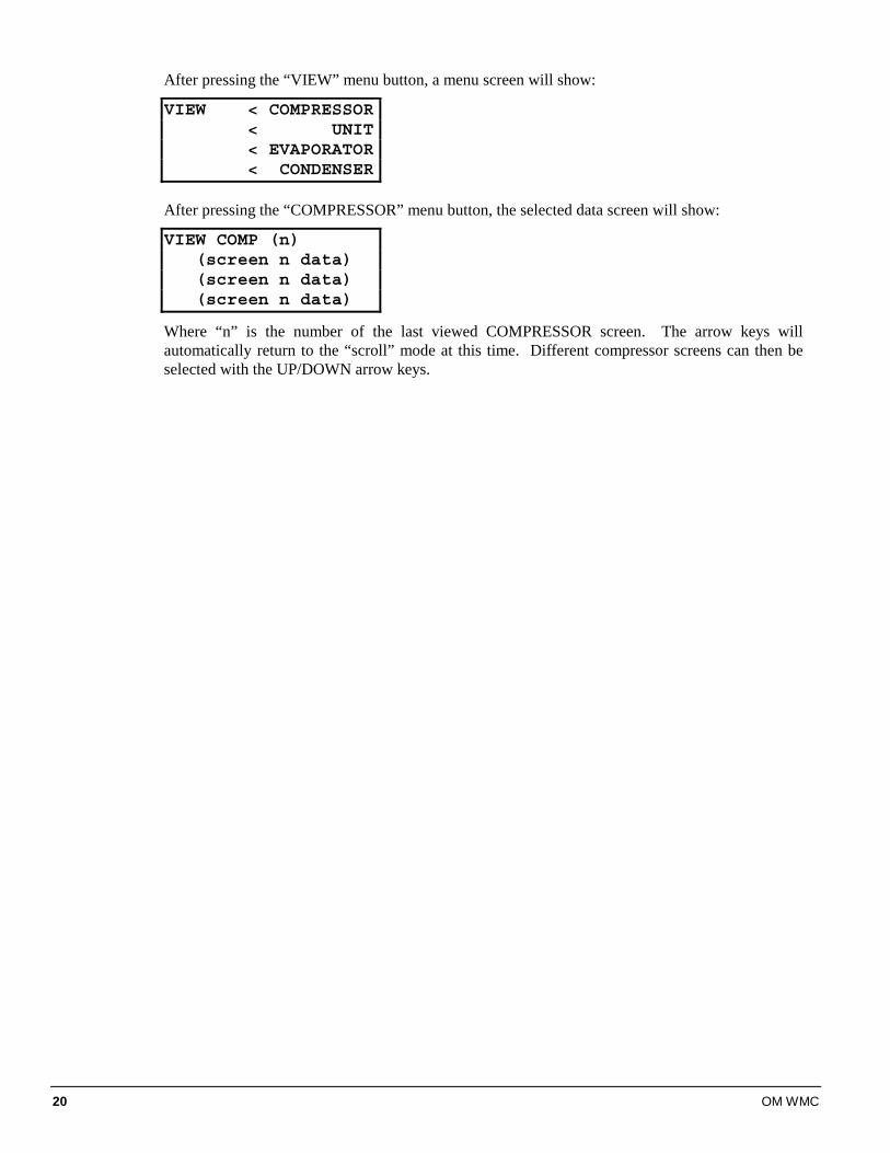
After pressing the “VIEW” menu button, a menu screen will show:
VIEW < COMPRESSOR< UNIT< EVAPORATOR< CONDENSER
After pressing the “COMPRESSOR” menu button, the selected data screen will show:
VIEW COMP (n)(screen n data)(screen n data)(screen n data)
Where “n” is the number of the last viewed COMPRESSOR screen. The arrow keys will automatically return to the “scroll” mode at this time. Different compressor screens can then be selected with the UP/DOWN arrow keys.
OM WMC 21
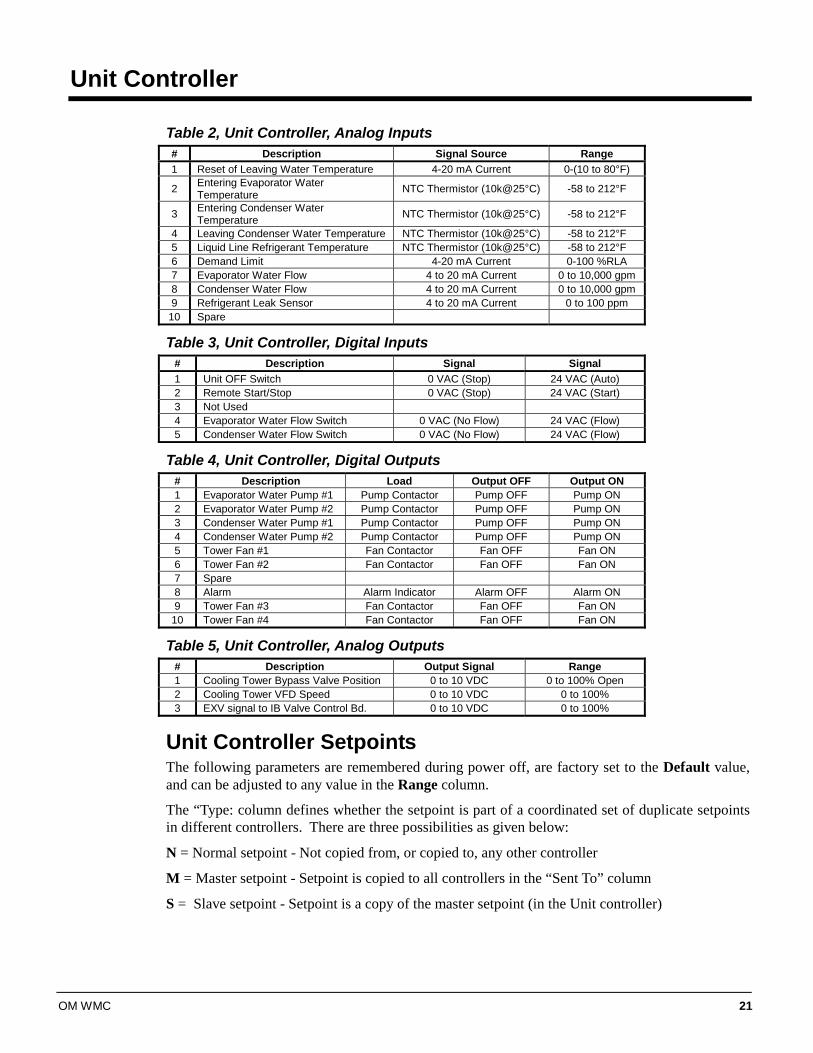
Unit Controller Table 2, Unit Controller, Analog Inputs # Description Signal Source Range 1 Reset of Leaving Water Temperature 4-20 mA Current 0-(10 to 80°F)
2 Entering Evaporator Water Temperature NTC Thermistor (10k@25°C) -58 to 212°F
3 Entering Condenser Water Temperature NTC Thermistor (10k@25°C) -58 to 212°F
4 Leaving Condenser Water Temperature NTC Thermistor (10k@25°C) -58 to 212°F 5 Liquid Line Refrigerant Temperature NTC Thermistor (10k@25°C) -58 to 212°F 6 Demand Limit 4-20 mA Current 0-100 %RLA 7 Evaporator Water Flow 4 to 20 mA Current 0 to 10,000 gpm 8 Condenser Water Flow 4 to 20 mA Current 0 to 10,000 gpm 9 Refrigerant Leak Sensor 4 to 20 mA Current 0 to 100 ppm
10 Spare
Table 3, Unit Controller, Digital Inputs # Description Signal Signal 1 Unit OFF Switch 0 VAC (Stop) 24 VAC (Auto) 2 Remote Start/Stop 0 VAC (Stop) 24 VAC (Start) 3 Not Used 4 Evaporator Water Flow Switch 0 VAC (No Flow) 24 VAC (Flow) 5 Condenser Water Flow Switch 0 VAC (No Flow) 24 VAC (Flow)
Table 4, Unit Controller, Digital Outputs # Description Load Output OFF Output ON 1 Evaporator Water Pump #1 Pump Contactor Pump OFF Pump ON 2 Evaporator Water Pump #2 Pump Contactor Pump OFF Pump ON 3 Condenser Water Pump #1 Pump Contactor Pump OFF Pump ON 4 Condenser Water Pump #2 Pump Contactor Pump OFF Pump ON 5 Tower Fan #1 Fan Contactor Fan OFF Fan ON 6 Tower Fan #2 Fan Contactor Fan OFF Fan ON 7 Spare 8 Alarm Alarm Indicator Alarm OFF Alarm ON 9 Tower Fan #3 Fan Contactor Fan OFF Fan ON
10 Tower Fan #4 Fan Contactor Fan OFF Fan ON
Table 5, Unit Controller, Analog Outputs # Description Output Signal Range 1 Cooling Tower Bypass Valve Position 0 to 10 VDC 0 to 100% Open 2 Cooling Tower VFD Speed 0 to 10 VDC 0 to 100% 3 EXV signal to IB Valve Control Bd. 0 to 10 VDC 0 to 100%
Unit Controller Setpoints The following parameters are remembered during power off, are factory set to the Default value, and can be adjusted to any value in the Range column.
The “Type: column defines whether the setpoint is part of a coordinated set of duplicate setpoints in different controllers. There are three possibilities as given below:
N = Normal setpoint - Not copied from, or copied to, any other controller
M = Master setpoint - Setpoint is copied to all controllers in the “Sent To” column
S = Slave setpoint - Setpoint is a copy of the master setpoint (in the Unit controller)
22 OM WMC
At power-up the slave node checks if the master node is operational and if so, it sets its copy of the setpoint equal to the master’s. Otherwise, the setpoint remains unchanged. During normal operation, any time the master setpoint changes, the slave is updated as well.
The PW (password) column indicates the password that must be active in order to change the setpoint. Codes are as follows:
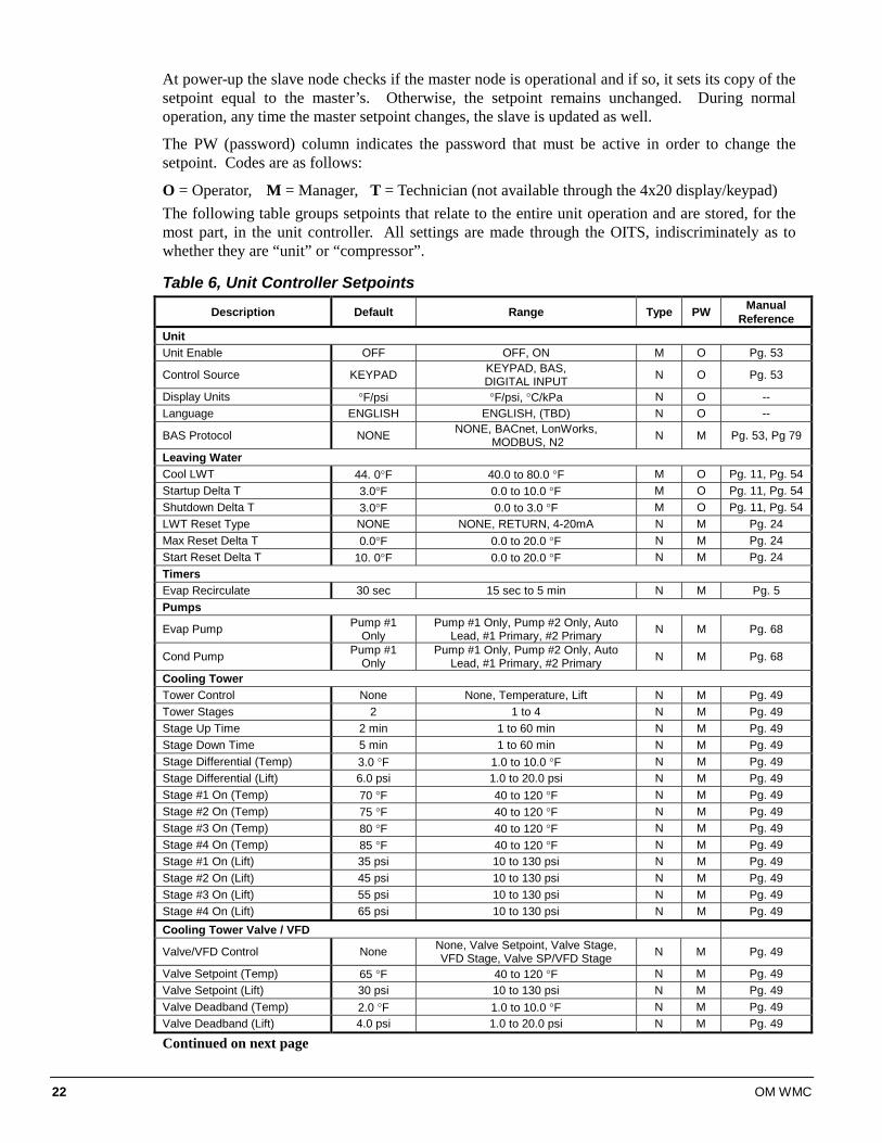
O = Operator, M = Manager, T = Technician (not available through the 4x20 display/keypad) The following table groups setpoints that relate to the entire unit operation and are stored, for the most part, in the unit controller. All settings are made through the OITS, indiscriminately as to whether they are “unit” or “compressor”.
Table 6, Unit Controller Setpoints
Description Default Range Type PW Manual Reference
Unit Unit Enable OFF OFF, ON M O Pg. 53
Control Source KEYPAD KEYPAD, BAS, DIGITAL INPUT N O Pg. 53
Display Units °F/psi °F/psi, °C/kPa N O -- Language ENGLISH ENGLISH, (TBD) N O --
BAS Protocol NONE NONE, BACnet, LonWorks, MODBUS, N2 N M Pg. 53, Pg 79
Leaving Water Cool LWT 44. 0°F 40.0 to 80.0 °F M O Pg. 11, Pg. 54 Startup Delta T 3.0°F 0.0 to 10.0 °F M O Pg. 11, Pg. 54 Shutdown Delta T 3.0°F 0.0 to 3.0 °F M O Pg. 11, Pg. 54 LWT Reset Type NONE NONE, RETURN, 4-20mA N M Pg. 24 Max Reset Delta T 0.0°F 0.0 to 20.0 °F N M Pg. 24 Start Reset Delta T 10. 0°F 0.0 to 20.0 °F N M Pg. 24 Timers Evap Recirculate 30 sec 15 sec to 5 min N M Pg. 5 Pumps
Evap Pump Pump #1 Only
Pump #1 Only, Pump #2 Only, Auto Lead, #1 Primary, #2 Primary N M Pg. 68
Cond Pump Pump #1 Only
Pump #1 Only, Pump #2 Only, Auto Lead, #1 Primary, #2 Primary N M Pg. 68
Cooling Tower Tower Control None None, Temperature, Lift N M Pg. 49 Tower Stages 2 1 to 4 N M Pg. 49 Stage Up Time 2 min 1 to 60 min N M Pg. 49 Stage Down Time 5 min 1 to 60 min N M Pg. 49 Stage Differential (Temp) 3.0 °F 1.0 to 10.0 °F N M Pg. 49 Stage Differential (Lift) 6.0 psi 1.0 to 20.0 psi N M Pg. 49 Stage #1 On (Temp) 70 °F 40 to 120 °F N M Pg. 49 Stage #2 On (Temp) 75 °F 40 to 120 °F N M Pg. 49 Stage #3 On (Temp) 80 °F 40 to 120 °F N M Pg. 49 Stage #4 On (Temp) 85 °F 40 to 120 °F N M Pg. 49 Stage #1 On (Lift) 35 psi 10 to 130 psi N M Pg. 49 Stage #2 On (Lift) 45 psi 10 to 130 psi N M Pg. 49 Stage #3 On (Lift) 55 psi 10 to 130 psi N M Pg. 49 Stage #4 On (Lift) 65 psi 10 to 130 psi N M Pg. 49 Cooling Tower Valve / VFD
Valve/VFD Control None None, Valve Setpoint, Valve Stage, VFD Stage, Valve SP/VFD Stage N M Pg. 49
Valve Setpoint (Temp) 65 °F 40 to 120 °F N M Pg. 49 Valve Setpoint (Lift) 30 psi 10 to 130 psi N M Pg. 49 Valve Deadband (Temp) 2.0 °F 1.0 to 10.0 °F N M Pg. 49 Valve Deadband (Lift) 4.0 psi 1.0 to 20.0 psi N M Pg. 49
Continued on next page
OM WMC 23
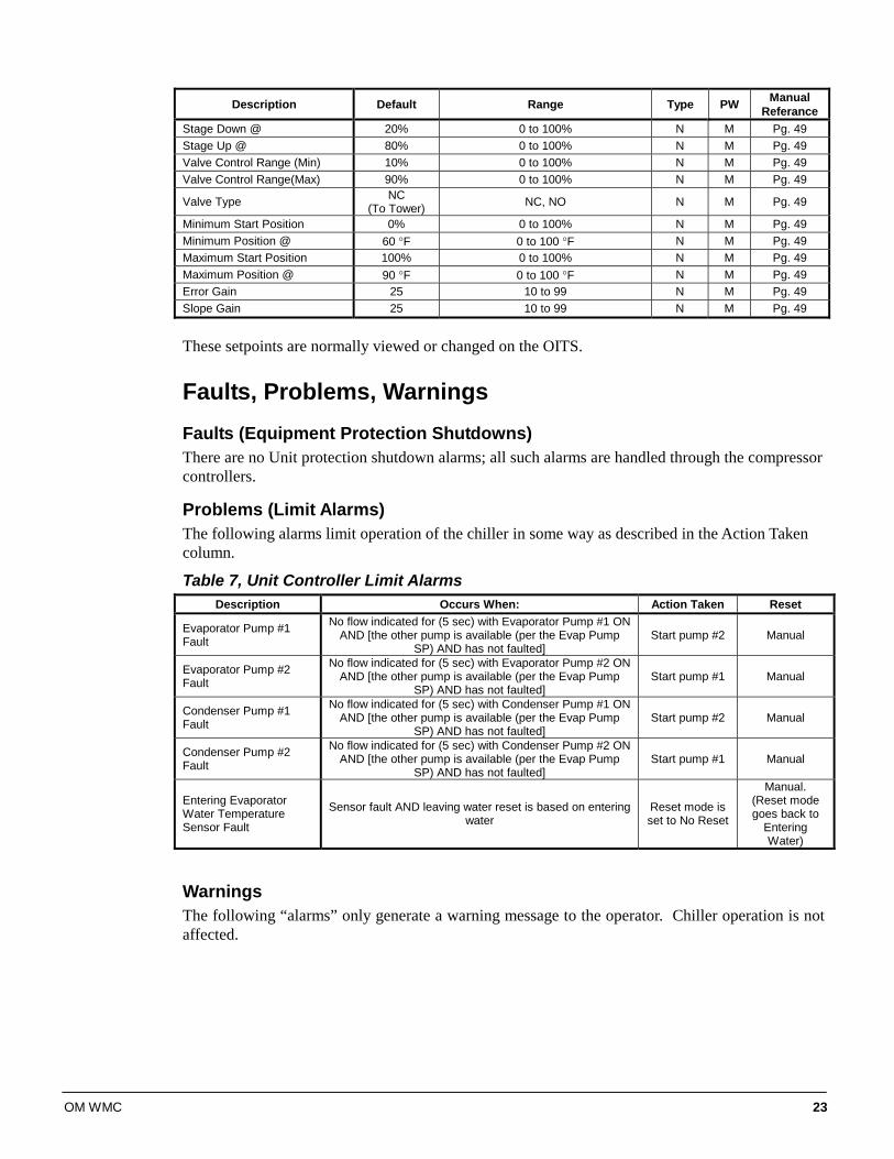
Description Default Range Type PW Manual Referance
Stage Down @ 20% 0 to 100% N M Pg. 49 Stage Up @ 80% 0 to 100% N M Pg. 49 Valve Control Range (Min) 10% 0 to 100% N M Pg. 49 Valve Control Range(Max) 90% 0 to 100% N M Pg. 49
Valve Type NC (To Tower) NC, NO N M Pg. 49
Minimum Start Position 0% 0 to 100% N M Pg. 49 Minimum Position @ 60 °F 0 to 100 °F N M Pg. 49 Maximum Start Position 100% 0 to 100% N M Pg. 49 Maximum Position @ 90 °F 0 to 100 °F N M Pg. 49 Error Gain 25 10 to 99 N M Pg. 49 Slope Gain 25 10 to 99 N M Pg. 49
These setpoints are normally viewed or changed on the OITS.
Faults, Problems, Warnings Faults (Equipment Protection Shutdowns) There are no Unit protection shutdown alarms; all such alarms are handled through the compressor controllers.
Problems (Limit Alarms) The following alarms limit operation of the chiller in some way as described in the Action Taken column.
Table 7, Unit Controller Limit Alarms Description Occurs When: Action Taken Reset
Evaporator Pump #1 Fault
No flow indicated for (5 sec) with Evaporator Pump #1 ON AND [the other pump is available (per the Evap Pump
SP) AND has not faulted] Start pump #2 Manual
Evaporator Pump #2 Fault
No flow indicated for (5 sec) with Evaporator Pump #2 ON AND [the other pump is available (per the Evap Pump
SP) AND has not faulted] Start pump #1 Manual
Condenser Pump #1 Fault
No flow indicated for (5 sec) with Condenser Pump #1 ON AND [the other pump is available (per the Evap Pump
SP) AND has not faulted] Start pump #2 Manual
Condenser Pump #2 Fault
No flow indicated for (5 sec) with Condenser Pump #2 ON AND [the other pump is available (per the Evap Pump
SP) AND has not faulted] Start pump #1 Manual
Entering Evaporator Water Temperature Sensor Fault
Sensor fault AND leaving water reset is based on entering water
Reset mode is set to No Reset
Manual. (Reset mode goes back to
Entering Water)
Warnings The following “alarms” only generate a warning message to the operator. Chiller operation is not affected.
24 OM WMC
Table 8, Unit Controller Warnings Description Occurs When: Action Taken Reset
Entering Evaporator Temperature Sensor Fault Sensor is open or shorted Annunciation Automatic
Entering Condenser Temperature Sensor Fault Sensor is open or shorted Annunciation Automatic
Leaving Condenser Temperature Sensor Fault Sensor is open or shorted Annunciation Automatic
Liquid Line Refrigerant Temperature Sensor Fault Sensor is open or shorted Annunciation Automatic
Unit Controller Functions Leaving Water Temperature (LWT) Reset The Active Leaving Water variable shall be set to the current Leaving Water Temperature (LWT) setpoint unless modified by one of the reset methods below. (The current LWT setpoint is Cool LWT as determined by the chiller mode.) The type of reset in effect is determined by the LWT Reset Type setpoint.
Reset Type – NONE The Active Leaving Water variable is set equal to the current LWT setpoint.
Reset Type – RETURN The Active Leaving Water variable is adjusted by the return water temperature.
When the chiller mode = COOL, the Active Leaving Water variable is reset using the following parameters:
1. Cool LWT setpoint
2. Max Reset Delta T setpoint
3. Start Reset Delta T setpoint
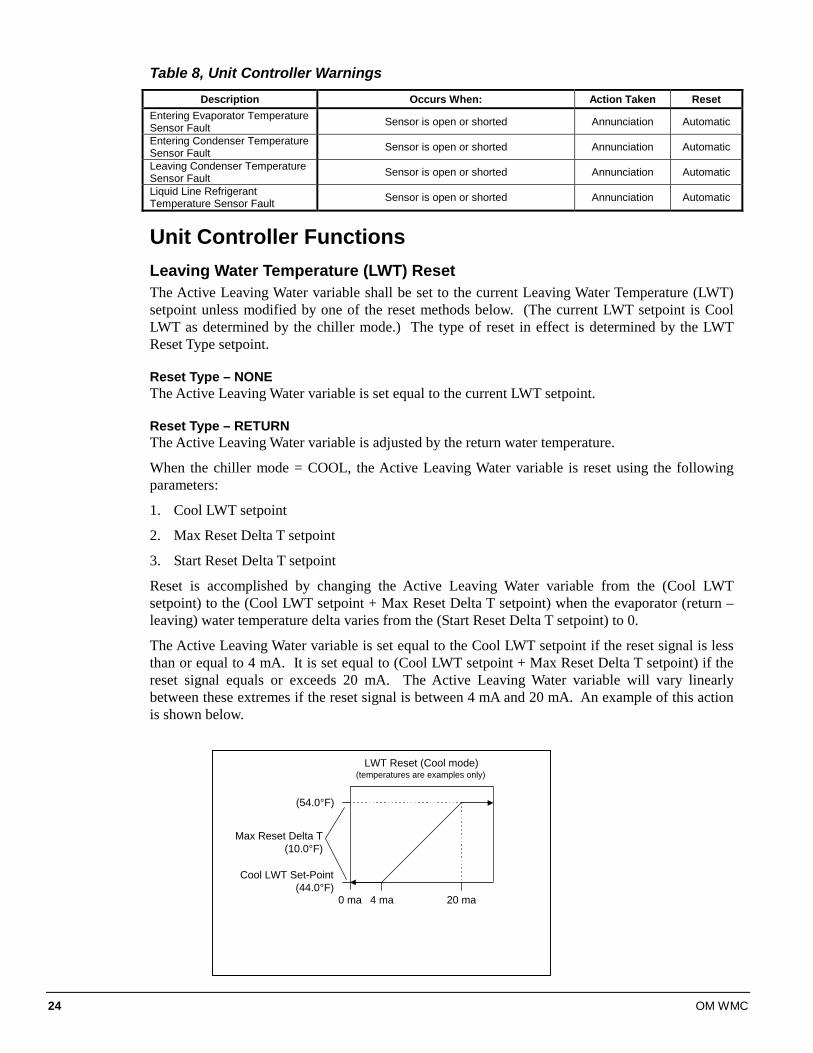
Reset is accomplished by changing the Active Leaving Water variable from the (Cool LWT setpoint) to the (Cool LWT setpoint + Max Reset Delta T setpoint) when the evaporator (return – leaving) water temperature delta varies from the (Start Reset Delta T setpoint) to 0.
The Active Leaving Water variable is set equal to the Cool LWT setpoint if the reset signal is less than or equal to 4 mA. It is set equal to (Cool LWT setpoint + Max Reset Delta T setpoint) if the reset signal equals or exceeds 20 mA. The Active Leaving Water variable will vary linearly between these extremes if the reset signal is between 4 mA and 20 mA. An example of this action is shown below.
20 ma
(54.0°F)
Cool LWT Set-Point(44.0°F)
4 ma
LWT Reset (Cool mode)(temperatures are examples only)
0 ma
Max Reset Delta T(10.0°F)
OM WMC 25
Compressor Controller
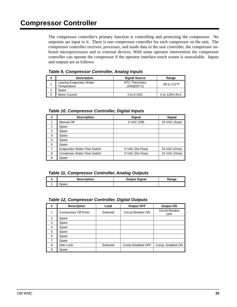
The compressor controller's primary function is controlling and protecting the compressor. No setpoints are input to it. There is one compressor controller for each compressor on the unit. The compressor controller receives, processes, and sends data to the unit controller, the compressor on-board microprocessors and to external devices. With some operator intervention the compressor controller can operate the compressor if the operator interface touch screen is unavailable. Inputs and outputs are as follows:
Table 9, Compressor Controller, Analog Inputs # Description Signal Source Range
1 Leaving Evaporator Water Temperature
NTC Thermistor (10k@25°C) -58 to 212°F
2 Spare 3 Motor Current 0 to 5 VDC 0 to 125% RLA
Table 10, Compressor Controller, Digital Inputs # Description Signal Signal 1 Manual Off 0 VAC (Off) 24 VAC (Auto) 2 Spare 3 Spare 4 Spare 5 Spare 6 Spare 7 Evaporator Water Flow Switch 0 VAC (No Flow) 24 VAC (Flow) 8 Condenser Water Flow Switch 0 VAC (No Flow) 24 VAC (Flow) 9 Spare
Table 11, Compressor Controller, Analog Outputs # Description Output Signal Range 1 Spare
Table 12, Compressor Controller, Digital Outputs # Description Load Output OFF Output ON
1 Compressor Off Emer. Solenoid Circuit Breaker ON Circuit Breaker OFF
2 Spare 3 Spare 4 Spare 5 Spare 6 Spare 7 Spare 8 Inter Lock Solenoid Comp Disabled OFF Comp. Enabled ON 9 Spare
26 OM WMC
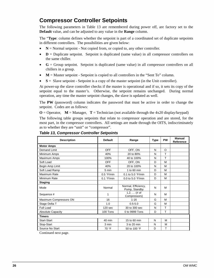
Compressor Controller Setpoints The following parameters in Table 13 are remembered during power off, are factory set to the Default value, and can be adjusted to any value in the Range column.
The “Type: column defines whether the setpoint is part of a coordinated set of duplicate setpoints in different controllers. The possibilities are given below: • N = Normal setpoint - Not copied from, or copied to, any other controller. • D = Duplicate setpoint. Setpoint is duplicated (same value) in all compressor controllers on
the same chiller. • G = Group setpoint. Setpoint is duplicated (same value) in all compressor controllers on all
chillers in a group. • M = Master setpoint - Setpoint is copied to all controllers in the “Sent To” column. • S = Slave setpoint - Setpoint is a copy of the master setpoint (in the Unit controller). At power-up the slave controller checks if the master is operational and if so, it sets its copy of the setpoint equal to the master’s. Otherwise, the setpoint remains unchanged. During normal operation, any time the master setpoint changes, the slave is updated as well.
The PW (password) column indicates the password that must be active in order to change the setpoint. Codes are as follows: O = Operator, M = Manager, T = Technician (not available through the 4x20 display/keypad) The following table groups setpoints that relate to compressor operation and are stored, for the most part, in the compressor controllers. All settings are made through the OITS, indiscriminately as to whether they are “unit” or “compressor”. Table 13, Compressor Controller Setpoints
Description Default Range Type PW Manual Reference
Motor Amps Demand Limit OFF OFF, ON N O Minimum Amps 40% 20 to 80% N T Maximum Amps 100% 40 to 100% N T Soft Load OFF OFF, ON D M Begin Amp Limit 40% 20 to 100% N M Soft Load Ramp 5 min 1 to 60 min D M Maximum Rate 0.5 °F/min 0.1 to 5.0 °F/min D M Minimum Rate 0.1 °F/min 0.0 to 5.0 °F/min D M Staging
Mode Normal Normal, Efficiency, Pump, Standby N M
Sequence # 1 1,2, … (# of Compressors) N M
Maximum Compressors ON 16 1-16 G M Stage Delta T 1.0 0.5-5.0 G M Full Load 120 sec 30 to 300 sec N T Absolute Capacity 100 Tons 0 to 9999 Tons D T Timers Start-Start 40 min 15 to 60 min N M Stop-Start 3 min 3 to 20 min N M Source No Start 70 °F 50 to 100 °F D T Continued next page.
OM WMC 27
Description Default Range Type PW Manual Reference
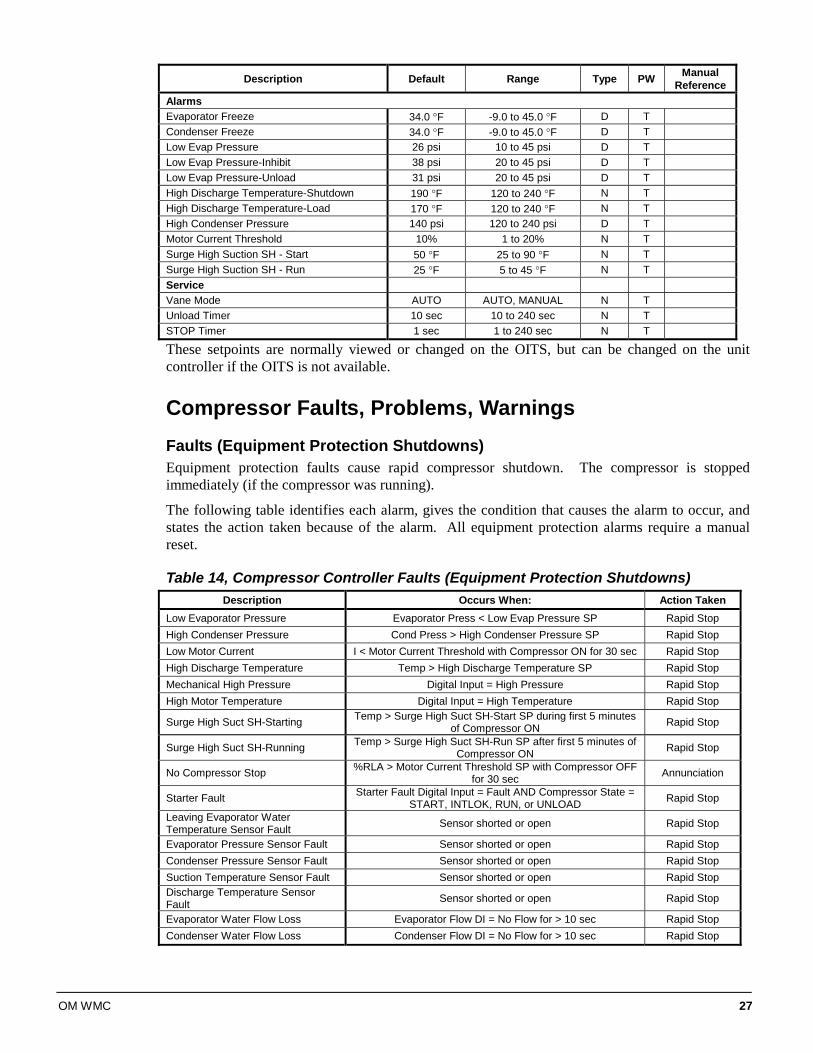
Alarms Evaporator Freeze 34.0 °F -9.0 to 45.0 °F D T Condenser Freeze 34.0 °F -9.0 to 45.0 °F D T Low Evap Pressure 26 psi 10 to 45 psi D T Low Evap Pressure-Inhibit 38 psi 20 to 45 psi D T Low Evap Pressure-Unload 31 psi 20 to 45 psi D T High Discharge Temperature-Shutdown 190 °F 120 to 240 °F N T High Discharge Temperature-Load 170 °F 120 to 240 °F N T High Condenser Pressure 140 psi 120 to 240 psi D T Motor Current Threshold 10% 1 to 20% N T Surge High Suction SH - Start 50 °F 25 to 90 °F N T Surge High Suction SH - Run 25 °F 5 to 45 °F N T Service Vane Mode AUTO AUTO, MANUAL N T Unload Timer 10 sec 10 to 240 sec N T STOP Timer 1 sec 1 to 240 sec N T
These setpoints are normally viewed or changed on the OITS, but can be changed on the unit controller if the OITS is not available.
Compressor Faults, Problems, Warnings Faults (Equipment Protection Shutdowns) Equipment protection faults cause rapid compressor shutdown. The compressor is stopped immediately (if the compressor was running).
The following table identifies each alarm, gives the condition that causes the alarm to occur, and states the action taken because of the alarm. All equipment protection alarms require a manual reset.
Table 14, Compressor Controller Faults (Equipment Protection Shutdowns) Description Occurs When: Action Taken
Low Evaporator Pressure Evaporator Press < Low Evap Pressure SP Rapid Stop High Condenser Pressure Cond Press > High Condenser Pressure SP Rapid Stop Low Motor Current I < Motor Current Threshold with Compressor ON for 30 sec Rapid Stop High Discharge Temperature Temp > High Discharge Temperature SP Rapid Stop Mechanical High Pressure Digital Input = High Pressure Rapid Stop High Motor Temperature Digital Input = High Temperature Rapid Stop
Surge High Suct SH-Starting Temp > Surge High Suct SH-Start SP during first 5 minutes of Compressor ON Rapid Stop
Surge High Suct SH-Running Temp > Surge High Suct SH-Run SP after first 5 minutes of Compressor ON Rapid Stop
No Compressor Stop %RLA > Motor Current Threshold SP with Compressor OFF for 30 sec Annunciation
Starter Fault Starter Fault Digital Input = Fault AND Compressor State = START, INTLOK, RUN, or UNLOAD Rapid Stop
Leaving Evaporator Water Temperature Sensor Fault Sensor shorted or open Rapid Stop
Evaporator Pressure Sensor Fault Sensor shorted or open Rapid Stop Condenser Pressure Sensor Fault Sensor shorted or open Rapid Stop Suction Temperature Sensor Fault Sensor shorted or open Rapid Stop Discharge Temperature Sensor Fault Sensor shorted or open Rapid Stop
Evaporator Water Flow Loss Evaporator Flow DI = No Flow for > 10 sec Rapid Stop Condenser Water Flow Loss Condenser Flow DI = No Flow for > 10 sec Rapid Stop
28 OM WMC
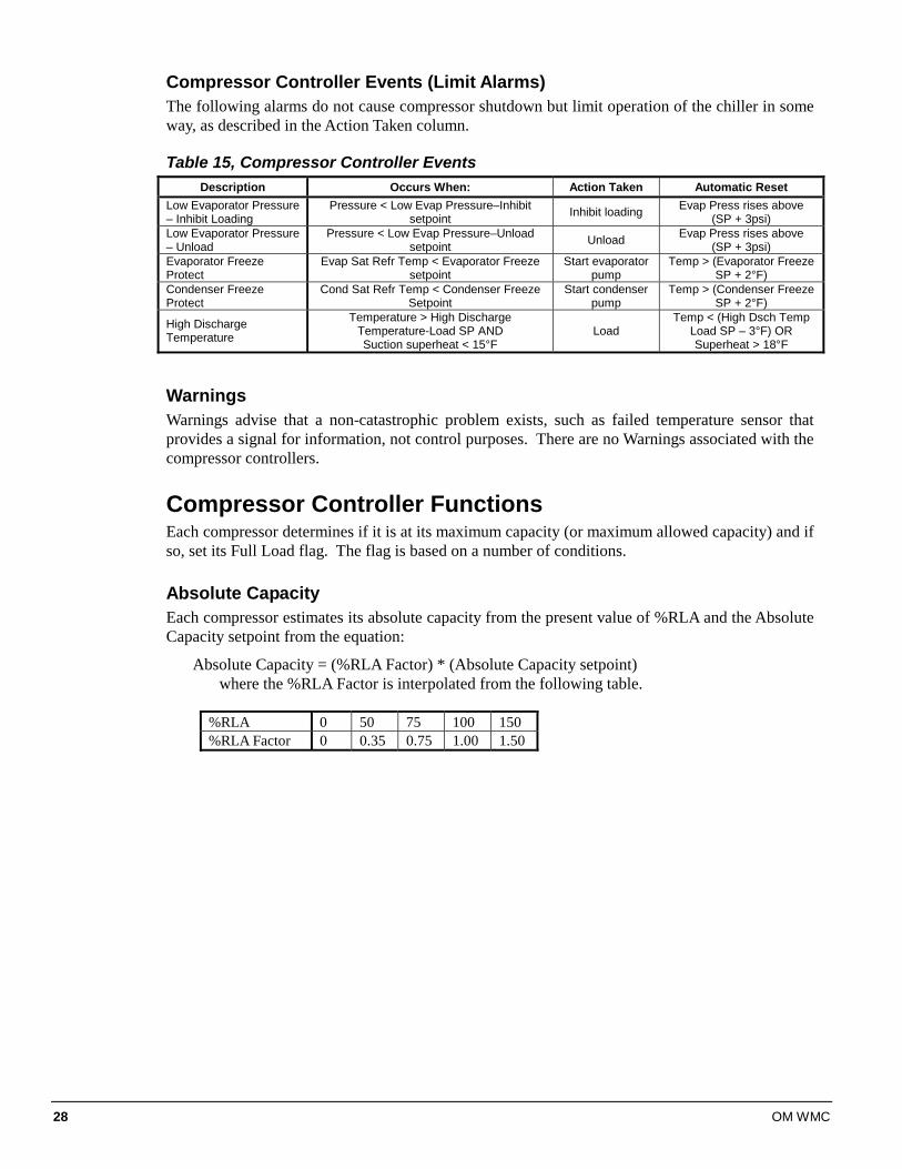
Compressor Controller Events (Limit Alarms) The following alarms do not cause compressor shutdown but limit operation of the chiller in some way, as described in the Action Taken column.
Table 15, Compressor Controller Events Description Occurs When: Action Taken Automatic Reset
Low Evaporator Pressure – Inhibit Loading
Pressure < Low Evap Pressure–Inhibit setpoint Inhibit loading Evap Press rises above
(SP + 3psi) Low Evaporator Pressure – Unload
Pressure < Low Evap Pressure–Unload setpoint Unload Evap Press rises above
(SP + 3psi) Evaporator Freeze Protect
Evap Sat Refr Temp < Evaporator Freeze setpoint
Start evaporator pump
Temp > (Evaporator Freeze SP + 2°F)
Condenser Freeze Protect
Cond Sat Refr Temp < Condenser Freeze Setpoint
Start condenser pump
Temp > (Condenser Freeze SP + 2°F)
High Discharge Temperature
Temperature > High Discharge Temperature-Load SP AND Suction superheat < 15°F
Load Temp < (High Dsch Temp
Load SP – 3°F) OR Superheat > 18°F
Warnings Warnings advise that a non-catastrophic problem exists, such as failed temperature sensor that provides a signal for information, not control purposes. There are no Warnings associated with the compressor controllers.
Compressor Controller Functions Each compressor determines if it is at its maximum capacity (or maximum allowed capacity) and if so, set its Full Load flag. The flag is based on a number of conditions.
Absolute Capacity Each compressor estimates its absolute capacity from the present value of %RLA and the Absolute Capacity setpoint from the equation:
Absolute Capacity = (%RLA Factor) * (Absolute Capacity setpoint) where the %RLA Factor is interpolated from the following table.
%RLA 0 50 75 100 150 %RLA Factor 0 0.35 0.75 1.00 1.50
OM WMC 29
Multiple Compressor Staging This section defines which compressor is the next one to start or stop. The next section defines when the start, or stop, is to occur.
Functions 1. Can start/stop compressors according to an operator defined sequence. 2. Can start compressors based on the number of starts (run hours if starts are equal) and stop on
run hours 3. The above two modes can be combined so that there are two or more groups where all
compressors in the first group are started (based on number of starts/hours) before any in the second group, etc. Conversely, all compressors in a group are stopped (based on run hours) before any in the preceding group, etc.
4. An “efficiency priority” mode can be selected for two or more chillers where one compressor is started on each chiller in the group before a second is started on any of them.
5. A “pump priority” mode can be selected for one or more chillers where all compressors on a given chiller are started before going to the next chiller in the group.
6. One or more compressor can be defined as “standby” where it is never used unless one of the normal compressors is unavailable.
Required Parameters 1. Sequence number setpoint (SQ#_SP) for all compressors. Possible settings = (1-4). 2. Compressor Staging Mode setpoint (CSM_SP) for all compressors. Possible settings are:
NORMAL, EFFICIENCY PRIORITY, PUMP PRIORITY, STANDBY
3. Maximum Number of compressors ON setpoint (MAX_ON_SP). Possible settings = (1-4). This setpoint is the same for all compressors.
4. Number of starts for all compressors. 5. Number of run hours for all compressors. 6. Status of all compressors (On-line, Available/Unavailable, Starting, Running, etc.).
Configuration Rules 1. Each standby compressor must have a sequence number greater than or equal to all non-
standby compressors for which it is in standby. 2. All compressors in an “efficiency priority” or “pump priority” group must be set to the same
sequence number.
30 OM WMC
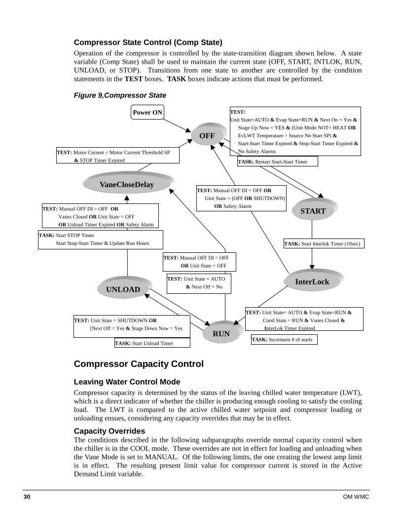
Compressor State Control (Comp State) Operation of the compressor is controlled by the state-transition diagram shown below. A state variable (Comp State) shall be used to maintain the current state (OFF, START, INTLOK, RUN, UNLOAD, or STOP). Transitions from one state to another are controlled by the condition statements in the TEST boxes. TASK boxes indicate actions that must be performed.
Figure 9,Compressor State
Compressor Capacity Control
Leaving Water Control Mode Compressor capacity is determined by the status of the leaving chilled water temperature (LWT), which is a direct indicator of whether the chiller is producing enough cooling to satisfy the cooling load. The LWT is compared to the active chilled water setpoint and compressor loading or unloading ensues, considering any capacity overrides that may be in effect.
Capacity Overrides The conditions described in the following subparagraphs override normal capacity control when the chiller is in the COOL mode. These overrides are not in effect for loading and unloading when the Vane Mode is set to MANUAL. Of the following limits, the one creating the lowest amp limit is in effect. The resulting present limit value for compressor current is stored in the Active Demand Limit variable.
OFF
InterLock
RUN
UNLOAD
VaneCloseDelay
TEST: Unit State=AUTO & Evap State=RUN & Next On = Yes & Stage Up Now = YES & (Unit Mode NOT= HEAT OR EvLWT Temperature > Source No Start SP) & Start-Start Timer Expired & Stop-Start Timer Expired & No Safety Alarms
START
TASK: Start Interlok Timer (10sec)
TEST: Unit State= AUTO & Evap State=RUN & Cond State = RUN & Vanes Closed & InterLok Timer Expired
TEST: Unit State = SHUTDOWN OR [Next Off = Yes & Stage Down Now = Yes
TASK: Start Unload Timer
TASK: Start STOP Timer Start Stop-Start Timer & Update Run Hours
TEST: Manual OFF DI = OFF OR Vanes Closed OR Unit State = OFF OR Unload Timer Expired OR Safety Alarm
TEST: Motor Current < Motor Current Threshold SP & STOP Timer Expired
TEST: Manual OFF DI = OFF OR Unit State = OFF
TEST: Manual OFF DI = OFF OR Unit State = (OFF OR SHUTDOWN) OR Safety Alarm
Power ON
TASK: Increment # of starts
TEST: Unit State = AUTO & Next Off = No
TASK: Restart Start-Start Timer
OM WMC 31
Low Evaporator Pressure If the evaporator pressure drops below the Low Evaporator Pressure – Inhibit setpoint, the unit will inhibit capacity increase. If the evaporator pressure drops below the Low Evaporator Pressure - Unload setpoint, the unit will begin capacity decrease.
High Discharge Temperature - Load If the discharge temperature rises above the High Discharge Temperature - Load setpoint and the motor current is < 50% RLA, the unit will begin capacity increase.
Soft Load
Soft Loading is a configurable function used at compressor startup to limit the maximum current draw on the compressor in a ramp-up type manner. It is only active on the first compressor to start. The setpoints that control this function are:
• Soft Load – (ON/OFF)
• Begin Amp Limit – (%RLA)
• Maximum Amps – (%RLA)
• Soft Load Ramp – (seconds)
The active soft load limit value (in %RLA) increases linearly from the Begin Amp Limit setpoint to the Maximum Amps setpoint over the amount of time specified by the Soft Load Ramp setpoint. If the amp draw rises above the currently active soft load limit value, the unit will inhibit capacity increases. If the amp draw rises to 5% or more above this value, the unit will begin capacity decrease.
Maximum LWT Rate The maximum rate at which the leaving water temperature can drop (chiller mode = COOL) is limited at all times by the Maximum Rate setpoint. If the rate exceeds this setpoint, capacity increases is inhibited.
Demand Limit The maximum amp draw of the compressor can be limited by a 4 to 20 mA signal on the Demand Limit analog input. This function is only enabled if the Demand Limit setpoint is set to ON. The amp limit decreases linearly from the Maximum Amp Limit setpoint (at 4 mA) to the Minimum Amp Limit setpoint (at 20mA). If the amp draw rises above the limit value, the unit will inhibit capacity increases. If the amp draw rises to 5% or more above this value, the unit will begin capacity decrease.
Network Limit The maximum amp draw of the compressor can be limited by a value sent through a BAS network connection and stored in the Network Limit variable. If the amp draw rises above the limit value, the unit will inhibit capacity increases. If the amp draw rises to 5% or more above this value, the unit will begin capacity decrease.
Minimum Amp Limit The minimum amp draw of the compressor can be limited by the Minimum Amps setpoint. If the amp draw drops below the limit value, the unit will inhibit capacity decrease.
Maximum Amp Limit The maximum amp draw of the compressor is always limited by the Maximum Amps setpoint. This limit has priority over all other functions including manual capacity control. If the amp draw rises above the limit value, the unit will inhibit capacity increases. If the amp draw rises to 5% or more above this value, the unit will begin capacity decrease.
32 OM WMC
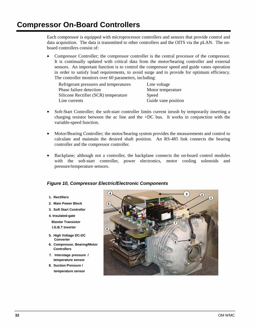
Compressor On-Board Controllers Each compressor is equipped with microprocessor controllers and sensors that provide control and data acquisition. The data is transmitted to other controllers and the OITS via the pLAN. The on-board controllers consist of:
• Compressor Controller; the compressor controller is the central processor of the compressor. It is continually updated with critical data from the motor/bearing controller and external sensors. An important function is to control the compressor speed and guide vanes operation in order to satisfy load requirements, to avoid surge and to provide for optimum efficiency. The controller monitors over 60 parameters, including:
Refrigerant pressures and temperatures Line voltage Phase failure detection Motor temperature Silicone Rectifier (SCR) temperature Speed Line currents Guide vane position
• Soft-Start Controller; the soft-start controller limits current inrush by temporarily inserting a
charging resistor between the ac line and the +DC bus. It works in conjunction with the variable-speed function.
• Motor/Bearing Controller; the motor/bearing system provides the measurements and control to
calculate and maintain the desired shaft position. An RS-485 link connects the bearing controller and the compressor controller.
• Backplane; although not a controller, the backplane connects the on-board control modules
with the soft-start controller, power electronics, motor cooling solenoids and pressure/temperature sensors.
Figure 10, Compressor Electric/Electronic Components
1234
5
6
7
8
1. Rectifiers
2. Main Power Block
3. Soft Start Controller
4. Insulated-gate
5. High Voltage DC-DC Converter
6. Compressor, Bearing/Motor Controllers
7. Interstage pressure / temperature sensor8. Suction Pressure / temperature sensor
Bipolar TransistorI.G.B.T Inverter
OM WMC 33
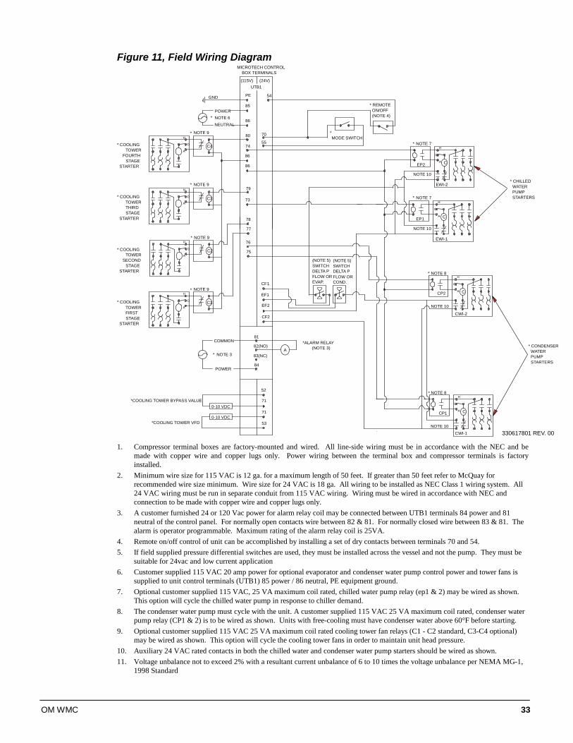
Figure 11, Field Wiring Diagram
80
* CHILLED WATER PUMP STARTERS
EWI-2
CP2
CP1
NOTE 10
NOTE 10
NOTE 10
* NOTE 7
NOTE 7
NOTE 8
H
O
A
C4
* COOLING TOWER FIRST STAGE
STARTER
* COOLING TOWER
SECOND STAGE
STARTER
* COOLING TOWER THIRD STAGE
STARTER
* COOLING TOWER
FOURTH STAGE
STARTER
* NOTE 9H
A
O
C3
* NOTE 9H
A
O
NOTE 9
NOTE 9
79
78
77
74
73
* REMOTE ON/OFF (NOTE 4)
54
86
86
C
CWI-2
CWI-1
(115V) (24V)
MICROTECH CONTROLBOX TERMINALS
55
70
H
A
O
H
A
O
H
O
A C
H
O
A C
H
O
A C
NOTE 10
NOTE 8
EWI-1
C2
C1
*
*
*
*
*
*
UTB1
MODE SWITCH
EF1
76
75
PE
85
86
POWER
NEUTRALNOTE 6*
* CONDENSER WATER PUMP STARTERS
EP2
EP1
GND
330617801 REV. 00
EVAP.FLOW ORDELTA PSWITCH(NOTE 5)
COND.FLOW ORDELTA PSWITCH(NOTE 5)
71
71
53
52
81
84
COMMON
POWER
A82(NO)
83(NC)NOTE 3*
0-10 VDC
0-10 VDC*COOLING TOWER VFD
*ALARM RELAY(NOTE 3)
*COOLING TOWER BYPASS VALUE
CF1
EF2
CF2
1. Compressor terminal boxes are factory-mounted and wired. All line-side wiring must be in accordance with the NEC and be
made with copper wire and copper lugs only. Power wiring between the terminal box and compressor terminals is factory installed.
2. Minimum wire size for 115 VAC is 12 ga. for a maximum length of 50 feet. If greater than 50 feet refer to McQuay for recommended wire size minimum. Wire size for 24 VAC is 18 ga. All wiring to be installed as NEC Class 1 wiring system. All 24 VAC wiring must be run in separate conduit from 115 VAC wiring. Wiring must be wired in accordance with NEC and connection to be made with copper wire and copper lugs only.
3. A customer furnished 24 or 120 Vac power for alarm relay coil may be connected between UTB1 terminals 84 power and 81 neutral of the control panel. For normally open contacts wire between 82 & 81. For normally closed wire between 83 & 81. The alarm is operator programmable. Maximum rating of the alarm relay coil is 25VA.
4. Remote on/off control of unit can be accomplished by installing a set of dry contacts between terminals 70 and 54. 5. If field supplied pressure differential switches are used, they must be installed across the vessel and not the pump. They must be
suitable for 24vac and low current application 6. Customer supplied 115 VAC 20 amp power for optional evaporator and condenser water pump control power and tower fans is
supplied to unit control terminals (UTB1) 85 power / 86 neutral, PE equipment ground. 7. Optional customer supplied 115 VAC, 25 VA maximum coil rated, chilled water pump relay (ep1 & 2) may be wired as shown.
This option will cycle the chilled water pump in response to chiller demand. 8. The condenser water pump must cycle with the unit. A customer supplied 115 VAC 25 VA maximum coil rated, condenser water
pump relay (CP1 & 2) is to be wired as shown. Units with free-cooling must have condenser water above 60°F before starting. 9. Optional customer supplied 115 VAC 25 VA maximum coil rated cooling tower fan relays (C1 - C2 standard, C3-C4 optional)
may be wired as shown. This option will cycle the cooling tower fans in order to maintain unit head pressure. 10. Auxiliary 24 VAC rated contacts in both the chilled water and condenser water pump starters should be wired as shown. 11. Voltage unbalance not to exceed 2% with a resultant current unbalance of 6 to 10 times the voltage unbalance per NEMA MG-1,
1998 Standard
34 OM WMC
Interface Touch Screen
Navigation The home screen shown in VIEW screen on page 36 is usually left on (there is a screen-saver built in that is reactivated by touching the screen anywhere). This VIEW screen contains the STOP and AUTO buttons used to start and stop the unit when in Local control. Other groups of screens can be accessed from the Home screen by pressing one of three buttons on the bottom of the screen; HISTORY, VIEW, SET.
• HISTORY will go to the last history screens viewed and can toggle between the two history screens.
• Trend History
• Alarm History
• VIEW will go to the home View screen. Pressing again will go to the detail View screen used to look in detail at settings and the operation of the chiller. Pressing VIEW from any other screen will return to the Home screen. A new button called MENU will appear when in the View mode. See page 39 for details.
• SET will go to the last Set screen used.
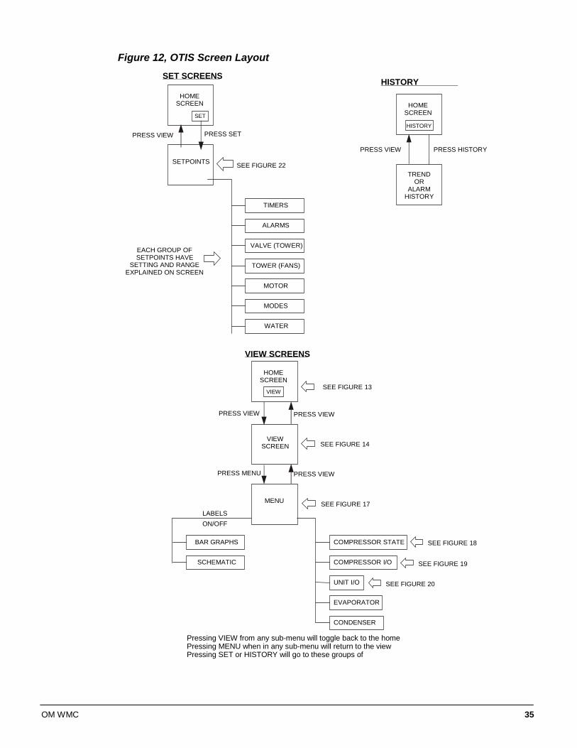
Figure 12on the following page illustrates the arrangement of the various screens available on the OITS. A few minutes practice on an actual OITS should provide an acceptable level of confidence in navigating through the screens.
OM WMC 35
Figure 12, OTIS Screen Layout
HOMESCREEN
SETPOINTS
HOMESCREEN
TRENDOR
ALARMHISTORY
TIMERS
ALARMS
VALVE (TOWER)
TOWER (FANS)
MOTOR
MODES
WATER
SET
PRESS SETPRESS VIEW
SEE FIGURE 22
EACH GROUP OFSETPOINTS HAVE
SETTING AND RANGEEXPLAINED ON SCREEN
HISTORY
PRESS HISTORYPRESS VIEW
SET SCREENS
HOMESCREEN
VIEWSCREEN
COMPRESSOR STATE
COMPRESSOR I/O
UNIT I/O
EVAPORATOR
CONDENSER
VIEW
PRESS VIEWPRESS VIEW
SEE FIGURE 14
BAR GRAPHS
SCHEMATIC
SEE FIGURE 18
SEE FIGURE 19
SEE FIGURE 20
Pressing VIEW from any sub-menu will toggle back to the homePressing MENU when in any sub-menu will return to the viewPressing SET or HISTORY will go to these groups of
VIEW SCREENS
HISTORYSC S
SEE FIGURE 13
PRESS VIEWPRESS MENU
MENU
LABELSON/OFF
SEE FIGURE 17
36 OM WMC
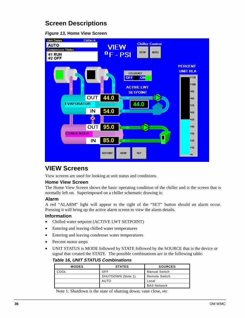
Screen Descriptions Figure 13, Home View Screen
VIEW Screens View screens are used for looking at unit status and conditions. Home View Screen The Home View Screen shows the basic operating condition of the chiller and is the screen that is normally left on. Superimposed on a chiller schematic drawing is: Alarm A red “ALARM” light will appear to the right of the “SET” button should an alarm occur. Pressing it will bring up the active alarm screen to view the alarm details. Information • Chilled water setpoint (ACTIVE LWT SETPOINT) • Entering and leaving chilled water temperatures • Entering and leaving condenser water temperatures • Percent motor amps • UNIT STATUS is MODE followed by STATE followed by the SOURCE that is the device or
signal that created the STATE. The possible combinations are in the following table: Table 16, UNIT STATUS Combinations
MODES STATES SOURCES COOL OFF Manual Switch SHUTDOWN (Note 1) Remote Switch AUTO Local BAS Network
Note 1: Shutdown is the state of shutting down; vane close, etc
OM WMC 37
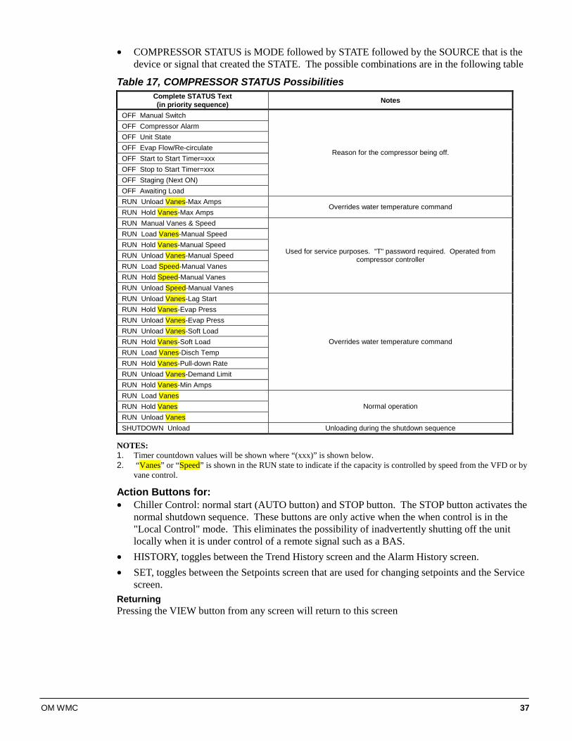
• COMPRESSOR STATUS is MODE followed by STATE followed by the SOURCE that is the device or signal that created the STATE. The possible combinations are in the following table
Table 17, COMPRESSOR STATUS Possibilities Complete STATUS Text (in priority sequence) Notes
OFF Manual Switch OFF Compressor Alarm OFF Unit State OFF Evap Flow/Re-circulate OFF Start to Start Timer=xxx OFF Stop to Start Timer=xxx OFF Staging (Next ON) OFF Awaiting Load
Reason for the compressor being off.
RUN Unload Vanes-Max Amps RUN Hold Vanes-Max Amps
Overrides water temperature command
RUN Manual Vanes & Speed RUN Load Vanes-Manual Speed RUN Hold Vanes-Manual Speed RUN Unload Vanes-Manual Speed RUN Load Speed-Manual Vanes RUN Hold Speed-Manual Vanes RUN Unload Speed-Manual Vanes
Used for service purposes. "T" password required. Operated from compressor controller
RUN Unload Vanes-Lag Start RUN Hold Vanes-Evap Press RUN Unload Vanes-Evap Press RUN Unload Vanes-Soft Load RUN Hold Vanes-Soft Load RUN Load Vanes-Disch Temp RUN Hold Vanes-Pull-down Rate RUN Unload Vanes-Demand Limit RUN Hold Vanes-Min Amps
Overrides water temperature command
RUN Load Vanes RUN Hold Vanes RUN Unload Vanes
Normal operation
SHUTDOWN Unload Unloading during the shutdown sequence
NOTES: 1. Timer countdown values will be shown where “(xxx)” is shown below. 2. “Vanes” or “Speed” is shown in the RUN state to indicate if the capacity is controlled by speed from the VFD or by
vane control.
Action Buttons for: • Chiller Control: normal start (AUTO button) and STOP button. The STOP button activates the
normal shutdown sequence. These buttons are only active when the when control is in the "Local Control" mode. This eliminates the possibility of inadvertently shutting off the unit locally when it is under control of a remote signal such as a BAS.
• HISTORY, toggles between the Trend History screen and the Alarm History screen. • SET, toggles between the Setpoints screen that are used for changing setpoints and the Service
screen. Returning Pressing the VIEW button from any screen will return to this screen
38 OM WMC
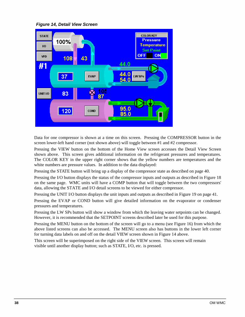
Figure 14, Detail View Screen
Data for one compressor is shown at a time on this screen. Pressing the COMPRESSOR button in the screen lower-left hand corner (not shown above) will toggle between #1 and #2 compressor. Pressing the VIEW button on the bottom of the Home View screen accesses the Detail View Screen shown above. This screen gives additional information on the refrigerant pressures and temperatures. The COLOR KEY in the upper right corner shows that the yellow numbers are temperatures and the white numbers are pressure values. In addition to the data displayed: Pressing the STATE button will bring up a display of the compressor state as described on page 40. Pressing the I/O button displays the status of the compressor inputs and outputs as described in Figure 18 on the same page. WMC units will have a COMP button that will toggle between the two compressors' data, allowing the STATE and I/O detail screens to be viewed for either compressor. Pressing the UNIT I/O button displays the unit inputs and outputs as described in Figure 19 on page 41. Pressing the EVAP or COND button will give detailed information on the evaporator or condenser pressures and temperatures. Pressing the LW SPs button will show a window from which the leaving water setpoints can be changed. However, it is recommended that the SETPOINT screens described later be used for this purpose. Pressing the MENU button on the bottom of the screen will go to a menu (see Figure 16) from which the above listed screens can also be accessed. The MENU screen also has buttons in the lower left corner for turning data labels on and off on the detail VIEW screen shown in Figure 14 above. This screen will be superimposed on the right side of the VIEW screen. This screen will remain visible until another display button; such as STATE, I/O, etc. is pressed.
OM WMC 39
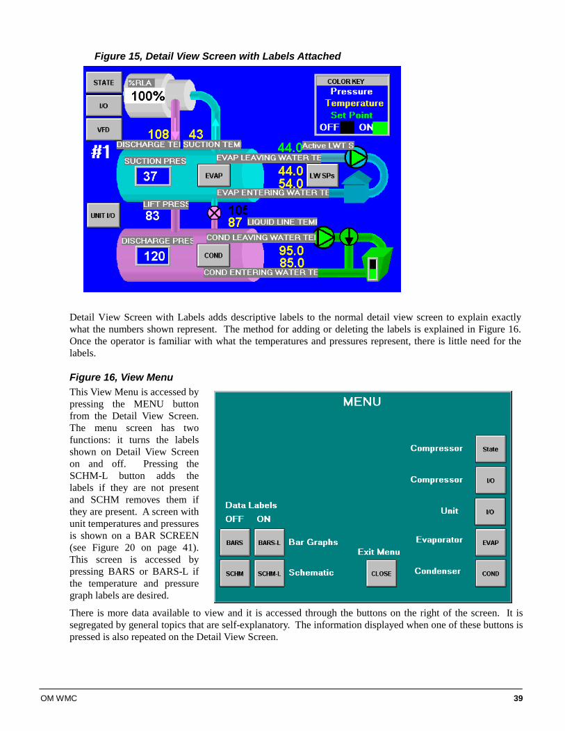
Figure 15, Detail View Screen with Labels Attached
Detail View Screen with Labels adds descriptive labels to the normal detail view screen to explain exactly what the numbers shown represent. The method for adding or deleting the labels is explained in Figure 16. Once the operator is familiar with what the temperatures and pressures represent, there is little need for the labels.
Figure 16, View Menu This View Menu is accessed by pressing the MENU button from the Detail View Screen. The menu screen has two functions: it turns the labels shown on Detail View Screen on and off. Pressing the SCHM-L button adds the labels if they are not present and SCHM removes them if they are present. A screen with unit temperatures and pressures is shown on a BAR SCREEN (see Figure 20 on page 41). This screen is accessed by pressing BARS or BARS-L if the temperature and pressure graph labels are desired.
There is more data available to view and it is accessed through the buttons on the right of the screen. It is segregated by general topics that are self-explanatory. The information displayed when one of these buttons is pressed is also repeated on the Detail View Screen.
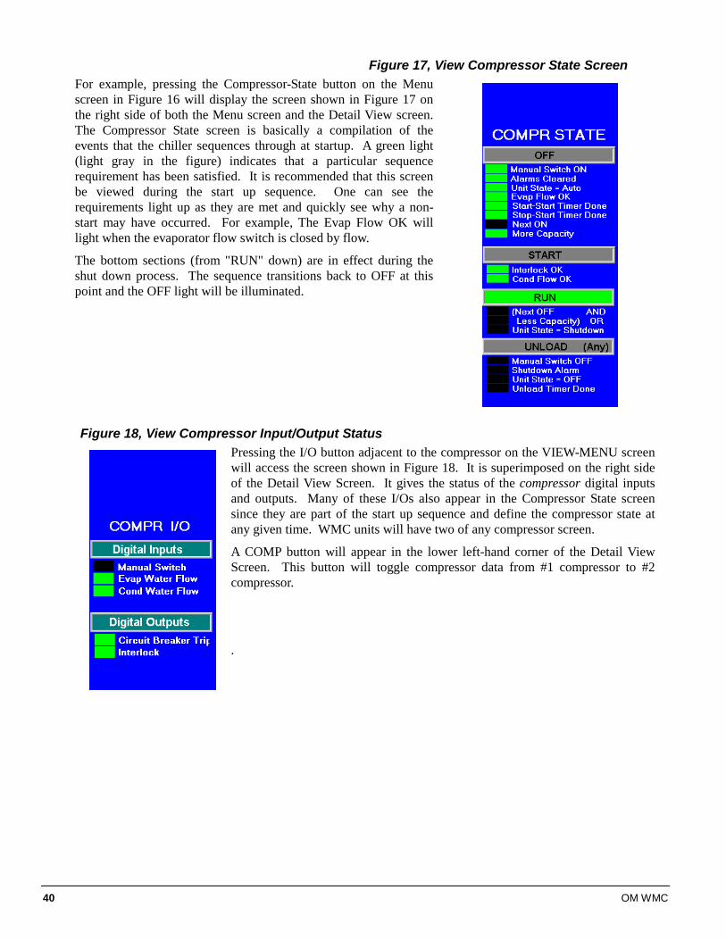
40 OM WMC
Figure 17, View Compressor State Screen For example, pressing the Compressor-State button on the Menu screen in Figure 16 will display the screen shown in Figure 17 on the right side of both the Menu screen and the Detail View screen. The Compressor State screen is basically a compilation of the events that the chiller sequences through at startup. A green light (light gray in the figure) indicates that a particular sequence requirement has been satisfied. It is recommended that this screen be viewed during the start up sequence. One can see the requirements light up as they are met and quickly see why a non-start may have occurred. For example, The Evap Flow OK will light when the evaporator flow switch is closed by flow.
The bottom sections (from "RUN" down) are in effect during the shut down process. The sequence transitions back to OFF at this point and the OFF light will be illuminated.
Figure 18, View Compressor Input/Output Status Pressing the I/O button adjacent to the compressor on the VIEW-MENU screen will access the screen shown in Figure 18. It is superimposed on the right side of the Detail View Screen. It gives the status of the compressor digital inputs and outputs. Many of these I/Os also appear in the Compressor State screen since they are part of the start up sequence and define the compressor state at any given time. WMC units will have two of any compressor screen.
A COMP button will appear in the lower left-hand corner of the Detail View Screen. This button will toggle compressor data from #1 compressor to #2 compressor.
.
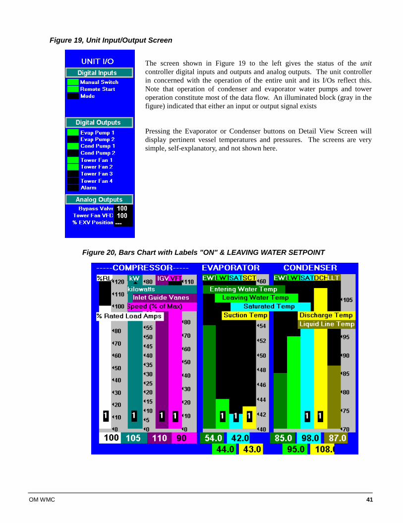
OM WMC 41
Figure 19, Unit Input/Output Screen
The screen shown in Figure 19 to the left gives the status of the unit controller digital inputs and outputs and analog outputs. The unit controller in concerned with the operation of the entire unit and its I/Os reflect this. Note that operation of condenser and evaporator water pumps and tower operation constitute most of the data flow. An illuminated block (gray in the figure) indicated that either an input or output signal exists
Pressing the Evaporator or Condenser buttons on Detail View Screen will display pertinent vessel temperatures and pressures. The screens are very simple, self-explanatory, and not shown here.
Figure 20, Bars Chart with Labels "ON" & LEAVING WATER SETPOINT
42 OM WMC
The bar chart screen is accessed from the MENU screen (Figure 16) by selecting Bar Graphs\BARS-L for the charts with labels attached as shown above or Bar Graphs\BARS for charts without labels.
Pressing “COMP” on the lower left corner of the screen (not shown) will toggle between the unit’s two compressors. Pressing “MENU”, HISTORY”, “VIEW”, or “SET”buttons (not shown) will forward to those respective screens.
SET Screens The set screens on the Interface Panel are used to input the many setpoints associated with equipment of this type. MicroTech II provides an extremely simple method for accomplishing this. (NOTE: If the Interface Panel is unavailable, the unit controller can be used to change setpoints.) Appropriate setpoints are factory set and checked by McQuayService or Factory Authorized Service Company during commissioning. However, adjustments and changes are often required to meet job conditions. Certain settings involving pumps and tower operation are field set. Pressing the SET button found on almost every screen accesses the last SET screen used or the SERVICE screen, whichever of the two was used last. When in any SET screen, pressing the SET button again will toggle to the SERVICE screen shown on page 55.
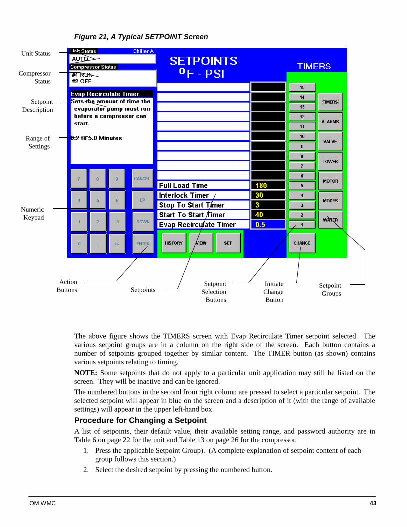
OM WMC 43
Figure 21, A Typical SETPOINT Screen
The above figure shows the TIMERS screen with Evap Recirculate Timer setpoint selected. The various setpoint groups are in a column on the right side of the screen. Each button contains a number of setpoints grouped together by similar content. The TIMER button (as shown) contains various setpoints relating to timing. NOTE: Some setpoints that do not apply to a particular unit application may still be listed on the screen. They will be inactive and can be ignored. The numbered buttons in the second from right column are pressed to select a particular setpoint. The selected setpoint will appear in blue on the screen and a description of it (with the range of available settings) will appear in the upper left-hand box. Procedure for Changing a Setpoint A list of setpoints, their default value, their available setting range, and password authority are in Table 6 on page 22 for the unit and Table 13 on page 26 for the compressor.
1. Press the applicable Setpoint Group). (A complete explanation of setpoint content of each group follows this section.)
2. Select the desired setpoint by pressing the numbered button.
Action Buttons
Setpoint Description
Range of Settings
Numeric Keypad
Initiate Change Button
Setpoint Groups
Compressor Status
Unit Status
SetpointsSetpoint
SelectionButtons
44 OM WMC
3. Press the CHANGE button indicating that you wish to change a setpoint value. The KEYBOARD screen will be turned on automatically to facilitate entering the password. • O = Operator level password is 100 • M = Manager level password is 2001 • T = Technician level password
4. Press the appropriate numbers in the numeric keyboard to enter the password. There is a small delay between pressing the keypad and recording the entry. Be sure that an asterisk appears in the window before pressing the next number. Press ENTER to return to the SETPOINT screen. The password will remain open for 15 minutes after initiation and does not need to be re-entered.
5. Press CHANGE again. The right side of the screen will turn blue (inactive). 6. The numeric keypad and action buttons in the lower left-hand corner of the screen will be
activated (the background will turn green). Setpoints with numeric values can be changed in two ways:
• Select the desired value by pressing the numbered buttons. Press ENTER to enter the value or CANCEL to cancel the transaction.
• Press the UP or DOWN button to increase or decrease the value displayed. Press ENTER to enter the value or CANCEL to cancel the transaction. Some setpoints are text rather than numeric values. For example, LWT Reset Type can be "None" or "4-20 ma". The selection can be made by toggling between choices using the UP or Down button. If dashed lines appear in the setpoint window, it indicates that you have toggled too far and need to reverse direction. Press ENTER to enter the choice or CANCEL to cancel the transaction. Once CHANGE is selected, the CANCEL or ENTER buttons must be pressed before another setpoint can be selected.
7. Additional setpoints can be changed by selecting another setpoint on the screen or by selecting an entirely new group of setpoints.
Explanation of Setpoints Each of the seven setpoint group of screens are detailed in the following section. In many cases the setpoint content is obvious and no explanation is included. 1. TIMERS, for setting timers such as start-to-start, etc. 2. ALARMS, for setting the limit and shutdown alarms. 3. VALVE, sets the parameters for operation of an optional field-installed tower bypass valve. 4. TOWER, selects the method of controlling the cooling tower and sets the parameters for fan
staging/VFD. 5. MOTOR, selects motor related setpoints such as amp limits. Also has maximum and minimum
rate of change of chilled water temperature. 6. MODES, selects various modes of operation such as control source, multiple compressor
staging, pump staging, BAS protocol, etc. 7. WATER, leaving water temperature setpoint, start and stop delta-T, resets, etc.
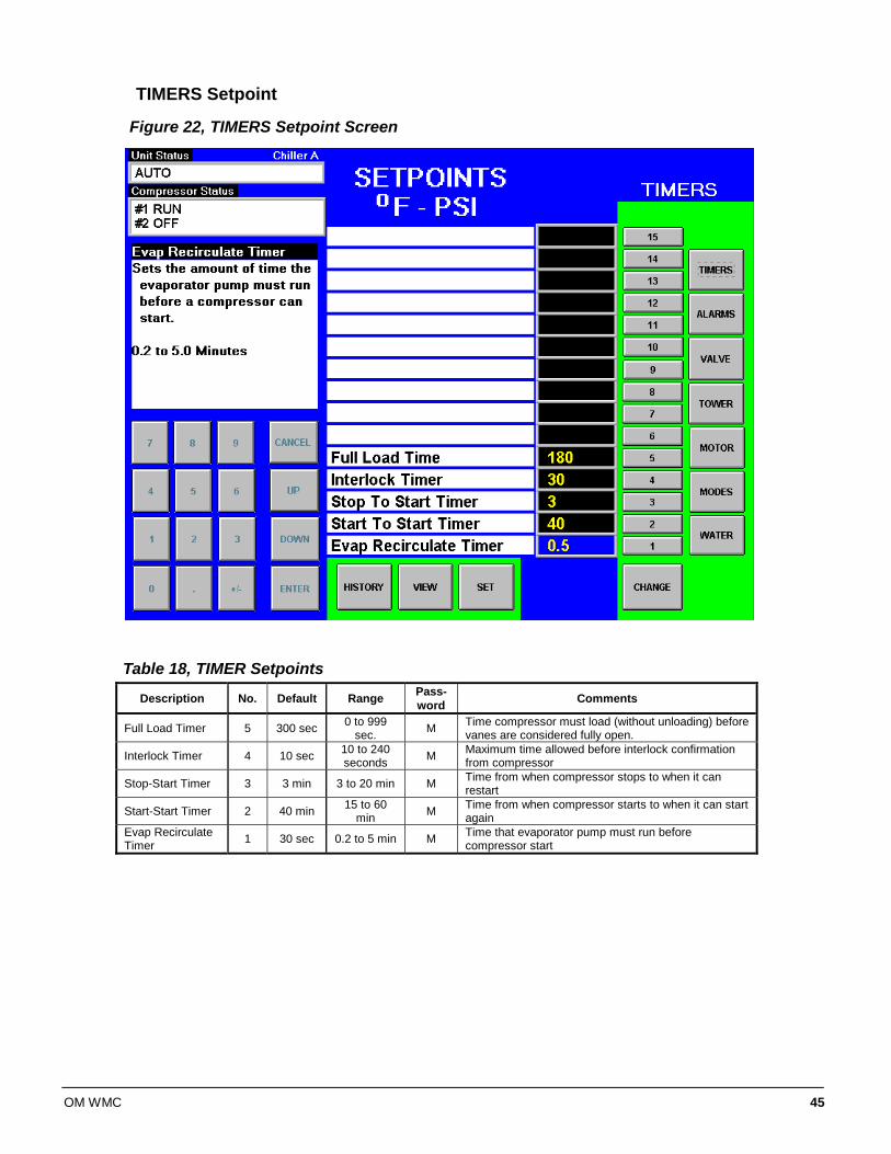
OM WMC 45
TIMERS Setpoint
Figure 22, TIMERS Setpoint Screen
Table 18, TIMER Setpoints
Description No. Default Range Pass-word Comments
Full Load Timer 5 300 sec 0 to 999 sec. M Time compressor must load (without unloading) before
vanes are considered fully open.
Interlock Timer 4 10 sec 10 to 240 seconds M Maximum time allowed before interlock confirmation
from compressor
Stop-Start Timer 3 3 min 3 to 20 min M Time from when compressor stops to when it can restart
Start-Start Timer 2 40 min 15 to 60 min M Time from when compressor starts to when it can start
again Evap Recirculate Timer 1 30 sec 0.2 to 5 min M Time that evaporator pump must run before
compressor start
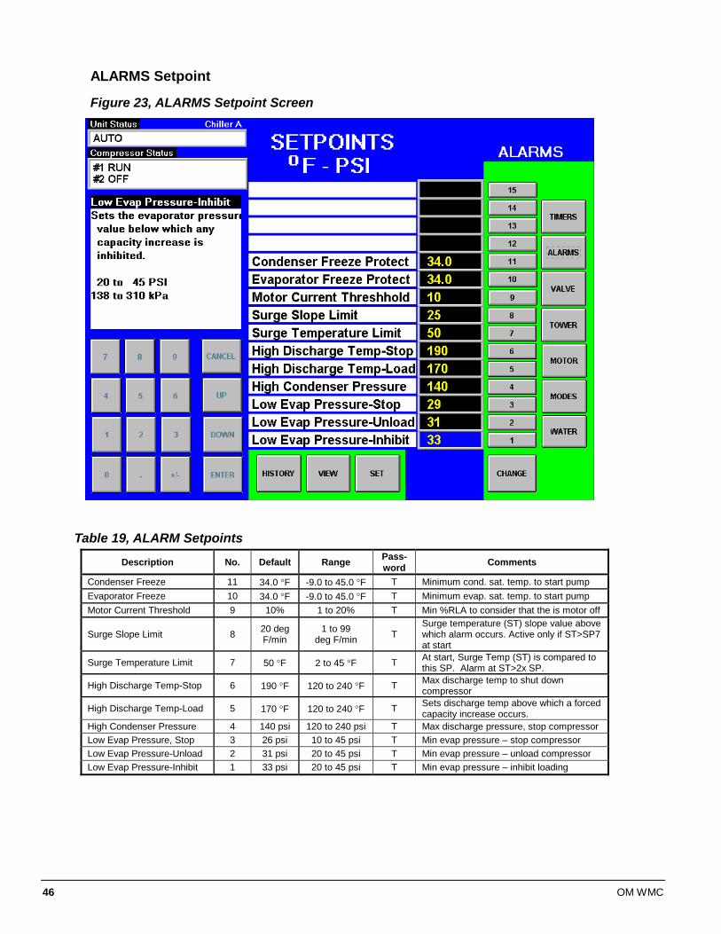
46 OM WMC
ALARMS Setpoint
Figure 23, ALARMS Setpoint Screen
Table 19, ALARM Setpoints
Description No. Default Range Pass-word Comments
Condenser Freeze 11 34.0 °F -9.0 to 45.0 °F T Minimum cond. sat. temp. to start pump Evaporator Freeze 10 34.0 °F -9.0 to 45.0 °F T Minimum evap. sat. temp. to start pump Motor Current Threshold 9 10% 1 to 20% T Min %RLA to consider that the is motor off
Surge Slope Limit 8 20 deg F/min
1 to 99 deg F/min T
Surge temperature (ST) slope value above which alarm occurs. Active only if ST>SP7 at start
Surge Temperature Limit 7 50 °F 2 to 45 °F T At start, Surge Temp (ST) is compared to this SP. Alarm at ST>2x SP.
High Discharge Temp-Stop 6 190 °F 120 to 240 °F T Max discharge temp to shut down compressor
High Discharge Temp-Load 5 170 °F 120 to 240 °F T Sets discharge temp above which a forced capacity increase occurs.
High Condenser Pressure 4 140 psi 120 to 240 psi T Max discharge pressure, stop compressor Low Evap Pressure, Stop 3 26 psi 10 to 45 psi T Min evap pressure – stop compressor Low Evap Pressure-Unload 2 31 psi 20 to 45 psi T Min evap pressure – unload compressor Low Evap Pressure-Inhibit 1 33 psi 20 to 45 psi T Min evap pressure – inhibit loading
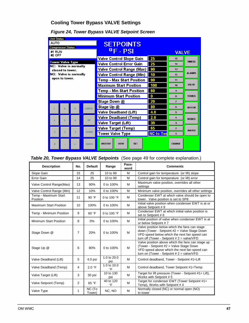
OM WMC 47
Cooling Tower Bypass VALVE Settings
Figure 24, Tower Bypass VALVE Setpoint Screen
Table 20, Tower Bypass VALVE Setpoints (See page 49 for complete explanation.)
Description No. Default Range Pass-word Comments
Slope Gain 15 25 10 to 99 M Control gain for temperature (or lift) slope Error Gain 14 25 10 to 99 M Control gain for temperature (or lift) error
Valve Control Range(Max) 13 90% 0 to 100% M Maximum valve position, overrides all other settings
Valve Control Range (Min) 12 10% 0 to 100% M Minimum valve position, overrides all other settings Temp - Maximum Start Position 11 90 °F 0 to 100 °F M Condenser EWT at which valve should be open to
tower. Valve position is set to SP8
Maximum Start Position 10 100% 0 to 100% M Initial valve position when condenser EWT is at or above Setpoint # 9
Temp - Minimum Position 9 60 °F 0 to 100 °F M Condenser EWT at which initial valve position is set to Setpoint # 6
Minimum Start Position 8 0% 0 to 100% M Initial position of valve when condenser EWT is at or below Setpoint # 7
Stage Down @ 7 20% 0 to 100% M
Valve position below which the fans can stage down (Tower - Setpoint #2 = Valve Stage Down VFD speed below which the next fan speed can turn off (Tower - Setpoint # 2 = valve/VFD
Stage Up @ 6 80% 0 to 100% M
Valve position above which the fans can stage up (Tower - Setpoint #2 = Valve Stage Down VFD speed above which the next fan speed can turn on (Tower - Setpoint # 2 = valve/VFD
Valve Deadband (Lift) 5 4.0 psi 1.0 to 20.0 psi M Control deadband, Tower - Setpoint #1=Lift
Valve Deadband (Temp) 4 2.0 °F 1.0 to 10.0 °F M Control deadband, Tower Setpoint #1=Temp
Valve Target (Lift) 3 30 psi 10 to 130 psi M Target for lift pressure (Tower - Setpoint #1= Lift),
Works with Setpoint # 5
Valve Setpoint (Temp) 2 65 °F 40 to 120 °F M Target for condenser EWT (Tower Setpoint #1=
Temp), Works with Setpoint # 4
Valve Type 1 NC (To Tower) NC, NO M Normally closed (NC) or normal open (NO)
to tower
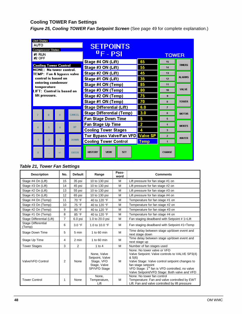
48 OM WMC
Cooling TOWER Fan Settings Figure 25, Cooling TOWER Fan Setpoint Screen (See page 49 for complete explanation.)
Table 21, Tower Fan Settings
Description No. Default Range Pass-word Comments
Stage #4 On (Lift) 15 35 psi 10 to 130 psi M Lift pressure for fan stage #1 on Stage #3 On (Lift) 14 45 psi 10 to 130 psi M Lift pressure for fan stage #2 on Stage #2 On (Lift) 13 55 psi 10 to 130 psi M Lift pressure for fan stage #3 on Stage #1 On (Lift) 12 65 psi 10 to 130 psi M Lift pressure for fan stage #4 on Stage #4 On (Temp) 11 70 °F 40 to 120 °F M Temperature for fan stage #1 on Stage #3 On (Temp) 10 75 °F 40 to 120 °F M Temperature for fan stage #2 on Stage #2 On (Temp) 9 80 °F 40 to 120 °F M Temperature for fan stage #3 on Stage #1 On (Temp) 8 85 °F 40 to 120 °F M Temperature for fan stage #4 on Stage Differential (Lift) 7 6.0 psi 1.0 to 20.0 psi M Fan staging deadband with Setpoint # 1=Lift Stage Differential (Temp) 6 3.0 °F 1.0 to 10.0 °F M Fan staging deadband with Setpoint #1=Temp
Stage Down Time 5 5 min 1 to 60 min M Time delay between stage up/down event and next stage down
Stage Up Time 4 2 min 1 to 60 min M Time delay between stage up/down event and next stage up
Tower Stages 3 2 1 to 4 M Number of fan stages used
Valve/VFD Control 2 None
None, Valve Setpoint, Valve
Stage, VFD Stage, Valve
SP/VFD Stage
M
None: No tower valve or VFD Valve Setpoint: Valve controls to VALVE SP3(4) & 5(6) Valve Stage: Valve control setpoint changes to fan stage setpoint VFD Stage: 1st fan is VFD controlled, no valve Valve Setpoint/VFD Stage: Both valve and VFD
Tower Control 1 None None,
Temperature, Lift
M None: No tower fan control Temperature: Fan and valve controlled by EWT Lift: Fan and valve controlled by lift pressure
OM WMC 49
Explanation of Tower Control Settings The MicroTech II controller can control cooling tower fan stages, a tower bypass valve, and/or a tower fan VFD if the chiller has a dedicated cooling tower. The Tower Bypass Valve position will always control the Tower Fan Staging if Valve Setpoint, Stage Setpoint, or lift is selected. Fan staging is determined by Min & Max Tower Valve Position. There are five possible tower control strategies as noted below and explained in detail later in this section. They are selected from SETPOINT TOWER SP2. 1. NONE, Tower fan staging only, which is not recommended. In this mode the tower fan
staging (up to 4 stages) is controlled by either the condenser Entering Water Temperature (EWT) or LIFT temperature (difference between the condenser and evaporator saturated temperatures). Tower bypass or fan speed are not controlled.
2. VALVE SP, Tower staging with low-limit controlled bypass valve. In this mode the tower fans are controlled as in #1, plus a tower bypass valve is controlled to provide a minimum condenser EWT. There is no interconnection between the fan control and the valve control. 3. VALVE STAGE, Tower staging with stage controlled bypass valve. In this mode the bypass valve controls between fan stages to smooth the control and reduce fan cycling
4. VFD STAGE. In this mode a VFD controls the first fan. Up to 3 more fans are staged on and off and there is no bypass valve.
5. VALVE/VFD, Tower fan control with VFD plus bypass valve control.
1. Tower Fan Staging Only (NONE), This is not a recommended control strategy, The following settings are used for the Tower Fan Staging Only mode, (SP= setpoint) 1) TOWER SETPOINT Screen
a) SP1. Select TEMP if control is based on condenser EWT or LIFT if based on compressor lift expressed in degrees.
b) SP2. Select NONE for no bypass valve or fan VFD control. c) SP3. Select one to four fan outputs depending on the number of fan stages to be used. More
than one fan can be used per stage through the use of relays. d) SP4. Select STAGE UP TIME from 1 to 60 minutes. The default value of 2 minutes is
probably a good starting point. The value may need to be adjusted later depending on actual system operation.
e) SP5. Select STAGE DOWN TIME from 1 to 60 minutes. The default value of 5 minutes is probably a good starting point. The value may need to be adjusted later depending on actual system operation.
f) If TEMP is selected in SP1, use
i) SP6. Select STAGE DIFFERENTIAL in degrees F, start with default of 3 degrees F.
ii) SP8-11. Set the STAGE ON temperatures consistent with the temperature range over which the condenser EWT is desired to operate. The default values of 70°F, 75°F, 80°F and 85°F are a good place to start in climates with moderate wet bulb temperatures. The number of STAGE ON setpoints used must be the same as SP3.
g) If LIFT is selected in SP1, use
i) SP7. Select STAGE DIFFERENTIAL in PSI. Start with default of 6 PSI.
ii) SP12-15. Start with default setpoints. The number of STAGE ON setpoints used must be the same as SP3.
See Figure 11, Field Wiring Diagram on page 33, for fan staging field wiring connection points.
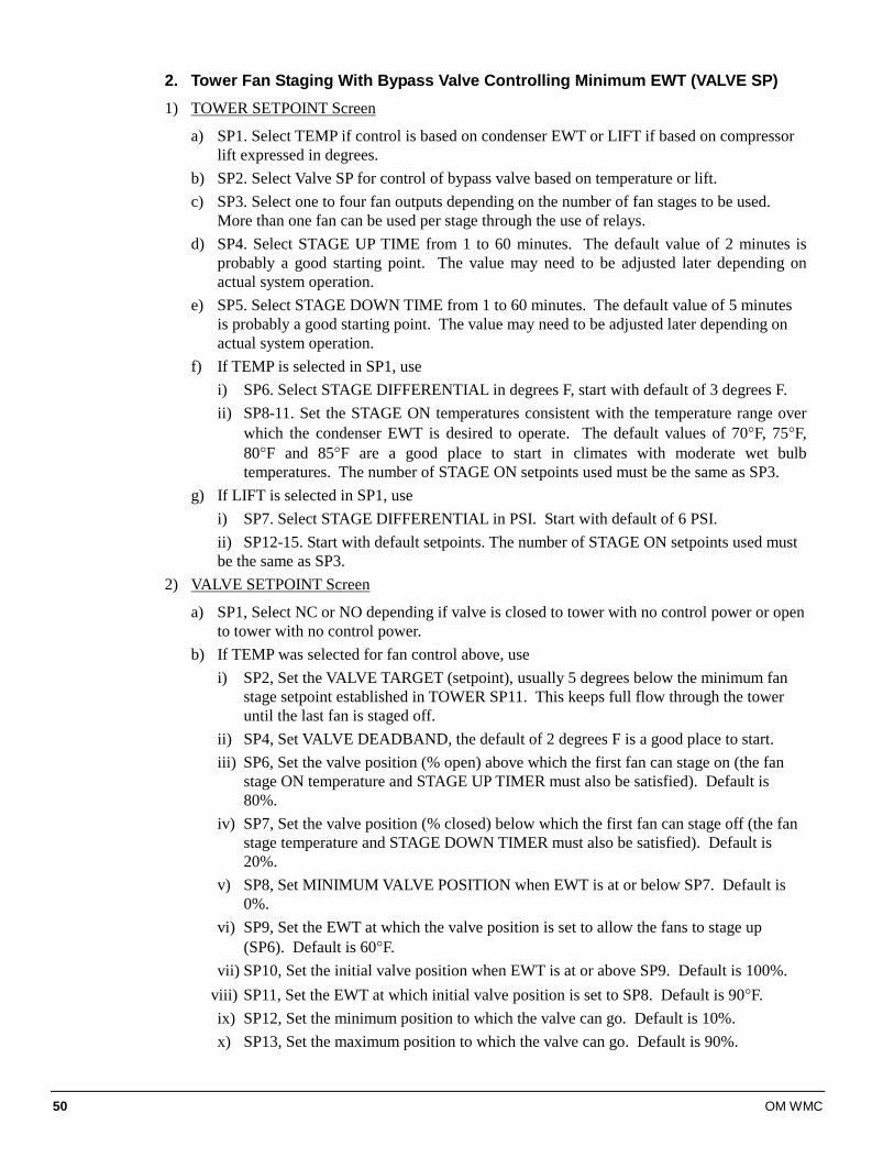
50 OM WMC
2. Tower Fan Staging With Bypass Valve Controlling Minimum EWT (VALVE SP) 1) TOWER SETPOINT Screen
a) SP1. Select TEMP if control is based on condenser EWT or LIFT if based on compressor lift expressed in degrees.
b) SP2. Select Valve SP for control of bypass valve based on temperature or lift. c) SP3. Select one to four fan outputs depending on the number of fan stages to be used.
More than one fan can be used per stage through the use of relays. d) SP4. Select STAGE UP TIME from 1 to 60 minutes. The default value of 2 minutes is
probably a good starting point. The value may need to be adjusted later depending on actual system operation.
e) SP5. Select STAGE DOWN TIME from 1 to 60 minutes. The default value of 5 minutes is probably a good starting point. The value may need to be adjusted later depending on actual system operation.
f) If TEMP is selected in SP1, use i) SP6. Select STAGE DIFFERENTIAL in degrees F, start with default of 3 degrees F. ii) SP8-11. Set the STAGE ON temperatures consistent with the temperature range over
which the condenser EWT is desired to operate. The default values of 70°F, 75°F, 80°F and 85°F are a good place to start in climates with moderate wet bulb temperatures. The number of STAGE ON setpoints used must be the same as SP3.
g) If LIFT is selected in SP1, use i) SP7. Select STAGE DIFFERENTIAL in PSI. Start with default of 6 PSI. ii) SP12-15. Start with default setpoints. The number of STAGE ON setpoints used must be the same as SP3.
2) VALVE SETPOINT Screen
a) SP1, Select NC or NO depending if valve is closed to tower with no control power or open to tower with no control power.
b) If TEMP was selected for fan control above, use i) SP2, Set the VALVE TARGET (setpoint), usually 5 degrees below the minimum fan
stage setpoint established in TOWER SP11. This keeps full flow through the tower until the last fan is staged off.
ii) SP4, Set VALVE DEADBAND, the default of 2 degrees F is a good place to start. iii) SP6, Set the valve position (% open) above which the first fan can stage on (the fan
stage ON temperature and STAGE UP TIMER must also be satisfied). Default is 80%.
iv) SP7, Set the valve position (% closed) below which the first fan can stage off (the fan stage temperature and STAGE DOWN TIMER must also be satisfied). Default is 20%.
v) SP8, Set MINIMUM VALVE POSITION when EWT is at or below SP7. Default is 0%.
vi) SP9, Set the EWT at which the valve position is set to allow the fans to stage up (SP6). Default is 60°F.
vii) SP10, Set the initial valve position when EWT is at or above SP9. Default is 100%. viii) SP11, Set the EWT at which initial valve position is set to SP8. Default is 90°F. ix) SP12, Set the minimum position to which the valve can go. Default is 10%. x) SP13, Set the maximum position to which the valve can go. Default is 90%.
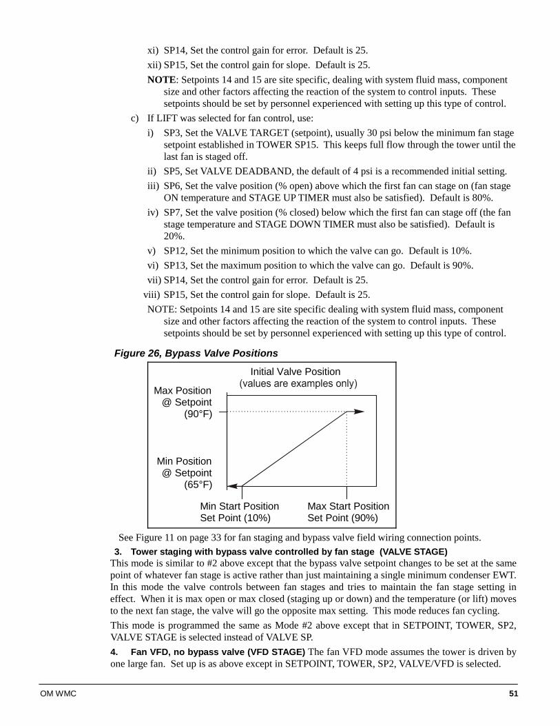
OM WMC 51
xi) SP14, Set the control gain for error. Default is 25. xii) SP15, Set the control gain for slope. Default is 25. NOTE: Setpoints 14 and 15 are site specific, dealing with system fluid mass, component
size and other factors affecting the reaction of the system to control inputs. These setpoints should be set by personnel experienced with setting up this type of control.
c) If LIFT was selected for fan control, use: i) SP3, Set the VALVE TARGET (setpoint), usually 30 psi below the minimum fan stage
setpoint established in TOWER SP15. This keeps full flow through the tower until the last fan is staged off.
ii) SP5, Set VALVE DEADBAND, the default of 4 psi is a recommended initial setting. iii) SP6, Set the valve position (% open) above which the first fan can stage on (fan stage
ON temperature and STAGE UP TIMER must also be satisfied). Default is 80%. iv) SP7, Set the valve position (% closed) below which the first fan can stage off (the fan
stage temperature and STAGE DOWN TIMER must also be satisfied). Default is 20%.
v) SP12, Set the minimum position to which the valve can go. Default is 10%. vi) SP13, Set the maximum position to which the valve can go. Default is 90%. vii) SP14, Set the control gain for error. Default is 25.
viii) SP15, Set the control gain for slope. Default is 25. NOTE: Setpoints 14 and 15 are site specific dealing with system fluid mass, component
size and other factors affecting the reaction of the system to control inputs. These setpoints should be set by personnel experienced with setting up this type of control.
Figure 26, Bypass Valve Positions
Initial Valve Position
Max Start PositionSet Point (90%)
Min Start PositionSet Point (10%)
Max Position@ Setpoint
(90°F)
Min Position@ Setpoint
(65°F)
See Figure 11 on page 33 for fan staging and bypass valve field wiring connection points.
3. Tower staging with bypass valve controlled by fan stage (VALVE STAGE) This mode is similar to #2 above except that the bypass valve setpoint changes to be set at the same point of whatever fan stage is active rather than just maintaining a single minimum condenser EWT. In this mode the valve controls between fan stages and tries to maintain the fan stage setting in effect. When it is max open or max closed (staging up or down) and the temperature (or lift) moves to the next fan stage, the valve will go the opposite max setting. This mode reduces fan cycling. This mode is programmed the same as Mode #2 above except that in SETPOINT, TOWER, SP2, VALVE STAGE is selected instead of VALVE SP. 4. Fan VFD, no bypass valve (VFD STAGE) The fan VFD mode assumes the tower is driven by one large fan. Set up is as above except in SETPOINT, TOWER, SP2, VALVE/VFD is selected.
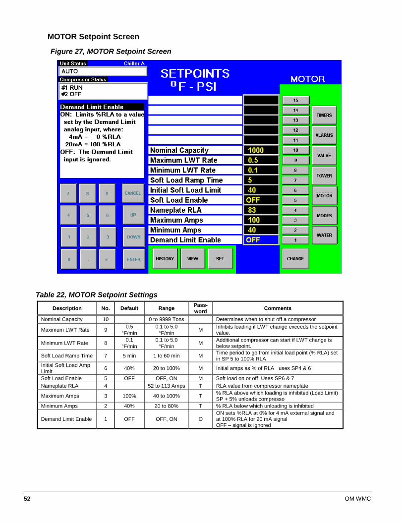
52 OM WMC
MOTOR Setpoint Screen
Figure 27, MOTOR Setpoint Screen
Table 22, MOTOR Setpoint Settings
Description No. Default Range Pass-word Comments
Nominal Capacity 10 0 to 9999 Tons Determines when to shut off a compressor
Maximum LWT Rate 9 0.5 °F/min
0.1 to 5.0 °F/min M Inhibits loading if LWT change exceeds the setpoint
value.
Minimum LWT Rate 8 0.1 °F/min
0.1 to 5.0 °F/min M Additional compressor can start if LWT change is
below setpoint.
Soft Load Ramp Time 7 5 min 1 to 60 min M Time period to go from initial load point (% RLA) set in SP 5 to 100% RLA
Initial Soft Load Amp Limit 6 40% 20 to 100% M Initial amps as % of RLA uses SP4 & 6
Soft Load Enable 5 OFF OFF, ON M Soft load on or off Uses SP6 & 7 Nameplate RLA 4 52 to 113 Amps T RLA value from compressor nameplate
Maximum Amps 3 100% 40 to 100% T % RLA above which loading is inhibited (Load Limit) SP + 5% unloads compresso
Minimum Amps 2 40% 20 to 80% T % RLA below which unloading is inhibited
Demand Limit Enable 1 OFF OFF, ON O ON sets %RLA at 0% for 4 mA external signal and at 100% RLA for 20 mA signal OFF – signal is ignored
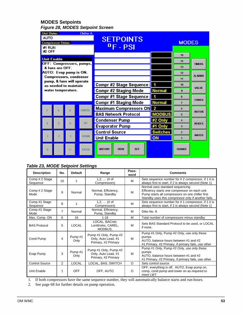
OM WMC 53
MODES Setpoints Figure 28, MODES Setpoint Screen
Table 23, MODE Setpoint Settings
Description No. Default Range Pass-word Comments
Comp # 2 Stage Sequence 10 1 1,2, … (# of
Compressors) M Sets sequence number for # 2 compressor, if 1 it is always first to start, if 2 is always second (Note 1)
Comp # 2 Stage Mode 9 Normal Normal, Efficiency,
Pump, Standby M
Normal uses standard sequencing Efficiency starts one compressor on each unit Pump starts all compressors on one chiller first Standby uses this compressor only if another fails.
Comp #1 Stage Sequence 8 1 1,2, … (# of
Compressors) M Sets sequence number for # 1 compressor, if 1 it is always first to start, if 2 is always second (Note 1)
Comp #1 Stage Mode 7 Normal Normal, Efficiency,
Pump, Standby M Ditto No. 9.
Max. Comp. ON 6 16 1-16 M Total number of compressors minus standby
BAS Protocol 5 LOCAL LOCAL, BACnet,
LonWorks, CAREL, MODBUS,
M Sets BAS Standard Protocol to be used, or LOCAL if none.
Cond Pump 4 Pump #1 Only
Pump #1 Only, Pump #2 Only, Auto Lead, #1 Primary, #2 Primary
M
Pump #1 Only, Pump #2 Only, use only these pumps AUTO, balance hours between #1 and #2 #1 Primary, #2 Primary, if primary fails, use other
Evap Pump 3 Pump #1 Only
Pump #1 Only, Pump #2 Only, Auto Lead, #1 Primary, #2 Primary
M
Pump #1 Only, Pump #2 Only, use only these pumps AUTO, balance hours between #1 and #2 #1 Primary, #2 Primary, if primary fails, use other
Control Source 2 LOCAL LOCAL, BAS, SWITCH O Sets control source
Unit Enable 1 OFF OFF, AUTO O OFF, everything is off. AUTO, Evap pump on, comp, cond pump and tower on as required to meet LWT
1. If both compressors have the same sequence number, they will automatically balance starts and run-hours. 2. See page 68 for further details on pump operation.
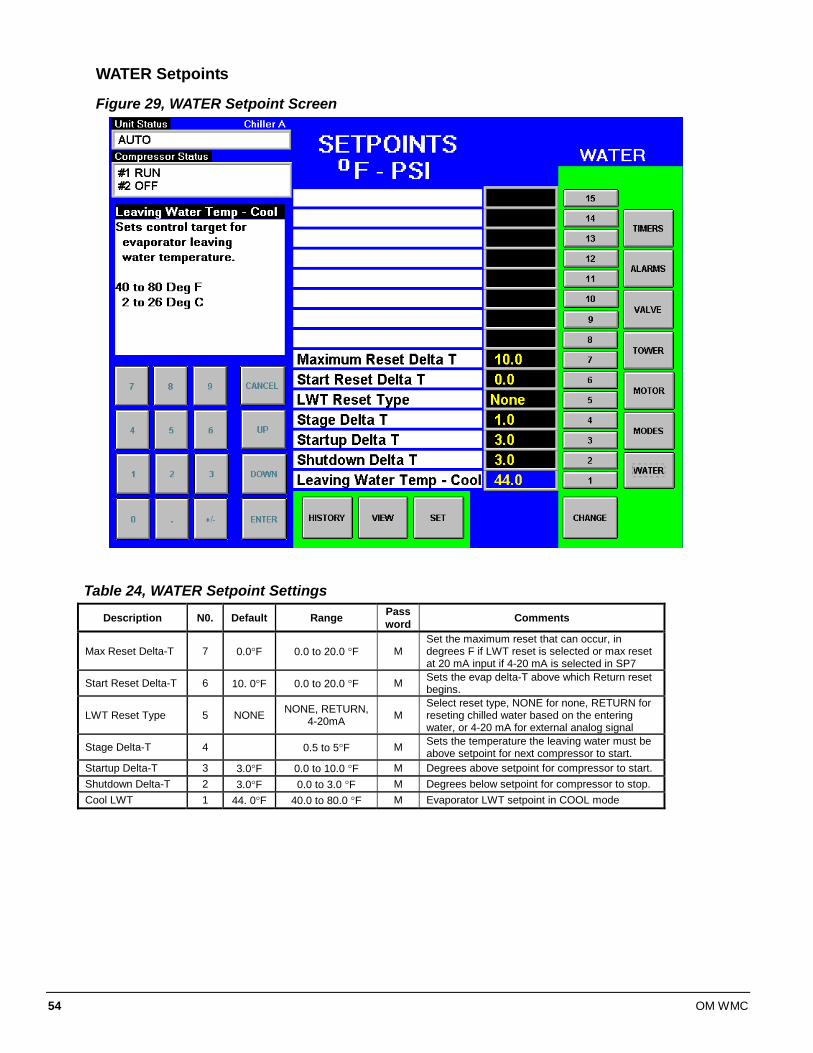
54 OM WMC
WATER Setpoints
Figure 29, WATER Setpoint Screen
Table 24, WATER Setpoint Settings
Description N0. Default Range Password Comments
Max Reset Delta-T 7 0.0°F 0.0 to 20.0 °F M Set the maximum reset that can occur, in degrees F if LWT reset is selected or max reset at 20 mA input if 4-20 mA is selected in SP7
Start Reset Delta-T 6 10. 0°F 0.0 to 20.0 °F M Sets the evap delta-T above which Return reset begins.
LWT Reset Type 5 NONE NONE, RETURN, 4-20mA M
Select reset type, NONE for none, RETURN for reseting chilled water based on the entering water, or 4-20 mA for external analog signal
Stage Delta-T 4 0.5 to 5°F M Sets the temperature the leaving water must be above setpoint for next compressor to start.
Startup Delta-T 3 3.0°F 0.0 to 10.0 °F M Degrees above setpoint for compressor to start. Shutdown Delta-T 2 3.0°F 0.0 to 3.0 °F M Degrees below setpoint for compressor to stop. Cool LWT 1 44. 0°F 40.0 to 80.0 °F M Evaporator LWT setpoint in COOL mode
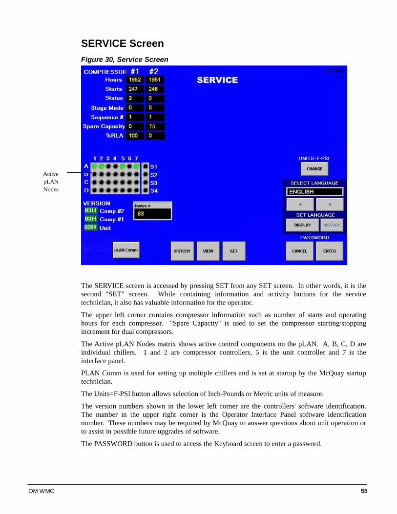
OM WMC 55
SERVICE Screen Figure 30, Service Screen
The SERVICE screen is accessed by pressing SET from any SET screen. In other words, it is the second "SET" screen. While containing information and activity buttons for the service technician, it also has valuable information for the operator.
The upper left corner contains compressor information such as number of starts and operating hours for each compressor. "Spare Capacity" is used to set the compressor starting/stopping increment for dual compressors.
The Active pLAN Nodes matrix shows active control components on the pLAN. A, B, C, D are individual chillers. 1 and 2 are compressor controllers, 5 is the unit controller and 7 is the interface panel.
PLAN Comm is used for setting up multiple chillers and is set at startup by the McQuay startup technician.
The Units=F-PSI button allows selection of Inch-Pounds or Metric units of measure.
The version numbers shown in the lower left corner are the controllers' software identification. The number in the upper right corner is the Operator Interface Panel software identification number. These numbers may be required by McQuay to answer questions about unit operation or to assist in possible future upgrades of software.
The PASSWORD button is used to access the Keyboard screen to enter a password.
Active pLAN Nodes
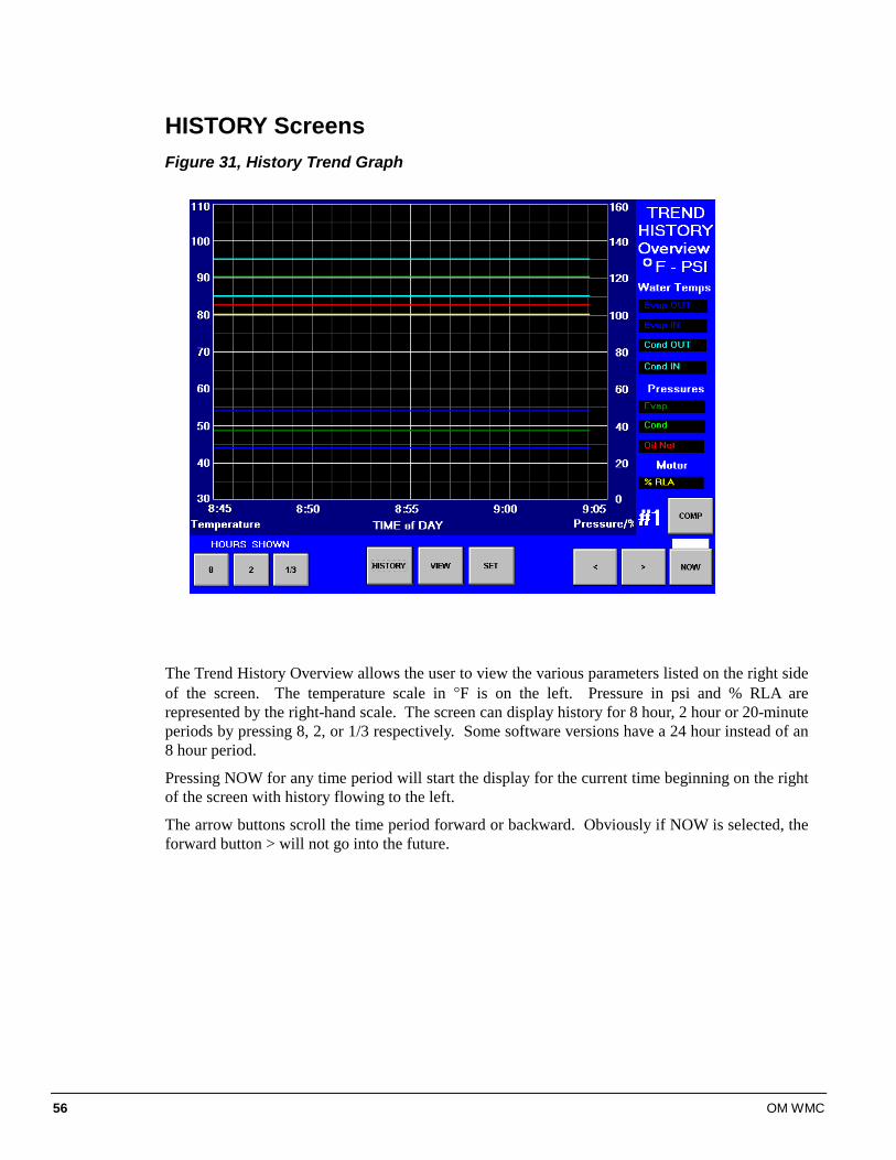
56 OM WMC
HISTORY Screens Figure 31, History Trend Graph
The Trend History Overview allows the user to view the various parameters listed on the right side of the screen. The temperature scale in °F is on the left. Pressure in psi and % RLA are represented by the right-hand scale. The screen can display history for 8 hour, 2 hour or 20-minute periods by pressing 8, 2, or 1/3 respectively. Some software versions have a 24 hour instead of an 8 hour period.
Pressing NOW for any time period will start the display for the current time beginning on the right of the screen with history flowing to the left.
The arrow buttons scroll the time period forward or backward. Obviously if NOW is selected, the forward button > will not go into the future.
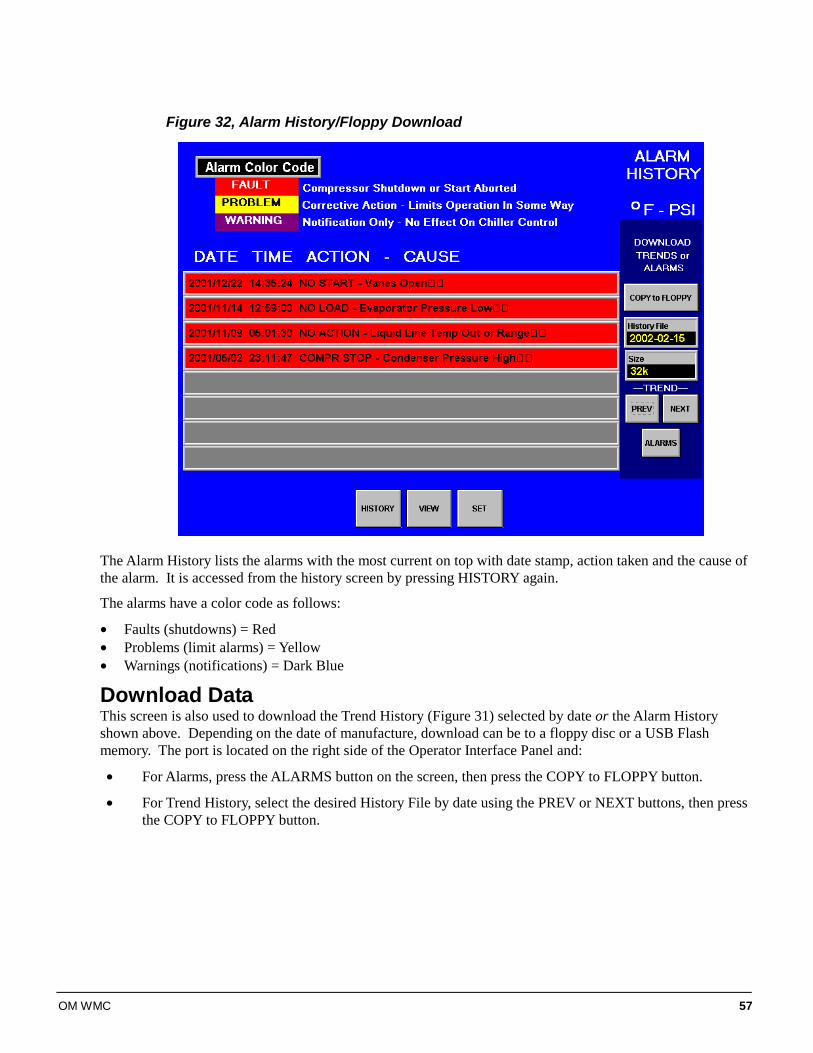
OM WMC 57
Figure 32, Alarm History/Floppy Download
The Alarm History lists the alarms with the most current on top with date stamp, action taken and the cause of the alarm. It is accessed from the history screen by pressing HISTORY again.
The alarms have a color code as follows:
• Faults (shutdowns) = Red • Problems (limit alarms) = Yellow • Warnings (notifications) = Dark Blue
Download Data This screen is also used to download the Trend History (Figure 31) selected by date or the Alarm History shown above. Depending on the date of manufacture, download can be to a floppy disc or a USB Flash memory. The port is located on the right side of the Operator Interface Panel and:
• For Alarms, press the ALARMS button on the screen, then press the COPY to FLOPPY button.
• For Trend History, select the desired History File by date using the PREV or NEXT buttons, then press the COPY to FLOPPY button.
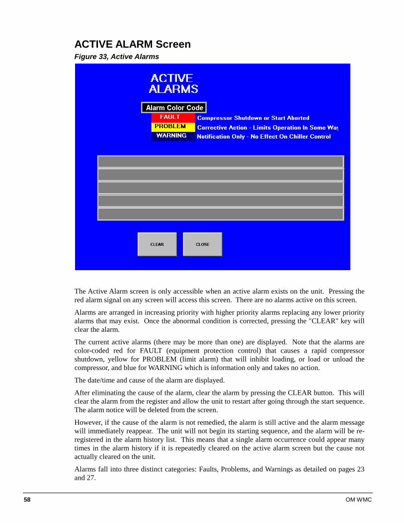
58 OM WMC
ACTIVE ALARM Screen Figure 33, Active Alarms
The Active Alarm screen is only accessible when an active alarm exists on the unit. Pressing the red alarm signal on any screen will access this screen. There are no alarms active on this screen.
Alarms are arranged in increasing priority with higher priority alarms replacing any lower priority alarms that may exist. Once the abnormal condition is corrected, pressing the "CLEAR" key will clear the alarm.
The current active alarms (there may be more than one) are displayed. Note that the alarms are color-coded red for FAULT (equipment protection control) that causes a rapid compressor shutdown, yellow for PROBLEM (limit alarm) that will inhibit loading, or load or unload the compressor, and blue for WARNING which is information only and takes no action.
The date/time and cause of the alarm are displayed.
After eliminating the cause of the alarm, clear the alarm by pressing the CLEAR button. This will clear the alarm from the register and allow the unit to restart after going through the start sequence. The alarm notice will be deleted from the screen.
However, if the cause of the alarm is not remedied, the alarm is still active and the alarm message will immediately reappear. The unit will not begin its starting sequence, and the alarm will be re-registered in the alarm history list. This means that a single alarm occurrence could appear many times in the alarm history if it is repeatedly cleared on the active alarm screen but the cause not actually cleared on the unit.
Alarms fall into three distinct categories: Faults, Problems, and Warnings as detailed on pages 23 and 27.
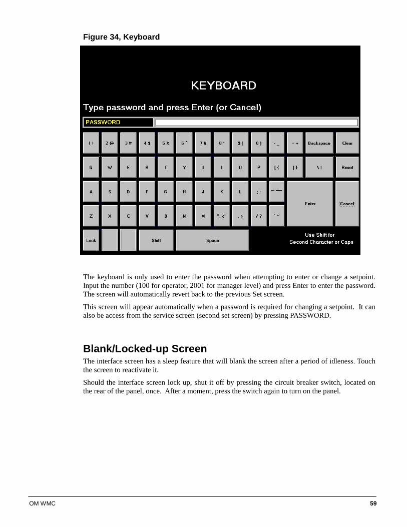
OM WMC 59
Figure 34, Keyboard
The keyboard is only used to enter the password when attempting to enter or change a setpoint. Input the number (100 for operator, 2001 for manager level) and press Enter to enter the password. The screen will automatically revert back to the previous Set screen.
This screen will appear automatically when a password is required for changing a setpoint. It can also be access from the service screen (second set screen) by pressing PASSWORD.
Blank/Locked-up Screen The interface screen has a sleep feature that will blank the screen after a period of idleness. Touch the screen to reactivate it.
Should the interface screen lock up, shut it off by pressing the circuit breaker switch, located on the rear of the panel, once. After a moment, press the switch again to turn on the panel.
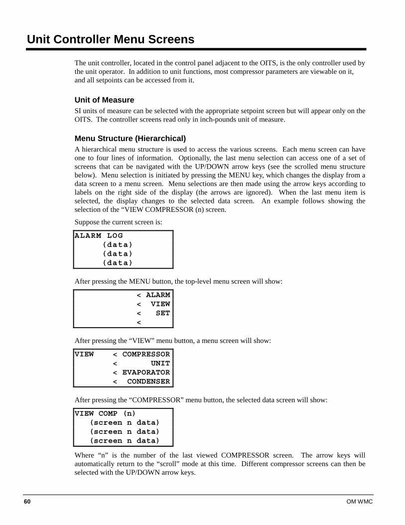
60 OM WMC
Unit Controller Menu Screens
The unit controller, located in the control panel adjacent to the OITS, is the only controller used by the unit operator. In addition to unit functions, most compressor parameters are viewable on it, and all setpoints can be accessed from it.
Unit of Measure SI units of measure can be selected with the appropriate setpoint screen but will appear only on the OITS. The controller screens read only in inch-pounds unit of measure.
Menu Structure (Hierarchical) A hierarchical menu structure is used to access the various screens. Each menu screen can have one to four lines of information. Optionally, the last menu selection can access one of a set of screens that can be navigated with the UP/DOWN arrow keys (see the scrolled menu structure below). Menu selection is initiated by pressing the MENU key, which changes the display from a data screen to a menu screen. Menu selections are then made using the arrow keys according to labels on the right side of the display (the arrows are ignored). When the last menu item is selected, the display changes to the selected data screen. An example follows showing the selection of the “VIEW COMPRESSOR (n) screen.
Suppose the current screen is:
ALARM LOG(data)(data)(data)
After pressing the MENU button, the top-level menu screen will show:
< ALARM< VIEW< SET<
After pressing the “VIEW” menu button, a menu screen will show:
VIEW < COMPRESSOR< UNIT< EVAPORATOR< CONDENSER
After pressing the “COMPRESSOR” menu button, the selected data screen will show:
VIEW COMP (n)(screen n data)(screen n data)(screen n data)
Where “n” is the number of the last viewed COMPRESSOR screen. The arrow keys will automatically return to the “scroll” mode at this time. Different compressor screens can then be selected with the UP/DOWN arrow keys.
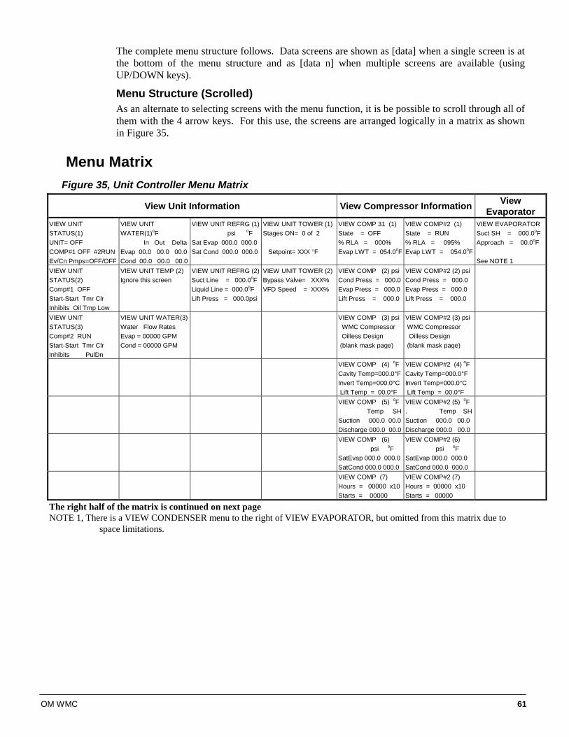
OM WMC 61
The complete menu structure follows. Data screens are shown as [data] when a single screen is at the bottom of the menu structure and as [data n] when multiple screens are available (using UP/DOWN keys).
Menu Structure (Scrolled) As an alternate to selecting screens with the menu function, it is be possible to scroll through all of them with the 4 arrow keys. For this use, the screens are arranged logically in a matrix as shown in Figure 35.
Menu Matrix Figure 35, Unit Controller Menu Matrix
View Unit Information View Compressor Information View Evaporator
VIEW UNIT STATUS(1) UNIT= OFF COMP#1 OFF #2RUN Ev/Cn Pmps=OFF/OFF
VIEW UNIT WATER(1)oF In Out Delta Evap 00.0 00.0 00.0 Cond 00.0 00.0 00.0
VIEW UNIT REFRG (1) psi oF Sat Evap 000.0 000.0 Sat Cond 000.0 000.0
VIEW UNIT TOWER (1) Stages ON= 0 of 2 Setpoint= XXX °F
VIEW COMP 31 (1) State = OFF % RLA = 000% Evap LWT = 054.0oF
VIEW COMP#2 (1) State = RUN % RLA = 095% Evap LWT = 054.0oF
VIEW EVAPORATOR Suct SH = 000.0oF Approach = 00.0oF See NOTE 1
VIEW UNIT STATUS(2) Comp#1 OFF Start-Start Tmr Clr Inhibits Oil Tmp Low
VIEW UNIT TEMP (2) Ignore this screen
VIEW UNIT REFRG (2)Suct Line = 000.0oF Liquid Line = 000.0oF Lift Press = 000.0psi
VIEW UNIT TOWER (2) Bypass Valve= XXX% VFD Speed = XXX%
VIEW COMP (2) psi Cond Press = 000.0 Evap Press = 000.0 Lift Press = 000.0
VIEW COMP#2 (2) psi Cond Press = 000.0 Evap Press = 000.0 Lift Press = 000.0
VIEW UNIT STATUS(3) Comp#2 RUN Start-Start Tmr Clr Inhibits PulDn
VIEW UNIT WATER(3) Water Flow Rates Evap = 00000 GPM Cond = 00000 GPM
VIEW COMP (3) psi WMC Compressor Oilless Design (blank mask page)
VIEW COMP#2 (3) psi WMC Compressor Oilless Design (blank mask page)
VIEW COMP (4) oF Cavity Temp=000.0°F Invert Temp=000.0°C Lift Temp = 00.0°F
VIEW COMP#2 (4) oF Cavity Temp=000.0°F Invert Temp=000.0°C Lift Temp = 00.0°F
VIEW COMP (5) oF Temp SH Suction 000.0 00.0 Discharge 000.0 00.0
VIEW COMP#2 (5) oF . Temp SHSuction 000.0 00.0 Discharge 000.0 00.0
VIEW COMP (6) psi oF SatEvap 000.0 000.0 SatCond 000.0 000.0
VIEW COMP#2 (6) psi oF SatEvap 000.0 000.0 SatCond 000.0 000.0
VIEW COMP (7) Hours = 00000 x10 Starts = 00000
VIEW COMP#2 (7) Hours = 00000 x10 Starts = 00000
The right half of the matrix is continued on next page NOTE 1, There is a VIEW CONDENSER menu to the right of VIEW EVAPORATOR, but omitted from this matrix due to
space limitations.

62 OM WMC
Table Continued VIEW ALARMS SET SETPOINTS PASSWORD Alarm Log: 01 description HH:MM:SS MM/DD/YY
SET UNIT SPs (1) Unit Enable = OFF Unit Mode = COOL Source = SWITCHES
SET COMP#1 SPs (1) Demand Limit=OFF Minimum Amps=040% Maximum Amps=100%
SET COMP#2 SPs (1) Demand Limit=OFF Minimum Amps=040% Maximum Amps=100%
SET ALARM LMTs (1) LowEvPrHold=33psi LowEvPrUnld=31psi LowEvPrStop=29psi
SET TOWER SPs (1) TowerControl=(type?) Tower Stages=4 StageUP/Dn=080/020
SET PASSWORD Enter Password:00000 No Access Given
Alarm Log: 02 description HH:MM:SS MM/DD/YY .
SET UNIT SPs (2) Available Modes = COOL Select w/Unit Off
SET COMP SPs (2) StageMode =Normal StageSequence# = 01 Max Compr ON = 01
SET COMP#2 SPs (2) StageMode =Normal StageSequence# = 01 Max Compr ON = 01
SET ALARM LMTs (2) HighCondPr =140psi HiDschT-Load=170oF HiDschT-Stop=190oF
SET TOWER SPs (2) Stage ON #1 #2 #3 #4 xxx xxx xxx xxx
SET PASSWORD (2)Tech Password 00000 00000 No Access Given
Alarm Log: 03 to 25 description HH:MM:SS MM/DD/YY
SET UNIT SPs (3) Cool LWT = 44.0°F
SET COMP SPs (3) StageDeltaT = 1.0oF Stop-Start = 03 min Start-Start = 40 min
SET COMP#2 SPs (3) StageDeltaT = 1.0oF Stop-Start = 03 min Start-Start = 40 min
SET ALARM LMTs (3) WMC Compressor Oilless Design (blank mask page)
SET TOWER SPs (3) StageDiff= (type?) StageUp = 02 min StageDown=05 min
SET UNIT SPs (4) Leaving Water Temp StartDelta = 3.0°F StopDelta = 3.0°F
SET COMP SPs (4) Full Load = 300 sec Name Plate RLA 085
SET COMP#2 SPs (4) Full Load = 300 sec
SET ALARM LMTs (4) Surge Slp Str=20oF Surge Tmp Run=06oF MtrCurThrshld=10%
SET TOWER SPs (4) Valve/VFD Control= None Valve Type=NC
SET UNIT SPs (5) Rest Type = NONE MaxResetDT =00.0oF StrtResetDT = 10.0oF
SET COMP SPs (5) Nom Capacity = 0100T HotGasBypass = 30%
SET COMP#2 SPs (5) Nom Capacity = 0100T HotGasBypass = 30%
SET ALARM LMTs (5) Evap Freeze= 34.0°F Cond Freeze= 34.0°F
SET TOWER SPs (5) Valve Sp= (type?) Valve DB= (type?)
SET UNIT SPs (6) Soft Load = OFF BeginAmpLimit= 040% SoftLoadRamp=05min
SET COMP SPs (6) InterLokTmr= 010sec UnloadTimer = 030 sec
SET COMP#2 SPs (6) UnloadTimer = 060 sec PostlubeTmr = 030 sec
SET TOWER SPs (6) ValveStartPosition Min=010% @ 060oF Max=090% @ 090oF
Alarm Log: 25 description HH:MM:SS MM/DD/YY
SET UNIT SPs (7) Max/Min LWT Rates Max = 0.5oF/min Min = 0.1oF/min
SET COMP SPs (7) WMC Automatic Vane Control (blank mask page)
SET COMP SPs (7) WMC Automatic Vane Control (blank mask page)
SET TOWER SPs (7) Valve Control Range Min = 010% Max = 090%
SET UNIT SPs (8) EvapRecTmr = 0.5min EvapPump = #1 ONLY CondPump = #1 ONLY
SET COMP SPs (8) MAX KW = 76.0 Lag Start = 000Sec Step Down = 060Sec
SET COMP SPs (8) MAX KW = 76.0 Lag Start = 000Sec Step Down = 060Sec
SET TOWER SPs (8 PD Control Loop Error Gain = 25 Slope Gain = 25
SET UNIT SPs (9) Templifier Src Water No Start = 070oF Delta Reset = 055oF Ignore this menu
SET COMP SPs (9) Protocol =M-BUS MSTR Ident Number= 001 Baud Rate = 19200
SET COMP SPs (9) Protocol =M-BUS MSTR Ident Number= 001 Baud Rate = 19200
SET UNIT SPs (10) VFD = YES Min Speed =015%-KW Max Kw = 076.0 Ignore this menu
SET COMP SPs (10) Refrg Sat Pressure Evp Offset =+00.0 psi Cnd Offset = +00.0psi
SET COMP#2 SPs (10) Refrg Sat Pressure Evp Offset =+00.0 psi Cnd Offset = +00.0psi
SET UNIT SPs (11) Max Wtr Flow Rates Evap WF=02400GPM CondWF=03000GPM
SET COMP SPs (11) ELWT Offset = +0.0 oF
SET COMP#2 SPs (11) ELWT Offset = +0.0 oF
SET UNIT SPs (12) Time Day/Mon/Yr 24 hr time day of wk
SET UNIT SPs (13) Display Format Units = oF/psi (IP) Lang = English
SET UNIT SPs (14) Protocol = MODBUS Id #= 001 Units =IP Baud Rate = 19200
SET UNIT SPs (15) Ex-Val Std Values Pos 450% L76.0psi Enthalpy Sp 85.0°F Ignore this menu
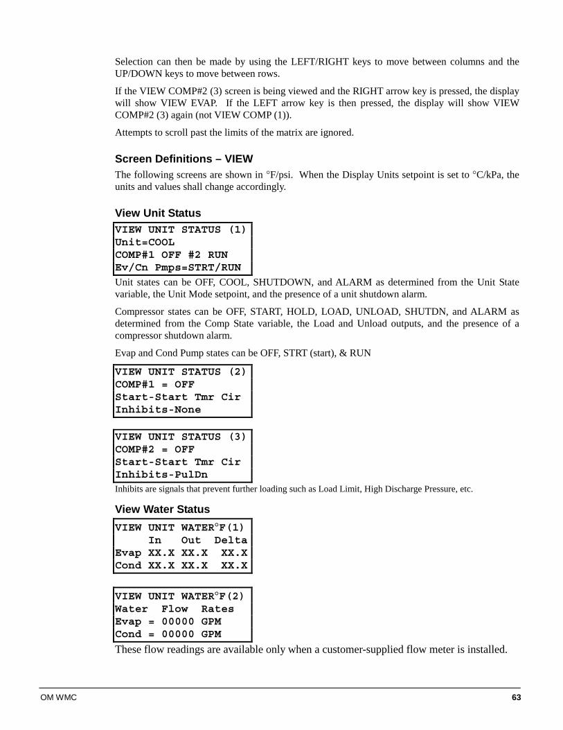
OM WMC 63
Selection can then be made by using the LEFT/RIGHT keys to move between columns and the UP/DOWN keys to move between rows.
If the VIEW COMP#2 (3) screen is being viewed and the RIGHT arrow key is pressed, the display will show VIEW EVAP. If the LEFT arrow key is then pressed, the display will show VIEW COMP#2 (3) again (not VIEW COMP (1)).
Attempts to scroll past the limits of the matrix are ignored.
Screen Definitions – VIEW The following screens are shown in °F/psi. When the Display Units setpoint is set to °C/kPa, the units and values shall change accordingly.
View Unit Status VIEW UNIT STATUS (1)Unit=COOLCOMP#1 OFF #2 RUNEv/Cn Pmps=STRT/RUN
Unit states can be OFF, COOL, SHUTDOWN, and ALARM as determined from the Unit State variable, the Unit Mode setpoint, and the presence of a unit shutdown alarm.
Compressor states can be OFF, START, HOLD, LOAD, UNLOAD, SHUTDN, and ALARM as determined from the Comp State variable, the Load and Unload outputs, and the presence of a compressor shutdown alarm.
Evap and Cond Pump states can be OFF, STRT (start), & RUN
VIEW UNIT STATUS (2)COMP#1 = OFFStart-Start Tmr CirInhibits-None VIEW UNIT STATUS (3)COMP#2 = OFFStart-Start Tmr CirInhibits-PulDnInhibits are signals that prevent further loading such as Load Limit, High Discharge Pressure, etc.
View Water Status VIEW UNIT WATER°F(1)
In Out DeltaEvap XX.X XX.X XX.XCond XX.X XX.X XX.X
VIEW UNIT WATER°F(2)Water Flow RatesEvap = 00000 GPMCond = 00000 GPM
These flow readings are available only when a customer-supplied flow meter is installed.
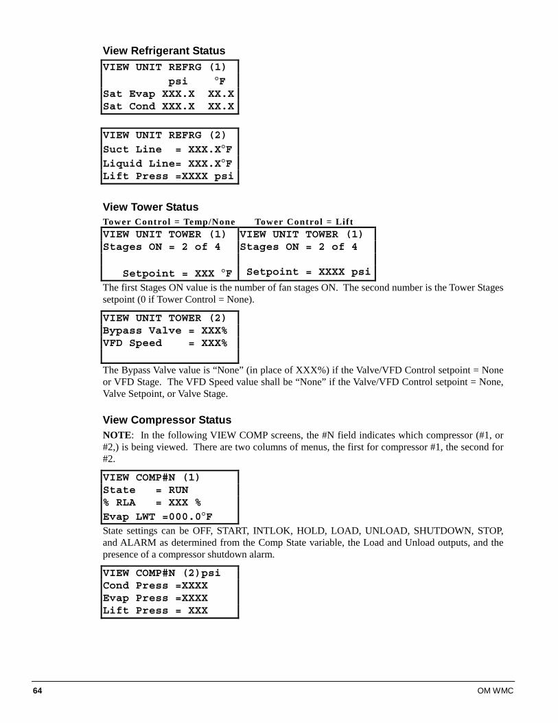
64 OM WMC
View Refrigerant Status VIEW UNIT REFRG (1)
psi °FSat Evap XXX.X XX.XSat Cond XXX.X XX.X
VIEW UNIT REFRG (2)Suct Line = XXX.X°FLiquid Line= XXX.X°FLift Press =XXXX psi
View Tower Status Tower Control = Temp/None Tower Control = Lift VIEW UNIT TOWER (1) VIEW UNIT TOWER (1)Stages ON = 2 of 4 Stages ON = 2 of 4
Setpoint = XXX °F Setpoint = XXXX psi
The first Stages ON value is the number of fan stages ON. The second number is the Tower Stages setpoint (0 if Tower Control = None).
VIEW UNIT TOWER (2)Bypass Valve = XXX%VFD Speed = XXX%
The Bypass Valve value is “None” (in place of XXX%) if the Valve/VFD Control setpoint = None or VFD Stage. The VFD Speed value shall be “None” if the Valve/VFD Control setpoint = None, Valve Setpoint, or Valve Stage.
View Compressor Status NOTE: In the following VIEW COMP screens, the #N field indicates which compressor (#1, or #2,) is being viewed. There are two columns of menus, the first for compressor #1, the second for #2.
VIEW COMP#N (1)State = RUN% RLA = XXX %Evap LWT =000.0°FState settings can be OFF, START, INTLOK, HOLD, LOAD, UNLOAD, SHUTDOWN, STOP, and ALARM as determined from the Comp State variable, the Load and Unload outputs, and the presence of a compressor shutdown alarm.
VIEW COMP#N (2)psiCond Press =XXXXEvap Press =XXXXLift Press = XXX
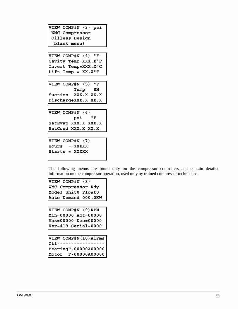
OM WMC 65
VIEW COMP#N (3) psiWMC CompressorOilless Design(blank menu)
VIEW COMP#N (4) °FCavity Temp=XXX.X°FInvert Temp=XXX.X°CLift Temp = XX.X°F
VIEW COMP#N (5) °F
Temp SHSuction XXX.X XX.XDischargeXXX.X XX.X
VIEW COMP#N (6)
psi °FSatEvap XXX.X XXX.XSatCond XXX.X XX.X
VIEW COMP#N (7)Hours = XXXXXStarts = XXXXX
The following menus are found only on the compressor controllers and contain detailed information on the compressor operation, used only by trained compressor technicians.
VIEW COMP#N (8)WMC Compressor Rdy Mode3 Unit0 Float0Auto Demand 000.0KW
VIEW COMP#N (9)RPMMin=00000 Act=00000Max=00000 Des=00000Ver=419 Serial=0000
VIEW COMP#N(10)AlrmsCtl-----------------BearingF-00000A00000Motor F-00000A00000
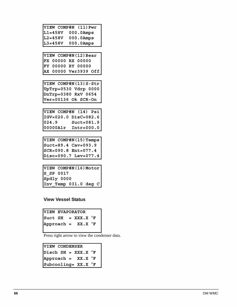
66 OM WMC
VIEW COMP#N (11)PwrL1=458V 000.0AmpsL2=458V 000.0AmpsL3=458V 000.0Amps
VIEW COMP#N(12)BearFX 00000 RX 00000FY 00000 RY 00000AX 00000 Ver3939 Off
VIEW COMP#N(13)S-StrUpTrp=0530 Vdrp 0000DnTrp=0380 RxV 0654Ver=00136 Ok SCR-On
VIEW COMP#N (14) PsiIGV=020.0 DisC=082.6024.9 Suct=081.900000Alr Intr=000.0
VIEW COMP#N(15)TempsSuct=89.4 Cav=093.9SCR=090.8 Ent=077.4Disc=090.7 Lev=077.4
VIEW COMP#N(16)MotorS_SP 0017Spdly 0000Inv_Temp 031.0 deg C
View Vessel Status VIEW EVAPORATORSuct SH = XXX.X °FApproach = XX.X °F
Press right arrow to view the condenser data.
VIEW CONDENSERDisch SH = XXX.X °FApproach = XX.X °FSubcooling= XX.X °F
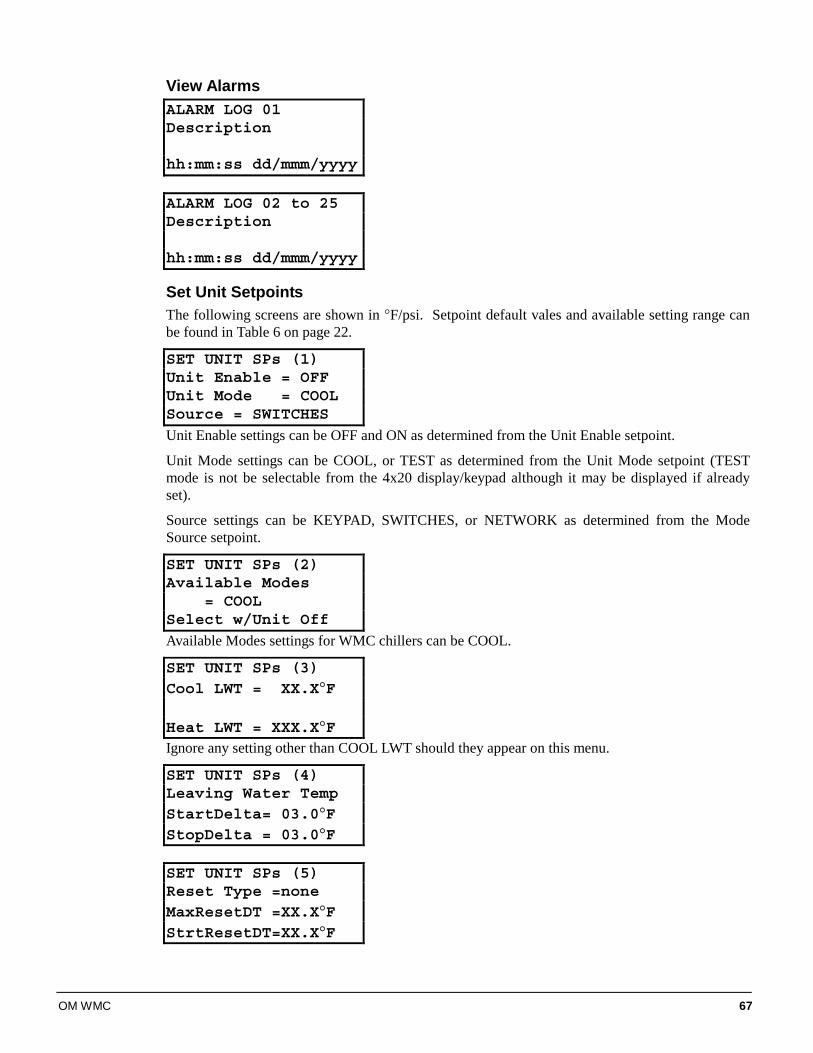
OM WMC 67
View Alarms ALARM LOG 01Description
hh:mm:ss dd/mmm/yyyy ALARM LOG 02 to 25Description
hh:mm:ss dd/mmm/yyyy
Set Unit Setpoints The following screens are shown in °F/psi. Setpoint default vales and available setting range can be found in Table 6 on page 22.
SET UNIT SPs (1)Unit Enable = OFFUnit Mode = COOLSource = SWITCHES Unit Enable settings can be OFF and ON as determined from the Unit Enable setpoint.
Unit Mode settings can be COOL, or TEST as determined from the Unit Mode setpoint (TEST mode is not be selectable from the 4x20 display/keypad although it may be displayed if already set).
Source settings can be KEYPAD, SWITCHES, or NETWORK as determined from the Mode Source setpoint.
SET UNIT SPs (2)Available Modes
= COOLSelect w/Unit Off
Available Modes settings for WMC chillers can be COOL.
SET UNIT SPs (3)Cool LWT = XX.X°F
Heat LWT = XXX.X°FIgnore any setting other than COOL LWT should they appear on this menu.
SET UNIT SPs (4)Leaving Water TempStartDelta= 03.0°FStopDelta = 03.0°F SET UNIT SPs (5)Reset Type =noneMaxResetDT =XX.X°FStrtResetDT=XX.X°F
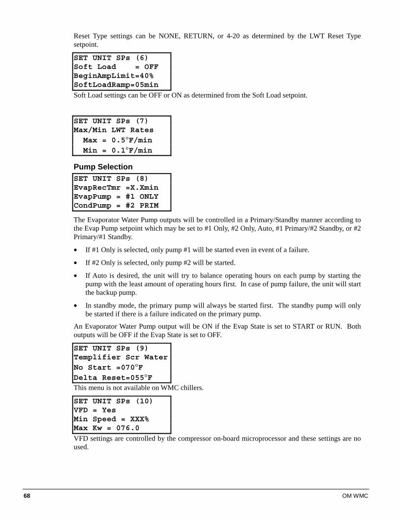
68 OM WMC
Reset Type settings can be NONE, RETURN, or 4-20 as determined by the LWT Reset Type setpoint.
SET UNIT SPs (6)Soft Load = OFFBeginAmpLimit=40%SoftLoadRamp=05min
Soft Load settings can be OFF or ON as determined from the Soft Load setpoint.
SET UNIT SPs (7)Max/Min LWT Rates
Max = 0.5°F/minMin = 0.1°F/min
Pump Selection SET UNIT SPs (8)EvapRecTmr =X.XminEvapPump = #1 ONLYCondPump = #2 PRIM
The Evaporator Water Pump outputs will be controlled in a Primary/Standby manner according to the Evap Pump setpoint which may be set to #1 Only, #2 Only, Auto, #1 Primary/#2 Standby, or #2 Primary/#1 Standby.
• If #1 Only is selected, only pump #1 will be started even in event of a failure.
• If #2 Only is selected, only pump #2 will be started.
• If Auto is desired, the unit will try to balance operating hours on each pump by starting the pump with the least amount of operating hours first. In case of pump failure, the unit will start the backup pump.
• In standby mode, the primary pump will always be started first. The standby pump will only be started if there is a failure indicated on the primary pump.
An Evaporator Water Pump output will be ON if the Evap State is set to START or RUN. Both outputs will be OFF if the Evap State is set to OFF.
SET UNIT SPs (9)Templifier Scr WaterNo Start =070°FDelta Reset=055°FThis menu is not available on WMC chillers.
SET UNIT SPs (10)VFD = YesMin Speed = XXX%Max Kw = 076.0
VFD settings are controlled by the compressor on-board microprocessor and these settings are no used.
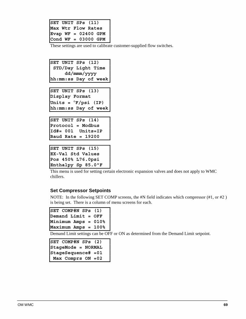
OM WMC 69
SET UNIT SPs (11)Max Wtr Flow RatesEvap WF = 02400 GPMCond WF = 03000 GPM
These settings are used to calibrate customer-supplied flow switches.
SET UNIT SPs (12)STD/Day Light Time
dd/mmm/yyyyhh:mm:ss Day of week SET UNIT SPs (13)Display FormatUnits = °F/psi (IP)hh:mm:ss Day of week SET UNIT SPs (14)Protocol = ModbusId#= 001 Units=IPBaud Rate = 19200 SET UNIT SPs (15)EX-Val Std ValuesPos 450% L76.0psiEnthalpy Sp 85.0°F
This menu is used for setting certain electronic expansion valves and does not apply to WMC chillers.
Set Compressor Setpoints NOTE: In the following SET COMP screens, the #N field indicates which compressor (#1, or #2 ) is being set. There is a column of menu screens for each.
SET COMP#N SPs (1)Demand Limit = OFFMinimum Amps = 010%Maximum Amps = 100%
Demand Limit settings can be OFF or ON as determined from the Demand Limit setpoint.
SET COMP#N SPs (2)StageMode = NORMALStageSequence# =01Max Comprs ON =02
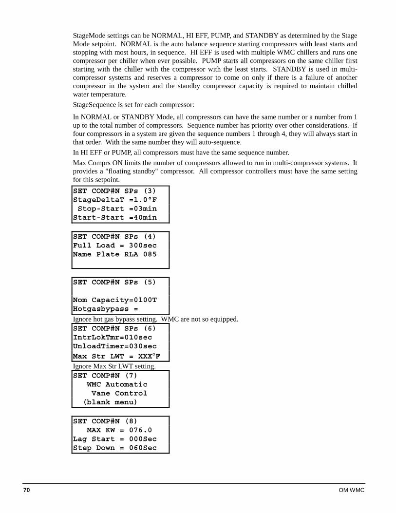
70 OM WMC
StageMode settings can be NORMAL, HI EFF, PUMP, and STANDBY as determined by the Stage Mode setpoint. NORMAL is the auto balance sequence starting compressors with least starts and stopping with most hours, in sequence. HI EFF is used with multiple WMC chillers and runs one compressor per chiller when ever possible. PUMP starts all compressors on the same chiller first starting with the chiller with the compressor with the least starts. STANDBY is used in multi-compressor systems and reserves a compressor to come on only if there is a failure of another compressor in the system and the standby compressor capacity is required to maintain chilled water temperature. StageSequence is set for each compressor:
In NORMAL or STANDBY Mode, all compressors can have the same number or a number from 1 up to the total number of compressors. Sequence number has priority over other considerations. If four compressors in a system are given the sequence numbers 1 through 4, they will always start in that order. With the same number they will auto-sequence. In HI EFF or PUMP, all compressors must have the same sequence number. Max Comprs ON limits the number of compressors allowed to run in multi-compressor systems. It provides a "floating standby" compressor. All compressor controllers must have the same setting for this setpoint. SET COMP#N SPs (3)StageDeltaT =1.0°FStop-Start =03minStart-Start =40min SET COMP#N SPs (4)Full Load = 300secName Plate RLA 085
SET COMP#N SPs (5)
Nom Capacity=0100THotgasbypass =
Ignore hot gas bypass setting. WMC are not so equipped. SET COMP#N SPs (6)IntrLokTmr=010sec UnloadTimer=030secMax Str LWT = XXX°FIgnore Max Str LWT setting. SET COMP#N (7)
WMC AutomaticVane Control
(blank menu) SET COMP#N (8)
MAX KW = 076.0Lag Start = 000SecStep Down = 060Sec
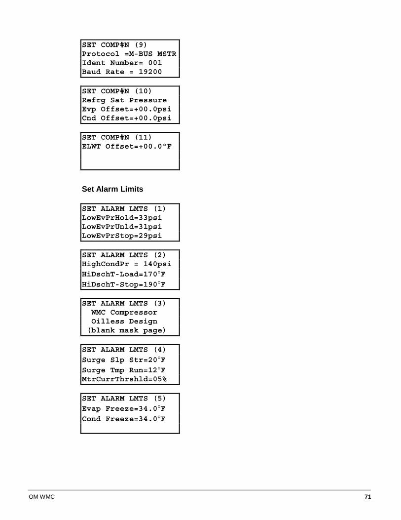
OM WMC 71
SET COMP#N (9)Protocol =M-BUS MSTRIdent Number= 001Baud Rate = 19200 SET COMP#N (10)Refrg Sat PressureEvp Offset=+00.0psiCnd Offset=+00.0psi SET COMP#N (11)ELWT Offset=+00.0°F
Set Alarm Limits SET ALARM LMTS (1)LowEvPrHold=33psiLowEvPrUnld=31psiLowEvPrStop=29psi SET ALARM LMTS (2)HighCondPr = 140psiHiDschT-Load=170°FHiDschT-Stop=190°F SET ALARM LMTS (3)
WMC CompressorOilless Design(blank mask page)
SET ALARM LMTS (4)Surge Slp Str=20°FSurge Tmp Run=12°FMtrCurrThrshld=05% SET ALARM LMTS (5)Evap Freeze=34.0°FCond Freeze=34.0°F
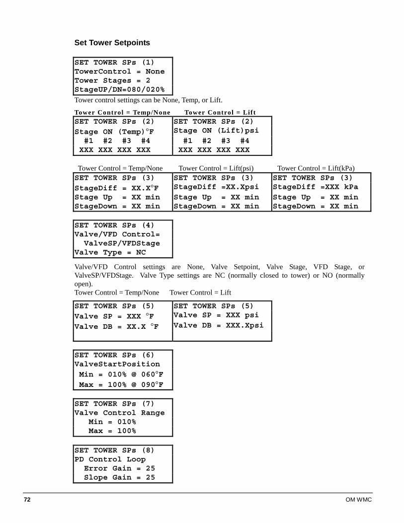
72 OM WMC
Set Tower Setpoints SET TOWER SPs (1)TowerControl = NoneTower Stages = 2StageUP/DN=080/020%
Tower control settings can be None, Temp, or Lift.
Tower Control = Temp/None Tower Control = Lift SET TOWER SPs (2) SET TOWER SPs (2)Stage ON (Temp)°F Stage ON (Lift)psi
#1 #2 #3 #4 #1 #2 #3 #4XXX XXX XXX XXX XXX XXX XXX XXX
Tower Control = Temp/None Tower Control = Lift(psi) Tower Control = Lift(kPa) SET TOWER SPs (3) SET TOWER SPs (3) SET TOWER SPs (3)StageDiff = XX.X°F StageDiff =XX.Xpsi StageDiff =XXX kPaStage Up = XX min Stage Up = XX min Stage Up = XX minStageDown = XX min StageDown = XX min StageDown = XX min SET TOWER SPs (4)Valve/VFD Control=
ValveSP/VFDStageValve Type = NC
Valve/VFD Control settings are None, Valve Setpoint, Valve Stage, VFD Stage, or ValveSP/VFDStage. Valve Type settings are NC (normally closed to tower) or NO (normally open). Tower Control = Temp/None Tower Control = Lift
SET TOWER SPs (5) SET TOWER SPs (5)Valve SP = XXX °F Valve SP = XXX psi
Valve DB = XX.X °F Valve DB = XXX.Xpsi
SET TOWER SPs (6)ValveStartPositionMin = 010% @ 060°FMax = 100% @ 090°F
SET TOWER SPs (7)Valve Control Range
Min = 010%Max = 100%
SET TOWER SPs (8)PD Control Loop
Error Gain = 25Slope Gain = 25
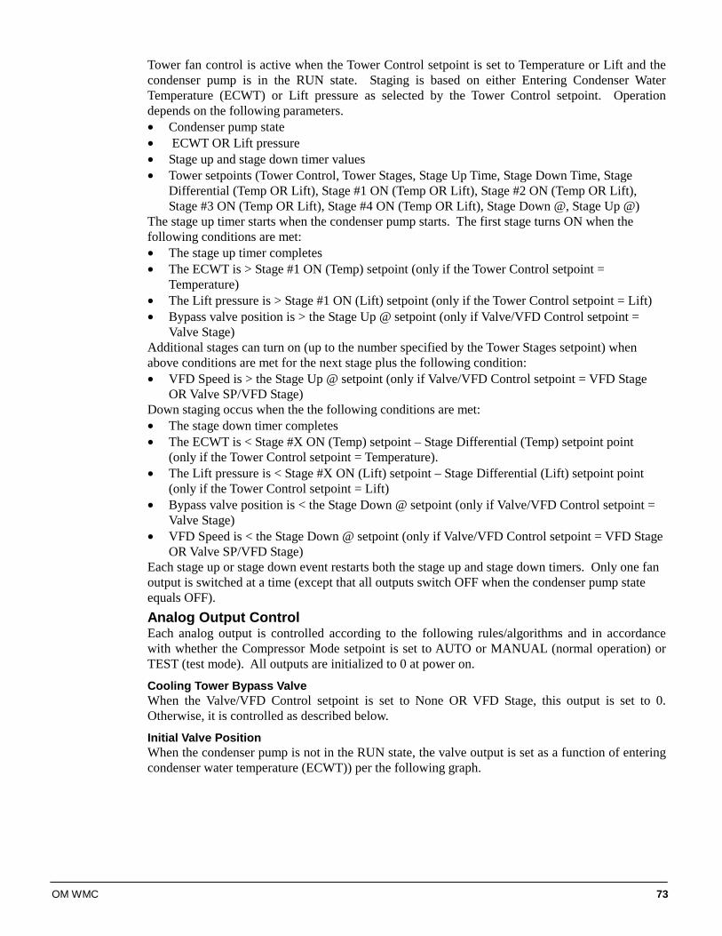
OM WMC 73
Tower fan control is active when the Tower Control setpoint is set to Temperature or Lift and the condenser pump is in the RUN state. Staging is based on either Entering Condenser Water Temperature (ECWT) or Lift pressure as selected by the Tower Control setpoint. Operation depends on the following parameters. • Condenser pump state • ECWT OR Lift pressure • Stage up and stage down timer values • Tower setpoints (Tower Control, Tower Stages, Stage Up Time, Stage Down Time, Stage
Differential (Temp OR Lift), Stage #1 ON (Temp OR Lift), Stage #2 ON (Temp OR Lift), Stage #3 ON (Temp OR Lift), Stage #4 ON (Temp OR Lift), Stage Down @, Stage Up @)
The stage up timer starts when the condenser pump starts. The first stage turns ON when the following conditions are met: • The stage up timer completes • The ECWT is > Stage #1 ON (Temp) setpoint (only if the Tower Control setpoint =
Temperature) • The Lift pressure is > Stage #1 ON (Lift) setpoint (only if the Tower Control setpoint = Lift) • Bypass valve position is > the Stage Up @ setpoint (only if Valve/VFD Control setpoint =
Valve Stage) Additional stages can turn on (up to the number specified by the Tower Stages setpoint) when above conditions are met for the next stage plus the following condition: • VFD Speed is > the Stage Up @ setpoint (only if Valve/VFD Control setpoint = VFD Stage
OR Valve SP/VFD Stage) Down staging occus when the the following conditions are met: • The stage down timer completes • The ECWT is < Stage #X ON (Temp) setpoint – Stage Differential (Temp) setpoint point
(only if the Tower Control setpoint = Temperature). • The Lift pressure is < Stage #X ON (Lift) setpoint – Stage Differential (Lift) setpoint point
(only if the Tower Control setpoint = Lift) • Bypass valve position is < the Stage Down @ setpoint (only if Valve/VFD Control setpoint =
Valve Stage) • VFD Speed is < the Stage Down @ setpoint (only if Valve/VFD Control setpoint = VFD Stage
OR Valve SP/VFD Stage) Each stage up or stage down event restarts both the stage up and stage down timers. Only one fan output is switched at a time (except that all outputs switch OFF when the condenser pump state equals OFF). Analog Output Control Each analog output is controlled according to the following rules/algorithms and in accordance with whether the Compressor Mode setpoint is set to AUTO or MANUAL (normal operation) or TEST (test mode). All outputs are initialized to 0 at power on.
Cooling Tower Bypass Valve When the Valve/VFD Control setpoint is set to None OR VFD Stage, this output is set to 0. Otherwise, it is controlled as described below.
Initial Valve Position When the condenser pump is not in the RUN state, the valve output is set as a function of entering condenser water temperature (ECWT)) per the following graph.
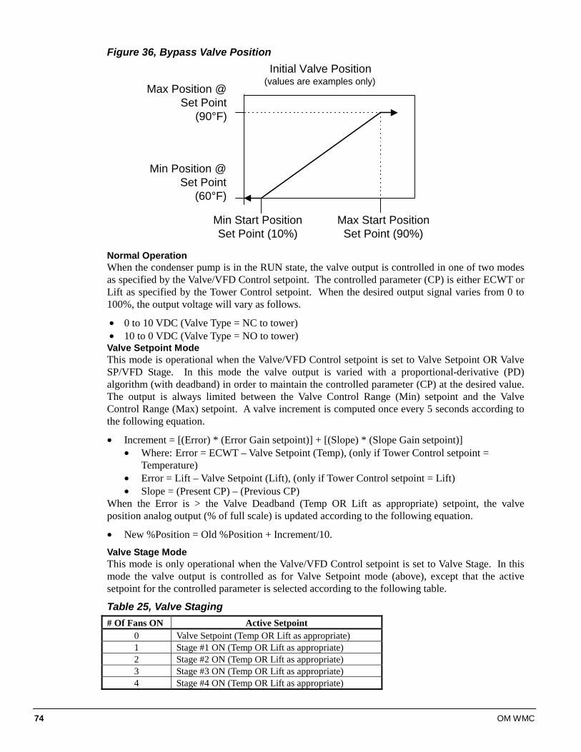
74 OM WMC
Figure 36, Bypass Valve Position
Max Position @Set Point
(90°F)
Min Position @Set Point
(60°F)
Min Start PositionSet Point (10%)
Initial Valve Position(values are examples only)
Max Start PositionSet Point (90%)
Normal Operation When the condenser pump is in the RUN state, the valve output is controlled in one of two modes as specified by the Valve/VFD Control setpoint. The controlled parameter (CP) is either ECWT or Lift as specified by the Tower Control setpoint. When the desired output signal varies from 0 to 100%, the output voltage will vary as follows.
• 0 to 10 VDC (Valve Type = NC to tower) • 10 to 0 VDC (Valve Type = NO to tower) Valve Setpoint Mode This mode is operational when the Valve/VFD Control setpoint is set to Valve Setpoint OR Valve SP/VFD Stage. In this mode the valve output is varied with a proportional-derivative (PD) algorithm (with deadband) in order to maintain the controlled parameter (CP) at the desired value. The output is always limited between the Valve Control Range (Min) setpoint and the Valve Control Range (Max) setpoint. A valve increment is computed once every 5 seconds according to the following equation.
• Increment = [(Error) * (Error Gain setpoint)] + [(Slope) * (Slope Gain setpoint)] • Where: Error = ECWT – Valve Setpoint (Temp), (only if Tower Control setpoint =
Temperature) • Error = Lift – Valve Setpoint (Lift), (only if Tower Control setpoint = Lift) • Slope = (Present CP) – (Previous CP)
When the Error is > the Valve Deadband (Temp OR Lift as appropriate) setpoint, the valve position analog output (% of full scale) is updated according to the following equation.
• New %Position = Old %Position + Increment/10.
Valve Stage Mode This mode is only operational when the Valve/VFD Control setpoint is set to Valve Stage. In this mode the valve output is controlled as for Valve Setpoint mode (above), except that the active setpoint for the controlled parameter is selected according to the following table.
Table 25, Valve Staging # Of Fans ON Active Setpoint
0 Valve Setpoint (Temp OR Lift as appropriate) 1 Stage #1 ON (Temp OR Lift as appropriate) 2 Stage #2 ON (Temp OR Lift as appropriate) 3 Stage #3 ON (Temp OR Lift as appropriate) 4 Stage #4 ON (Temp OR Lift as appropriate)
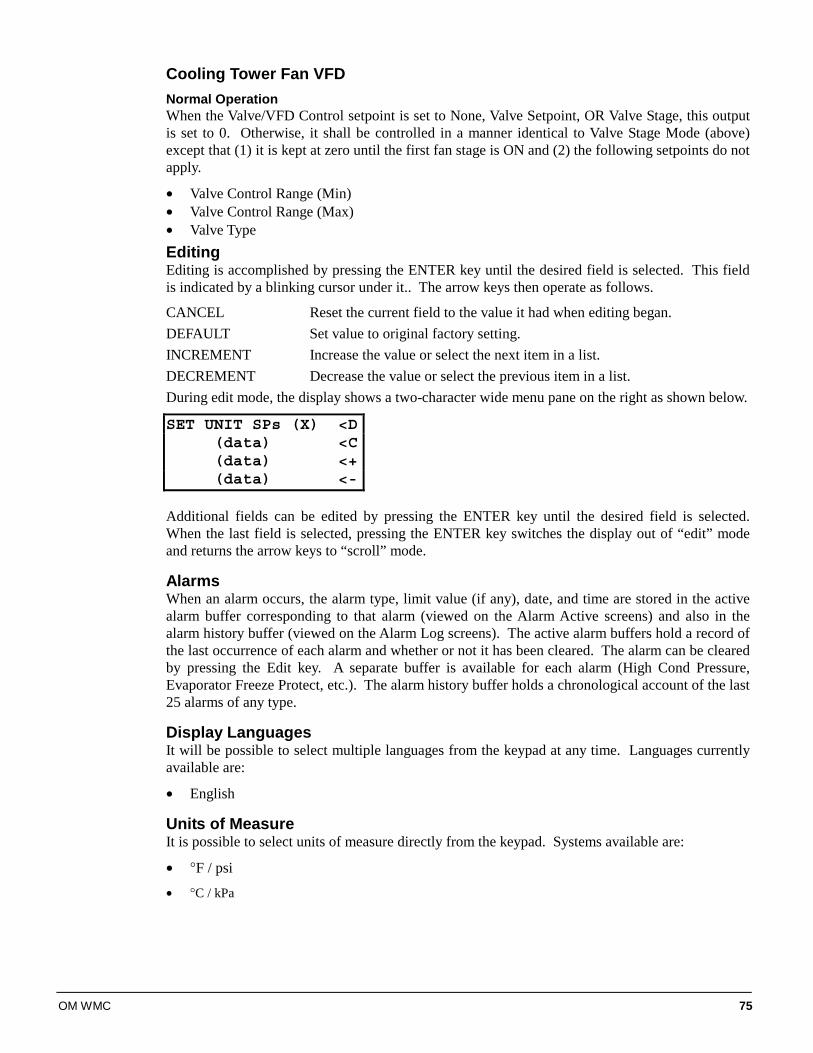
OM WMC 75
Cooling Tower Fan VFD Normal Operation When the Valve/VFD Control setpoint is set to None, Valve Setpoint, OR Valve Stage, this output is set to 0. Otherwise, it shall be controlled in a manner identical to Valve Stage Mode (above) except that (1) it is kept at zero until the first fan stage is ON and (2) the following setpoints do not apply.
• Valve Control Range (Min) • Valve Control Range (Max) • Valve Type Editing Editing is accomplished by pressing the ENTER key until the desired field is selected. This field is indicated by a blinking cursor under it.. The arrow keys then operate as follows.
CANCEL Reset the current field to the value it had when editing began. DEFAULT Set value to original factory setting. INCREMENT Increase the value or select the next item in a list. DECREMENT Decrease the value or select the previous item in a list. During edit mode, the display shows a two-character wide menu pane on the right as shown below.
SET UNIT SPs (X) <D(data) <C(data) <+(data) <-
Additional fields can be edited by pressing the ENTER key until the desired field is selected. When the last field is selected, pressing the ENTER key switches the display out of “edit” mode and returns the arrow keys to “scroll” mode.
Alarms When an alarm occurs, the alarm type, limit value (if any), date, and time are stored in the active alarm buffer corresponding to that alarm (viewed on the Alarm Active screens) and also in the alarm history buffer (viewed on the Alarm Log screens). The active alarm buffers hold a record of the last occurrence of each alarm and whether or not it has been cleared. The alarm can be cleared by pressing the Edit key. A separate buffer is available for each alarm (High Cond Pressure, Evaporator Freeze Protect, etc.). The alarm history buffer holds a chronological account of the last 25 alarms of any type.
Display Languages It will be possible to select multiple languages from the keypad at any time. Languages currently available are:
• English
Units of Measure It is possible to select units of measure directly from the keypad. Systems available are:
• °F / psi
• °C / kPa
76 OM WMC
Security Two four-digit passwords shall provide OPERATOR and MANAGER levels of access to changeable parameters. Either password can be entered using the ENTER PASSWORD screen which can be accessed in one of three ways:
1. The SET UNIT SPs menu
2. Scrolling to it (last screen in the SET UNIT SPs column)
3. By simply pressing the UP ARROW, DOWN ARROW, or DEFAULT keys while on the desired field on one of the SET screens. The password can then be entered by pressing the ENTER key, scrolling to the correct value with the UP and DOWN arrow keys, and pressing ENTER again. The length of the password shall not be indicated. Once the correct password has been entered (cases 1 and 2 above), the PASSWORD screen shall show the active password level. For case 3 above, the previously selected screen shall reappear (still in edit mode) with the cursor on the previously selected field. Once a password has been entered, it shall remain valid for 15 minutes after the last key-press. It shall be possible to change the passwords through pLAN. Parameters and screens that require the MANAGER password shall not be displayed unless the MANAGER password is active.
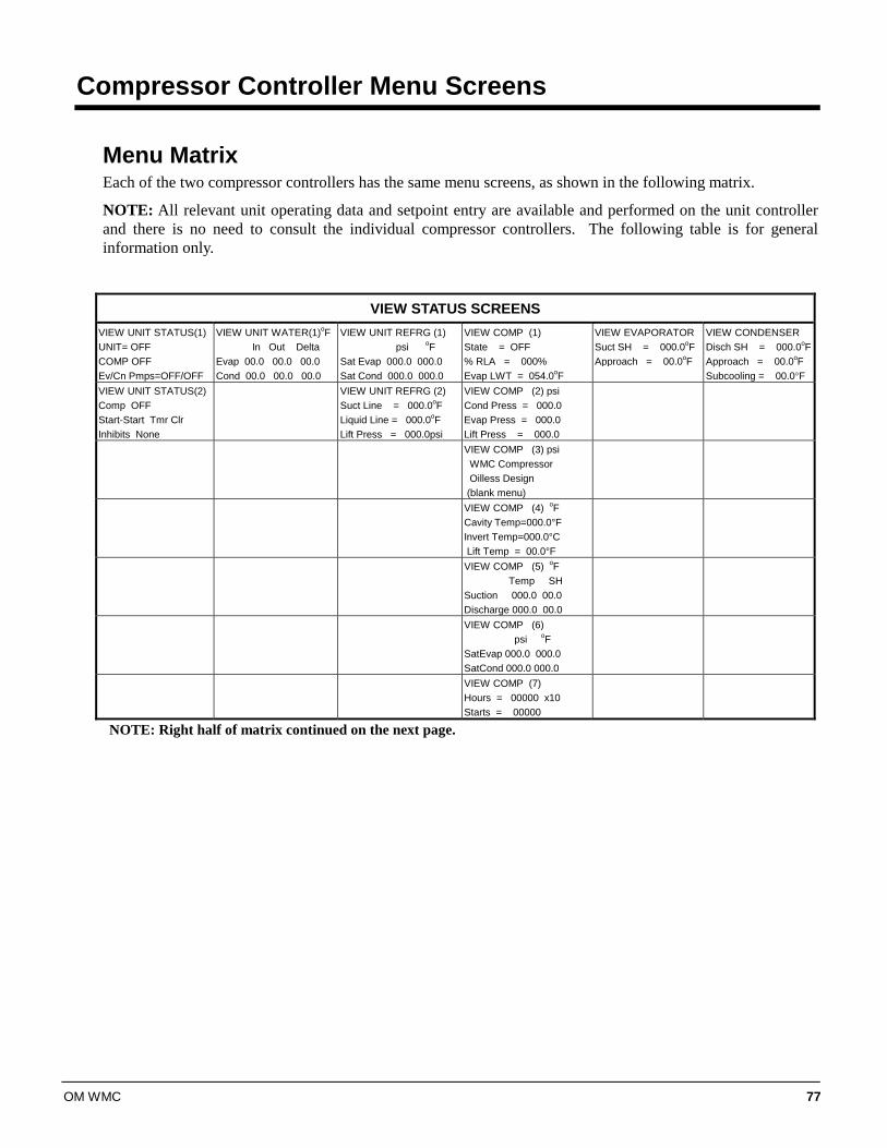
OM WMC 77
Compressor Controller Menu Screens
Menu Matrix Each of the two compressor controllers has the same menu screens, as shown in the following matrix.
NOTE: All relevant unit operating data and setpoint entry are available and performed on the unit controller and there is no need to consult the individual compressor controllers. The following table is for general information only.
VIEW STATUS SCREENS VIEW UNIT STATUS(1) UNIT= OFF COMP OFF Ev/Cn Pmps=OFF/OFF
VIEW UNIT WATER(1)oF In Out Delta Evap 00.0 00.0 00.0 Cond 00.0 00.0 00.0
VIEW UNIT REFRG (1) psi oF Sat Evap 000.0 000.0 Sat Cond 000.0 000.0
VIEW COMP (1) State = OFF % RLA = 000% Evap LWT = 054.0oF
VIEW EVAPORATOR Suct SH = 000.0oF Approach = 00.0oF
VIEW CONDENSER Disch SH = 000.0oFApproach = 00.0oF Subcooling = 00.0°F
VIEW UNIT STATUS(2) Comp OFF Start-Start Tmr Clr Inhibits None
VIEW UNIT REFRG (2) Suct Line = 000.0oF Liquid Line = 000.0oF Lift Press = 000.0psi
VIEW COMP (2) psi Cond Press = 000.0 Evap Press = 000.0 Lift Press = 000.0
VIEW COMP (3) psi WMC Compressor Oilless Design (blank menu)
VIEW COMP (4) oF Cavity Temp=000.0°F Invert Temp=000.0°C Lift Temp = 00.0°F
VIEW COMP (5) oF Temp SH Suction 000.0 00.0 Discharge 000.0 00.0
VIEW COMP (6) psi oF SatEvap 000.0 000.0 SatCond 000.0 000.0
VIEW COMP (7) Hours = 00000 x10 Starts = 00000
NOTE: Right half of matrix continued on the next page.
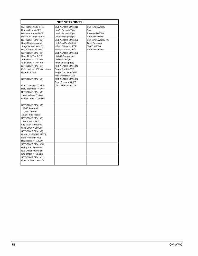
78 OM WMC
SET SETPOINTS
SET COMP#1 SPs (1) Demand Limit=OFF Minimum Amps=040% Maximum Amps=100%
SET ALARM LMTs (1) LowEvPrHold=33psi LowEvPrUnld=31psi LowEvPrStop=29psi
SET PASSWORD Enter Password:00000 No Access Given
SET COMP SPs (2) StageMode =Normal StageSequence# = 01 Max Compr ON = 01
SET ALARM LMTs (2) HighCondPr =140psi HiDschT-Load=170oF HiDschT-Stop=190oF
SET PASSWORD (2) Tech Password 00000 00000 No Access Given
SET COMP SPs (3) StageDeltaT = 1.0oF Stop-Start = 03 min Start-Start = 40 min
SET ALARM LMTs (3) WMC Compressor Oilless Design (blank mask page)
SET COMP SPs (4) Full Load = 300 sec Name Plate RLA 085
SET ALARM LMTs (4) Surge Slp Str=20oF Surge Tmp Run=06oF MtrCurThrshld=10%
SET COMP SPs (5) Nom Capacity = 0100T HotGasBypass = 30%
SET ALARM LMTs (5) Evap Freeze= 34.0°F Cond Freeze= 34.0°F
SET COMP SPs (6) InterLokTmr= 010sec UnloadTimer = 030 sec
SET COMP SPs (7) WMC Automatic Vane Control (blank mask page)
SET COMP SPs (8) MAX KW = 76.0 Lag Start = 000Sec Step Down = 060Sec
SET COMP SPs (9) Protocol =M-BUS MSTR Ident Number= 001 Baud Rate = 19200
SET COMP SPs (10) Refrg Sat Pressure Evp Offset =+00.0 psi Cnd Offset = +00.0psi
SET COMP SPs (11) ELWT Offset = +0.0 oF
OM WMC 79
BAS Interface The MicroTech II controller is available with the optional Protocol Selectability™ feature, an exclusive McQuay feature that provides easy unit interface with a building automation system (BAS). If the unit will be tied into a BAS, the controller should have been purchased with the correct factory-installed interface module. The modules can also be added in the field during or after installation. If an interface module was ordered, one of the following BAS interface installation manuals was shipped with the unit. Contact your local McQuay sales office for a replacement, if necessary. • IM 735, LONWORKS® Communication Module Installation • IM 736, BACnet® Communication Module Installation • IM 743, Modbus® Communication Module Installation
Connection to Chiller Connection to the chiller for all BAS protocols will be at the unit controller. An interface card will have to be installed in the unit controller depending on the protocol being used.

P.O. Box 2510, Staunton, Virginia 24402-2510 • (800) 432-1342 • www.mcquay.com OM WMC, 12/04
This document contains the most current product information as of this printing. For the most up-to-date product information, please go to www.mcquay.com.