Embed Size (px)
Citation preview
WAVES
WLM LOUDNESS METER
USER GUIDE

Waves WLM Loudness Meter User Guide
2
TABLE OF CONTENTS
CHAPTER 1 – INTRODUCTION ..................................................................................... 3
1.1 WELCOME ............................................................................................................... 3
1.2 PRODUCT OVERVIEW ............................................................................................... 3
1.3 CONCEPTS AND TERMINOLOGY................................................................................. 3
1.4 COMPONENTS ......................................................................................................... 5
CHAPTER 2 – USING THE WLM .................................................................................... 6
2.1 QUICK START GUIDE ................................................................................................ 6
2.2 USAGE NOTES ......................................................................................................... 7
CHAPTER 3 – INTERFACE AND CONTROLS ............................................................. 11
3.1 INTERFACE ............................................................................................................ 11
3.2 CONTROLS AND DISPLAYS ...................................................................................... 13
CHAPTER 4 – THE WAVESYSTEM ............................................................................. 20
4.1 THE WAVESYSTEM TOOLBAR ................................................................................. 20
4.2 PRESET HANDLING ................................................................................................ 20
4.3 INTERFACE CONTROLS ........................................................................................... 23
4.4 WAVES PREFERENCES (PRO TOOLS ONLY) ............................................................. 25
APPENDIX .................................................................................................................... 26
Waves WLM Loudness Meter User Guide
3
Chapter 1 – Introduction
1.1 Welcome
Thank you for choosing Waves! In order to get the most out of your Waves processor,
please take the time to read through this manual.
May we also suggest that you become familiar with www.wavesupport.net. There you
will find an extensive Answer Base, the latest Tech Specs, detailed Installation
guides, new Software Updates, and current information on Authorization and
Registration.
By signing up at www.wavesupport.net, you will receive personalized information on
your registered products, reminders when updates are available, and information on
your authorization status.
1.2 Product Overview
The Waves WLM Loudness Meter plugin provides precision loudness measurement and
metering for broadcast, movie trailers, games, packaged media and more. Fully
compliant with all current ITU, EBU and ATSC specifications, the WLM offers
comprehensive Momentary, Short Term, Long Term, Loudness Range, and True Peak
readouts, plus a unique warning and logging system that keeps track of your levels, and
lets you know when you’ve exceeded them—or fallen short. The WLM Plus expands
upon these powerful metering capabilities with the addition of an ITU compliant True
Peak Limiter including Gain and Trim controls to easily normalize your program
loudness. Ideal for content creators, post production houses and cable head-end
facilities, the WLM is an affordable, all-in-one loudness metering software solution.
1.3 Concepts and Terminology
Loudness Metering
Loudness metering measures signal loudness using special weight filtering and
averaging techniques which allow perceived loudness levels to be expressed
numerically, using a variety of measurement scales:

Waves WLM Loudness Meter User Guide
4
• LU = Loudness Units
• LUFS = Loudness Units relative to Full Scale
• LKFS = Loudness, K-weighted, relative to Full Scale
• dBFS = Decibels relative to Full Scale
• dBTP = Decibels True Peak
Measurement Standards
WLM is fully compliant with all contemporary loudness measurement standards:
• ITU-R BS.1770-3
• EBU R 128
• ATSC A/85
Measurement Methods
WLM allows the user to choose one of three measurement methods:
• EBU uses foreground audio as the loudness anchor.
• LM1 measures and averages loudness across the whole program.
• DIAL uses dialog as the loudness anchor, measuring and averaging loudness only
when dialog is detected.
Timescales
WLM provides readouts for four timescales:
• Momentary
• Short Term
• Long Term
• True Peak

Waves WLM Loudness Meter User Guide
5
Weighting
WLM provides readouts for the following weighting types:
• ITU-R B.S.1770 – K-Weighting
• Leq(a)
• Leq(b)
• Leq(c)
• Leq(m)
For in-depth information about measurement methods, measurement standards,
timescales, and weighting, please see the Appendix at the end of this manual.
1.4 Components
The WLM has eight components:
WLM Mono
WLM Stereo
WLM Multichannel 5.0
WLM Multichannel 5.1
WLM Plus Mono
WLM Plus Stereo
WLM Plus Multichannel 5.0
WLM Plus Multichannel 5.1
In all components, measurements are summed into a single number. To view
measurements for a single channel or combination of channels, use the Channels
control.
Waves WLM Loudness Meter User Guide
6
Chapter 2 – Using the WLM
2.1 Quick Start Guide
The WLM’s default preset is designed to check levels as per both EBU and ATSC specs.
As both specifications allow some tolerance, the target is set to -24 dB, 1 dB lower than
the EBU standard; however, -1 dB is not considered a violation.
1. Identify your loudness requirements.
2. Insert WLM or WLM Plus on your program output.
3. Select the appropriate preset.
4. If you would like to create a log file, click the Export CSV button.
5. Play your program through WLM.
6. Watch the meters to view the loudness measurements.
After playing the entire program, check the Long Term meter to ascertain that your
program complies with the required target.
To normalize the loudness measurement and ensure the program material does not
exceed True Peak levels, you may use the WLM Plus component in the following
manner after the initial measurement described above:
1. Click the Trim button.
2. Click Reset button.
3. Activate the True Peak Limiter.
4. If you would like to create a log file, click the Export CSV button.
5. Play your program through WLM Plus to re-measure.

Waves WLM Loudness Meter User Guide
7
2.2 Usage Notes
The following are a few of the WLM features designed to enhance your workflow.
Presets
WLM presets fulfill most of the requirements commonly encountered by post production
engineers and content providers.
The WLM factory default is designed to cover most cases, and its results will
meet both EBU and ATSC recommendations for most programs.
The “EBU R 128 18 dB” preset complies with the recommendations specified in
the EBU R 128 and its accompanying technical papers including tech 3341 –
3343 and ITU-R B.S. 1770-2
The “ATSC A85” preset features follows recommendations specified by the
Advanced Television Systems Committee.
Set As Default Preset
To save a particular setup as the WLM default, click Save and choose Set As Default
Preset. (You can still load factory presets or saved presets.)
Waves WLM Loudness Meter User Guide
8
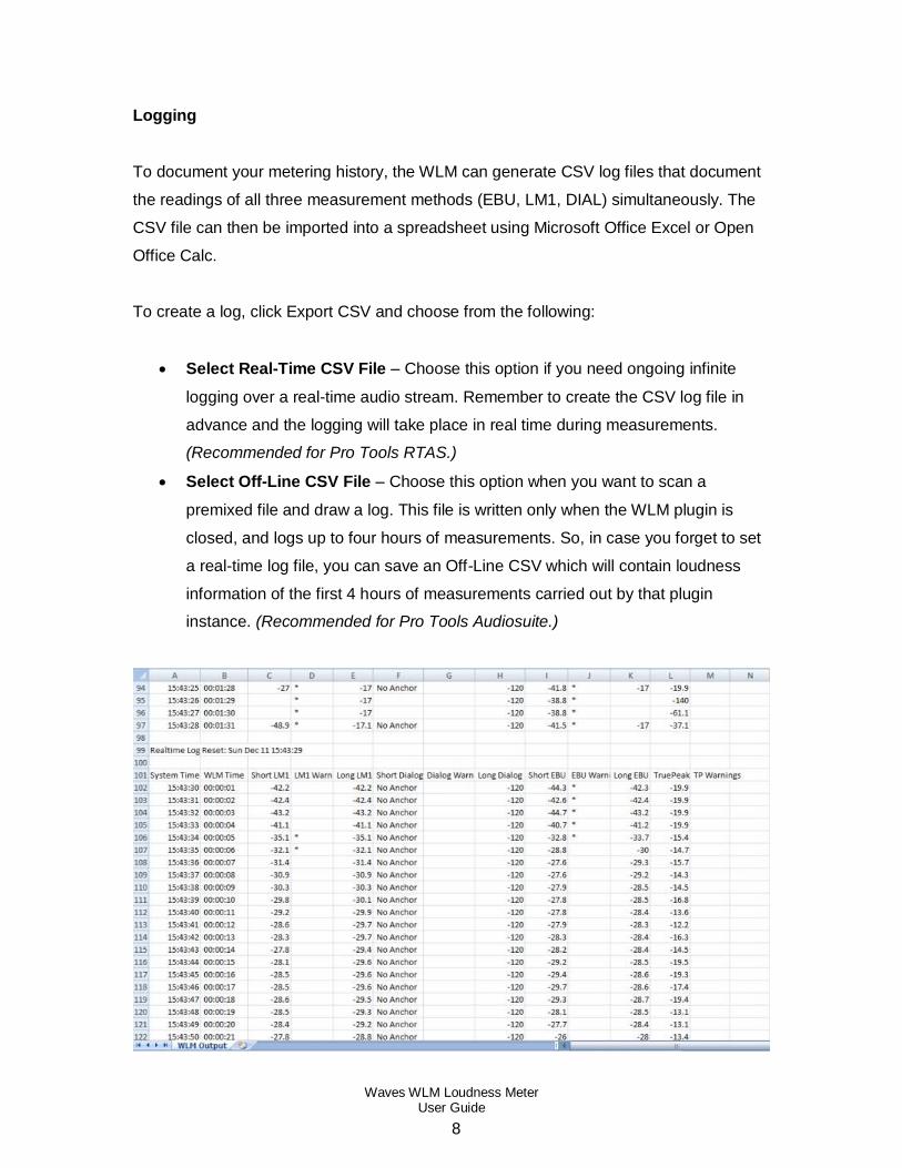
Logging
To document your metering history, the WLM can generate CSV log files that document
the readings of all three measurement methods (EBU, LM1, DIAL) simultaneously. The
CSV file can then be imported into a spreadsheet using Microsoft Office Excel or Open
Office Calc.
To create a log, click Export CSV and choose from the following:
Select Real-Time CSV File – Choose this option if you need ongoing infinite
logging over a real-time audio stream. Remember to create the CSV log file in
advance and the logging will take place in real time during measurements.
(Recommended for Pro Tools RTAS.)
Select Off-Line CSV File – Choose this option when you want to scan a
premixed file and draw a log. This file is written only when the WLM plugin is
closed, and logs up to four hours of measurements. So, in case you forget to set
a real-time log file, you can save an Off-Line CSV which will contain loudness
information of the first 4 hours of measurements carried out by that plugin
instance. (Recommended for Pro Tools Audiosuite.)

Waves WLM Loudness Meter User Guide
9
Warnings
The WLM issues warnings when loudness targets are not met or exceeded.
Short Term Min – When short term loudness falls below the minimum value, the display
appears in light blue until loudness is back above the minimum for 5 seconds. This
warning is also registered by the Unders counter and in the CSV log file.
Short Term Max – When short term loudness exceeds the maximum value, the display
appears in red until loudness falls back below the maximum for 5 seconds. This warning
is also registered by the Overs counter and in the CSV log file.
True Peak Max – When True Peak loudness exceeds the maximum value, the display
appears in red until the peak hold numeric display is reset.
Whenever a warning is issued, an asterisk (*) will appear in the corresponding warning
column of the CSV log.
Automation Warning
The WLM registers Overs and Unders in the counters below the Short Term numeric
display. If you would like to know when these readings occurred, you can either refer to
your log, or use the Automation Warning feature.
The WLM includes a special control that does not appear on the plugin interface, but
does show up in the automation parameters. When the host is set to write automation for
the Automation Warnings control, it will display a line in the middle of the lane indicating
compliant loudness levels. When an Over is detected, it will write a step to the maximum
value; conversely, it will display a downward step when an Under is detected:

Waves WLM Loudness Meter User Guide
10
You can use this automation lane to identify parts of the program that require further
attention. Adjust the loudness immediately preceding and during the event; once you
have fixed the problem area, ascertain the warning does not re-occur by resetting the
WLM and measuring the section again, starting a bit before the Over appears.

Waves WLM Loudness Meter User Guide
11
Chapter 3 – Interface and Controls
3.1 Interface
WLM

Waves WLM Loudness Meter User Guide
12
WLM Plus

Waves WLM Loudness Meter User Guide
13
3.2 Controls and Displays
Meters Section
1. Short Term Displays (in LUFS/LKFS) perceived short term loudness.
2. Long Term Displays (in LUFS) perceived loudness averaged across the program
signal that passes through the plugin during the period specified by the Integration Time
Counter.
3. Range Displays (in LU) the overall loudness range across the program signal that
passes through the plugin.
4. Momentary Displays (in LUFS) momentary loudness levels, according to the
Momentary scale control settings. A peak value indicator displaying maximum
momentary loudness is located to the right of the bar meter, and can be reset by clicking
on it.
Range: -53 to -8

Waves WLM Loudness Meter User Guide
14
5. True Peak Displays (in dBTP) inter-sample peaks which do not register in the sample
data but may occur during reproduction of the digital signal. A peak value indicator
displaying maximum True Peak is located to the right of the bar meter, and can be reset
by clicking on it.
Range: -58 to +6
6. Unders Displays the number of times the signal goes below the specified Short Term
Min value indicated in the settings panel.
7. Overs Displays the number of times the signal exceeds the specified Short Term Max
value indicated in the settings panel.
8. Measurements Play/Pause Determines if program loudness is registered in the WLM
memory for averaging long term loudness range. When Play is activated, loudness is
registered and averaged.
9. Follow Transport Determines if measurement starts and stops according to host
application transport controls. When engaged, the timer also starts and stops according
to host application transport controls.
10. Timer Indicates the amount of time measurements have been taken and integrated.
11. Reset Resets the Long Term, Range, Overs and Unders counters and returns the
integration timer to 00:00:00.

Waves WLM Loudness Meter User Guide
15
Processing Panel The Processing Panel is available in the WLM Plus components
12. True Peak Limiter Activates the True Peak Limiter compliant with ITU 1770-3. The
threshold is automatically defined by the “True Peak Max” value located in the “Settings
Panel”. The True Peak Limiter is independent of the “Channels” setting and affects all
channels. The limiter does not introduce make-up gain.
Range: On /Off
Default: Off
13. GR Meter Displays the amount of gain attenuation being applied by the Limiter. A
peak value indicator displaying maximum gain reduction is located to the right of the bar
meter, and can be reset by clicking on it.
14. Gain Fader / Slider control allowing to boost or cut (Linear Gain) the meter’s input by
18 dB. This affects the signal before all measurements available in the plug-in. The Gain
is independent of the “Channels” setting and affects all channels.
Range: +/-18 dB
Default: 0 dB
15. Trim A clickable button combined with a value indicator. The value indicator displays
in real time the difference between the Target Level and Long Term Loudness
measurement (higher resolution figure). Clicking the “Trim” will apply the calculated
value to the Gain Fader. It is recommended to use this feature once completing a
measurement and not during playback. The Trim can boost the Gain by a maximum of
12 dB and cut the gain by it’s maximum available range. Once “Trim” has been applied
the control is unavailable until a new long term measurement has been calculated.
Default: 0 dB
Waves WLM Loudness Meter User Guide
16
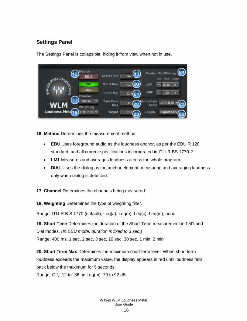
Settings Panel
The Settings Panel is collapsible, hiding it from view when not in use.
16. Method Determines the measurement method.
EBU Uses foreground audio as the loudness anchor, as per the EBU R 128
standard, and all current specifications incorporated in ITU-R BS.1770-2.
LM1 Measures and averages loudness across the whole program.
DIAL Uses the dialog as the anchor element, measuring and averaging loudness
only when dialog is detected.
17. Channel Determines the channels being measured.
18. Weighting Determines the type of weighting filter.
Range: ITU-R B.S.1770 (default), Leq(a), Leq(b), Leq(c), Leq(m), none
19. Short Time Determines the duration of the Short Term measurement in LM1 and
Dial modes. (In EBU mode, duration is fixed to 3 sec.)
Range: 400 ms, 1 sec, 2 sec, 3 sec, 10 sec, 30 sec, 1 min, 2 min
20. Short Term Max Determines the maximum short term level. When short term
loudness exceeds the maximum value, the display appears in red until loudness falls
back below the maximum for 5 seconds.
Range: Off, -12 to -36; in Leq(m) 70 to 92 dB
Waves WLM Loudness Meter User Guide
17
21. Short Term Min Determines the minimum short term level. When short term
loudness falls below the minimum value, the display appears in light blue until loudness
is back above the minimum for 5 seconds.
Range: -12 to -90, Off; In Leq(m), 42 to 83 dB
Please note: When Leq(m) is selected, Short Term Max and Min controls scale to dBSPL
positive values.
22. True Peak Max Determines the maximum true peak level. When True Peak
loudness exceeds the maximum value, the display appears in red until the peak hold
numeric display is reset. This control also defines the True Peak Limiter’s threshold in
the WLM Plus components.
Range: 0 to -25 dBTP
23. Target Determines the target level.
Range: Off, -33 to -9 dB
24. Custom Pre Filtering Provides low pass (LPF) and high pass (HPF) filters that pre-
filter the audio prior to loudness measurement, useful when checking content intended
for playback on devices with limited frequency ranges, such as handheld gaming
consoles.
LPF On
Range: On, Off
Default: Off
LPF Frequency
Range: 2000 Hz to 18000 Hz
Default: 10000 Hz
Waves WLM Loudness Meter User Guide
18
LPF Slope
Range: 12 dB/Oct, 6 dB/Oct
Default: 12 dB/Oct
HPF On
Range: On, Off
Default: Off
HPF Frequency
Range: 20 Hz to 2000 Hz
Default: 120 Hz
HPF Slope
Range: 12 dB/Oct, 6 dB/Oct
Default: 12 dB/Oct
25. Momentary Scale Determines the scale displayed in the momentary bar meter.
LKFS: -6 to -54
LU 18 dB: 17 to -31
LUFS 18 dB: -6 to -54
LU 9 dB: 9 to -18
LUFS 9 dB: -14 to -41

Waves WLM Loudness Meter User Guide
19
26. Logging Displays CSV logging file options.
Select Real-Time CSV File – Choose this option if you need ongoing infinite
logging over a real-time audio stream. Remember to create the CSV log file in
advance and the logging will take place in real time during measurements. (Pro
Tools RTAS should choose this method.)
Select Off-Line CSV File – Choose this option when you want to scan a
premixed file and draw a log. This file is written only when the WLM plugin is
closed, and logs up to four hours of measurements. So, in case you forget to set
a real-time log file, you can save an Off-Line CSV which will contain loudness
information of the first 4 hours of measurements carried out by that plugin
instance. (Pro Tools Audiosuite users should choose this method.)
Please note: You must create your log file prior to measuring your program. Off-line
logs are generated only upon termination of the plugin instance.

Waves WLM Loudness Meter User Guide
20
Chapter 4 – The WaveSystem
4.1 The WaveSystem Toolbar
All Waves plugins feature the WaveSystem toolbar which takes care of most
administrative functions you will encounter while working with your Waves software. The
features of the WaveSystem toolbar are the same on practically all Waves plugins, so
familiarity with its features will be helpful whichever plugin you are using.
Toolbar Functions
Opens the plugin About box
Undo Undoes the last 32 actions
Redo Redoes the last 32 undone actions
L/R Arrows Move to the previous or next preset
Load Recalls presets from file
Save Saves presets in the Waves file formats
? Opens the PDF manual for the plugin you are using
4.2 Preset Handling
Preset Types
Factory Presets are permanent presets in the Load menu. Factory presets cannot be
overwritten or deleted. When applicable, different component plugins may have different
factory presets.
User Presets are your favorite settings of the plugin saved as a preset in the Load
menu, under ‘User Presets’. User Presets can be overwritten and deleted.
Setup Files may contain more than one preset. For example, a single file can contain all
the presets for a session. When you open a Setup File, all its setups become part of
your Load pop-up menu for fast access. This can be particularly useful with multiple

Waves WLM Loudness Meter User Guide
21
instances of a plugin in a single session. By saving all the settings you create into a
single Setup File, they can all be quickly available for every instance of that plugin.
Loading Presets and Setups
Click on the Load button to see the Load pop-up menu. The menu is divided into four
sections. If a section is not currently available it will not appear in the Load pop-up menu.
Open Preset File… Select to open any setup or preset file, whether from the Library or
your own creations.
‘Filename.xps’: Displays any currently loaded Setup File and its presets.
Factory Presets: Displays the default Factory Presets.
User Presets: Displays any loaded User Presets.
Saving Presets and Setups
Click on the Save button to see the Save pop-up menu. Four options are available. If an
option is not currently available it will be grayed out and inaccessible.
Save to New File… Select this to start a new Setup file. There are two
prompts - first for the setup filename, then for the
preset name. You must provide a name for both the
setup file and the preset. Click OK (ENTER) to
complete the save. It is a good idea to create a
folder in which to save several setup files for a
project.
Save ‘File Name’ – “Preset Name” Overwrites the settings of the loaded preset
(whether a User Preset or a preset from a Setup
File) with the current settings. If a Setup File is
currently loaded, the name of the Setup File is
displayed followed by the name of the preset itself.
If a User Preset is loaded, its name is displayed.
Waves WLM Loudness Meter User Guide
22
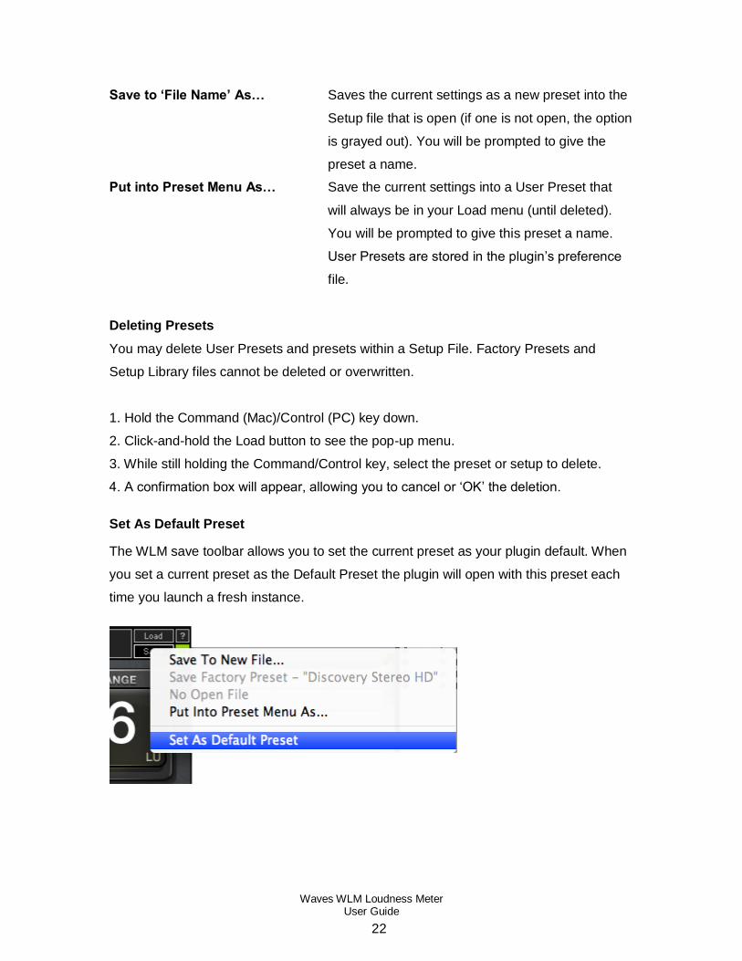
Save to ‘File Name’ As… Saves the current settings as a new preset into the
Setup file that is open (if one is not open, the option
is grayed out). You will be prompted to give the
preset a name.
Put into Preset Menu As… Save the current settings into a User Preset that
will always be in your Load menu (until deleted).
You will be prompted to give this preset a name.
User Presets are stored in the plugin’s preference
file.
Deleting Presets
You may delete User Presets and presets within a Setup File. Factory Presets and
Setup Library files cannot be deleted or overwritten.
1. Hold the Command (Mac)/Control (PC) key down.
2. Click-and-hold the Load button to see the pop-up menu.
3. While still holding the Command/Control key, select the preset or setup to delete.
4. A confirmation box will appear, allowing you to cancel or ‘OK’ the deletion.
Set As Default Preset
The WLM save toolbar allows you to set the current preset as your plugin default. When
you set a current preset as the Default Preset the plugin will open with this preset each
time you launch a fresh instance.

Waves WLM Loudness Meter User Guide
23
4.3 Interface Controls
Controls can be in one of three states:
1. Not Selected where the control is not the target of any user entry
2. Selected where the control is the target of mouse control entry only
3. Selected and Active where the control is the target for both mouse and
keyboard entry
Toggle Buttons
Toggle buttons display the state of a control, and allow switching between two or more
states. Single-click to change the control’s state. Some toggle buttons have a text
display which updates with the current setting, and others (bypass, solo, or monitoring
toggles) illuminate when the control is active.
Some plugins have link buttons between a pair of toggle buttons, allowing click-and-
drag adjustment while retaining the offset between the controls.
Value Window Buttons
Value windows display the value of a control and allow click-and-drag adjustment, or
direct control via the keyboard.
Using the mouse, click-and-drag on the value window to adjust. Some value
windows support left/right, some up/down (as you hover over a button, arrows
will appear to let you know which direction of movement that button supports).
You may also use your mouse-wheel to adjust parameter values.
Using the arrow keys, click once with mouse to select the button, and then use
up/down – left/right (depending on the direction supported by that button) to
move in the smallest incremental steps across the button’s range (holding down
the arrow keys will move faster through the range).
Using key entry, double click on the button to open the value window, and
directly enter the value from your keyboard. If you enter an out of range number,
the button stays selected but remains at the current setting. (System beeps if
system sounds are on.)

Waves WLM Loudness Meter User Guide
24
Some plugins have link buttons between a pair of value windows, allowing click-and-
drag adjustment while retaining the offset between the controls.
Sliders
Click or scroll the mouse-wheel on the slider itself or anywhere within the sliders track.
The numerical value of the slider settings is displayed in a hover window above the
slider path.
Hover Box
Hovering boxes will appear and display the control value when hovering with the mouse
over the control.
Multiple Control Selection
One of the most powerful features of the WaveSystem is the ability to select and adjust
multiple controls simultaneously. Using the mouse, drag-select the desired group of
buttons or graphic controls by clicking and holding at a point outside the controls, and
forming a rectangle that includes the controls you wish to adjust. Alternatively, press and
hold Shift while clicking the mouse on any control you wish to link. This method is useful
when you want to select two or more controls that are not adjacent to one another.
TAB Functions
TAB moves the ‘selected’ status to the next control, with shift-TAB moving in the reverse
direction. Additionally, the Mac has an option-TAB function for ‘down’ movement and
shift-option-TAB for ‘up’ movement where applicable. If you have several Value Window
Buttons selected, TAB functions will take you through the selected controls only.
Hitting Esc or Return will return the 'focus' to the DAW application.

Waves WLM Loudness Meter User Guide
25
4.4 Waves Preferences (Pro Tools only)
When launching Pro Tools, hold Shift to view the Waves plugin Preferences window.
The following options are available:
Don't use AudioSuite plugins
Don’t use RTAS plugins
Rescan all plugins
HUI control surface support (low resolution)
Enable single-click text entry
Waves WLM Loudness Meter User Guide
26
Appendix
Audio Loudness Metering
Loudness is the perception of audio level as perceived by humans. In broadcast, it is
especially important that transmitted audio levels are consistent; otherwise, listeners
would need to adjust the volume for every song, movie scene, commercial
advertisement, and so on.
Loudness metering measures signal loudness using special weight filtering and
averaging techniques which allow perceived loudness levels to be expressed
numerically.
These numbers can be used by broadcasters to identify the loudness of a particular
program or advertisement to determine if it is consistent with station or network
regulations. Many countries enact laws legislating permissible loudness levels, and
empower broadcast authorities to monitor levels and impose fines on broadcasters who
violate these guidelines.
Broadcast networks typically provide loudness specifications to their contractors,
post production and mixing facilities. These specifications indicate acceptable loudness
target values, as well as which weighting filters and timescale need to be taken into
consideration. In many cases, they will even recommend a specific device that
measures program loudness according to their specifications.
Loudness Theory and Practice
The WLM was created to comply with contemporary loudness measurement standards,
as described in a number of technical papers as listed herein:
ITU-R BS.1770-3 (August 2012) - Algorithms to measure audio programme loudness
and true-peak audio level.
http://www.itu.int/dms_pubrec/itu-r/rec/bs/R-REC-BS.1770-3-201208-I!!PDF-E.pdf
Waves WLM Loudness Meter User Guide
27
This recommendation by the International Telecommunication Union is a staple in
contemporary loudness measurements. It is a second generation revision, after the
original specification created widely-accepted measurement guidelines which utilized a
special weighting curve (K weighting) and established the LKFS measurement unit:
Loudness K-Weighted relative to Full Scale.
EBU R 128 (August 2011rev.) - Loudness normalisation and permitted maximum level of
audio signals.
http://tech.ebu.ch/docs/r/r128.pdf
This recommendation by the European Broadcasting Union is gaining wide acceptance
as standard loudness practice across Europe. The EBU R 128 is a guideline paper
which considers the ITU recommendations and expands upon them, referencing to
specifications described in another 4 technical papers:
EBU Tech 3341 Metering Specification
EBU Tech 3342 Loudness Range Descriptor
EBU Tech 3343 Practical Guidelines
EBU Tech 3344 Distribution Guidelines
The EBU spec takes into account that voice and dialog loudness can miss certain loud
passages, and uses the “Foreground” sound as the basis for loudness, Using a special
gating scheme with an absolute and a relative gate to identify background sound and not
include it in the averaged long term loudness.
ATSC A/85 (July 2011) - Techniques for Establishing and Maintaining Audio Loudness
for Digital Television.
http://www.atsc.org/cms/standards/a_85-2011a.pdf
This recommendation paper from the Advanced Television Systems Committee is
gaining wide acceptance from US broadcast networks, especially with regard to digital
TV. This latest revision approaches the EBU recommendations, but maintains that
Dialog be used as the anchor for loudness measurements. While using a dialog anchor
has proven highly accurate for talk and narration-based programs, for action and musical
programs, measuring all audio provides better results.

Waves WLM Loudness Meter User Guide
28
Measurement Method
WLM allows the user to choose from three measurement methods:
EBU – As per the EBU recommendation, WLM displays three different
timescales: Momentary, Short and Long/Integrated, as well as True Peak and
Loudness Range, which are also part of the EBU recommendation. The
Momentary scale can show 2 resolutions, 18 dB and 9 dB in either LUFS or LU.
With EBU selected as the measurement method, WLM uses foreground audio as
the loudness anchor and, while it will measure short term loudness across the
whole program, it will average and integrate only the foreground loudness to the
long term measurement, gating out sections that fall more than 8 dB below the
normal foreground audio. (The exact specification may be found online.)
The WLM was tested using qualification material supplied by PLoud and EBU. To
be fully compliant with the EBU recommendation, the weighting has to be per
ITU-R BS 1770 and the target loudness is always -23 LUFS = 0 LU. Factory
presets marked “EBU” ensure that its settings are fully EBU-compliant.
LM1 – This method sometimes called “All” measures and averages loudness
across the whole program, without selecting any single element as an anchor.
DIAL – This method uses dialog as the loudness anchor, measuring and
averaging loudness only when dialog is detected. It uses the same specifications
as the LM1 but uses the Dialog as the anchor element, effectively measuring and
averaging loudness only when dialog is detected, gating out any sections that do
not include dialog.
Weighting and Timescales
One of the basic concepts of loudness measurement theory is weighting. Essentially
human hearing is profiled with a curve that describes our sensitivity to frequencies. The
general rule is that all frequencies generated at the same energy will seem louder in the
mid-range frequencies, and lower in very high and very low frequencies. This rule has

Waves WLM Loudness Meter User Guide
29
different specific results at different general SPL levels. i.e., the lower the overall energy,
the bigger these differences will become, and at low levels, the ear will focus on mid and
high mid frequencies and completely lose perception of the ultra high and very low
frequencies.
The basis of this theory is well known as the Fletcher Munson equal loudness curves,
which describe frequency response “Filters” that enable humans to perceive equal
loudness across the audible frequency range. Additionally, the “opposites” of these
filters were used to filter audio content and weigh its relative loudness to the human ear.
Most common among these “weighting filters” is the A weighting, used in Leq(a) based
loudness measurements for acoustic measurements. The refinement of weighting lead
to the success of K-Weighting, which is the contemporary loudness curve recommended
in the ITU-R B.S.1770 as well as the EBU and ATSC specifications.
Another critically important concept in loudness metering is the timescale of the
measurement. Psychoacoustic theory stresses that we perceive loudness from the
average, rather than the momentary peaks, i.e., a very short and loud transient peak
won’t make as big an impression on our perception of loudness, but a similar event
lasting around half a second can cause discomfort. The same amount of energy lasting
for several seconds or more will have an impact on our longer term perception of
loudness we hear. Several timescales that affect our perception of loudness have been
established and documented in the ITU and EBU recommendations:
Momentary measures 400 ms of signal, sufficient for the shortest loudness
timescale. As this measurement is quite fast, WLM displays it using a bar meter
with smoothed release ballistics.
Short Term or Short averages loudness over a period of 1 to several seconds,
with some overlap between the time slices. WLM shows this number in a large
numeric display; dB is rounded to the nearest whole number; the same short
term value with 1 decimal space is visible within the same window in a smaller
font.

Waves WLM Loudness Meter User Guide
30
Long Term or Integrated relates to ongoing averaging of the whole program.
This is very often the basic value that interests loudness users. Over time, the
program averages to the required target.
True Peak provides sub-sample accuracy for measuring inter-sample peaks in
digital audio. Depending on the current wave front, two consecutive samples may
interpolate to a higher one that is missed in quantization.


![Sitecom WLM-4501 Full Manual English]](https://img.pdfslide.us/doc/110x75/53ff0b81dab5caed078b4695/sitecom-wlm-4501-full-manual-english.jpg)