Embed Size (px)
Citation preview
Inductive Hardening
W.Lindert
Know-How in Motion™ 2
Introduction / The Company
Sauer-Danfoss is a worldwide leader in the design, manufacture and sale of engineered hydraulic, electric and electronic systems and components, for use primarily in applications of mobile equipment.
– One of the largest manufacturers and suppliers of mobile hydraulics, electro-hydraulics and full-electric solutions in the world.
– 10,000 employees.
– Revenue approximately $2 billion USD.
– 26 manufacturing/engineering sites (include joint-ventures) in the Americas, Europe and the Asia-Pacific regions.
– Executive Offices in Lincolnshire near Chicago, USA.
Know-How in Motion™ 3
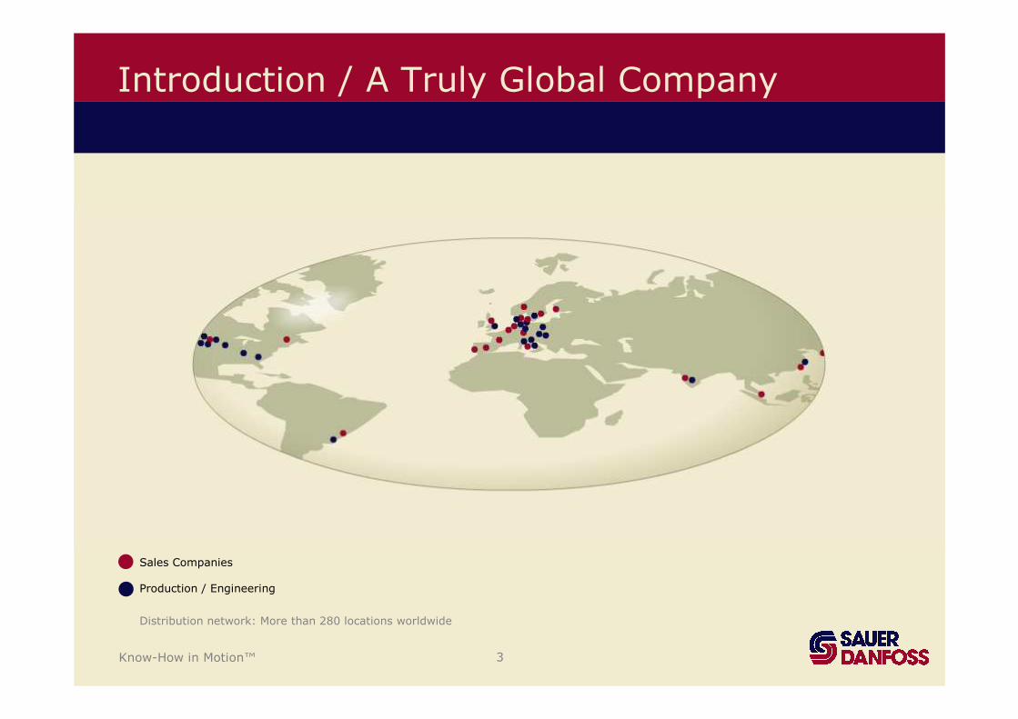
Introduction / A Truly Global Company
Sales Companies
Production / Engineering
Distribution network: More than 280 locations worldwide
Know-How in Motion™ 4
© Blue Graphics Concept Sauer-Danfoss
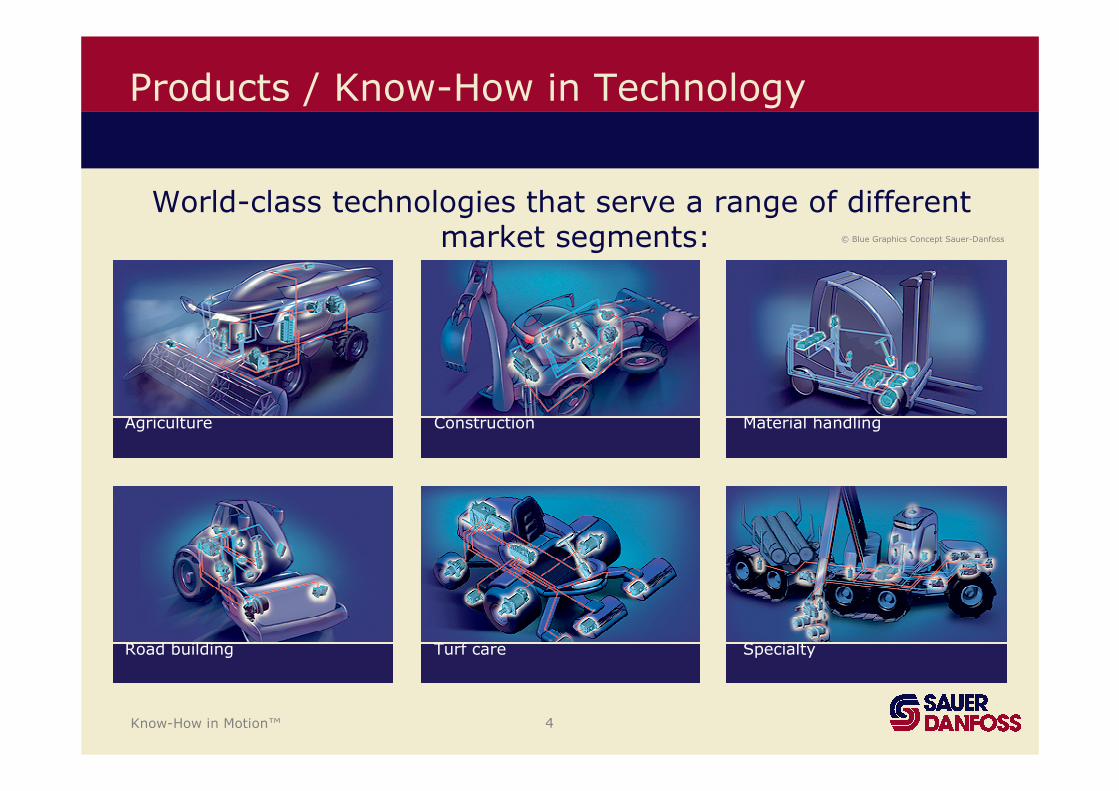
Products / Know-How in Technology
World-class technologies that serve a range of different market segments:
Agriculture Construction Material handling
Road building Turf care Specialty
Know-How in Motion™ 5
Induction Hardening
• The principle of inductive hardening
Summary
• Material for inductive hardening, and which hardness isreachable.
• Practice and design requirement
• Quality assurance
• Conclusion

Know-How in Motion™ 6
The Principle of Inductive Hardening
AC3
AC1
Austeniteinhomogeneous
homogeneous
Log t
Tem
pera
ture t
ZTA/TTH
Log t
Tem
pera
ture
A
MS
FP
B
AC3
t
AC2
ZTU/TTT
SHD
Heat conduction
Heat source
As the heat source / inductor moves over thesurface of a workpart, heat is generated in the working part.
A high speed of heating is realised(ZTA/TTH).
A martensitic transformation happens in the border zone due to high cooling rates (by external cooling effects and self cooling).
The border zone will get a high hardness
Know-How in Motion™ 7
The Principle of Inductive Hardening
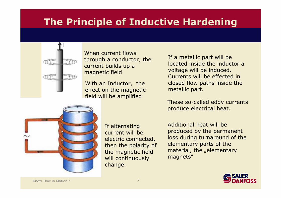
When current flowsthrough a conductor, thecurrent builds up a magnetic field
With an Inductor, theeffect on the magneticfield will be amplified
If alternatingcurrent will beelectric connected, then the polarity of the magnetic fieldwill continuouslychange.
If a metallic part will belocated inside the inductor a voltage will be induced. Currents will be effected in closed flow paths inside themetallic part.
These so-called eddy currentsproduce electrical heat.
Additional heat will beproduced by the permanent loss during turnaround of theelementary parts of thematerial, the „elementarymagnets“
Know-How in Motion™ 8
1e
δ X
i0
i
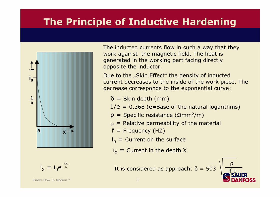
The inducted currents flow in such a way that theywork against the magnetic field. The heat isgenerated in the working part facing directlyopposite the inductor.
Due to the „Skin Effect“ the density of inductedcurrent decreases to the inside of the work piece. Thedecrease corresponds to the exponential curve:
δ = Skin depth (mm)
1/e = 0,368 (e=Base of the natural logarithms)
ρ = Specific resistance (Ωmm2/m)
µ = Relative permeability of the material
f = Frequency (HZ)
It is considered as approach: δ = 503ρ
f µ
i0 = Current on the surface
iX = Current in the depth X
iX = i0e-X
δ
The Principle of Inductive Hardening
Know-How in Motion™ 9
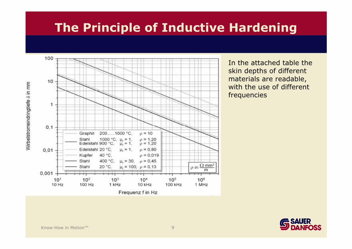
In the attached table theskin depths of different materials are readable, with the use of different frequencies
The Principle of Inductive Hardening
Know-How in Motion™ 10
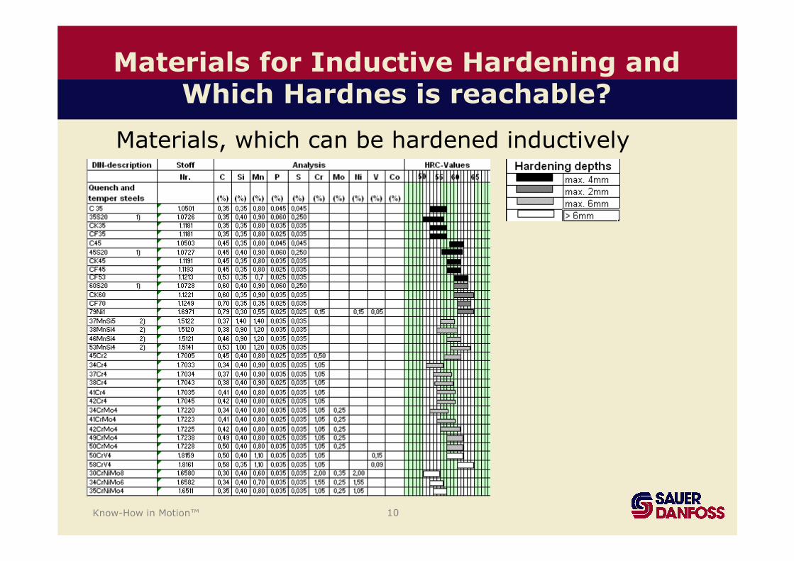
Materials for Inductive Hardening and Which Hardnes is reachable?
Materials, which can be hardened inductively
Know-How in Motion™ 11
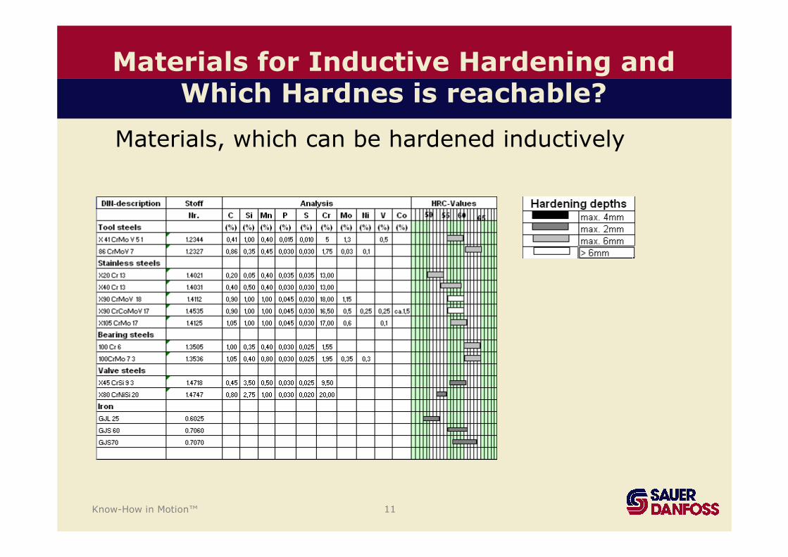
Materials, which can be hardened inductively
Materials for Inductive Hardening and Which Hardnes is reachable?
Know-How in Motion™ 12
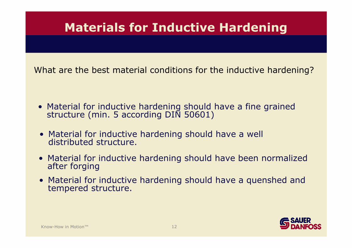
• Material for inductive hardening should have a fine grainedstructure (min. 5 according DIN 50601)
Materials for Inductive Hardening
• Material for inductive hardening should have a well distributed structure.
• Material for inductive hardening should have been normalizedafter forging
• Material for inductive hardening should have a quenshed and tempered structure.
What are the best material conditions for the inductive hardening?
Know-How in Motion™ 13
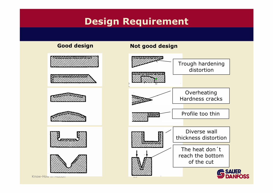
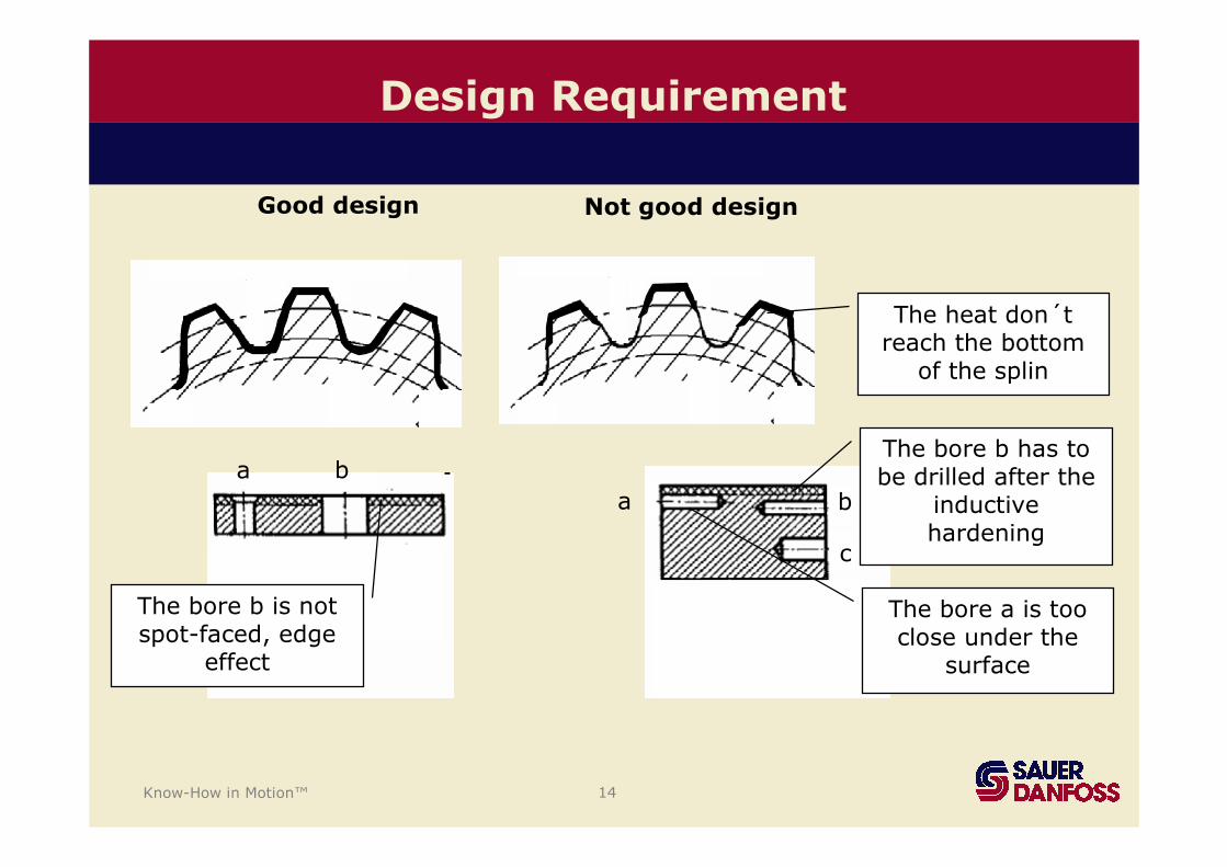
Design Requirement
Trough hardeningdistortion
OverheatingHardness cracks
Profile too thin
Diverse wall thickness distortion
The heat don´t reach the bottom
of the cut
Good design Not good design
Know-How in Motion™ 14
Design Requirement
The heat don´t reach the bottom
of the splin
a b
c
ba
The bore b is not spot-faced, edge
effect
The bore a is tooclose under the
surface
The bore b has to be drilled after the
inductivehardening
Good design Not good design
Know-How in Motion™ 15
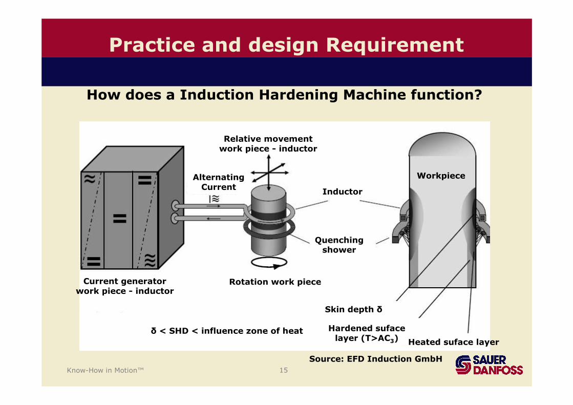
Source: EFD Induction GmbH
Practice and design Requirement
Relative movementwork piece - inductor
Rotation work pieceCurrent generatorwork piece - inductor
AlternatingCurrent
Inductor
Quenchingshower
Skin depth δ
Hardened sufacelayer (T>AC3) Heated suface layer
δ < SHD < influence zone of heat
Workpiece
How does a Induction Hardening Machine function?
Know-How in Motion™ 16
Practice and design Requirement
Advantages of the Induction Hardening
• Specific limited local hardening is possible
• No coarse grain formation results from long annealing
• Fine Martensite formation results from fast quenching
• There is almost no scale
• The repeatability of the hardness results is given
• The distortion can be kept very small (Hardness depth)
• The hardening times will be shorten
• The hardening machine can be located in the process line
Know-How in Motion™ 17
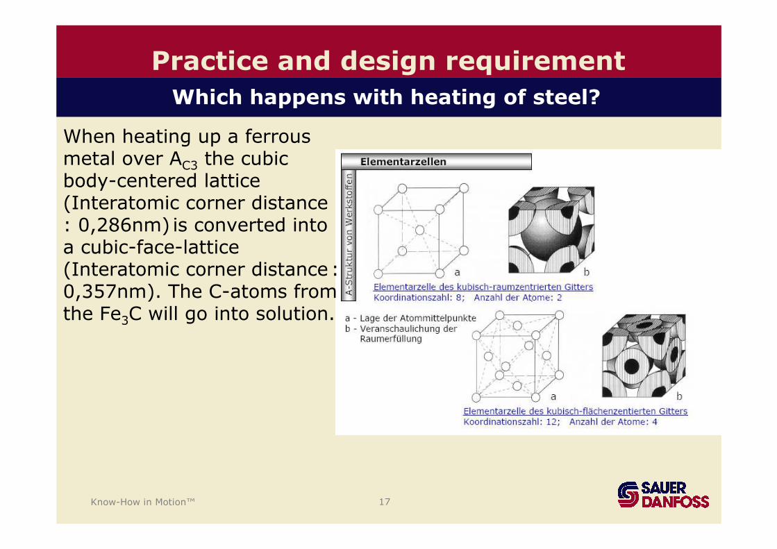
Practice and design requirement
When heating up a ferrousmetal over AC3 the cubicbody-centered lattice(Interatomic corner distance : 0,286nm) is converted intoa cubic-face-lattice(Interatomic corner distance: 0,357nm). The C-atoms fromthe Fe3C will go into solution.
Which happens with heating of steel?
Know-How in Motion™ 18
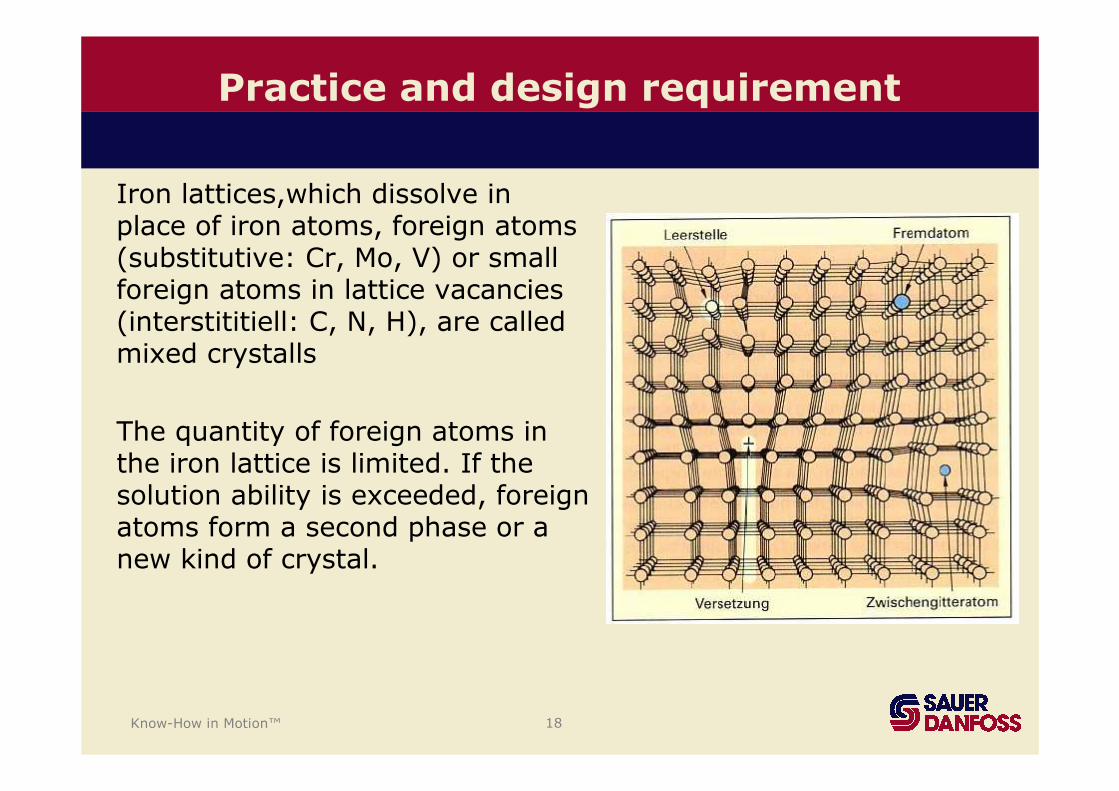
Practice and design requirement
Iron lattices,which dissolve in place of iron atoms, foreign atoms(substitutive: Cr, Mo, V) or smallforeign atoms in lattice vacancies(interstititiell: C, N, H), are calledmixed crystalls
The quantity of foreign atoms in the iron lattice is limited. If thesolution ability is exceeded, foreignatoms form a second phase or a new kind of crystal.

Know-How in Motion™ 19
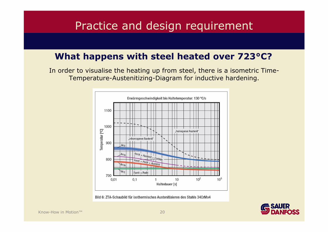
Practice and design requirement
What happens with steel heated over 723°C?
• Initially carbon is still unevenly distributed in the austenite(inhomogenous austenite). After longer holding the inhomogenousaustenite modifies itself into homogenous austenite
• First the structure condition of the pearlite changes. The iron carbides dissociate, and the cubic-body-centered lattice of theferrite changes with rising temperature into a cubic-face-centeredlattice.
• With alloyed steel the carbides disintegrates over 900°C.
• The structural constituent austenite develops. In the face-centered lattice substantially more carbon atoms on interstitial sites can beabsorbed, i.e., the carbon, which is set free by the decay of thecementite can be taken in solution.
Know-How in Motion™ 20
Practice and design requirement
In order to visualise the heating up from steel, there is a isometric Time-Temperature-Austenitizing-Diagram for inductive hardening.
What happens with steel heated over 723°C?
Know-How in Motion™ 21
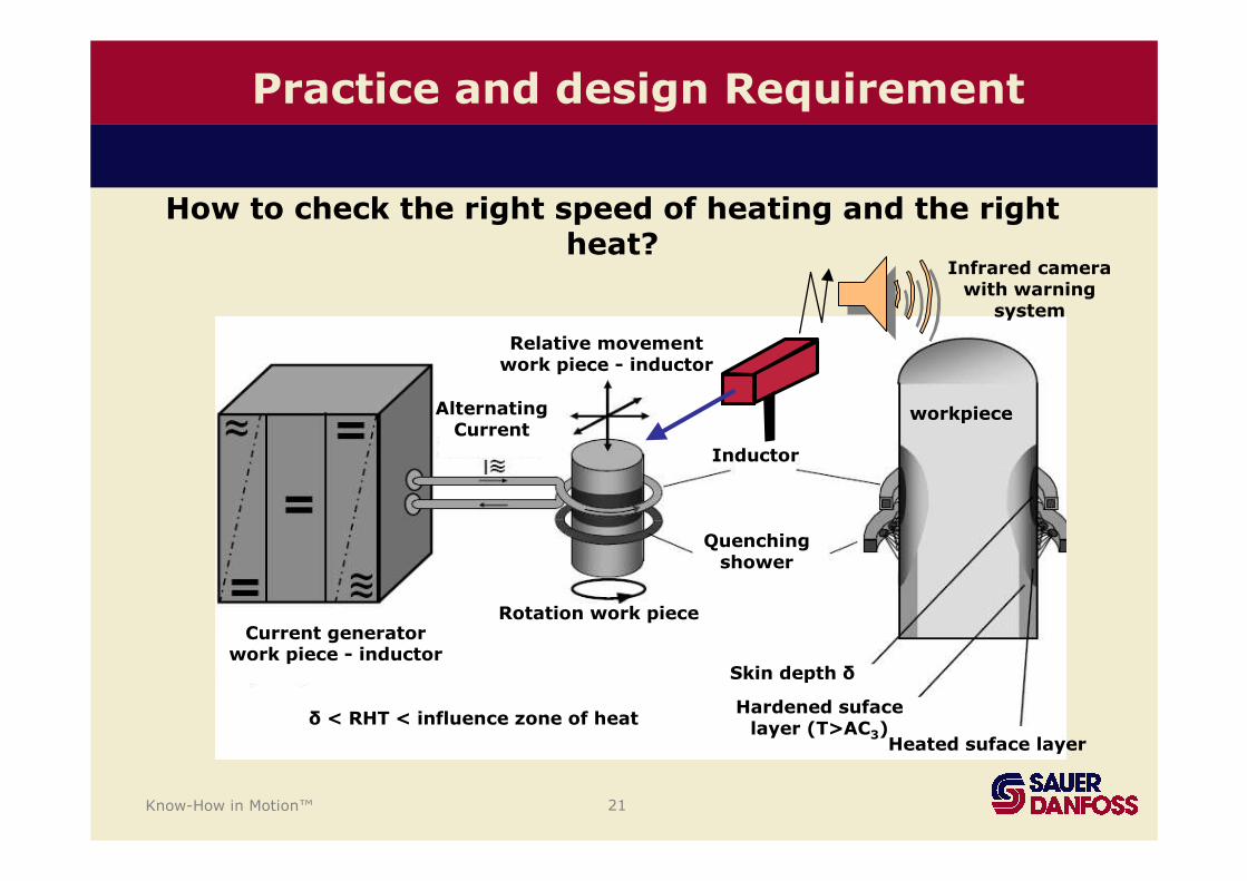
Practice and design Requirement
How to check the right speed of heating and the right heat?
Relative movementwork piece - inductor
Rotation work pieceCurrent generator
work piece - inductor
AlternatingCurrent
Inductor
Quenchingshower
Skin depth δ
Hardened sufacelayer (T>AC3)
Heated suface layer
δ < RHT < influence zone of heat
workpiece
Infrared camerawith warning
system
Know-How in Motion™ 22
Practice and design requirement
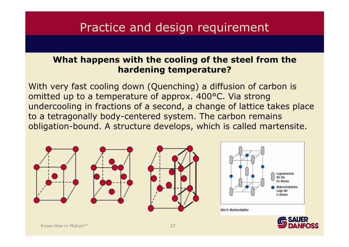
What happens with the cooling of the steel from thehardening temperature?
With very fast cooling down (Quenching) a diffusion of carbon isomitted up to a temperature of approx. 400°C. Via strongundercooling in fractions of a second, a change of lattice takes placeto a tetragonally body-centered system. The carbon remainsobligation-bound. A structure develops, which is called martensite.
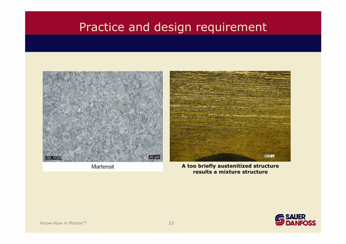
Know-How in Motion™ 23
Practice and design requirement
A too briefly austenitized structureresults a mixture structure
Know-How in Motion™ 24
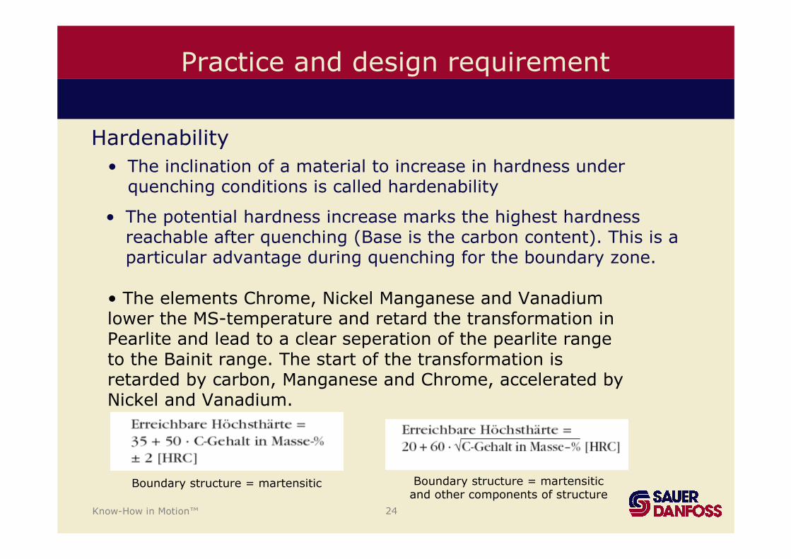
Hardenability
• The inclination of a material to increase in hardness underquenching conditions is called hardenability
• The potential hardness increase marks the highest hardnessreachable after quenching (Base is the carbon content). This is a particular advantage during quenching for the boundary zone.
• The elements Chrome, Nickel Manganese and Vanadium lower the MS-temperature and retard the transformation in Pearlite and lead to a clear seperation of the pearlite rangeto the Bainit range. The start of the transformation isretarded by carbon, Manganese and Chrome, accelerated byNickel and Vanadium.
Boundary structure = martensitic Boundary structure = martensiticand other components of structure
Practice and design requirement
Know-How in Motion™ 25
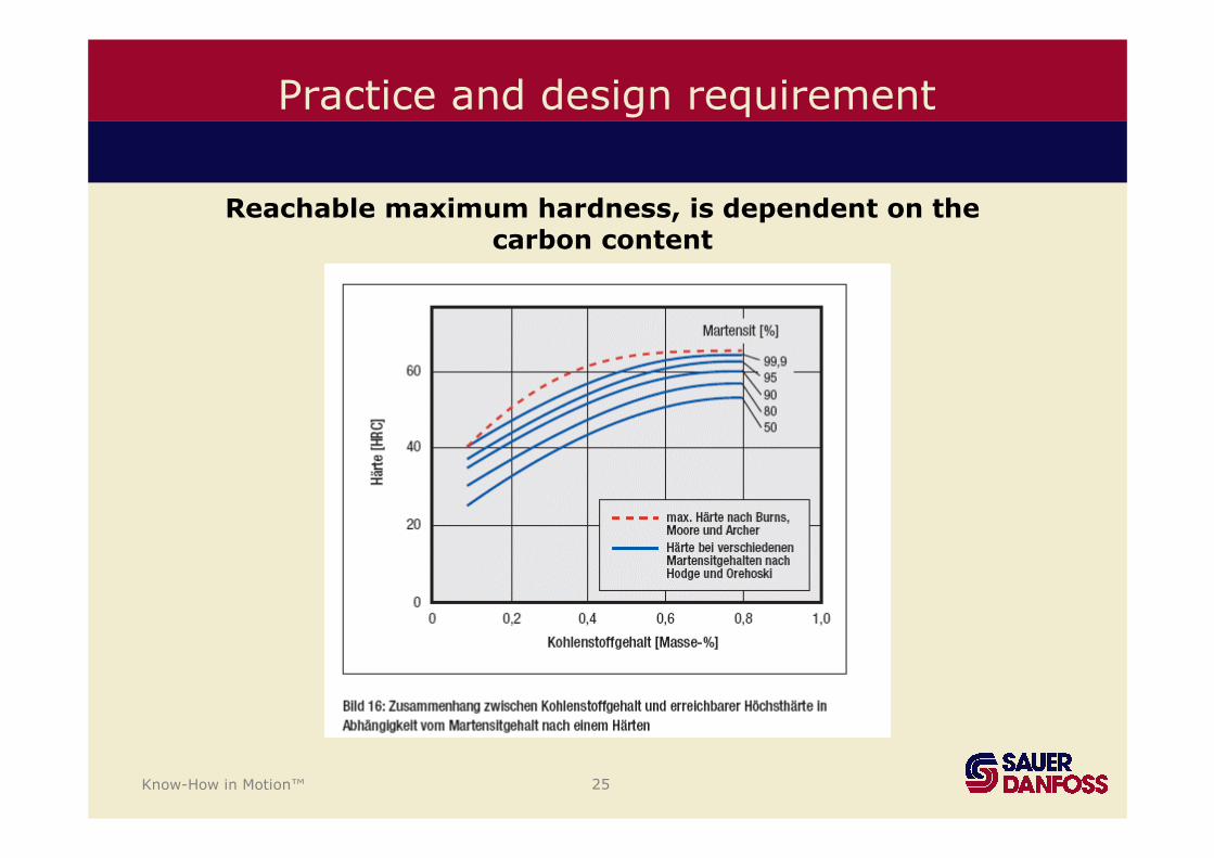
Reachable maximum hardness, is dependent on thecarbon content
Practice and design requirement
Know-How in Motion™ 26
• To retain the cooling of the material within the supercritical range, ifpossible. (100% Transforming in Martensite)
The tasks of the quenching medium are:
• To prevent too intensive cooling in the lower temperaturerange (distortion or even hardening cracks)
• To achieve a mild cooling of the material, so that the requiredproperties can be still attained after tempering.
Practice and design requirement
Know-How in Motion™ 27
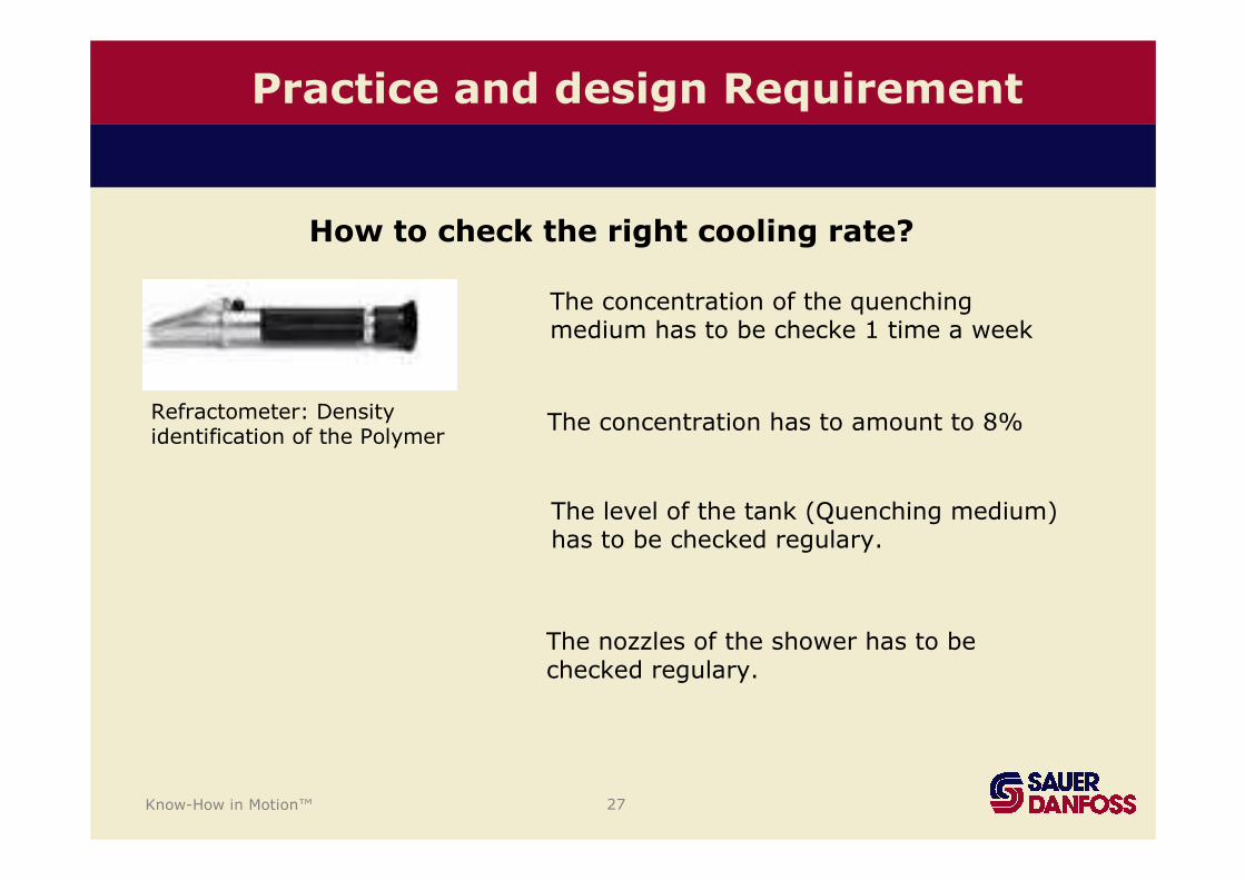
Practice and design Requirement
How to check the right cooling rate?
Refractometer: Densityidentification of the Polymer
The concentration of the quenchingmedium has to be checke 1 time a week
The concentration has to amount to 8%
The level of the tank (Quenching medium) has to be checked regulary.
The nozzles of the shower has to bechecked regulary.
Know-How in Motion™ 28
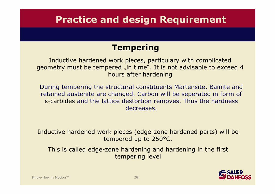
During tempering the structural constituents Martensite, Bainite and retained austenite are changed. Carbon will be seperated in form of ε-carbides and the lattice destortion removes. Thus the hardness
decreases.
Tempering
Inductive hardened work pieces (edge-zone hardened parts) will betempered up to 250°C.
This is called edge-zone hardening and hardening in the firsttempering level
Inductive hardened work pieces, particulary with complicatedgeometry must be tempered „in time“. It is not advisable to exceed 4
hours after hardening
Practice and design Requirement
Know-How in Motion™ 29
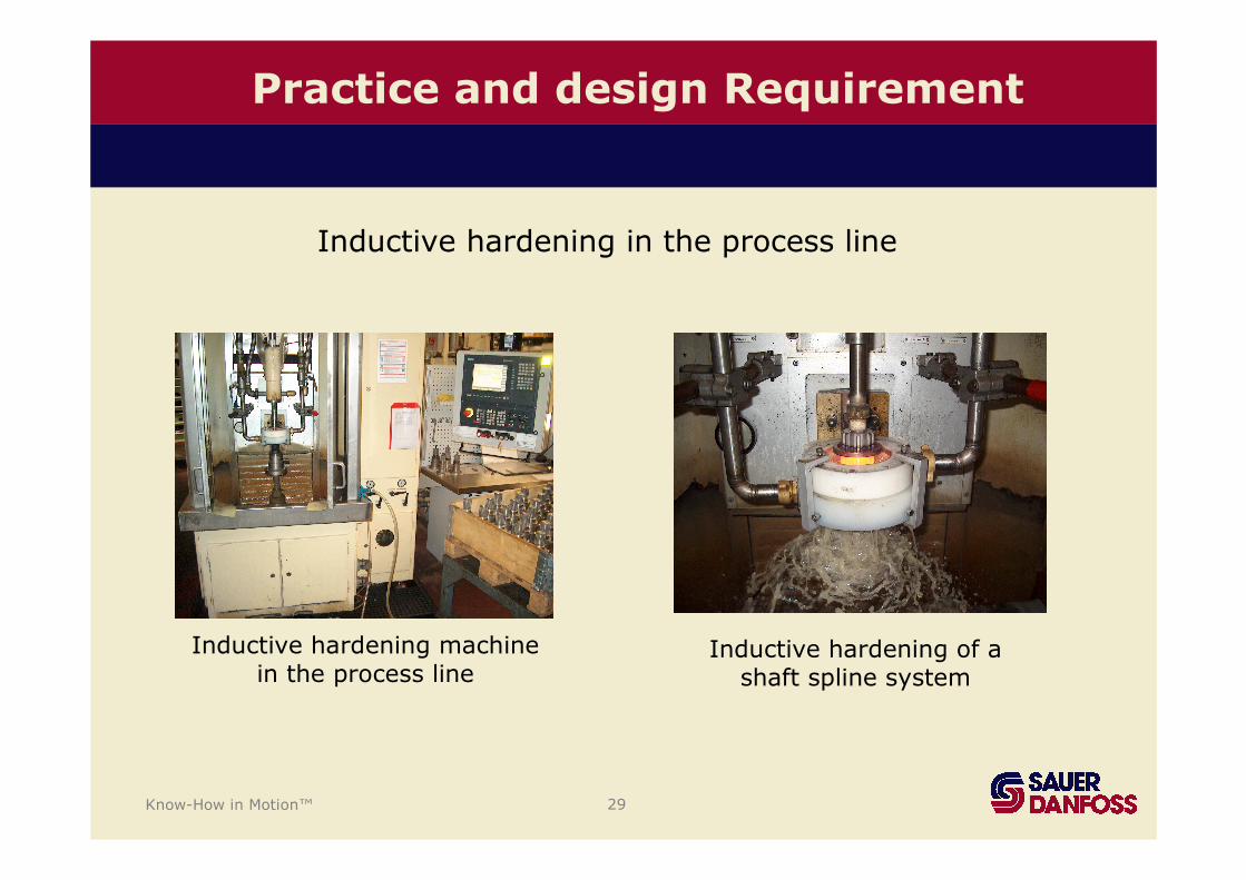
Practice and design Requirement
Inductive hardening machinein the process line
Inductive hardening of a shaft spline system
Inductive hardening in the process line
Know-How in Motion™ 30
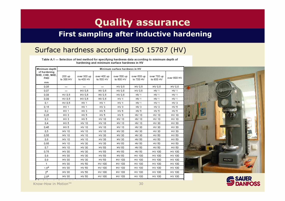
Surface hardness according ISO 15787 (HV)
Quality assuranceFirst sampling after inductive hardening
Know-How in Motion™ 31
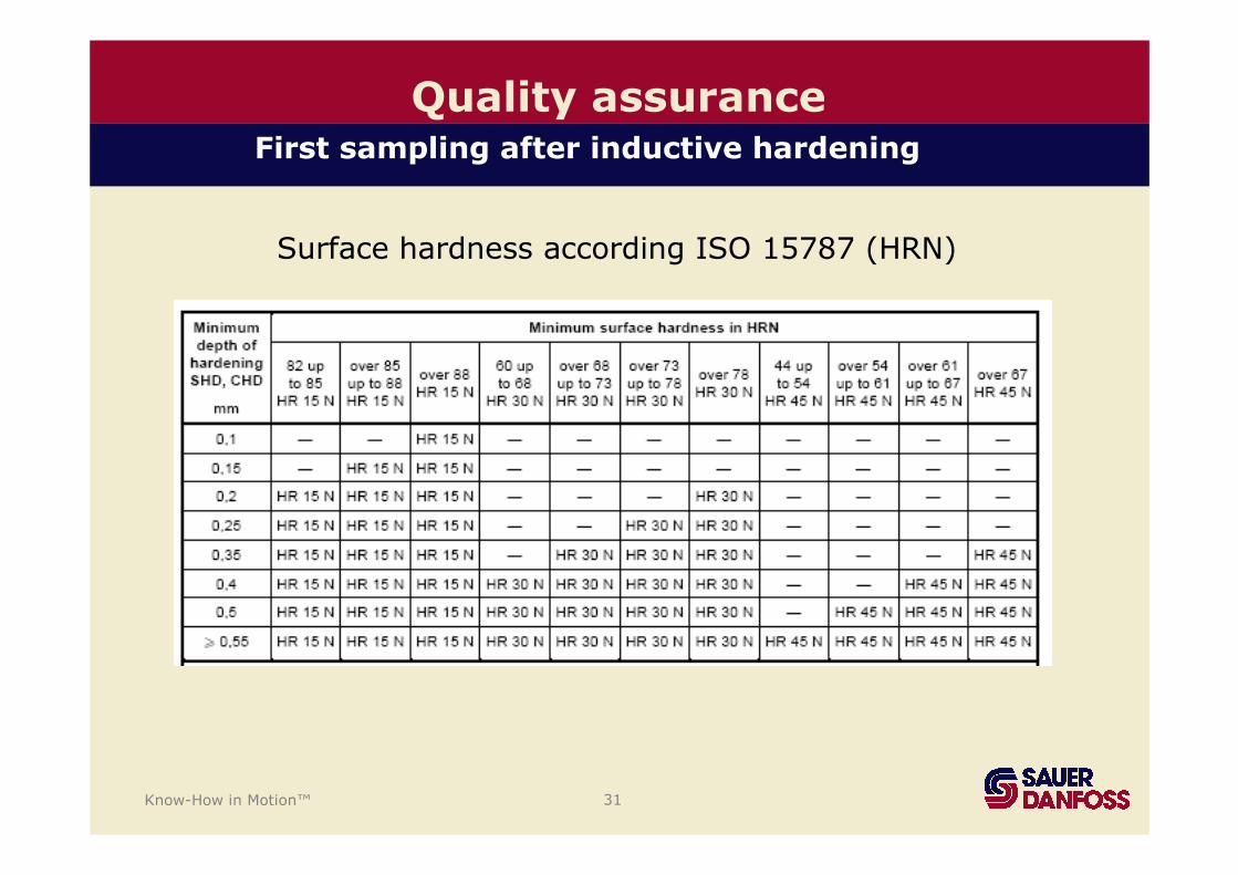
Quality assuranceFirst sampling after inductive hardening
Surface hardness according ISO 15787 (HRN)
Know-How in Motion™ 32
Quality assuranceFirst sampling after inductive hardening
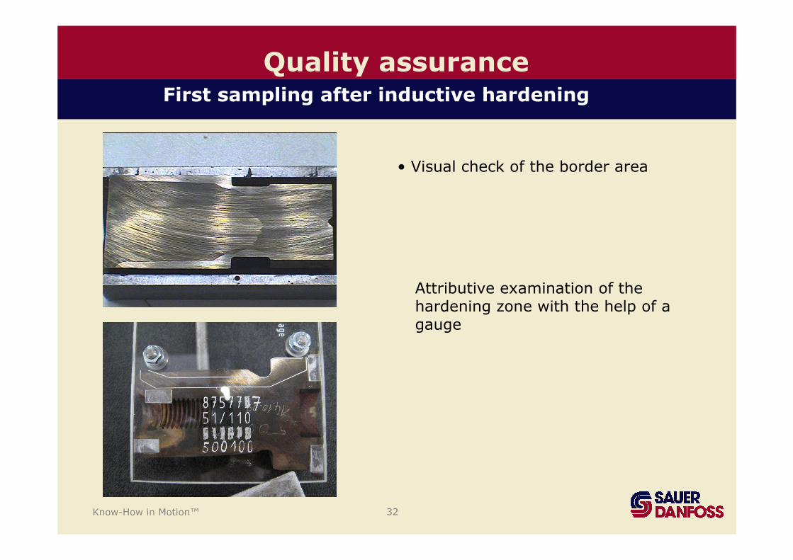
• Visual check of the border area
Attributive examination of thehardening zone with the help of a gauge
Know-How in Motion™ 33
Quality assurance
hard
ness
(HV1)
Distance from border (mm)
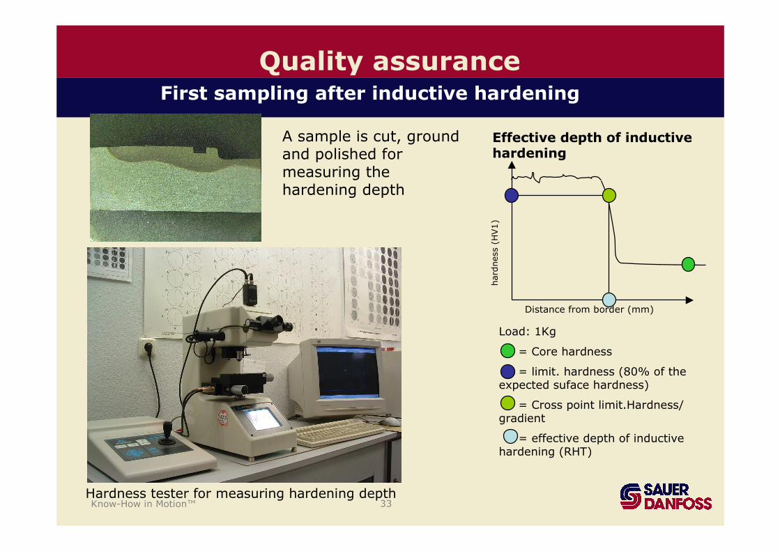
Effective depth of inductivehardening
Load: 1Kg
= Core hardness
= limit. hardness (80% of theexpected suface hardness)
= Cross point limit.Hardness/ gradient
= effective depth of inductivehardening (RHT)
A sample is cut, groundand polished formeasuring thehardening depth
Hardness tester for measuring hardening depth
First sampling after inductive hardening
Know-How in Motion™ 34
Quality assurance
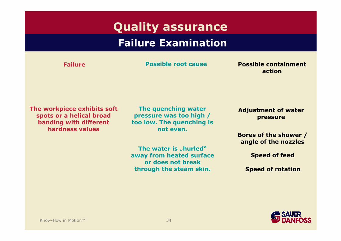
The workpiece exhibits soft spots or a helical broadbanding with different
hardness values
The quenching waterpressure was too high /
too low. The quenching isnot even.
The water is „hurled“ away from heated surface
or does not breakthrough the steam skin.
Adjustment of waterpressure
Bores of the shower / angle of the nozzles
Speed of feed
Speed of rotation
Possible containmentaction
Failure Possible root cause
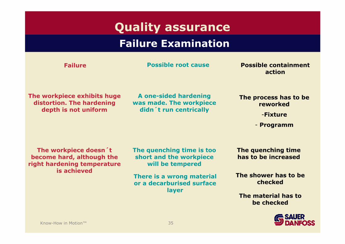
Failure Examination
Know-How in Motion™ 35
Quality assurance
Possible containmentaction
Failure Possible root cause
Failure Examination
The workpiece exhibits hugedistortion. The hardening
depth is not uniform
A one-sided hardeningwas made. The workpiece
didn´t run centrically
The process has to bereworked
-Fixture
- Programm
The workpiece doesn´t become hard, although the
right hardening temperatureis achieved
The quenching time is tooshort and the workpiece
will be tempered
There is a wrong material or a decarburised surface
layer
The quenching time has to be increased
The shower has to bechecked
The material has to be checked
Know-How in Motion™ 36
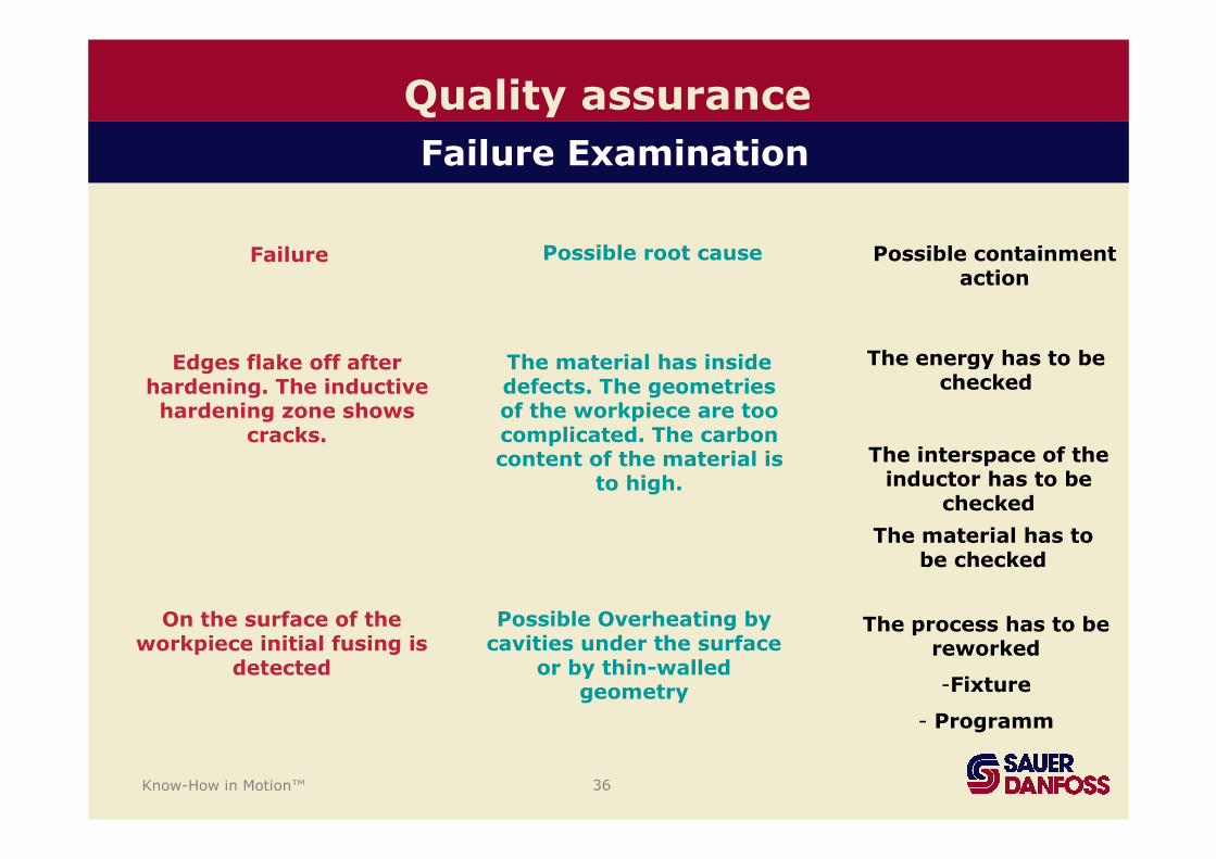
Quality assurance
Possible containmentaction
Failure Possible root cause
Edges flake off afterhardening. The inductivehardening zone shows
cracks.
The material has insidedefects. The geometriesof the workpiece are toocomplicated. The carboncontent of the material is
to high.
The energy has to bechecked
The interspace of theinductor has to be
checked
The material has to be checked
On the surface of theworkpiece initial fusing is
detected
Possible Overheating bycavities under the surface
or by thin-walledgeometry
The process has to bereworked
-Fixture
- Programm
Failure Examination
Know-How in Motion™ 37
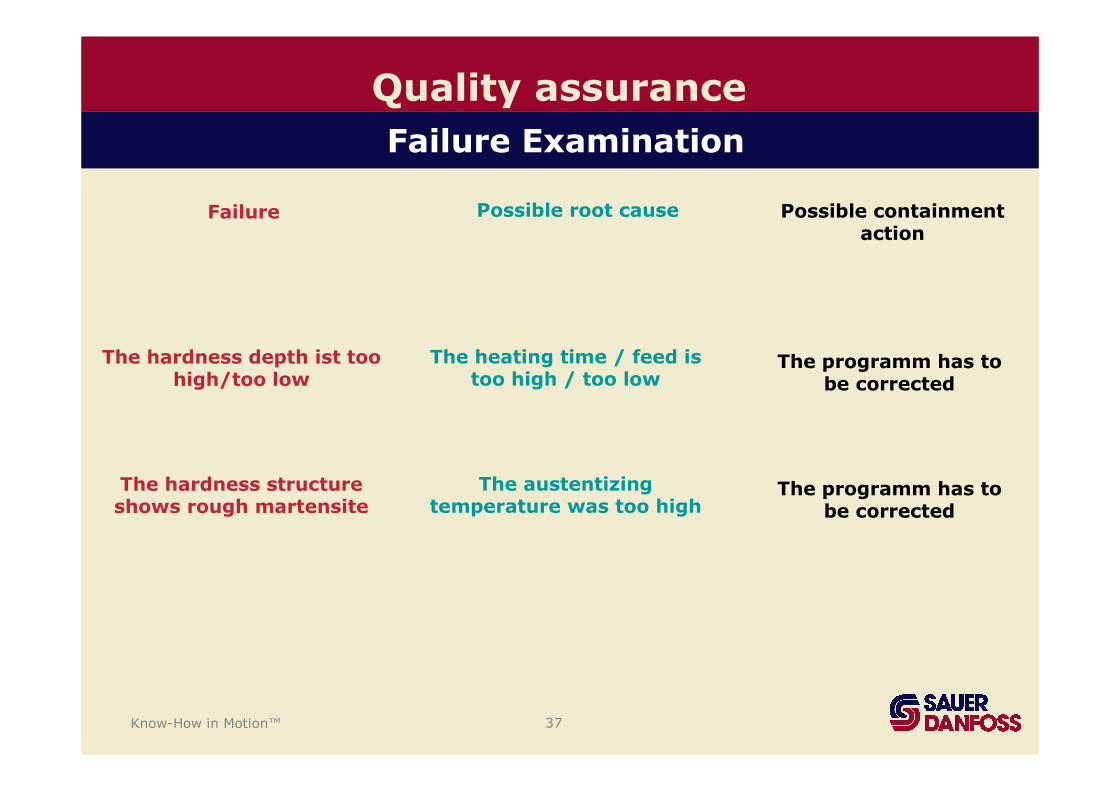
Quality assurance
Failure Examination
The hardness depth ist toohigh/too low
The heating time / feed istoo high / too low
The programm has to be corrected
Possible containmentaction
Failure Possible root cause
The hardness structureshows rough martensite
The austentizingtemperature was too high
The programm has to be corrected

Know-How in Motion™ 38
Conclusion
• Metallurgical basic knowledge must be present
- What happens with heating?
- What happens with quenching?
- Which material reacts in which way?
• A strict contract review „an absolute must have“ of a job order
• A well equipped induction hardening system, knowledge in the system and a strict quality system are likewise an important condition

Know-How in Motion™ 39
Thank you very muchfor your attention!