Embed Size (px)
Citation preview

Doc. Code
WLAN MIMO
Technical Whitepaper
Issue 01
Date 2012-09-15
HUAWEI TECHNOLOGIES CO., LTD.

Issue 01 (2012-09-15) Huawei Proprietary and Confidential
Copyright © Huawei Technologies Co., Ltd.
i
Copyright © Huawei Technologies Co., Ltd. 2012. All rights reserved.
No part of this document may be reproduced or transmitted in any form or by any means without prior written consent of Huawei Technologies Co., Ltd.
Trademarks and Permissions
and other Huawei trademarks are trademarks of Huawei Technologies Co., Ltd.
All other trademarks and trade names mentioned in this document are the property of their respective holders.
Notice
The purchased products, services and features are stipulated by the contract made between Huawei and
the customer. All or part of the products, services and features described in this document may not be
within the purchase scope or the usage scope. Unless otherwise specified in the contract, all statements,
information, and recommendations in this document are provided "AS IS" without warranties, guarantees or representations of any kind, either express or implied.
The information in this document is subject to change without notice. Every effort has been made in the
preparation of this document to ensure accuracy of the contents, but all statements, information, and recommendations in this document do not constitute a warranty of any kind, express or implied.
Huawei Technologies Co., Ltd.
Address: Huawei Industrial Base
Bantian, Longgang
Shenzhen 518129
People's Republic of China
Website: http://www.huawei.com
Email: [email protected]

WLAN MIMO
Technical Whitepaper Contents
Issue 01 (2012-09-15) Huawei Proprietary and Confidential
Copyright © Huawei Technologies Co., Ltd.
ii
Contents
1 Overview ................................................................................................................................... 3
1.1 Definition .................................................................................................................................................. 3
1.2 Purpose ..................................................................................................................................................... 3
2 Principles ................................................................................................................................... 4
2.1 MIMO Technology .................................................................................................................................... 4
2.1.1 History ............................................................................................................................................. 4
2.1.2 MIMO Principles .............................................................................................................................. 4
2.2 Spatial Diversity ........................................................................................................................................ 6
2.2.1 Receive Diversity ............................................................................................................................. 6
2.2.2 Transmit Diversity ............................................................................................................................ 6
2.2.3 MISO and SIMO Gain Analysis ........................................................................................................ 8
2.3 TxBF ......................................................................................................................................................... 8
2.3.2 TxBF Principles ................................................................................................................................ 9
3 Summary ................................................................................................................................. 12

WLAN MIMO
Technical Whitepaper 1 Overview
Issue 01 (2012-09-15) Huawei Proprietary and Confidential
Copyright © Huawei Technologies Co., Ltd.
3
1 Overview
1.1 Definition The multiple-input and multiple-output (MIMO) technology is introduced in the IEEE
802.11n protocol and brings the wireless local area network (WLAN) technology into a
multi-antenna era.
Multiple antennas are used at both the transmit end and the receive end to transmit and
receive signals. The MIMO technology reduces error codes and speeds up data transmission
to improve service quality.
1.2 Purpose In a traditional WLAN system, both an AP and a user device use only one antenna. Signals are
transmitted through the 802.11a/b/g protocol. The maximum signal transmission rate is 54
Mbit/s and can hardly be increased anymore. With the increasing popularity and application
of the WLAN technology, the rate of wireless communication needs to be increased
substantially.
The MIMO technology, which is used in the 802.11n protocol, increases the rate of WLAN
signal transmission greatly, and satisfies growing requirements on bandwidth and signal
quality.

WLAN MIMO
Technical Whitepaper 2 Principles
Issue 01 (2012-09-15) Huawei Proprietary and Confidential
Copyright © Huawei Technologies Co., Ltd.
4
2 Principles
2.1 MIMO Technology
2.1.1 History
The MIMO technology is a breakthrough of the smart antenna technology in the field of
wireless mobile communications. The MIMO technology increases the channel capacity and
spectrum efficiency by multiple without changing the bandwidth. It is a key technology in
new-generation mobile communications systems.
What is the history of the MIMO technology?
The MIMO technology has a long history dating back to 1908 when Marconi first used it to
reduce fading. In the 1970s, the MIMO technology was recommended in communications
systems. In the 1990s, scientists in the AT&T Bell Laboratories laid a foundation for the
application of MIMO in wireless mobile communications systems.
In 1995, Telatar analyzed MIMO capacity in a fading environment. In 1996, Foschini
proposed a new MIMO processing algorithm Diagonal-Bell Laboratories Layered
Space-Time (D-BLAST). In 1998, Tarokh analyzed space-time codes for high data rate
wireless communication in his paper composed together with other two scholars. In 1998,
Wolniansky and other scientists established a MIMO experimental system using Vertical-Bell
Laboratories Layered Space-Time (V-BLAST).
In an indoor experiment, a spectrum utilization of 20 bit/Hz was achieved. The 20 bit/Hz
spectrum utilization was hard to achieve in common communications systems. The preceding
work attracted worldwide attention and promoted the fast development of the MIMO
technology.
2.1.2 MIMO Principles
In traditional WLAN communications systems, both an AP end and a user end use only one
antenna. The antenna system is named single-input and single-output system (SISO).
C.E.Shannon proposed the following formula to calculate channel capacity in a SISO system.
C = B*log 2 (1 + S/N)
In the preceding formula, B stands for bandwidth of a channel and S/N stands for
signal-to-noise-ratio.
The formula for bandwidth utilization is as follows:

WLAN MIMO
Technical Whitepaper 2 Principles
Issue 01 (2012-09-15) Huawei Proprietary and Confidential
Copyright © Huawei Technologies Co., Ltd.
5
Ω = log 2 (1 + S/N)
The preceding formula calculates the maximum rate of reliable communication in a channel
with noises. Other technologies cannot provide a rate larger than the maximum rate no matter
what modulation methods and channel coding methods are used.
Figure 2-1 SISO wireless channel system
Tx Rx
Ω= log(1+S/N)
Install multiple antennas at the transmit or receive end. The antennas are considered
independent of each other when antennas are far away from each other. Multiple independent
channels are therefore constructed at the transmit or receive end. If a transmit end has N
transmit antennas, a receive end has M receive antennas, and each stream of the M x N data
streams are independent of each other in a wireless link, the system capacity increases with
the number of antennas according to the information theory. In a MIMO system, the channel
capacity can be calculated using the following formula:
C ≈ min(M,N)* log 2 (1 + S/N)
As shown in the formula, under ideal conditions, if the number of antennas is not limited, a
MIMO system can provide infinite channel capacity.
Figure 2-2 MIMO wireless channel system
Tx RxChannel
matrix
Transmit antenna Receive antenna
As shown in Figure 2-2, a MIMO system contains N transmit antennas and M receive
antennas. The transmit data stream is divided into N substreams, and is transmitted through N
antennas at the same time after modulation. Through scattering transmission in wireless
channels, the parallel substreams are transmitted to the receiver from different paths and are

WLAN MIMO
Technical Whitepaper 2 Principles
Issue 01 (2012-09-15) Huawei Proprietary and Confidential
Copyright © Huawei Technologies Co., Ltd.
6
received by M receive antennas. The receiver processes the substreams and restores the
original data stream.
Compared with traditional antenna systems, MIMO wireless communications systems
transmit signals in multiple paths and construct multiple parallel transmission channels. Using
the space-time block coding (STBC) technique, MIMO achieves transmit adversity and
receive adversity, provides spatial multiplexing gain and spatial diversity gain, and improves
channel capacity through parallel transmission channels. The MIMO technology is the most
promising technology among emerging wireless communication technologies, and creates a
significant way to high-speed transmission in wireless communications systems.
Note that in the MIMO technology:
The parallel N substreams are transmitted at the same time from the transmit end. All transmit
signals use the same bandwidth and no extra bandwidth is needed, improving available
bandwidth. Therefore, the MIMO technology maintains the total transmit power of the
transmit end, achieves best power allocation without increasing the transmit power of the
system.
2.2 Spatial Diversity
MIMO provides two mainstream technologies for wireless channels: receive diversity and
transmit diversity.
2.2.1 Receive Diversity
In receive diversity, the receiver uses more antennas than the transmitter (M > N). If the
transmitter uses only one antenna (N = 1), the receive diversity is called SIMO. The following
figure shows the simplest receive diversity that uses two receive antennas and one transmit
antenna (SIMO, 1x2).
Figure 2-3 SIMO antenna configuration
Tx Rx
SIMO requires no special coding technique and is easy to implement. The receiver needs only
two radio channels for receiving two independent loss signals transmitted. The signal noise
ratio (SNR) of received signals can be increased using methods such as diversity selection and
maximal ratio combining (MRC). Diversity selection presents the strongest signal, while
MRC combines two signals.
2.2.2 Transmit Diversity
In transmit diversity, the transmitter uses more transmit antennas than the receiver (M < N).
When the receiver uses only one antenna, the transmit diversity is called MISO. The

WLAN MIMO
Technical Whitepaper 2 Principles
Issue 01 (2012-09-15) Huawei Proprietary and Confidential
Copyright © Huawei Technologies Co., Ltd.
7
following figure shows simplest transmit diversity that uses two transmit antennas and one
receive antenna (MISO, 2x1).
Figure 2-4 MISO antenna configuration
Tx Rx
As shown in the figure, two antennas in the MISO system transmit corresponding data of the
same signal. MISO uses the space time coding (STC) technology to improve the signal
capability to prevent attenuation and increase the channel capacity.
STC integrates the characteristics of diversity, coding, and modulating. The most attractive
feature of STC is that it achieves space division multiple access (SDMA) by combing coding
and matrix technologies. This improves the capability of the system to prevent signal
attenuation. In addition, STC provides high quality data transmission at high rate for the
transmit and receive diversity. In contrast to the non-STC coding system, the STC system
supports high coding gain while ensuring bandwidth, improving the anti-interference and
anti-noise capabilities. WLAN 802.11n uses space-time block coding (STBC) technology.
STBC is a simple and optional transmit diversity mechanism defined in 802.11n. It provides a
diversity gain that amounts to the gain obtained through MRC. However, if the total transmit
power is limited, STBC is not competitive because STBC provides a little gain. STBC enables
a low-cost device that requires low power and low data transmission rate to obtain high link
performance using the assigned wireless channels.
As shown in the preceding figure, STBC uses the Alamouti algorithm. Signals processed
using orthogonal coding are transmitted over two antennas. These signals are transmitted
independently and easy to differentiate at the receiver. Therefore, signals can be obtained by
the receiver with only linear processing.
Figure 2-5 STBC implementation
Source ModulateSTBC
coder

WLAN MIMO
Technical Whitepaper 2 Principles
Issue 01 (2012-09-15) Huawei Proprietary and Confidential
Copyright © Huawei Technologies Co., Ltd.
8
The preceding figure shows the STBC implementation. The binary bit information sent from
the source is modulated to M = 2m
symbols. STBC coder maps two continuous symbols to
signal matrix based on the following formula:
X=[*
12
*
21
xx
xx
]
Signal [ 1x,
*
2x] and signal [ 2x ,
*
1x] are mutually orthogonal. In the first specified
time slot, two signals in each group are transmitted simultaneously. The signal sent from
antenna 1 is 1x and the signal sent from antenna 2 is 2x
. In the next time slot, signal
*
2x is sent from antenna 1 and signal
*
1x is sent from antenna 2.
The STBC using Alamouti algorithm has been applied to multiple-antenna systems. If STBC
is used, the transmitter must inform the receiver that signals are processed using STBC so that
the receiver can implement corresponding decoding on the received signals.
2.2.3 MISO and SIMO Gain Analysis
MISO and SIMO belong to MIMO antenna system. The MIMO capacity is calculated based
on the following formula:
The increase of channel capacity depends on the minimum values of M and N. Therefore, the
channel capacity is increased a little using SIMO and MISO.
Actually, the channel capacity provided by SIMO and MISO is slightly higher than that
provided by SISO.
2.3 TxBF
What has been discussed above is the simultaneous transmission of the same signals in a
multi-antenna system, which brings undesired space black holes. Each data copy is
transmitted by a different antenna. After reaching the receive antenna through its specific path,
each copy is reflected by different walls and devices. If two paths lead to the same location,
whose signal loss is equal but phases are reversed, they will offset each other. A space black
hole is therefore generated.

WLAN MIMO
Technical Whitepaper 2 Principles
Issue 01 (2012-09-15) Huawei Proprietary and Confidential
Copyright © Huawei Technologies Co., Ltd.
9
Reversed phases resulting in space black holes
Tx
Rx
A
B
A
B
However, effective transmit beamforming (TxBF) brings a completely different situation. If
the phase of each path is compensated at the starting point of the transmit antenna, multiple
data copies have the same phase when reaching the receive antennas. Instead of offsetting
each other, two paths superpose with each other, improving transmission performance to the
most. The auto-sensing TxBF described in the 802.11n standard refers exactly to this type of
TxBF. It significantly improves the signal quality on the receive end.
2.3.1 TxBF Principles
TxBF facilitates reception by weighting transmission signals. The weighted coefficient is
obtained based on the transmission environment and channel state information (CSI). Based
on the method of obtaining transmitter weighting matrix, TxBF is classified into explicit
beamforming and implicit beamforming.
Explicit Beamforming
Explicit beamforming is an optional mode defined in the 802.11n standard and requires the
support of the client (receiver). In an explicit feedback mechanism, the TxBF STA is the STA
that sends probe packets. STA A sends a detection packet to STA B, and STA B returns CSI or
beamforming weight to STA A. According to this feedback, STA A sends a packet to STA B
through TxBF.
Three explicit feedback formats are defined in the 802.11n standard: CSI, non-compressed
beamforming weight, and compressed beamforming weight. The quantities of rows and
columns in the CSI matrix and weight matrix respectively correspond to the number of
antennas that receive detection packets and the HT-LTF quantity of the detection packets. If
the TxBF transmit end has four antennas, the transmit hardware is required to send four
spatial flows and the client (receiver) must support detection of four transmit antennas, while
the mainstream chip currently supports only three antennas at most.
The explicit feedback, however, lowers the system efficiency. The 802.11n standard
introduces quantization and subcarrier grouping technologies to bring down system costs.
The explicit beamforming provides the most precise information about channels. Once
available (requires support of terminals), it can increase the throughput to the most and ensure
link stability. Theoretically, the maximum possible beamforming gain on a flat channel is as
follows:
WLAN MIMO
Technical Whitepaper 2 Principles
Issue 01 (2012-09-15) Huawei Proprietary and Confidential
Copyright © Huawei Technologies Co., Ltd.
10
G TxBF = 10*lg (Tx)
When there are three transmit antennas, the maximum BF gain is 4.77 dB; when there are four
transmit antennas, the maximum BF gain is 6.02 dB, with an increase of 1.25 dB. The gain
obtained in practice, however, is much lower. Measures designed to reduce system costs for
feedback, such as quantization, subcarrier grouping, and compression, decrease the gain. In
addition, the actual channel is frequency-selective rather than flat, so the effect of the beam
convergence is limited. The channel environment changes with time, resulting in the feedback
delay or the delay from measuring CSI to applying beams, which also degrades the channel
performance. Therefore, compared to 3Tx, the practical gain of 4Tx increases only by a
maximum of 0.75 dB.
Implicit Beamforming
Implicit beamforming is Cisco's ClientLink or ClientLink 2.0 that is a STA-free beamforming
technology. An AP can measure the CSI of a channel at any time when STAs transmit signals.
The CSI helps the AP return the data with least attenuation to STAs. It seems that this
beamforming mode is free of STA limitations. This only tells part of the story.
Based on the electromagnetic equivalence principle, implicit beamforming allows transmit
and receive beams on an antenna to use the same electromagnetic field. In the 802.11n
standard, carriers with the same frequency are applied to two directions of a link. Ideally, the
CSI measured on any end is the same when the coefficient affecting radios are equivalent on
devices at both ends of the link. However, interference is not equivalent on the two ends. The
channel between the digital basebands of devices includes the filter, power amplifier (PA),
and low noise amplifier (LNA). The RF distortions of these devices are not equivalent.
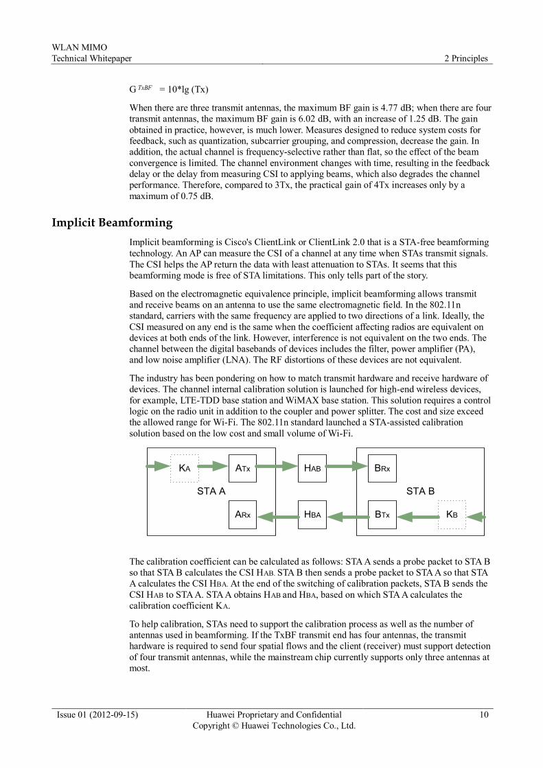
The industry has been pondering on how to match transmit hardware and receive hardware of
devices. The channel internal calibration solution is launched for high-end wireless devices,
for example, LTE-TDD base station and WiMAX base station. This solution requires a control
logic on the radio unit in addition to the coupler and power splitter. The cost and size exceed
the allowed range for Wi-Fi. The 802.11n standard launched a STA-assisted calibration
solution based on the low cost and small volume of Wi-Fi.
STA A STA B
KA BRxATx HAB
KBBTxHBAARx
The calibration coefficient can be calculated as follows: STA A sends a probe packet to STA B
so that STA B calculates the CSI HAB. STA B then sends a probe packet to STA A so that STA
A calculates the CSI HBA. At the end of the switching of calibration packets, STA B sends the
CSI HAB to STA A. STA A obtains HAB and HBA, based on which STA A calculates the
calibration coefficient KA.
To help calibration, STAs need to support the calibration process as well as the number of
antennas used in beamforming. If the TxBF transmit end has four antennas, the transmit
hardware is required to send four spatial flows and the client (receiver) must support detection
of four transmit antennas, while the mainstream chip currently supports only three antennas at
most.

WLAN MIMO
Technical Whitepaper 2 Principles
Issue 01 (2012-09-15) Huawei Proprietary and Confidential
Copyright © Huawei Technologies Co., Ltd.
11
Some Wi-Fi device providers claim that their designs are independent of STA assistance on
calibration. This is infeasible actually. The Wi-Fi features make it impossible to deploy radio
calibration channels on the Wi-Fi radio board. The hardware match between transmit and
receive devices can be accomplished only by integrating the transceiver on a chip. The Tx and
Rx links must be configured the same on the chip. However, the channels of external radio
components (such as PA and LNA) are independent, and consistency between their channels
cannot be ensured. In addition, the RF distortions of active components may change
inconsistently due to changes in the temperature in the current circuit, carrier frequency, or
gain.
The RF channel consistency cannot be ensured if internal or external assistant calibration is
not performed, which cannot ensure intentional beamforming. Unintentional beamforming
cannot only provide required gains, but may also offset the signal gains.
To sum up, implicit beamforming applies to APs on a BSS network where at least a STA
supports the assistant calibration function. The STA periodically help the AP perform
calibration, and the calibrated AP can send intentional beamforming spatial streams to all
802.11n STAs regardless of whether they support beamforming and 802.11a/g STAs
supporting only the single spatial stream on a BSS network. The increase in gains is to be
tested in practice.

WLAN MIMO
Technical Whitepaper 3 Summary
Issue 01 (2012-09-15) Huawei Proprietary and Confidential
Copyright © Huawei Technologies Co., Ltd.
12
3 Summary
This document analyzes the MIMO technology in WLAN based on the Shannon's notion of
channel capacity. The analysis result shows that the WLAN MIMO technology greatly
improves the channel capacity and the increase of transmit and receive antennas helps
improve system performance and reduce BER.
A single transmit or receive antenna contributes a little to increase in the system gain. How to
obtain and leverage the CSI is to be researched.
In practice, a better choice is required for balance in addition to the system complexity and
system performance.