Embed Size (px)
Citation preview
WLA300 Rev170606
1
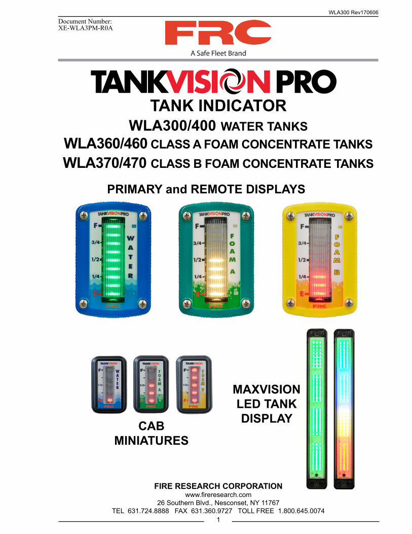
TANK INDICATORWLA300/400 WATER TANKS
WLA360/460 CLASS A FOAM CONCENTRATE TANKSWLA370/470 CLASS B FOAM CONCENTRATE TANKS
Document Number:XE-WLA3PM-R0A
PRIMARY and REMOTE DISPLAYS
MAXVISION LED TANK DISPLAYCAB
MINIATURES
FIRE RESEARCH CORPORATIONwww.fireresearch.com
26 Southern Blvd., Nesconset, NY 11767TEL 631.724.8888 FAX 631.360.9727 TOLL FREE 1.800.645.0074
WLA300 Rev170606
2
CONTENTSTable of Contents
CONTENTS ................................................................................................................ 2List of Figures ........................................................................................................ 3
INTRODUCTION ...................................................................................................... 4Overview ................................................................................................................ 4Features .................................................................................................................. 4Specifications ......................................................................................................... 6
GENERAL DESCRIPTION ....................................................................................... 7Components ........................................................................................................... 7
INSTALLATION ........................................................................................................ 9Install Display Module........................................................................................... 9Install Cab Miniature Display ................................................................................ 9Install Pressure Sensor ......................................................................................... 11Install Pressure/Vacuum Foam Tank Vent ........................................................... 13Install MaxVision LED Tank Display .................................................................. 15Program MaxVision LED Tank Display .............................................................. 15Install Remote Light Driver ................................................................................. 19Install Buzzer ....................................................................................................... 19
OPERATION ............................................................................................................ 20Options ................................................................................................................. 20
CALIBRATION ........................................................................................................ 22Overview .............................................................................................................. 22
PROGRAMMING CODES ...................................................................................... 23Calibration and Tank Level Correction ................................................................ 23Non-Linear Calibration ........................................................................................ 24Linear Calibration ................................................................................................ 25Full Tank Correction (Code 55) ........................................................................... 26
DIAGNOSTICS ........................................................................................................ 27COLOR PATTERN SELECTION ............................................................................ 29
Warning and Control Level Adjustment .............................................................. 30Brightness Adjustment ......................................................................................... 32Primary and Remote Synchronization ................................................................. 32
WIRING .................................................................................................................... 33Primary Display (WLA3XX/WLA4XX)............................................................. 33
WIRING .................................................................................................................... 34Primary Display Rear View (WLA3XX/WLA4XX) ........................................... 34Remote Displays (WLA3XX/WLA4XX) ........................................................... 35Cab Miniature and MaxVision LED Displays ..................................................... 36Remote Light Driver ............................................................................................ 37
WLA300 Rev170606
3
List of FiguresFigure 1. Display Module Mounting Dimensions ................................................... 10Figure 2. Cab Miniature Display Mounting Dimensions ......................................... 10Figure 3. Pressure Sensor ......................................................................................... 12Figure 4. Pressure/Vacuum Foam Tank Vent ........................................................... 14Figure 5. MaxVision Color Pattern Programming ................................................... 17Figure 6. MaxVision LED Display Mounting Dimensions ..................................... 18Figure 7. Remote Light Driver ................................................................................. 19Figure 8. Diagnostics - Faults .................................................................................. 27Figure 9. Diagnostics - Warnings ............................................................................. 28Figure 10. Color Pattern Selection ........................................................................... 29Figure 11. Diagnostics - Warnings ........................................................................... 30Figure 12. Primary Display Wiring ......................................................................... 33Figure 13. Primary Display Wiring (Rear View) ..................................................... 34Figure 14. Remote Display Wiring (WLA3XX/WLA4XX) ................................... 35Figure 15. Cab Miniature and LED Display Wiring ............................................... 36Figure 16. Remote Light Driver Wiring .................................................................. 37Figure 17. Typical System Configuration WLA3XXX............................................ 38Figure 18. Typical System Configuration WLA4XXX............................................ 39Figure 19. Clean and Inspect Pressure/Vacuum Foam Tank Vent ........................... 40Figure 20. WLA300 Parts List ................................................................................. 41Figure 21. WLA400 Parts List ................................................................................. 42
Typical System Configuration WLA3XX ............................................................ 38Typical System Configuration WLA4XX ............................................................ 39
CLEAN/INSPECT PRESSURE/VACUUM FOAM TANK VENT ......................... 40PARTS LIST ............................................................................................................. 41
WLA300 Rev170606
4
INTRODUCTION
OverviewThe FRC TankVisionPro indicator shows the actual volume of liquid in a tank. The
liquid in the tank exerts a pressure that is measured by a sensor. As the amount of liquid changes, the pressure it exerts on the sensor changes proportionally. The pressure change is used to calculate the exact volume of liquid in the tank. The TankVisionPro can be calibration to accurately display the volume of liquid in tanks of all shapes and sizes.
The display module is able to communicate with other display modules over the FRC datalink. This allows for one master display module to control multiple displays. The module also provides an output for cab miniature displays, remote light drivers, and a low level warning buzzer.
The TankVisionPro indicator is a unique design made up of an extended wide view lens with 9 or 10 super bright LEDs (depending on the chosen configuration) mounted behind it. This allows the display to be visible and clearly read from all line-of-sight angles for a full 180 degrees.
The pressure/vacuum foam tank vent is supplied for use on foam concentrate storage tanks. These tanks should remain closed to the atmosphere. The FRC vent enables the tank to compensate for changes in pressure or vacuum due to thermal expansion, filling, or when withdrawing foam concentrate from the tank.
The MaxVision LED tank display provides a remote, wide angle view of how much water or foam concentrate is left in the tank in fractional 1/8 tank eight level increments.
The remote light driver provides the option to have four 60 watt remote lights controlled by the TankVisionPro to show full, 3/4, 1/2, and 1/4 tank.
FeaturesSelf-Calibrating for Any Shape or Size TankVisual Warnings At 1/4 and Almost Empty Tank ConditionsMultiple Remote DisplaysPressure/Vacuum Foam Tank Vent for Sealed Foam TanksColor Coded for Water, Class A, or Class B FoamSelf-Diagnostic CapabilitiesCab Miniature Display (Optional)MaxVision LED Tank Display (Optional)Remote Light Driver (Optional)Low Level Warning Buzzer (Optional)Tank Thin Wall Adapter Kit (Optional)Output for Foam Fill and Auto Tank Systems (Factory Programmed)
WLA300 Rev170606
5
Adjustable/Programmable Brightness Levels—10 adjustable brightness control levelsTri-Color LEDs (Red, Green and Blue)—Programmable in various light patterns. (See pages 27-28 for more detailed information.)Magnet activated switch for calibration and settingsOption for 12 pin connector with additional features: Visual warning output Silence button input to disable audio warning only Valve control output
Frame attachment is provided for a more secure mounting
Waterproof Polycarbonate Housing and lens enclosure provided to protect electronics.
WLA300 Rev170606
6
SpecificationsDisplay Module
Supply Voltage: 9 - 30 VDCSupply Current: 0.25 Amp MaximumDimensions: 4 3/8 by 3 InchesHousing: Waterproof Polycarbonate with plastic lens and enclosure to protect electronicsIndicators: Tri-Color of Bright LEDs (9/10 Rows)Viewing Angle: 180°
Cab Miniature Display
Supply Voltage: 9 - 30 VDCSupply Current: 0.5 Amp MaximumDimensions: 2 1/4 by 1 1/2 Inches
MaxVision LED Tank Display
Supply Voltage: 12/24 VDCSupply Current: 1 Amp Maximum at 12 VDCDimensions: 14 3/8 by 1 7/8 InchesIndicators: 96 Super Bright LEDs
Remote Light Driver
Supply Voltage: 9 - 30 VDCSupply Current: 0.1 Amp MaximumSwitch: Solid StateSwitching Voltage: 9 - 30 VDCSwitching Current: 20 AMPS Maximum @ 12 VDC 10 AMPS Maximum @ 24 VDC
Pressure Sensor
Housing: Stainless Steel with 1/4-18 NPT for MountingSensor: Ceramic DiaphragmPressure Range: 0 - 5 PSI (Maximum Tank Height - 10 Feet)Excitation Voltage: 5 VDC
Pressure/Vacuum Foam Tank Vent
Material: PVC and Aluminum with Delrin ValvesRelief Pressure: ±0.01 PSIMaximum Flow Rate: Compensates 100% for Concentrate Flow Rates Below 60 GPM
WLA300 Rev170606
7
GENERAL DESCRIPTION
ComponentsThe TankVisionPro consists of the following components:
Display Module
Cab Miniature Display (Optional)
Pressure Sensor
Pressure/Vacuum Relief Vent (Foam Tanks)
MaxVision LED Tank Display (Optional)
Remote Light Driver (Optional)
Buzzer (Optional)
Cables
Display Module
The tank display module is waterproof and has dimensions of 4.4 inches high by 3 inches wide. An output signal from a pressure sensor mounted on the tank is input to the primary display module. It is processed and the volume of liquid in the tank is shown on the 9 LED display as a fractional amount on the overlay (or available as a percentage value for a 10 LED display). Outputs from the primary display module provide tank volume information to other displays and remote devices.
WLA400 Series primary displays are used for Auto Tank ATA400 systems. WLA300 Series primary displays can be programmed to use pin #5 for Auto Tank ATA400 systems.
Cab Miniature Display (Optional)
The cab miniature display has dimensions of 2.75 inches high by 1.5 inches wide. It provides the option of mounting a remote display in the cab that uses a minimum of panel space. An output signal from the primary display module is input to the cab miniature display and the volume of liquid in the tank is shown on the 5-LED display.
Pressure Sensor
The pressure sensor is mounted on a side of the tank near the bottom. It provides a signal that is proportional to the volume of liquid in the tank to the input of the primary display module. The electrical connector is waterproof and molded into the pressure sensor housing.
The standard pressure sensor is used on tanks between 1 and 10 feet in vertical height. For tanks taller than 10 feet contact FRC for options.
WLA300 Rev170606
8
Pressure/Vacuum Foam Tank Vent
The pressure/vacuum foam tank vent is supplied for use on sealed foam tanks. The vent compensates for changes in tank pressure due to thermal expansion or when withdrawing foam concentrate from the tank. Internal passageways provide a path for air to move between the tank and a center cavity in the vent. These passageways are self-draining and designed to prevent splashing foam from entering the center cavity and clogging the pressure and vacuum valves. The pressure and vacuum valves are easily accessed and disassembled for periodic cleaning or inspections. (Refer to Maintenance section.)
Note: The vent can compensate for a maximum foam concentrate flow rate of 60 GPM. If the flow rate of foam concentrate from the tank will exceed 60 GPM, two (2) vents will be required.
MaxVision LED Tank Display (Optional)
The LED display is waterproof and has dimensions of 14 3/8 inches high by 1 7/8 inches wide by 7/8 inch deep. It has 96 RGB LEDs and built in LED drivers. A signal from the primary display module is output on a two wire datalink and input to the LED light to show the volume of liquid in the tank.
The display shows the level in 1/8 tank increments. It has a photo sensor that adjusts brightness for day or night operations. The LEDs are programmable for various display modes and multiple brightness levels:
Note: The MaxVision LED tank display shows how much water or foam concentrate is left in the tank in fractional 1/8 tank eight level increments.
Remote Light Driver (Optional)
The remote light driver is waterproof and has dimensions of 4 inches high by 2.75 inches wide by 1 inch deep. An output signal from the primary display module is input to the remote light driver. This provides the option to power four (4) 60 watt remote lights that show the volume of liquid in the tank. The lights will show full, 3/4, 1/2, and 1/4 tank levels.
Buzzer (Optional)
The buzzer provides an audio alarm when the tank volume drops to 25%. The buzzer resets when the tank volume goes above 25%.
Note: When the TankVisionPro WLA300 primary display is used to control an Auto Tank ATA400 system, pin 5 does not provide a ground for the buzzer. WLA400 Series primary displays are used for Auto Tank ATA400 systems. WLA300 Series primary displays can be programmed to use pin #5 for Auto Tank ATA400 systems.
WLA300 Rev170606
9
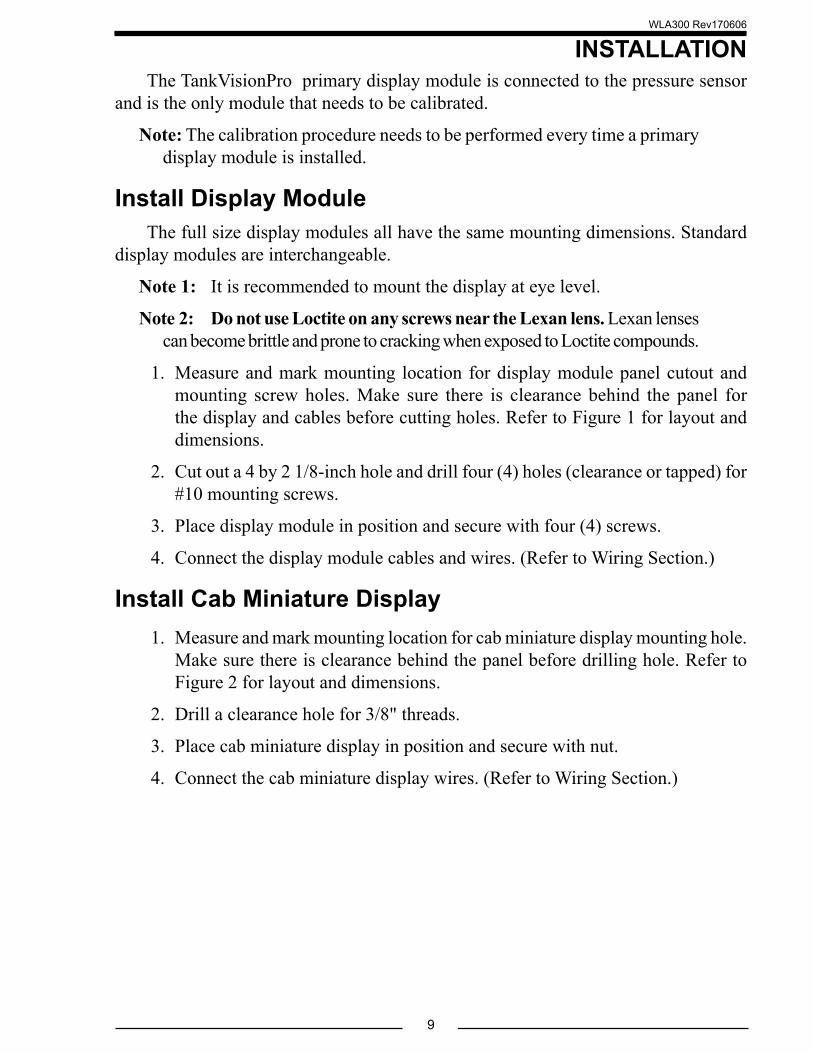
INSTALLATIONThe TankVisionPro primary display module is connected to the pressure sensor
and is the only module that needs to be calibrated.
Note: The calibration procedure needs to be performed every time a primary display module is installed.
Install Display ModuleThe full size display modules all have the same mounting dimensions. Standard
display modules are interchangeable.
Note 1: It is recommended to mount the display at eye level.
Note 2: Do not use Loctite on any screws near the Lexan lens. Lexan lenses can become brittle and prone to cracking when exposed to Loctite compounds.
1. Measure and mark mounting location for display module panel cutout and mounting screw holes. Make sure there is clearance behind the panel for the display and cables before cutting holes. Refer to Figure 1 for layout and dimensions.
2. Cut out a 4 by 2 1/8-inch hole and drill four (4) holes (clearance or tapped) for #10 mounting screws.
3. Place display module in position and secure with four (4) screws.
4. Connect the display module cables and wires. (Refer to Wiring Section.)
Install Cab Miniature Display1. Measure and mark mounting location for cab miniature display mounting hole.
Make sure there is clearance behind the panel before drilling hole. Refer to Figure 2 for layout and dimensions.
2. Drill a clearance hole for 3/8" threads.
3. Place cab miniature display in position and secure with nut.
4. Connect the cab miniature display wires. (Refer to Wiring Section.)
WLA300 Rev170606
10
CL
CLPanel Cutout
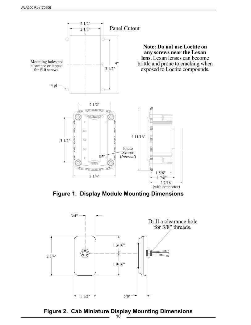
Figure 1. Display Module Mounting Dimensions
5/8"1 1/2"
1 3/16"
1 9/16"
Drill a clearance hole for 3/8" threads.
2 3/4"
3/4"
Figure 2. Cab Miniature Display Mounting Dimensions
Mounting holes are clearance or tapped
for #10 screws.
2 1/2"
2 1/2"
2 7/16"
3 1/2"
3 1/2"
1 5/8"1 7/8"
4 11/16"
3 1/4"
2 1/8"
4"
4 pl
(with connector)
PhotoSensor
(Internal)
Note: Do not use Loctite on any screws near the Lexan
lens. Lexan lenses can become brittle and prone to cracking when
exposed to Loctite compounds.
WLA300 Rev170606
11
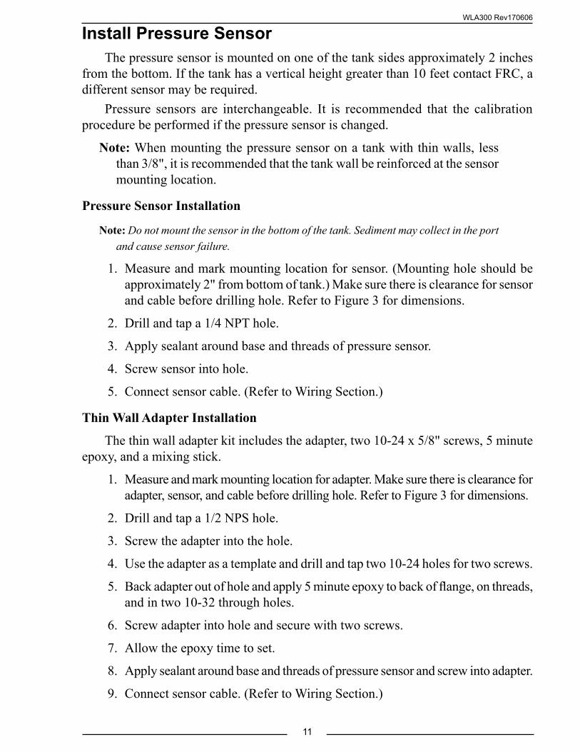
Install Pressure SensorThe pressure sensor is mounted on one of the tank sides approximately 2 inches
from the bottom. If the tank has a vertical height greater than 10 feet contact FRC, a different sensor may be required.
Pressure sensors are interchangeable. It is recommended that the calibration procedure be performed if the pressure sensor is changed.
Note: When mounting the pressure sensor on a tank with thin walls, less than 3/8", it is recommended that the tank wall be reinforced at the sensor mounting location.
Pressure Sensor Installation
Note: Do not mount the sensor in the bottom of the tank. Sediment may collect in the port and cause sensor failure.
1. Measure and mark mounting location for sensor. (Mounting hole should be approximately 2" from bottom of tank.) Make sure there is clearance for sensor and cable before drilling hole. Refer to Figure 3 for dimensions.
2. Drill and tap a 1/4 NPT hole.
3. Apply sealant around base and threads of pressure sensor.
4. Screw sensor into hole.
5. Connect sensor cable. (Refer to Wiring Section.)
Thin Wall Adapter Installation
The thin wall adapter kit includes the adapter, two 10-24 x 5/8" screws, 5 minute epoxy, and a mixing stick.
1. Measure and mark mounting location for adapter. Make sure there is clearance for adapter, sensor, and cable before drilling hole. Refer to Figure 3 for dimensions.
2. Drill and tap a 1/2 NPS hole.
3. Screw the adapter into the hole.
4. Use the adapter as a template and drill and tap two 10-24 holes for two screws.
5. Back adapter out of hole and apply 5 minute epoxy to back of flange, on threads, and in two 10-32 through holes.
6. Screw adapter into hole and secure with two screws.
7. Allow the epoxy time to set.
8. Apply sealant around base and threads of pressure sensor and screw into adapter.
9. Connect sensor cable. (Refer to Wiring Section.)
WLA300 Rev170606
12
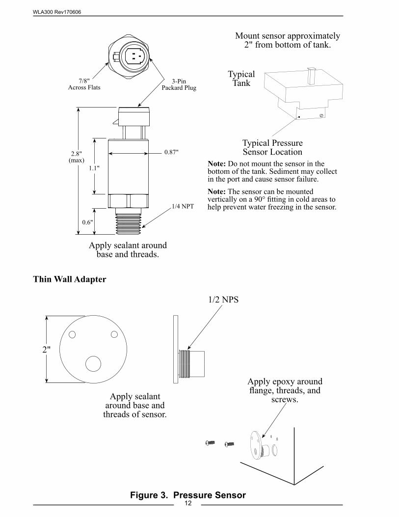
Apply sealant around base and threads.
Thin Wall Adapter
Figure 3. Pressure Sensor
Apply epoxy around flange, threads, and
screws.Apply sealant around base and threads of sensor.
Typical Pressure Sensor Location
Typical Tank
1/2 NPS
2"
Mount sensor approximately 2" from bottom of tank.
Note: The sensor can be mounted vertically on a 90° fitting in cold areas to help prevent water freezing in the sensor.
0.6"
7/8"Across Flats
1/4 NPT
2.8"(max)
1.1"
3-Pin Packard Plug
0.87"
Note: Do not mount the sensor in the bottom of the tank. Sediment may collect in the port and cause sensor failure.
WLA300 Rev170606
13
Install Pressure/Vacuum Foam Tank VentA pressure/vacuum foam tank vent is supplied for use on sealed foam tanks. The
recommended location to mount the vent is in the cover of the foam tank fill tower. If there is no fill tower, mount the vent at the highest point of the tank top so that it is not immersed in foam. For installations where clearance above the fill tower is limited, a 90° mounted vent is available.
Note: The vent can compensate for a maximum foam concentrate flow rate of 60 GPM. If the flow rate of foam concentrate from the tank will exceed 60 GPM, two (2) vents will be required.
Install Top Mounted Tank Vent
The top mounted tank vent is mounted in a vertical position through a 1 1/8-inch hole on the lid of the fill tower and is secured by a hand tightened nut.
Note: The tank vent must be in a vertical position and can not be immersed in foam.
1. Measure and mark mounting location for vent. Make sure there is clearance for the valve before drilling hole. Refer to Figure 4 for dimensions.
2. Drill 1 1/8-inch diameter hole.
3. Insert vent into the hole with the gasket in place.
4. Screw on nut and hand tighten.
Install 90° Mounted Tank Vent
The 90° mounted tank vent is mounted on a vertical side of the fill tower. It must be located as close to the top of the fill tower as possible. The vent is held in place with two (2) 1/4-20 x 3-inch bolts, washers, and locknuts.
Note: The tank vent must be in a vertical position and can not be immersed in foam.
1. Measure and mark mounting location for vent. Make sure there is clearance for the valve before drilling holes. Refer to Figure 4 for dimensions.
2. Drill 3/4-inch diameter hole and two through holes for 1/4-20 bolts.
3. Apply sealant to mounting surfaces and bolt holes.
4. Secure vent in place with two bolts, washers, and locknuts.
WLA300 Rev170606
14
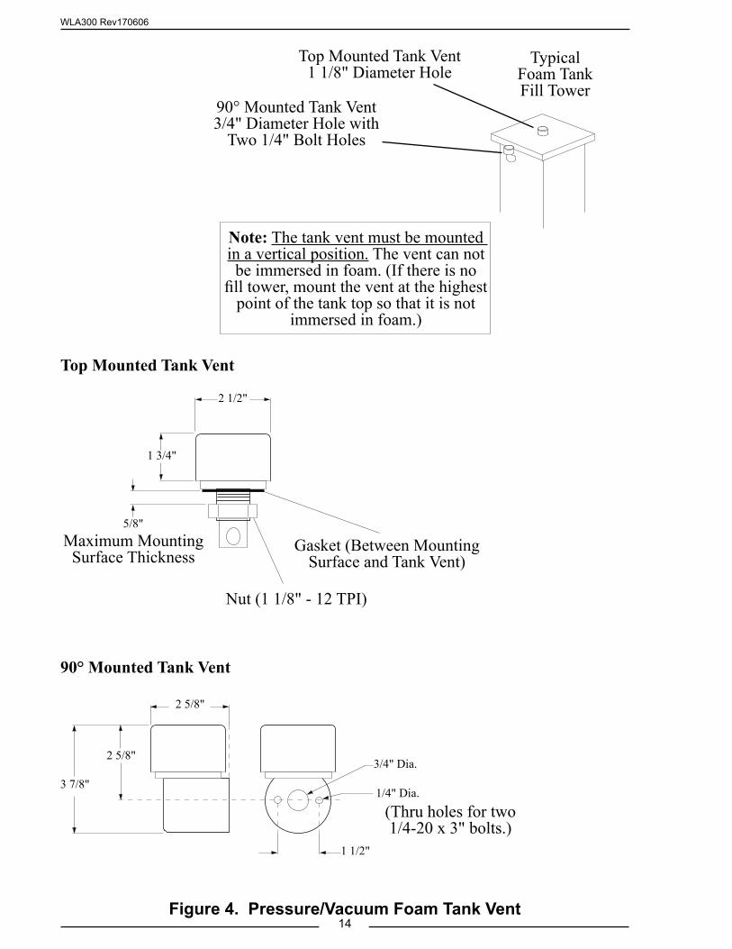
Top Mounted Tank Vent
Gasket (Between Mounting Surface and Tank Vent)
Nut (1 1/8" - 12 TPI)
Maximum Mounting Surface Thickness
1 3/4"
2 1/2"
5/8"
90° Mounted Tank Vent
1/4" Dia.
(Thru holes for two1/4-20 x 3" bolts.)
3/4" Dia.
2 5/8"
Figure 4. Pressure/Vacuum Foam Tank Vent
Note: The tank vent must be mounted in a vertical position. The vent can not be immersed in foam. (If there is no
fill tower, mount the vent at the highest point of the tank top so that it is not
immersed in foam.)
2 5/8"
3 7/8"
1 1/2"
Top Mounted Tank Vent 1 1/8" Diameter Hole
90° Mounted Tank Vent3/4" Diameter Hole with
Two 1/4" Bolt Holes
Typical Foam Tank Fill Tower
WLA300 Rev170606
15
Install MaxVision LED Tank DisplayThe LED display is waterproof to allow for flexibility in the mounting location.
Ensure that the light is mounted with the rear against a flat surface.Mount the display so that the raised MaxVision logo on the lens and the drain notch
on the rubber gasket are at the bottom and is mounted with the rear against a flat surface.The wires can be run through any one of the three holes in the rubber gasket.
Note: Before drilling holes place the light in position to check for fit. Ensure that the display clears all obstructions.
1. Measure and mark the mounting hole locations and through hole for the wiring.
2. Drill the two (2) mounting holes for #10 screws and a wire feed thru hole. Any of the three locations (holes) in the rubber boot can be used for the wires.
Note: Ensure that the terminating resistor is installed on the datalink wires when required.
3. Connect the wiring and secure the light with two (2) screws. (Refer to Wiring Section.)
Terminating Resistor Notes
The datalink requires two terminating resistors.
1. One TankVisionPro with one or two LED displays: Install one resistor close to the primary display; install the other resistor farthest away from the primary display, but closer to the remote display.
2. Two TankVisionPro displays: Install terminating resistor at both ends.
3. If the TankVisionPro is used with a TurboFoam system: Do not install terminating resistor.
Program MaxVision LED Tank DisplayThe MaxVision acts as a remote, and the color pattern will mirror the pattern
chosen for the primary display. (See page 29 for detailed information about synching primary and remote displays.)
Code Entry:
1. Hold a magnet over the calibration point for five seconds. Two middle rows of LEDs come on.
2. Swipe the magnet to select the program to be changed; a row of LEDs come on with each swipe.
Brightness Adjustment:
1. Top 2 rows on - set daytime brightness.
2. Top 3 rows on - set nighttime brightness.
WLA300 Rev170606
16
3. Wait 5 seconds to enter the program.
4. Each swipe changes the LEDs brightness—ten levels that are stepped through and then repeated.
5. Hold the magnet over the calibration point for five seconds to load the new setting. The display blinks three times to confirm setting is loaded.
Programming the MaxVision to Display Foam A, Foam B or Water:
Code Entry:
● Hold a magnet over the calibration point for five seconds. Two middle rows of LEDs come on.
Swipe 4 times to set the display for one of the following options:
● Water (Default option)—displays alternate Blue LEDs
● Foam A—displays alternate Green LEDs
● Foam B—displays alternate Yellow LEDs
1. Wait 5 seconds to enter the program.
2. Each swipe changes the choice from Water, to Foam A, to Foam B—the three options are stepped through and then repeated.
3. Hold the magnet over the calibration point for five seconds to load and save the new setting. The display flashes or blinks three times to confirm setting is saved and updated.
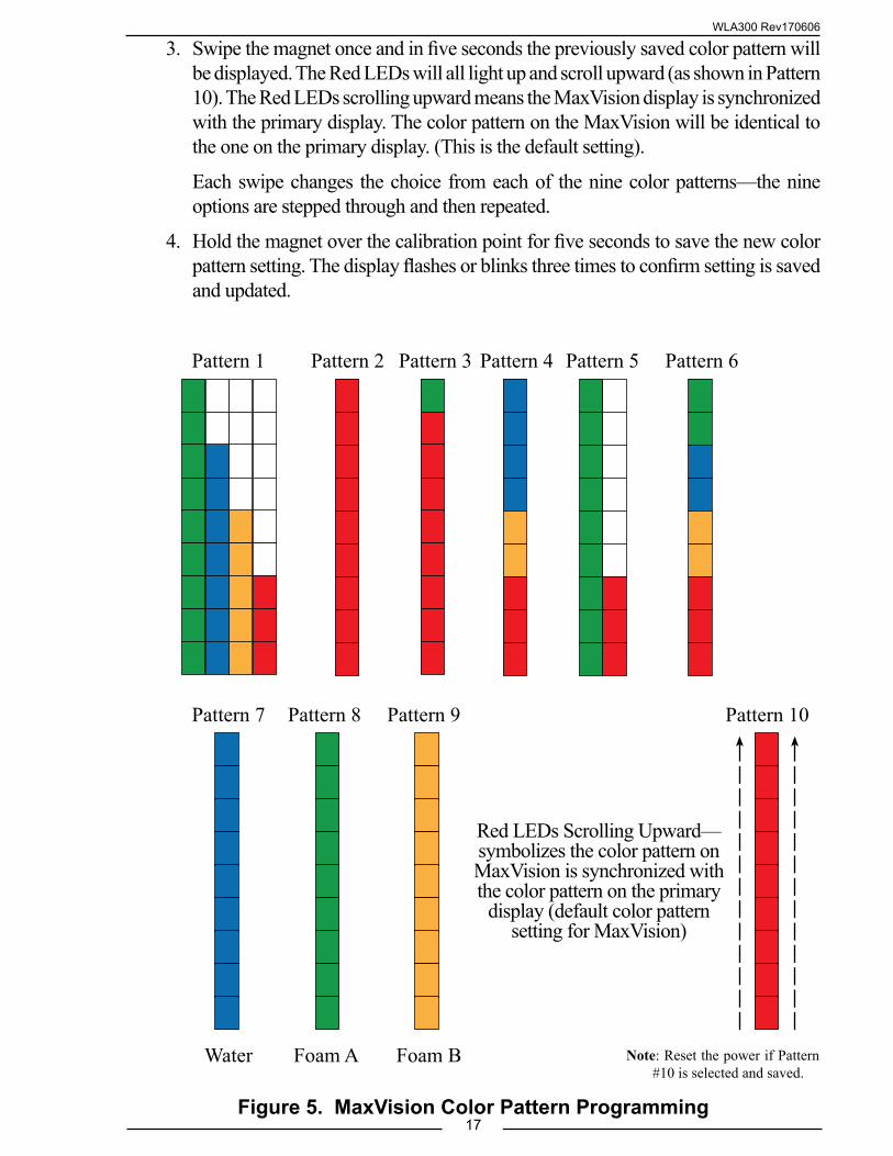
Programming the Color Pattern for the MaxVision:
The default setting for the color pattern is to have this synchronized with the primary display (as described on page 29, Fig. 10). If it is required to have the MaxVision synchronize with the primary display, activate the "Code Entry" (as mentioned on page 15), select Pattern #10, wait for 5 seconds and swipe the magnet once. Save the setting by holding the magnet for 5 seconds at the calibration point.
However, these same six color patterns from Fig. 10 (shown in Fig. 5) can be "locked in" for the MaxVision only, separately from the color pattern shown on the primary display.
Additionally, there are three color patterns to display the status level of either Foam A (all Green LEDs) , Foam B (all Yellow LEDs) or Water (all Blue LEDs). This allows for customizing of up to nine different "locked-in" color patterns on the MaxVision display (separate from the primary display).
Perform the following steps to select the locked in color pattern for the MaxVision:
1. Start the "Code Entry" by holding the magnet the calibration point for five seconds. Two middle rows of LEDs come on.
2. Swipe the magnet to select the program to be changed; a row of LEDs come on with each swipe.
WLA300 Rev170606
17
Pattern 1 Pattern 2 Pattern 3 Pattern 4 Pattern 5 Pattern 6
3. Swipe the magnet once and in five seconds the previously saved color pattern will be displayed. The Red LEDs will all light up and scroll upward (as shown in Pattern 10). The Red LEDs scrolling upward means the MaxVision display is synchronized with the primary display. The color pattern on the MaxVision will be identical to the one on the primary display. (This is the default setting).
Each swipe changes the choice from each of the nine color patterns—the nine options are stepped through and then repeated.
4. Hold the magnet over the calibration point for five seconds to save the new color pattern setting. The display flashes or blinks three times to confirm setting is saved and updated.
Pattern 10Pattern 7
Water
Pattern 8
Foam A
Pattern 9
Foam B
Red LEDs Scrolling Upward—symbolizes the color pattern on MaxVision is synchronized with the color pattern on the primary
display (default color pattern setting for MaxVision)
Figure 5. MaxVision Color Pattern Programming
Note: Reset the power if Pattern #10 is selected and saved.
WLA300 Rev170606
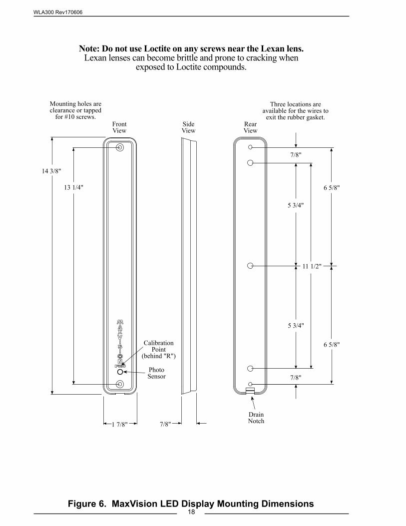
18Figure 6. MaxVision LED Display Mounting Dimensions
14 3/8"
13 1/4"
11 1/2"
5 3/4"
5 3/4"
6 5/8"
6 5/8"
7/8"
7/8"
7/8"1 7/8"
Front View
Side View
Rear View
Three locations are available for the wires to
exit the rubber gasket.
Drain Notch
Mounting holes are clearance or tapped
for #10 screws.
Calibration Point
(behind "R")
Photo Sensor
Note: Do not use Loctite on any screws near the Lexan lens. Lexan lenses can become brittle and prone to cracking when
exposed to Loctite compounds.
WLA300 Rev170606
19
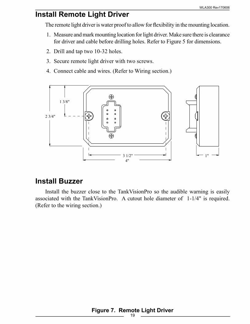
Install Remote Light DriverThe remote light driver is water proof to allow for flexibility in the mounting location.
1. Measure and mark mounting location for light driver. Make sure there is clearance for driver and cable before drilling holes. Refer to Figure 5 for dimensions.
2. Drill and tap two 10-32 holes.
3. Secure remote light driver with two screws.
4. Connect cable and wires. (Refer to Wiring section.)
Figure 7. Remote Light Driver
2 3/4"
1 3/8"
3 1/2"4"
1"
Install BuzzerInstall the buzzer close to the TankVisionPro so the audible warning is easily
associated with the TankVisionPro. A cutout hole diameter of 1-1/4" is required. (Refer to the wiring section.)
WLA300 Rev170606
20
OPERATIONNo operator input is required for the TankVisionPro to be operational. When power
is on, the display is operating. The signal from the pressure sensor is processed and the volume of liquid in the tank shows on the display.
Note: Calibrating the TankVisionPro display to the tank is required before operations. (Refer to Calibration section.)
Primary Display Module
All LEDs are on when the tank is full. Each LED goes off starting at the top and working down as the liquid in the tank decreases.
The bottom 3 LEDs flash when the tank is less than 1/4 full . (For the WLA400 Series, the visual warning indicator signal is synchronized with the flashing LED on the display.)
All LEDs rapidly down-chase when the tank is almost empty.
OptionsProgrammable LED Display
LED Indicator lights can be programmed to be Red for all 9/10 rows, or one of the patterns shown on pages 27-29.
12 Pin Connector with Additional Features:
Visual warning output. (Active ground; Maximum 150mA)
Silence button input for audio warning only. (Active ground)
Separate Valve control output. (Active ground; Maximum 150mA)
Separate ground connection for the level sensor
Remote Display Module
The remote display repeats exactly what is shown on the master display.
Cab Miniature Display
All 5 LEDs is on when the tank is full. The LEDs will show full, 3/4, 1/2, 1/4, and empty tank.
MaxVision LED Display
The LED display repeats exactly what is shown on the master display.
WLA300 Rev170606
21
Remote Light Driver
When power is applied, the remote light driver runs a lamp test function. The lamp test starts at the 1/4 light and cycles each remote light on and off. At the completion of the lamp test, the remote light driver turns on the correct light(s) to show the tank water or foam volume.
All four lights are on when the tank is full. The top light goes off as the tank starts to empty (at 7/8 full the light is off). The three bottom lights are on to show that the tank is between less than full (approx. 7/8 tank) and 1/2 tank. The bottom two lights show 1/2 and 1/4 tank. The bottom light blinks when the tank volume goes less than 1/4 tank.
Buzzer
The buzzer sounds when the tank volume drops to 1/4 tank. (This is programmable. Review the Warning and Control Level Adjustment section on page 28 for detailed information.)
WLA300 Rev170606
22
CALIBRATIONThe TankVisionPro has unique calibration programs that enable it to be used on
tanks of all shapes and sizes.
Note: The standard pressure sensor is limited to a maximum tank height of ten feet.
OverviewMagnet Sensor
The calibration programs are accessed by activating the C 1 and C 2 magnet sensors that are located on the front of the display module. The sensor is activated by placing the north or south pole of a small magnet in close proximity of the sensor. The magnet is then moved about 1-inch away, this will produce an electronic signal that is similar to a button being released. If the LEDs in the display do not change try moving the magnet further away from the sensor.
In these procedures the term ‘swipe’ will mean to move the magnet up to and then away from the magnetic sensor.
Non-Linear Calibration
The first program is a non-linear calibration procedure that can be used for any shape or size tank. This procedure must to be used for irregular shape tanks (e.g.: T-shape, oval, elliptical, tank with through hole, etc.). The program compares the pressure in the tank, as the tank fills at a steady rate, to time. This provides for very accurate displays.
Linear Calibration
The second program is a linear calibration procedure that can only be used when the tank volume is proportional to the height. This would include square or rectangular shape tanks with no irregularities. It is quick way of calibrating a tank but not as accurate as the non-linear procedure. The program compares a full tank to an empty tank, takes the difference and divides it into eight equal volume displays.
Full Tank Correction
This program is for use to fine tune the tank display after a non-linear or linear calibration procedure has been completed. It would only be needed in cases where one type of liquid is used for calibration when a different liquid would normally be in the tank. For example this would allow the basic calibration of a foam tank to be done using water and then the calibration would be fine tuned when the tank is filled with foam concentrate.
WLA300 Rev170606
23
PROGRAMMING CODESCode Entry
1. Swipe the magnet at C1. Each of the bottom row of LEDs turns on one at a time.
2. Swipe the magnet at C2. Each of the top row of LEDs turns on one at a time.
For example:
A. To enter Code 32, swipe the magnet at C1 three times, and then swipe the magnet at C2 twice.
B. If the code is accepted, the display will flash with the corresponding number of top and bottom LEDs as the entered count. For example—three bottom row and two top row LEDs will flash alternately between the top and bottom rows.
3. The process times out after 10 seconds of inactivity, or if no additional codes are entered (except for the non linear calibration).
4. Save the new setting or enable new data entry by holding the magnet at C2 for 5 seconds.
Calibration and Tank Level CorrectionLinear Tank Calibration
1. Start this process with a full tank.
2. Enter Code 44 to activate the Linear tank calibration. (See page 23 for detailed step-by-step instructions.)
Nonlinear Tank Calibration
1. Start this process with an empty tank.
2. Enter Code 33 to activate the Nonlinear tank calibration. (See page 22 for detailed step-by-step instructions.)
Level Correction and Warning
Enter Code 55 to start full level correction. Make sure the tank is almost full, or at greater than 90%.
Enter Code 66 to activate the warning, if the signal is 0.5V higher than the full level.
Note: See page 27 for complete Diagnostics & Warnings information.
WLA300 Rev170606
24
Non-Linear CalibrationThis non-linear calibration procedure can be used for any shape or size tank. The
calibration process requires that the tank be empty at the start of the procedure and then filled at a steady rate of flow.
The term ‘swipe’ means to move the magnet up to and then away from the C 1 and C 2 sensors on front of the display.
Note: To exit the calibration mode without saving any new calibration, reset the power to the display.
1. Empty the tank.
2. Apply power to the display module.
3. Swipe the magnet three times at C 1 and three times at C 2 to enter the calibration mode. Hold the magnet at C 2 for five seconds to activate the calibration.
Result: Top three display LEDs and bottom three LEDs flash on and off.
Note: Once the calibration process is activated the flow rate of liquid into the tank must remain constant for the procedure to be accurate.
4. Fill the tank at a steady rate of flow.
Note: As the tank is filling up, the display will simulate a visual "fill-up" light pattern.
5. When the tank is full stop the flow.
6. Hold the magnet at C 2 for five seconds to set the calibration into memory.
7. After six seconds the calibration process terminates and all the LEDs are on to show that the tank is full.
WLA300 Rev170606
25
Linear CalibrationThis linear calibration procedure can only be used for square or rectangular shape
tanks with no irregularities. The calibration process requires that the tank be full at the start of the procedure.
The term ‘swipe’ means to move the magnet up to and then away from the C 1 or C 2 sensors on front of the display.
Note: To exit the calibration mode without saving any new calibration, reset the power to the display.
1. Fill the tank. (Do not fill up into the fill tower.)
2. Apply power to the display module.
Note: Once the calibration program is activated there is a six second time out. Do not wait more than six seconds to move from step 3 to step 4.
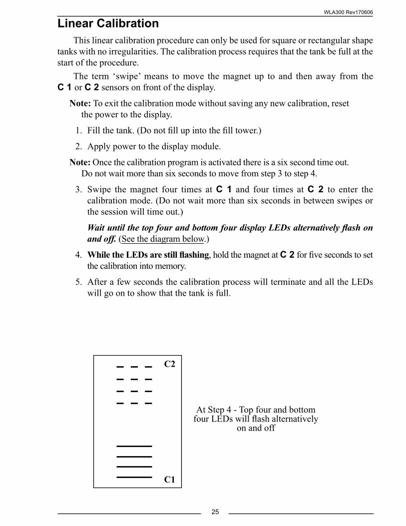
3. Swipe the magnet four times at C 1 and four times at C 2 to enter the calibration mode. (Do not wait more than six seconds in between swipes or the session will time out.)
Wait until the top four and bottom four display LEDs alternatively flash on and off. (See the diagram below.)
4. While the LEDs are still flashing, hold the magnet at C 2 for five seconds to set the calibration into memory.
5. After a few seconds the calibration process will terminate and all the LEDs will go on to show that the tank is full.
C1
C2
At Step 4 - Top four and bottom four LEDs will flash alternatively
on and off
WLA300 Rev170606
26
Full Tank Correction (Code 55)This fine calibration procedure is used to fine tune the tank display after a
non-linear or linear calibration has been completed. The calibration process requires that the tank be full at the start of the procedure and the display shows 75% or more.
The term ‘swipe’ means to move the magnet up to and then away from the C 1 or C 2 sensors on front of the display.
Note: To exit the calibration mode without saving any new calibration, reset the power to the display.
1. Fill the tank. (Do not fill up into the fill tower.)
2. Apply power to the display module.
Note: Once the calibration program is activated there is a six second time out. Do not wait more than six seconds to move from step 3 to step 4.
3. Swipe the magnet five times at C 1 and five times at C 2 to enter the calibration mode.
Result: Top and bottom five display LEDs flash on and off.
4. After three seconds hold the magnet at C 2 for five seconds to set the calibration into memory.
5. After six seconds the calibration process will terminate and all the LEDs will go on to show that the tank is full.
WLA300 Rev170606
27
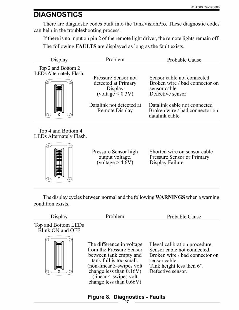
DIAGNOSTICSThere are diagnostic codes built into the TankVisionPro. These diagnostic codes
can help in the troubleshooting process.If there is no input on pin 2 of the remote light driver, the remote lights remain off.The following FAULTS are displayed as long as the fault exists.
Figure 8. Diagnostics - Faults
Top 4 and Bottom 4 LEDs Alternately Flash.
Pressure Sensor high output voltage.
(voltage > 4.6V)
Shorted wire on sensor cablePressure Sensor or Primary Display Failure
Top 2 and Bottom 2 LEDs Alternately Flash.
Pressure Sensor not detected at Primary
Display(voltage < 0.3V)
Sensor cable not connectedBroken wire / bad connector on sensor cableDefective sensor
Datalink not detected at Remote Display
Datalink cable not connectedBroken wire / bad connector on datalink cable
Problem Probable CauseDisplay
The display cycles between normal and the following WARNINGS when a warning condition exists.
Top and Bottom LEDs Blink ON and OFF
The difference in voltage from the Pressure Sensor between tank empty and
tank full is too small.(non-linear 3-swipes volt change less than 0.16V)
(linear 4-swipes volt change less than 0.66V)
Illegal calibration procedure.Sensor cable not connected.Broken wire / bad connector on sensor cable.Tank height less then 6”.Defective sensor.
Problem Probable CauseDisplay
WLA300 Rev170606
28
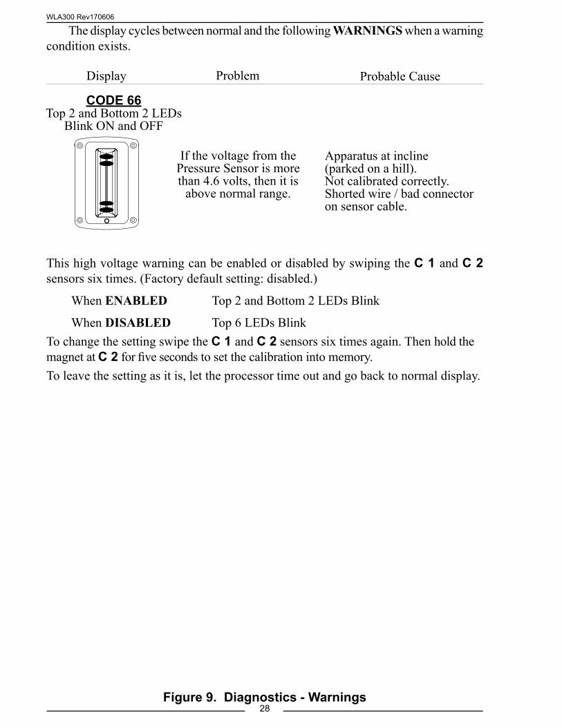
This high voltage warning can be enabled or disabled by swiping the C 1 and C 2 sensors six times. (Factory default setting: disabled.)
When ENABLED Top 2 and Bottom 2 LEDs Blink
When DISABLED Top 6 LEDs BlinkTo change the setting swipe the C 1 and C 2 sensors six times again. Then hold the magnet at C 2 for five seconds to set the calibration into memory. To leave the setting as it is, let the processor time out and go back to normal display.
If the voltage from the Pressure Sensor is more than 4.6 volts, then it is
above normal range.
CODE 66Top 2 and Bottom 2 LEDs
Blink ON and OFF
Apparatus at incline (parked on a hill).Not calibrated correctly.Shorted wire / bad connector on sensor cable.
Figure 9. Diagnostics - Warnings
The display cycles between normal and the following WARNINGS when a warning condition exists.
Problem Probable CauseDisplay
WLA300 Rev170606
29Figure 10. Color Pattern Selection
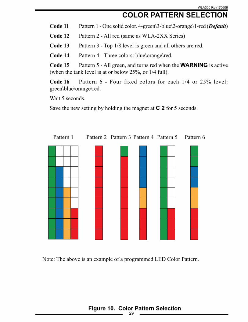
COLOR PATTERN SELECTIONCode 11 Pattern 1 - One solid color. 4-green\3-blue\2-orange\1-red (Default)
Code 12 Pattern 2 - All red (same as WLA-2XX Series)
Code 13 Pattern 3 - Top 1/8 level is green and all others are red.
Code 14 Pattern 4 - Three colors: blue\orange\red.
Code 15 Pattern 5 - All green, and turns red when the WARNING is active (when the tank level is at or below 25%, or 1/4 full).
Code 16 Pattern 6 - Four fixed colors for each 1/4 or 25% level: green\blue\orange\red.
Wait 5 seconds.
Save the new setting by holding the magnet at C 2 for 5 seconds.
Pattern 1 Pattern 2 Pattern 3 Pattern 4 Pattern 5 Pattern 6
Note: The above is an example of a programmed LED Color Pattern.
WLA300 Rev170606
30
Warning and Control Level AdjustmentCode 21 To set the Audio warning level. Default—1/4 (25%)
Code 22 To set the Visual warning level. Default—1/4 (25%)
Code 23 To s e t t h e " Ta n k F u l l " a u d i o s i g n a l l e v e l . Default—disabled.
Code 24 To set the Valve control signal "Low" activation level. Default— 1/2 (50%)
Code 25 To set the Valve control signal "Full" deactivation level. Default —7/8 (95%)
Code 26 To set the level for Audio warning to be turned off (or disabled). Default —1/4 (25%)
Code 27 To set the level for Visual warning to be turned off. Default —1/4 (25%)
Code 28 To set the delay time in seconds before the Audio warning is activated. Default —1 second (NOTE: each LED delays the Audio warning activation by 1 second. This is adjustable from 1 to 7 seconds. )
1. Enable the data entry by holding the magnet at C 2 for 5 seconds. This sets the desired level for either Warnings or Valve Control setting activation.
2. Wait five seconds.
3. Save the new setting by holding the magnet at C 2 for 5 seconds.
Note: If the WL300 is set with code 24 and 25, the buzzer output will work as a valve controller.
Figure 11. Diagnostics - Warnings
WLA300 Rev170606
31
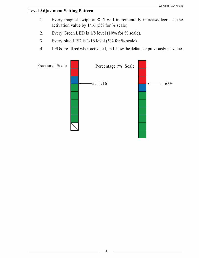
Percentage (%) ScaleFractional Scale
at 11/16 at 65%
Level Adjustment Setting Pattern
1. Every magnet swipe at C 1 will incrementally increase/decrease the activation value by 1/16 (5% for % scale).
2. Every Green LED is 1/8 level (10% for % scale).
3. Every blue LED is 1/16 level (5% for % scale).
4. LEDs are all red when activated, and show the default or previously set value.
WLA300 Rev170606
32
Brightness AdjustmentCode 31 Day time brightness. Default—Brightness Level - 8
Code 32 Night time brightness. Default—Brightness Level - 2
1. Every magnet swipe at C 1 will incrementally increase/decrease the brightness for 10 various levels.
2. Starting from the lowest level, repeat the process from number 1.
3. Enable the data entry by holding the magnet at C 2 for 5 seconds.
4. Adjust the brightness to the desired level.
5. Save the new setting by holding the magnet at C 2 for 5 seconds.
Primary and Remote SynchronizationIf the level pressure sensor is detected, (0.3V or more) the unit will work as a
Primary display. Any remote unit including Water, Foam A, or Foam B, and MaxVision, that is connected via CAN bus will be synchronized with following settings:
• Tank level calibration
• Display Pattern
• Warning and control activation levels
NOTE: Brightness will remain as adjusted locally in the remote display unit.
WLA300 Rev170606
33
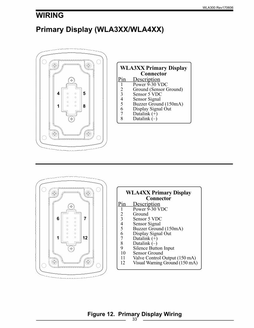
WIRING
Primary Display (WLA3XX/WLA4XX)
1
4 5
8
WLA4XX Primary Display Connector
Pin Description 1 Power 9-30 VDC 2 Ground 3 Sensor 5 VDC 4 Sensor Signal 5 Buzzer Ground (150mA) 6 Display Signal Out 7 Datalink (+) 8 Datalink (–) 9 Silence Button Input 10 Sensor Ground 11 Valve Control Output (150 mA) 12 Visual Warning Ground (150 mA)
WLA3XX Primary Display Connector
Pin Description 1 Power 9-30 VDC 2 Ground (Sensor Ground) 3 Sensor 5 VDC 4 Sensor Signal 5 Buzzer Ground (150mA) 6 Display Signal Out 7 Datalink (+) 8 Datalink (–)
Figure 12. Primary Display Wiring
6
1 12
7
WLA300 Rev170606
34
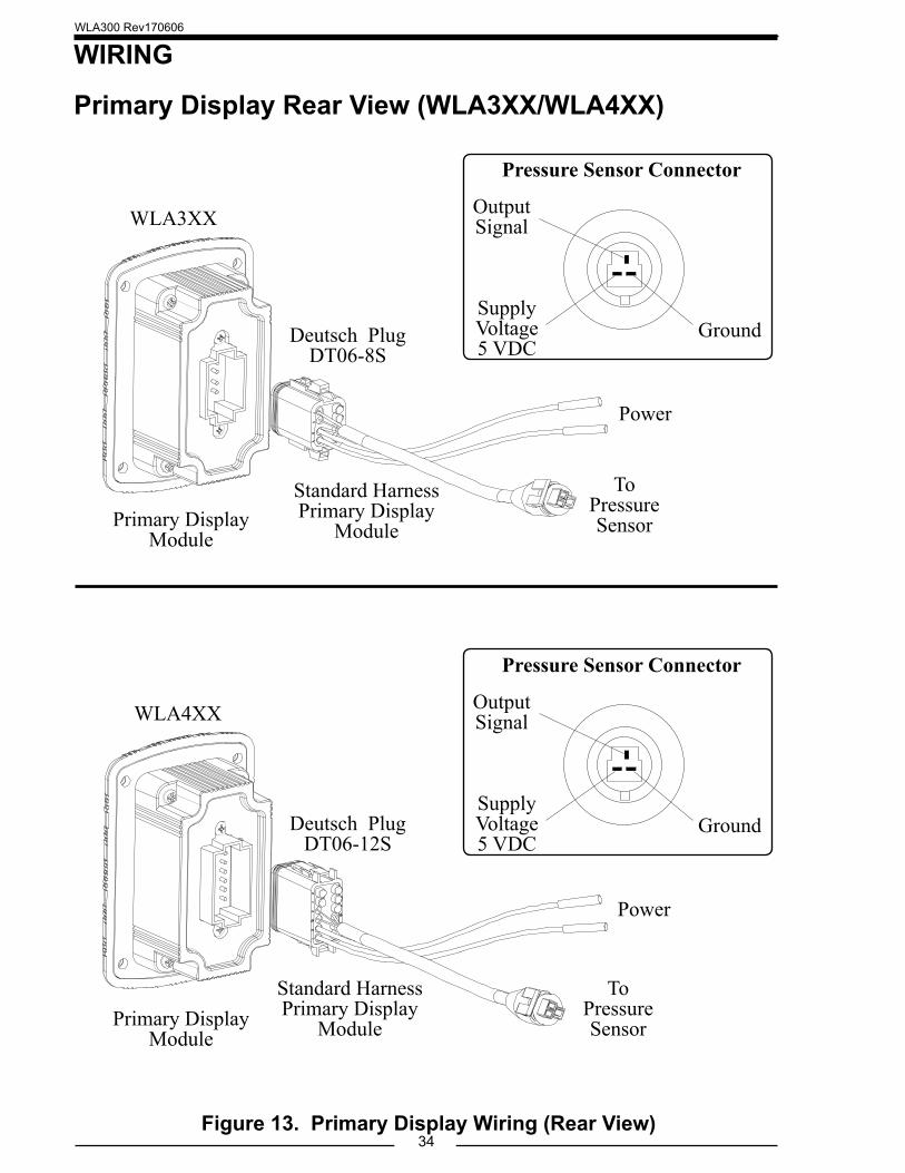
WIRING
Primary Display Rear View (WLA3XX/WLA4XX)
Figure 13. Primary Display Wiring (Rear View)
Standard Harness Primary Display
Module
Standard Harness Primary Display
Module
Deutsch PlugDT06-8S
Deutsch PlugDT06-12S
Primary Display Module
Primary Display Module
ToPressure Sensor
ToPressure Sensor
Power
Power
Pressure Sensor Connector
Supply Voltage 5 VDC
Output Signal
Ground
WLA3XX
WLA4XX
Pressure Sensor Connector
Supply Voltage 5 VDC
Output Signal
Ground
WLA300 Rev170606
35
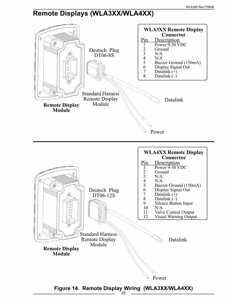
Power
Power
Datalink
Datalink
Remote Displays (WLA3XX/WLA4XX)
Remote Display Module
Remote Display Module
Standard Harness Remote Display
Module
Standard Harness Remote Display
Module
Deutsch PlugDT06-8S
Deutsch PlugDT06-12S
WLA3XX Remote Display Connector
Pin Description 1 Power 9-30 VDC 2 Ground 3 N/A 4 N/A 5 Buzzer Ground (150mA) 6 Display Signal Out 7 Datalink (+) 8 Datalink (–)
WLA4XX Remote Display Connector
Pin Description 1 Power 9-30 VDC 2 Ground 3 N/A 4 N/A 5 Buzzer Ground (150mA) 6 Display Signal Out 7 Datalink (+) 8 Datalink (–) 9 Silence Button Input 10 N/A 11 Valve Control Output 12 Visual Warning Output
Figure 14. Remote Display Wiring (WLA3XX/WLA4XX)
WLA300 Rev170606
36
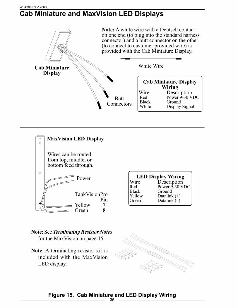
Cab Miniature and MaxVision LED Displays
Note: A white wire with a Deutsch contact on one end (to plug into the standard harness connector) and a butt connector on the other (to connect to customer provided wire) is provided with the Cab Miniature Display.
Butt Connectors
Cab Miniature Display
Cab Miniature Display Wiring
Wire Description Red Power 9-30 VDC Black Ground White Display Signal
Figure 15. Cab Miniature and LED Display Wiring
White Wire
LED Display WiringWire DescriptionRed Power 9-30 VDCBlack GroundYellow Datalink (+)Green Datalink (–)
MaxVision LED Display
Wires can be routed from top, middle, or bottom feed through.
TankVisionProPin
Yellow 7Green 8
Power
Note: A terminating resistor kit is included with the MaxVision LED display.
Note: See Terminating Resistor Notes for the MaxVision on page 15.
WLA300 Rev170606
37
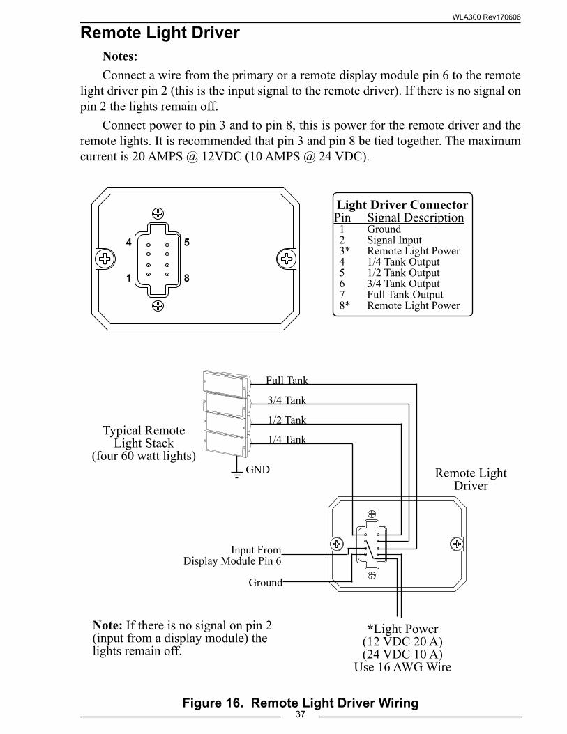
Remote Light DriverNotes:Connect a wire from the primary or a remote display module pin 6 to the remote
light driver pin 2 (this is the input signal to the remote driver). If there is no signal on pin 2 the lights remain off.
Connect power to pin 3 and to pin 8, this is power for the remote driver and the remote lights. It is recommended that pin 3 and pin 8 be tied together. The maximum current is 20 AMPS @ 12VDC (10 AMPS @ 24 VDC).
1
4 5
8
Figure 16. Remote Light Driver Wiring
Light Driver ConnectorPin Signal Description 1 Ground 2 Signal Input 3* Remote Light Power 4 1/4 Tank Output 5 1/2 Tank Output 6 3/4 Tank Output 7 Full Tank Output 8* Remote Light Power
Remote Light Driver
*Light Power(12 VDC 20 A)(24 VDC 10 A)
Use 16 AWG Wire
GND
Full Tank
Typical Remote Light Stack
(four 60 watt lights)
Ground
Input FromDisplay Module Pin 6
1/2 Tank
3/4 Tank
1/4 Tank
Note: If there is no signal on pin 2 (input from a display module) the lights remain off.
WLA300 Rev170606
38
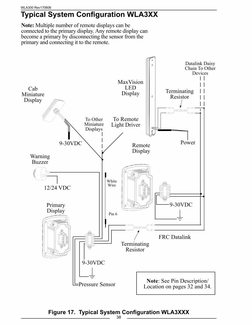
Typical System Configuration WLA3XX
Figure 17. Typical System Configuration WLA3XXX
Primary Display
Pressure Sensor
Remote Display
MaxVisionLED
DisplayCab
Miniature Display
Warning Buzzer
12/24 VDC
9-30VDC
9-30VDC Power
TerminatingResistor
To Remote Light Driver
To Other Miniature Displays
Datalink Daisy Chain To Other
Devices
FRC Datalink
9-30VDC
Note: See Pin Description/Location on pages 32 and 34.
TerminatingResistor
Note: Multiple number of remote displays can be connected to the primary display. Any remote display can become a primary by disconnecting the sensor from the primary and connecting it to the remote.
White Wire
Pin 6
WLA300 Rev170606
39
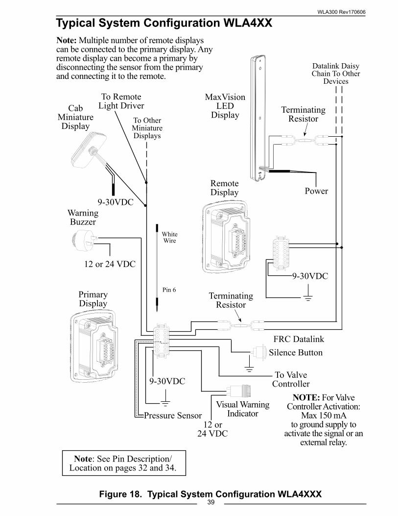
Typical System Configuration WLA4XX
Figure 18. Typical System Configuration WLA4XXX
Note: Multiple number of remote displays can be connected to the primary display. Any remote display can become a primary by disconnecting the sensor from the primary and connecting it to the remote.
Note: See Pin Description/Location on pages 32 and 34.
Primary Display
Pressure Sensor
Remote Display
MaxVisionLED
DisplayCab
Miniature Display
Warning Buzzer
Visual Warning Indicator
Silence Button
12 or 24 VDC9-30VDC
Power
TerminatingResistor
To Remote Light Driver
To Other Miniature Displays
Datalink Daisy Chain To Other
Devices
FRC Datalink
To Valve Controller9-30VDC
9-30VDC
TerminatingResistor
White Wire
Pin 6
12 or 24 VDC
NOTE: For Valve Controller Activation:
Max 150 mA to ground supply to
activate the signal or an external relay.
WLA300 Rev170606
40
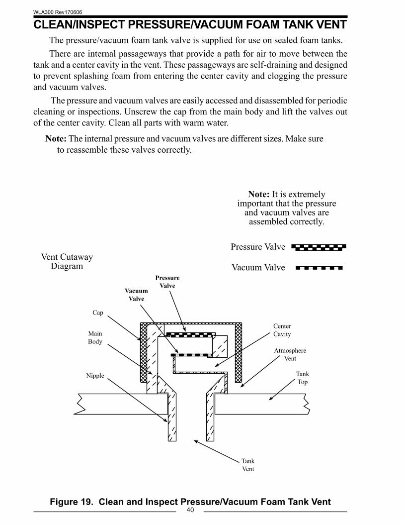
CLEAN/INSPECT PRESSURE/VACUUM FOAM TANK VENTThe pressure/vacuum foam tank valve is supplied for use on sealed foam tanks. There are internal passageways that provide a path for air to move between the
tank and a center cavity in the vent. These passageways are self-draining and designed to prevent splashing foam from entering the center cavity and clogging the pressure and vacuum valves.
The pressure and vacuum valves are easily accessed and disassembled for periodic cleaning or inspections. Unscrew the cap from the main body and lift the valves out of the center cavity. Clean all parts with warm water.
Note: The internal pressure and vacuum valves are different sizes. Make sure to reassemble these valves correctly.
Figure 19. Clean and Inspect Pressure/Vacuum Foam Tank Vent
Pressure Valve
Vacuum Valve
Note: It is extremely important that the pressure
and vacuum valves are assembled correctly.
Pressure Valve
Center Cavity
Vacuum Valve
Tank Vent
Tank Top
Atmosphere Vent
Cap
Main Body
Nipple
Vent Cutaway Diagram
WLA300 Rev170606
41
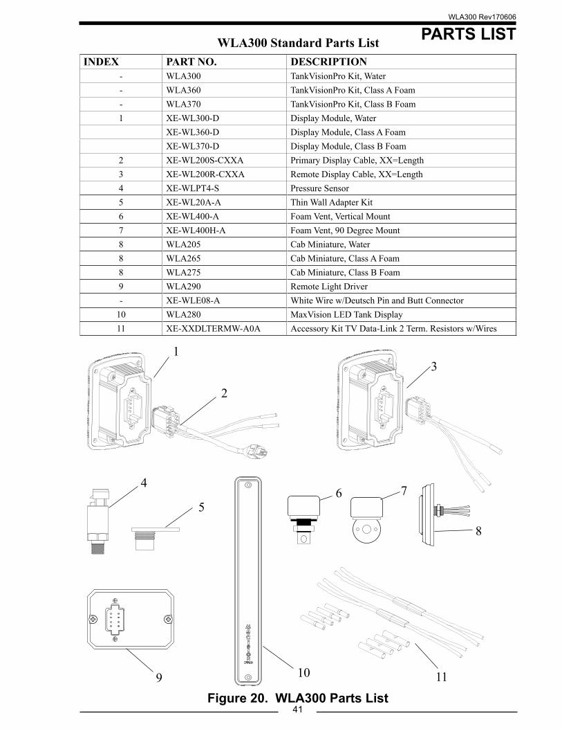
PARTS LIST
Figure 20. WLA300 Parts List9 10 11
3
7
8
5
4
WLA300 Standard Parts ListINDEX PART NO. DESCRIPTION
- WLA300 TankVisionPro Kit, Water- WLA360 TankVisionPro Kit, Class A Foam- WLA370 TankVisionPro Kit, Class B Foam1 XE-WL300-D Display Module, Water
XE-WL360-D Display Module, Class A FoamXE-WL370-D Display Module, Class B Foam
2 XE-WL200S-CXXA Primary Display Cable, XX=Length3 XE-WL200R-CXXA Remote Display Cable, XX=Length4 XE-WLPT4-S Pressure Sensor5 XE-WL20A-A Thin Wall Adapter Kit6 XE-WL400-A Foam Vent, Vertical Mount7 XE-WL400H-A Foam Vent, 90 Degree Mount8 WLA205 Cab Miniature, Water8 WLA265 Cab Miniature, Class A Foam8 WLA275 Cab Miniature, Class B Foam9 WLA290 Remote Light Driver- XE-WLE08-A White Wire w/Deutsch Pin and Butt Connector
10 WLA280 MaxVision LED Tank Display11 XE-XXDLTERMW-A0A Accessory Kit TV Data-Link 2 Term. Resistors w/Wires
6
2
1
WLA300 Rev170606
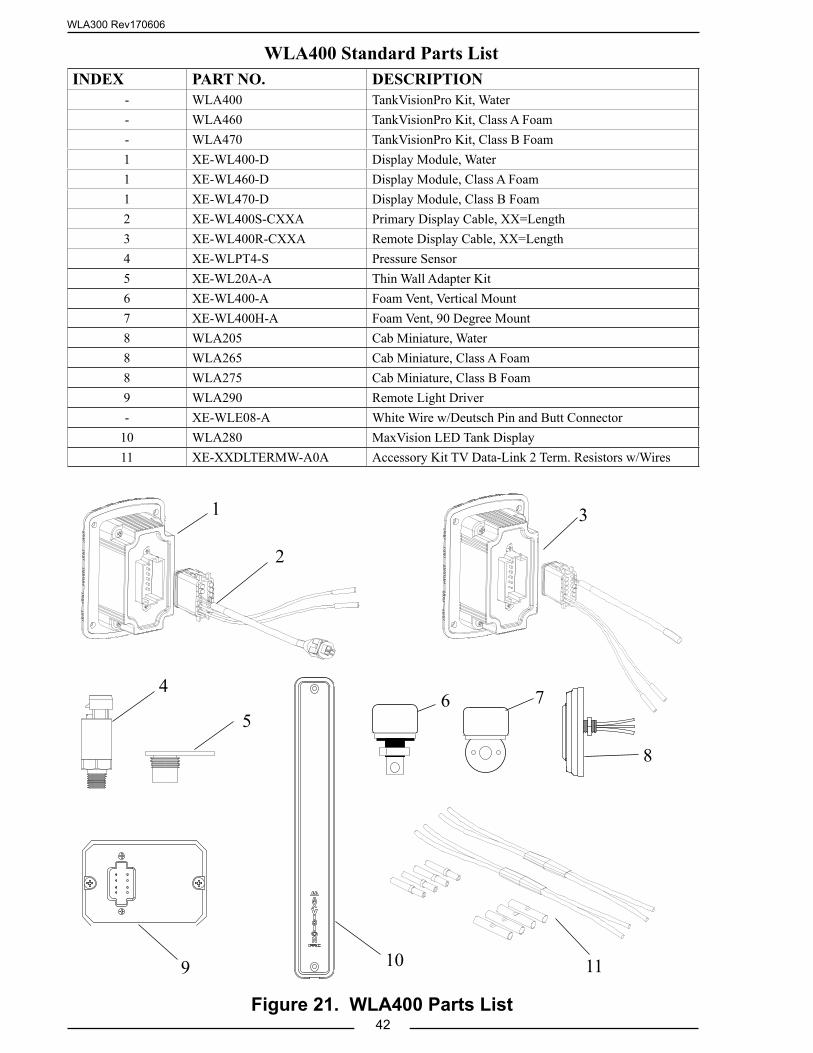
42Figure 21. WLA400 Parts List
WLA400 Standard Parts ListINDEX PART NO. DESCRIPTION
- WLA400 TankVisionPro Kit, Water- WLA460 TankVisionPro Kit, Class A Foam- WLA470 TankVisionPro Kit, Class B Foam1 XE-WL400-D Display Module, Water1 XE-WL460-D Display Module, Class A Foam1 XE-WL470-D Display Module, Class B Foam2 XE-WL400S-CXXA Primary Display Cable, XX=Length3 XE-WL400R-CXXA Remote Display Cable, XX=Length4 XE-WLPT4-S Pressure Sensor5 XE-WL20A-A Thin Wall Adapter Kit6 XE-WL400-A Foam Vent, Vertical Mount7 XE-WL400H-A Foam Vent, 90 Degree Mount8 WLA205 Cab Miniature, Water8 WLA265 Cab Miniature, Class A Foam8 WLA275 Cab Miniature, Class B Foam9 WLA290 Remote Light Driver- XE-WLE08-A White Wire w/Deutsch Pin and Butt Connector
10 WLA280 MaxVision LED Tank Display11 XE-XXDLTERMW-A0A Accessory Kit TV Data-Link 2 Term. Resistors w/Wires
9 10 11
3
7
8
5
4
2
6
1

WLA300 Rev170606
43
NOTES

WLA300 Rev170606
44