Embed Size (px)
Citation preview
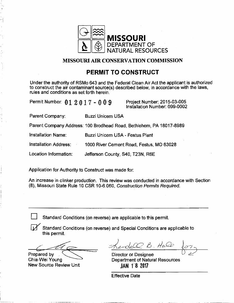
~[§] MISSOURI wl & I DEPARTMENT oF ~ ~ NATURALRESOURCES
MISSOURI AIR CONSERVATION COMMISSION
PERMIT TO CONSTRUCT
Under the authority of RSMo 643 and the Federal Clean Air Act the applicant is authorized to construct the air contaminant source(s) described below, in accordance with the laws, rules and conditions as set forth herein.
Permit Number: 01 2 0 1 7 - 0 0 9 Project Number: 2015-03-005 Installation Number: 099-0002
Parent Company: Buzzi Unicem USA
Parent Company Address: 100 Brodhead Road, Bethlehem, PA 18017-8989
Installation Name:
Installation Address:
Location Information:
Buzzi Unicem USA - Festus Plant
1000 River Cement Road, Festus, MO 63028
Jefferson County, S40, T23N, R6E
Application for Authority to Construct was made for:
An increase in clinker production. This review was conducted in accordance with Section (8), Missouri State Rule 10 CSR 10-6.060, Construction Permits Required.
D Standard Conditions (on reverse) are applicable to this permit.
~ Standard Conditions (on reverse) and Special Conditions are applicable to this permit.
Prepared by . Chia-We:ung New Source Review Unit
Director or Designee Department of Natural Resources
JAN f8 2017
Effective Date
,I
i
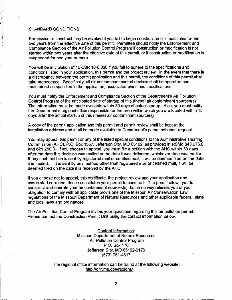
STANDARD CONDITIONS:
Permission to construct may be revoked if you fail to begin construction or modification within two years from the effective date of this permit. Permittee should notify the Enforcement and Compliance Section of the Air Pollution Control Program if construction or modification is not started within two years after the effective date of this permit, or if construction or modification is suspended for one year or more.
You will be in violation of 10 CSR 10-6.060 if you fail to adhere to the specifications and conditions listed in your application, this permit and the project review. In the event that there is a discrepancy between the permit application and this permit, the conditions of this permit shall take precedence. Specifically, all air contaminant control devices shall be operated and maintained as specified in the application, associated plans and specifications.
You must notify the Enforcement and Compliance Section of the Department's Air Pollution Control Program of the anticipated date of startup of this (these) air contaminant sources(s). The information must be made available within 30 days of actual startup. Also, you must notify the Department's regional office responsible for the area within which you are located within 15 days after the actual startup of this (these) air contaminant source(s).
A copy of the permit application and this permit and permit review shall be kept at the installation address and shall be made available to Department's personnel upon request.
You may appeal this permit or any of the listed special conditions to the Administrative Hearing Commission (AHC), P.O. Box 1557, Jefferson City, MO 65102, as provided in RSMo 643.075.6 and 621.250.3. If you choose to appeal, you must file a petition with the AHC within 30 days after the date this decision was mailed or the date it was delivered, whichever date was earlier. If any such petition is sent by registered mail or certified mail, it will be deemed filed on the date it is mailed. If it is sent by any method other than registered mail or certified mail, it will be deemed filed on the date it is received by the AHC.
If you choose not to appeal, this certificate, the project review and your application and associated correspondence constitutes your permit to construct. The permit allows you to construct and operate your air contaminant sources(s}, but in no way relieves you of your obligation to comply with all applicable provisions of the Missouri Air Conservation Law, regulations of the Missouri Department of Natural Resources and other applicable federal, state and local laws and ordinances.
The Air Pollution Control Program invites your questions regarding this air pollution permit. Please contact the Construction Permit Unit using the contact information below.
Contact Information: Missouri Department of Natural Resources
Air Pollution Control Program P.O. Box 176
Jefferson City, MO 65102-0176 (573) 751-4817
The regional office information can be found at the following website: http://dnr.mo.gov/regions/
- 2 -
SPECIAL CONDITIONS:
Project No. 2015-03-005 Permit No.
012017-009
The permittee is authorized to construct and operate subject to the following special conditions:
The special conditions listed in this permit were included based on the authority granted the Missouri Air Pollution Control Program by the Missouri Air Conservation Law (specifically 643.075) and by the Missouri Rules listed in Title 10, Division 10 of the Code of State Regulations (specifically 10 CSR 10-6.060). For specific details regarding conditions, see 10 CSR 10-6.060 paragraph (12)(A)10. "Conditions required by permitting authority." Special Conditions 8.B. and 8.C. taken verbatim from Permit No. 122005-005 and 122005-005A.
Buzzi Unicem USA - Festus Plant Jefferson County, S40, T23N, R6E
1. Superseding Condition A. The conditions of this permit supersede special conditions found in the
following construction permits issued by the Air Pollution Control Program. 1) Special Condition No. 2 in Permit 102014-001. 2) All special conditions in Permit 052012-012. 3) All special conditions in Permit 012010-010. 4) All special conditions in Permit 122005-005A. 5) All special conditions in Permit 122005-005.
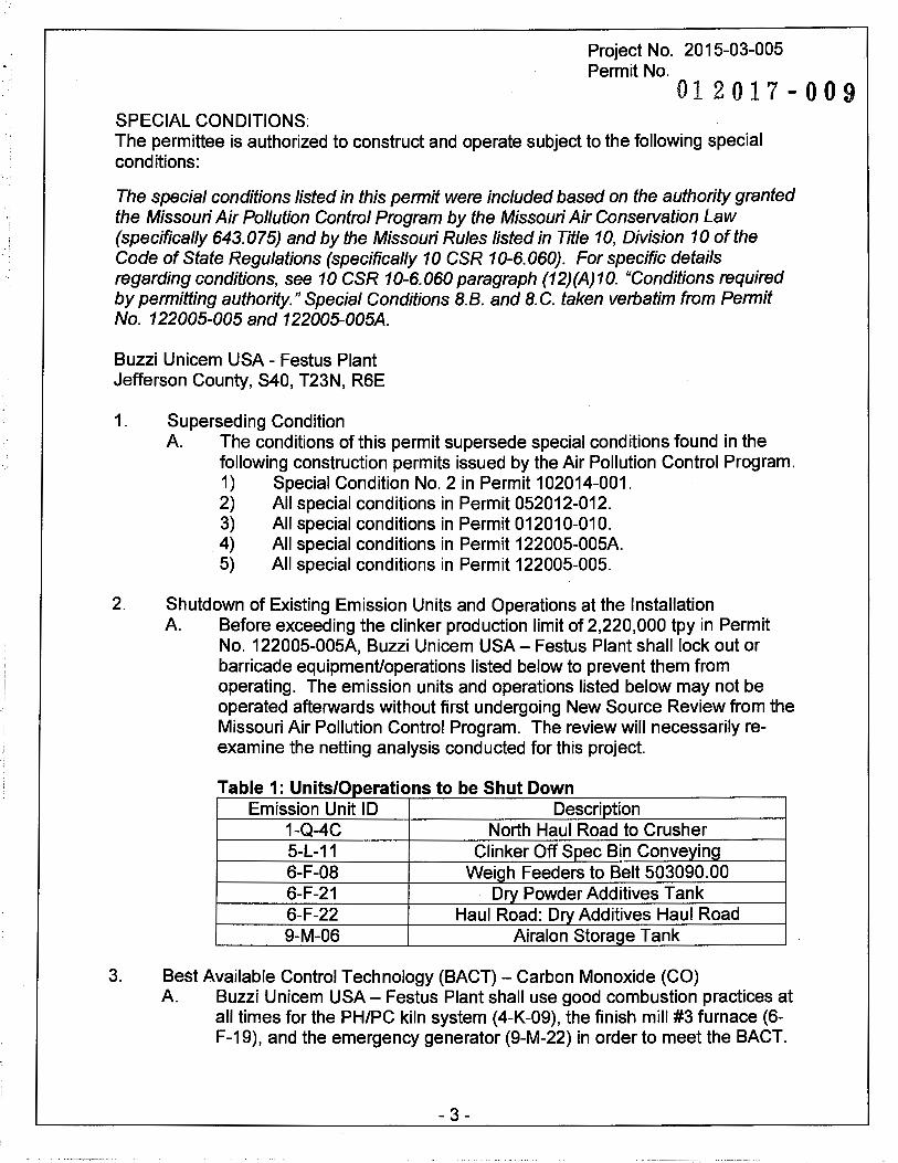
2. Shutdown of Existing Emission Units and Operations at the Installation A. Before exceeding the clinker production limit of 2,220,000 tpy in Permit
No. 122005-005A, Buzzi Unicem USA - Festus Plant shall lock out or barricade equipment/operations listed below to prevent them from operating. The emission units and operations listed below may not be operated afterwards without first undergoing New Source Review from the Missouri Air Pollution Control Program. The review will necessarily reexamine the netting analysis conducted for this project.
T bl 1 U 'ts/0 f t b Sh t D a e . m 1pera ions 0 e u own . Emission Unit ID Description
1-Q-4C North Haul Road to Crusher 5-L-11 Clinker Off Spec Bin Conveying 6-F-08 Weigh Feeders to Belt 503090.00 6-F-21 Dry Powder Additives Tank 6-F-22 Haul Road: Dry Additives Haul Road 9-M-06 Airalon Storage Tank
3. Best Available Control Technology (BACT) - Carbon Monoxide (CO) A. Buzzi Unicem USA- Festus Plant shall use good combustion practices at
all times for the PH/PC kiln system (4-K-09), the finish mill #3 furnace (6-F-19), and the emergency generator (9-M-22) in order to meet the BACT.
- 3 -
'I I
Project No. 2015-03-005
Permit No. 01 2 0 1 7 - 0 0 9
SPECIAL CONDITIONS: The permittee is authorized to construct and operate subject to the following special conditions:
8. The emergency generator (9-M-22) shall also be limited to 500 hours of operation per consecutive twelve month period.
C. Buzzi Unicem USA - Festus Plant shall not emit more than 2.00 pounds of CO per ton of clinker produced from the PH/PC kiln system (4-K-09) based on a 30-day rolling average.
D. Buzzi Unicem USA - Festus Plant shall not emit more than 1,200 pounds of CO per hour of operation from the PH/PC system (4-K-09) based on a 1-hour average.
E. Buzzi Unicem USA - Festus Plant shall not emit more than 2.88 pounds of CO per hour of operation from the finish mill #3 furnace (6-F-19).
F. Buzzi Unicem USA-Festus plant shall perform stack testing to ensure compliance with the CO limit for the finish mill #3 furnace (6-F-19) in Special Conditions 3.E. The tests shall be performed in accordance with Special Condition 7.
G. Buzzi Unicem USA - Festus Plant shall show compliance with the CO limits in Special Condition 3.C. and 3.D. by installing and maintaining CEMs as specified in Special Condition 8.
H. Buzzi Unicem USA- Festus Plant shall not emit more than 0.48 g/hp-hr of CO from the emergency generator (9-M-22). Compliance with this limit shall be through keeping a copy of the manufacturer's emissions guarantee onsite.
I. Buzzi Unicem USA - Festus Plant shall develop an operating and maintenance manual for the finish mill #3 furnace (6-F-19) based on manufacturer's specifications and recommendations for burner operation to ensure that good combustion practice of natural gas occurs as a routine operating practice. This manual shall be finalized within 30 days after exceeding the 2,220,000 tpy clinker limit in Permit No. 122005-005A. 1) System operators shall be provided training on those procedures
prior to operation of the furnace. 2) A written record shall be maintained detailing the names of
employees, date of initial training, and dates of subsequent review of the good combustion practice procedure. The written record shall be updated as necessary to reflect changes in employees.
3) Buzzi Unicem USA - Festus Plant shall make the manual available to any Missouri Department of Natural Resources' personnel upon request.
-4-

Project No. 2015-03-005
Permit No. 01 2 0 1 7 - 0 0 9
SPECIAL CONDITIONS: The permittee is authorized to construct and operate subject to the following special conditions:
4. BACT -Greenhouse Gas Carbon Dioxide Equivalent (GHG-C02e) A Buzzi Unicem USA - Festus Plant shall control GHG-C02e emissions
from the PH/PC Kiln (4-K-09) using the following methods. 1) Use of a five-stage PH/PC kiln system. 2) Use of natural gas as alternative fuel during periods of start-up and
shut-down of the PH/PC kiln system. 3) Vent the clinker cooler exhaust air to the solid fuel mill to dry the
solid fuel and eliminate the need for a thermal dryer in the solid fuel mill.
4) Use of refractory material to line and insulate the PH/PC Kiln. 5) Use of a kiln seal management program to reduce heat loss due to
air filtration.
B. Buzzi Unicem USA - Festus Plant shall control GHG-C02e emissions from Finish Mill #3 Furnace (6-F-19) by using only natural gas as fuel.
C. Buzzi Unicem USA - Festus Plant shall not emit more than 0.95 tons of C02e per ton of clinker from the PH/PC Kiln (4-K-09) based on a 12-month rolling average. At the beginning of each month, Buzzi Unicem USA -Festus Plant shall calculate the monthly average emissions of the previous month and use that month's average with the eleven (11) · preceding months' averages to calculate the 12-month rolling average of the previous 12 months.
D. Buzzi Unicem USA- Festus Plant shall not emit more than 18,057.0 tons of C02e per year from the finish mill #3 furnace (6-F-19) based on a 12-month rolling total. At the beginning of each month, Buzzi Unicem USA -Festus Plant shall calculate both the monthly emissions of the previous month and use that data to calculate the 12-month rolling total of the previous 12 months.
E. Buzzi Unicem USA - Festus Plant shall not emit more than 241.0 tons of C02e per year from the emergency generator (9-M-22) based on a 12-month rolling total. At the beginning of each month, Buzzi Unicem USA -Festus Plant shall calculate both the monthly emissions of the previous month and use that data to calculate the 12-month rolling total of the previous 12 months.
F. Buzzi Unicem USA- Festus Plant shall perform CO2 stack testing on the finish mill #3 furnace (6-F-19), in accordance with Special Condition No. 7 to aid in the demonstration of compliance with Special Condition 4.D. The results of the CO2 stack tests shall be used to calculate the 12-month rolling total of CO2 emissions while 40 CFR 98, subparts A and C shall be used to calculate the 12-month rolling total of other GHG emissions
- 5 -
Project No. 2015-03-005
Permit No. 01 2 0 1 7 - 0 0 9
SPECIAL CONDITIONS: The permittee is authorized to construct and operate subject to the following special conditions:
needed in the demonstration of compliance with Special Condition 4.0. Buzzi Unicem USA - Festus Plant shall develop its own forms for tracking purposes.
G. Buzzi Unicem USA - Festus Plant shall demonstrate compliance with the C02e emissions limit in Special Condition 4.C. for the PH/PC kiln (4-K-09) by installing CO2 CEMS, as specified in Special Condition 8, for determining CO2 emissions and calculating all other applicable GHG emissions (i.e. CH4, N20) per 40 CFR 98, Subparts A and C.
H. Buzzi Unicem USA- Festus Plant shall use 40 CFR 98, Subparts A and C to calculate the 12-month rolling total of GHG emissions from the emergency generator (9-M-22) to demonstrate compliance with Special Condition 4.E. Buzzi Unicem USA - Festus Plant shall develop its own forms for tracking purposes.
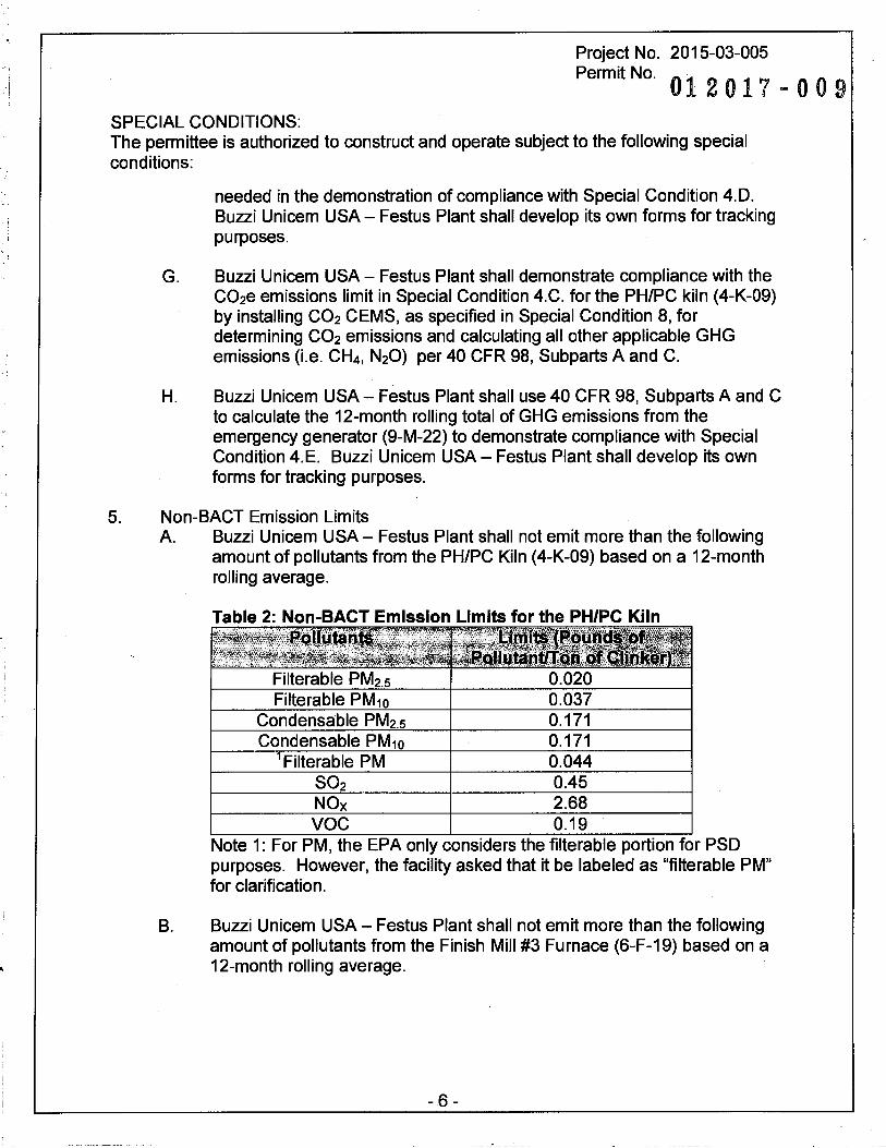
5. Non-BACT Emission Limits A. Buzzi Unicem USA- Festus Plant shall not emit more than the following
amount of pollutants from the PH/PC Kiln (4-K-09) based on a 12-month rolling average.
B.
Filterable PM2.s 0.020 Filterable PM10 0.037
Condensable PM2.s 0.171 Condensable PM10 0.171
Filterable PM 0.044 0.45
NOx 2.68 voe 0.19
Note 1: For PM, the EPA only considers the filterable portion for PSD purposes. However, the facility asked that it be labeled as "filterable PM" for clarification.
Buzzi Unicem USA - Festus Plant shall not emit more than the following amount of pollutants from the Finish Mill #3 Furnace (6-F-19) based on a 12-month rolling average.
- 6 -
Project No. 2015-03.:005 Permit No.
012017-009 SPECIAL CONDITIONS: The permittee is authorized to construct and operate subject to the following special conditions:
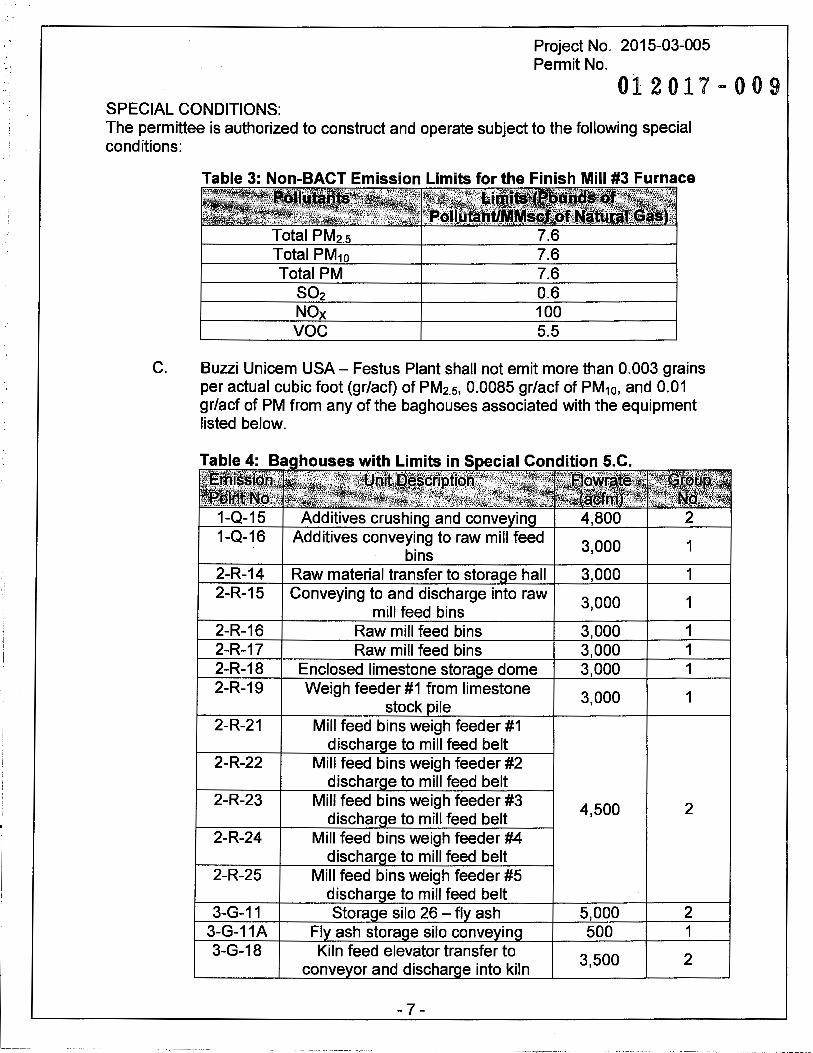
Table 3: Non-BACT Emission Limits for the Finish Mill #3 Furnace
Total PM2.5 7.6 Total PM10 7.6 Total PM 7.6
0.6 NOx 100 voe 5.5
C. Buzzi Unicem USA - Festus Plant shall not emit more than 0.003 grains per actual cubic foot (gr/acf) of PM2.5, 0.0085 gr/acf of PM10, and 0.01 gr/act of PM from any of the bag houses associated with the equipment listed below.
Additives crushin and conve in Additives conveying to raw mill feed
3,000 1 bins
2-R-14 Raw material transfer to stora e hall 3,000 1 2-R-15 Conveying to and discharge into raw
3,000 1 mill feed bins
2-R-16 Raw mill feed bins 3,000 1 2-R-17 Raw mill feed bins 3,000 1 2-R-18 Enclosed limestone stora e dome 3,000 1 2-R-19 Weigh feeder #1 from limestone
3,000 1 stock ile
2-R-21 Mill feed bins weigh feeder #1 dischar e to mill feed belt
2-R-22 Mill feed bins weigh feeder #2 dischar e to mill feed belt
2-R-23 Mill feed bins weigh feeder #3 4,500 2
dischar e to mill feed belt 2-R-24 Mill feed bins weigh feeder #4
dischar e to mill feed belt 2-R-25 Mill feed bins weigh feeder #5
dischar e to mill feed belt 3-G-11 Stora e silo 26 - fl ash 5,000 2
3-G-11A 500 1 3-G-18
3,500 2
- 7 -
---~-------- ----~~---- -- - --~--------
Project No. 2015-03-005
Permit No. 01 2 0 1 7 - 0 0 9
SPECIAL CONDITIONS: The permittee is authorized to construct and operate subject to the following special conditions:
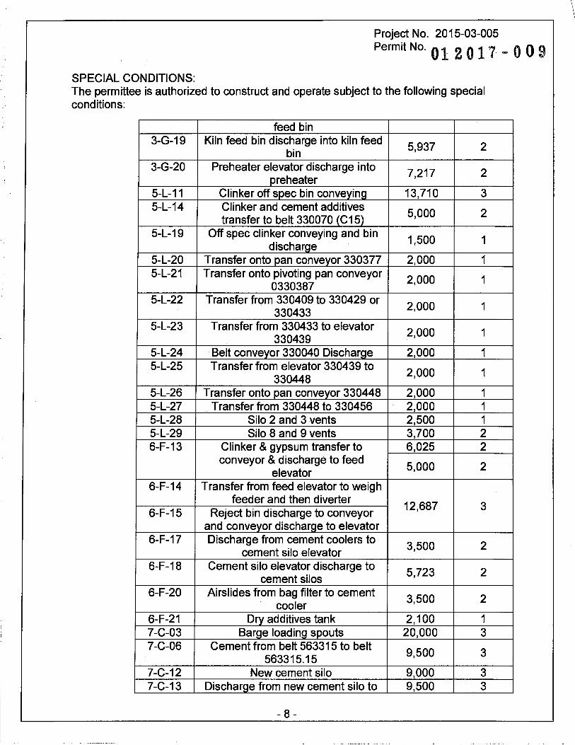
feed bin 3-G-19 Kiln feed bin discharge into kiln feed 5,937 2
bin 3-G-20 Preheater elevator discharge into 7,217 2
preheater 5-L-11 Clinker off spec bin conveying 13,710 3 5-L-14 Clinker and cement additives
5,000 2 transfer to belt 330070 (C15)
5-L-19 Off spec clinker conveying and bin 1,500 1
discharge 5-L-20 Transfer onto pan conveyor 330377 2,000 1 5-L-21 Transfer onto pivoting pan conveyor 2,000 1 0330387 5-L-22 Transfer from 330409 to 330429 or 2,000 1
330433 5-L-23 Transfer from 330433 to elevator 2,000 1 330439 5-L-24 Belt conveyor 330040 Discharge 2,000 1 5-L-25 Transfer from elevator 330439 to
2,000 1 330448
5-L-26 Transfer onto pan conveyor 330448 2,000 1 5-L-27 Transfer from 330448 to 330456 2,000 1 5-L-28 Silo 2 and 3 vents 2,500 1 5-L-29 Silo 8 and 9 vents 3,700 2 6-F-13 Clinker & gypsum transfer to 6,025 2
conveyor & discharge to feed 5,000 2 elevator
6-F-14 Transfer from feed elevator to weigh feeder and then diverter
12,687 3 6-F-15 Reject bin discharge to conveyor
and conveyor discharge to elevator 6-F-17 Discharge from cement coolers to
3,500 2 cement silo elevator
6-F-18 Cement silo elevator discharge to 5,723 2 cement silos
6-F-20 Airslides from bag filter to cement 3,500 2 cooler
6-F-21 Dry additives tank 2,100 1 7-C-03 Barge loading spouts 20,000 3 7-C-06 Cement from belt 563315 to belt
9,500 3 563315.15
7-C-12 New cement silo 9,000 3 7-C-13 Discharge from new cement silo to 9,500 3
- 8 -
\
I
I .. '
Project No. 2015-03-005 Permit No.
012017-009 SPECIAL CONDITIONS: The permittee is authorized to construct and operate subject to the following special conditions:
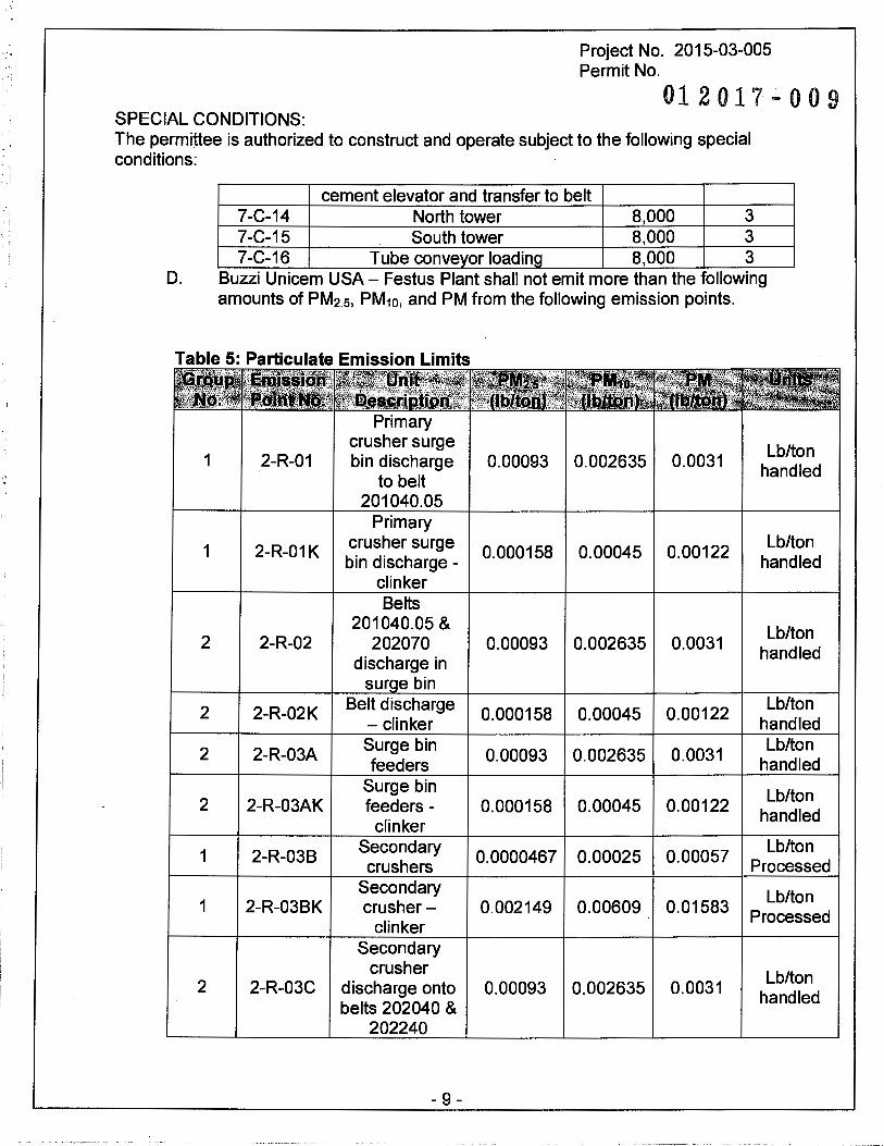
cement elevator and transfer to belt 7-C-14 North tower 8,000 3 7-C-15 South tower 8,000 3 7-C-16 Tube conveyor loading 8,000 3
D. Buzzi Unicem USA - Festus Plant shall not emit more than the following amounts of PM2.5, PM10, and PM from the following emission points.
Table 5: Particulate Emission Limits
Primary crusher surge
Lb/ton 1 2-R-01 bin discharge 0.00093 0.002635 0.0031 handled
to belt 201040.05
Primary
1 2-R-01K crusher surge 0.000158 0.00045 0.00122
Lb/ton bin discharge - handled
clinker Belts
201040.05 & Lb/ton
2 2-R-02 202070 0.00093 0.002635 0.0031 handled
discharge in sur e bin
2 2-R-02K Belt discharge 0.000158 0.00045 0.00122
Lb/ton - clinker handled
2 2-R-03A Surge bin
0.00093 0.002635 0.0031 Lb/ton
feeders handled Surge bin Lb/ton
2 2-R-03AK feeders - 0.000158 0.00045 0.00122 handled
clinker
1 2-R-03B Secondary
0.0000467 0.00025 0.00057 Lb/ton
crushers Processed Secondary Lb/ton
1 2-R-03BK crusher- 0.002149 0.00609 0.01583 Processed
clinker Secondary
crusher Lb/ton 2 2-R-03C discharge onto 0.00093 0.002635 0.0031
handled belts 202040 &
202240
- 9 -

SPECIAL CONDITIONS:
Project No. 2015-03-005 Permit No. O l
·2017-009
The permittee is authorized to construct and operate subject to the following special conditions:
Secondary
2 2-R-03CK crusher 0.000158 0.00045 0.00122
Lb/ton discharge- handled
clinker Transfer belt
Lb/ton 2 2-R-03D 202215 to belt 0.00093 0.002635 0.0031
handled 202040
Transfer from
2 2-R-03E· belt 202260 to
0.00093 0.002635 0.0031 Lb/ton
secondary handled crusher 202230
2 2-R-04 Screen 202250
0.000771 0.00218 0.06562 Lb/ton
and discharge handled
2 2-R-04A Belts 508003 &
0.00093 0.002635 0.0031 Lb/ton
508004 handled Discharge from
2 2-R-13 belts 0.00093 0.002635 0.0031
Lb/ton 202040/202240 handled to belt 220010 Transfer from
Lb/ton NG 2-R-20 Belt 205070 to 3.53x10⁻⁶ 1.0x10⁻⁵ 1.18x10⁻⁵
Belt 205080 handled
Raw Meal Lb/ton
3 3-G-10 blending and 0.00093 0.00264 0.0031 stored
storage Discharge from
4.02x10⁻⁶ Lb/ton NG 3-G-12 mill feed belt to 1.1 x10⁻⁵ 1.34x10⁻⁵
processed inline raw mill
Raw mill Lb/ton
NG 3-G-15 cyclones 3.43x10⁻⁶ 9.71x10⁻⁶ 1.14x10⁻⁵
processed conveying
2 3-G-17 Conveying to
0.00093 0.002635 0.0031 Lb/ton
blending silos processed Discharge from
8.86x10⁻⁵ Lb/ton NG 4-K-10 clinker cooler 2.51x10⁻⁴ 2.95x10_4
clinker to conveyor
Belt 330070 to Lb/ton
2 5-L-15 belt conv & trip 0.00072 0.00204 0.0024 clinker
330090
2 5-L-15A Belt 202040
0.00072 0.00204 0.0024 Lb/ton
transfer clinker
2 5-L-16 Tripper
0.00072 0.00204 0.0024 Lb/ton
discharge into clinker
- 10 -
Project No. 2015-03-005 Permit No.
012017-009 SPECIAL CONDITIONS: The permittee is authorized to construct and operate subject to the following special conditions:
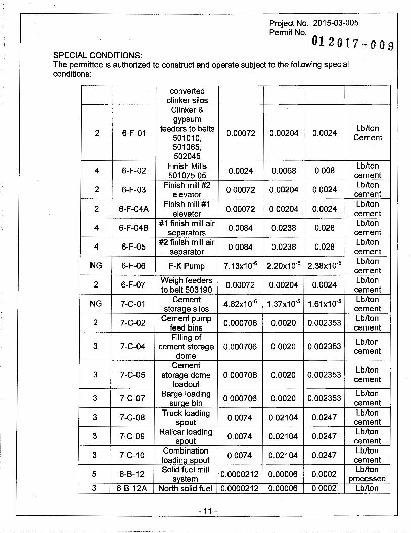
converted clinker silos
Clinker & gypsum
2 6-F-01 feeders to belts
0.00072 0.00204 0.0024 501010, 501065, 502045
4 6-F-02 Finish Mills
0.0024 0.0068 0.008 501075.05
2 6-F-03 Finish mill #2
0.00072 0.00204 0.0024 elevator
2 6-F-04A Finish mill #1
0.00072 0.00204 0.0024 elevator
4 6-F-048 #1 finish mill air
0.0084 0.0238 0.028 separators
4 6-F-05 #2 finish mill air
0.0084 0.0238 0.028 -- - -- separator
NG 6-F-06 F-K Pump 7.13x10⁻⁶ 2.2ox10·5 2.38x10·5
2 6-F-07 Weigh feeders
0.00072 0.00204 0.0024 to belt 503190
NG 7-C-01 Cement 4.82x10⁻⁶ 1.37x10·5 1.61x10"5
storaoe silos
2 7-C-02 Cement pump
0.000706 0.0020 0.002353 feed bins Filling of
3 7-C-04 cement storage 0.000706 0.0020 0.002353 dome
Cement 3 7-C-05 storage dome 0.000706 0.0020 0.002353
loadout
3 7-C-07 Barge loading
0.000706 0.0020 0.002353 suroe bin
3 7-C-08 Truck loading
0.0074 0.02104 0.0247 spout
3 7-C-09 Railcar loading
0.0074 0.02104 0.0247 spout
3 7-C-10 Combination 0.0074 0.02104 0.0247
loadino spout
5 8-8-12 Solid fuel mill
·0.0000212 0.00006 0.0002 system
3 8-B-12A North solid fuel 0.0000212 0.00006 0.0002
- 11 -
Lb/ton Cement
Lb/ton cement Lb/ton
cement Lb/ton
cement Lb/ton
cement Lb/ton
cement Lb/ton
cement Lb/ton
cement Lb/ton
cement Lb/ton
cement
Lb/ton cement
Lb/ton cement
Lb/ton cement Lb/ton
cement Lb/ton
cement Lb/ton
cement Lb/ton
processed Lb/ton
Project No. 2015-03-005 Permit No. O 1 2 O 1 7 - 0 0 9
SPECIAL CONDITIONS: The permittee is authorized to construct and operate subject to the following special conditions:
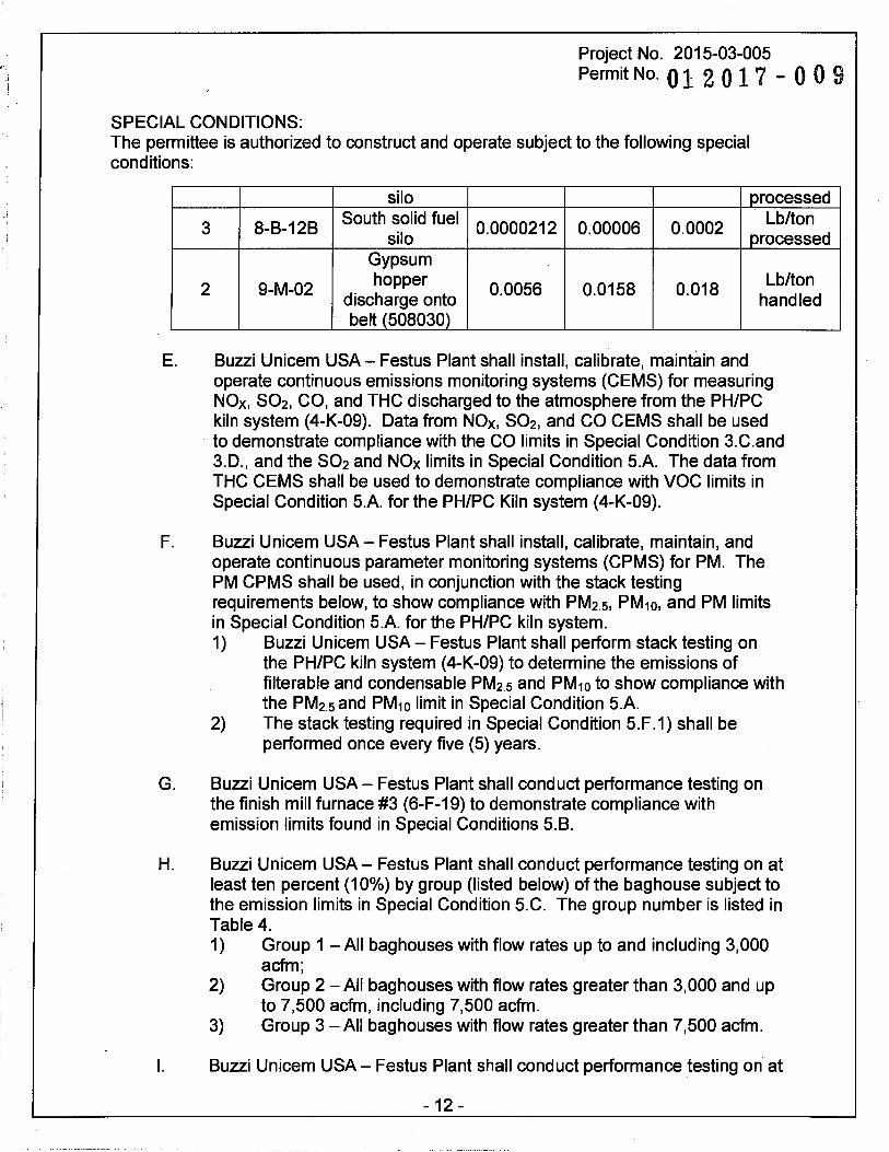
silo processed
3 8-8-128 South solid fuel
0.0000212 0.00006 0.0002 Lb/ton
silo processed Gypsum
2 9-M-02 hopper
0.0056 0.0158 0.018 Lb/ton
discharge onto handled belt {508030)
E. Buzzi Unicem USA- Festus Plant shall install, calibrate, maintain and operate continuous emissions monitoring systems (CEMS) for measuring NOx, S02, CO, and THC discharged to the atmosphere from the PH/PC kiln system (4-K-09). Data from NOx, S02, and CO CEMS shall be used to demonstrate compliance with the CO limits in Special Condition 3.C.and 3.D., and the S02 and NOx limits in Special Condition 5.A. The data from THC CEMS shall be used to demonstrate compliance with voe limits in Special Condition 5.A. for the PH/PC Kiln system (4-K-09).
F. Buzzi Unicem USA- Festus Plant shall install, calibrate, maintain, and operate continuous parameter monitoring systems (CPMS) for PM. The PM CPMS shall be used, in conjunction with the stack testing requirements below, to show compliance with PM2.5, PM10, and PM limits in Special Condition 5.A. for the PH/PC kiln system. 1) Buzzi Unicem USA - Festus Plant shall perform stack testing on
the PH/PC kiln system (4-K-09) to determine the emissions of filterable and condensable PM2.5 and PM10 to show compliance with the PM2.s and PM10 limit in Special Condition 5.A.
2) The stack testing required in Special Condition 5.F.1) shall be performed once every five (5) years.
G. Buzzi Unicem USA - Festus Plant shall conduct performance testing on the finish mill furnace #3 (6-F-19) to demonstrate compliance with emission limits found in Special Conditions 5.8.
H. Buzzi Unicem USA- Festus Plant shall conduct performance testing on at least ten percent (10%) by group (listed below) of the bag house subject to the emission limits in Special Condition 5.C. The group number is listed in Table 4. 1) Group 1 -All baghouses with flow rates up to and including 3,000
acfm; 2) Group 2 -All baghouses with flow rates greater than 3,000 and up
to 7,500 acfm, including 7,500 acfm. 3) Group 3 -All baghouses with flow rates greater than 7,500 acfm.
I. Buzzi Unicem USA - Festus Plant shall conduct performance testing on at
- 12 -
SPECIAL CONDITIONS:
Project No. 2015-03-005 Permit No.
012017-009
The permittee is authorized to construct and operate subject to the following special conditions:
least ten percent (10%) by group of the bag house subject to the emission limits in Special Condition 5.D. The groups are listed in the first column of Table 5. Emission points labeled NG (for "No Grouping") do not need to be tested. ------------ - - ----
J. In lieu of stack testing required in Special Condition 5.H. and 5.1., Buzzi Unicem USA - Festus Plant may provide previous stack testing performed under Permit No. 012005-005 and 012005-005A to demonstrate compliance with the emission limits in Special Condition 5. C. and 5. D. All stack testing data must be submitted to the Air Pollution Control Program.
K. The performance testing required in Special Condition 5.F., 5.G., 5.H., and 5.1. shall be conducted in accordance with the procedures outlined below in Special Condition 7.
L. If the performance testing required by Special Conditions 5.G., 5.H., and 5.1., of this permit indicates that the emission rates listed in Special Conditions 5.8., 5.C., and 5.D. are being exceeded, Buzzi Unicem USAFestus plant shall do the following. 1) Determine whether any exceedance is due to malfunction. 2) If the exceedance is due to a malfunction, Buzzi Unicem USA
Festus Plant shall correct any malfunctions discovered and retest the exceeding unit(s) within 60 days of the initial test results.
3) For each baghouse that exceeds the limits outlined in Special Conditions 5.C. and 5.D that is not due to a malfunction, performance testing on an additional ten percent (10%) of the baghouses subject to the emission limits stated in Special Condition 5.C. and 5.D. will be required.
4) These new performance testing required in Special Condition 5.L.2) and 5.L. 3) shall be done in accordance with the procedures outlined in Special Condition 7.
5) These performance tests shall be conducted within 60 days of the initial test results written report submission to the Director.
M. If any new tests from Special Condition 5.L. shows another exceedance, Buzzi Unicem USA- Festus Plant must evaluate what effects these higher emission rates would have had on the permit applicability of this project. Buzzi Unicem USA - Festus Plant shall use the largest outlet grain loading determined during testing and apply that rate to each of the untested baghouses associated with the equipment listed in Special Condition 10, with the exception of the PH/PC kiln system (4-K-09) and Finish Mill #3 (6-F-16). Buzzi Unicem USA- Festus Plant shall submit the results of any such evaluation in a timely manner to the Air Pollution Control Program.
- 13 -

Project No. 2015-03-005
Permit No.01 2 0 1 7 - 0 0 9
SPECIAL CONDITIONS: The permittee is authorized to construct and operate subject to the following special conditions:
6. Baghouse Upgrade A. Buzzi Unicem USA - Festus Plant shall upgrade the following baghouses
by installing a new Pulse-Jet cleaning technology so that the overall control efficiency of the system is no less than 99.0%. The overall control efficiency shall take into account both capture and control efficiencies.
7-C-05 Cement Storage Dome Loadout: Feeder-Belt 563315
7-C-08 7-C-09 7-C-10
B. Buzzi Unicem USA- Festus Plant shall conduct performance testing, in accordance with Special Condition 7, to show compliance with Special Condition 6.A.
C. The performance test required in Special Condition 6.8. shall test for both the capture and device control efficiency.
7. Performance Testing A. A completed proposed test plan (form enclosed) must be submitted to the
Air Pollution Control Program at least 30 days prior to the proposed test date of any such performance tests so that a pretest meeting may be arranged, if necessary, and to assure that the test date is acceptable for an observer to be present. The proposed test plan must include specification of test methods to be used and be approved by the Director prior to conducting the above required emissions testing.
B. Within 180 days after the installation exceeds the 2,220,000 tpy of clinker production limit in Permit No. 122005-005A, the owner/operator shall have conducted the required performance tests.
C. Any required performance testing shall be conducted during periods of representative conditions at the maximum process/production rates or within ten percent (10%) of this rated capacity, not including periods of start-up, shutdown, or malfunction. However, if a new performance test is conducted at a production rate which is less than 90% of the maximum rated capacity of the equipment (except the existing kiln system), then ten percent (10%) above the production rate at which the test was conducted shall become the new maximum allowable hourly production rate of the unit.
- 14 -
, .. ·,,
. ·~· ~ .. :·
SPECIAL CONDITIONS:
Project No. 2015-03-005 Permit No. O
12017-009
The permittee is authorized to construct and operate subject to the following special conditions:
D. Two (2) copies of a written report and an electronic report of the performance test results must be submitted to the Director within 90 days of completion of the performance testing. The report must include legible copies of the raw data sheets, analytical instrument laboratory data, and complete sample calculations from the required EPA Method for at least one (1) sample run for each air pollutant tested.
E. The above time frames associated with this performance testing condition may be extended upon request of Buzzi Unicem USA - Festus Plant and approved by the Director.
8. Continuous Emissions Monitoring Systems (GEMS) and Continuous Parameter Monitoring Systems (CPMS) - PH/PC Kiln System A. The GEMS shall be designed to meet the 40 CFR 60, Appendix 8,
requirements. The CPMS shall be operated in accordance with 40 CFR 63, Subpart LLL, National Emission Standards for Hazardous Air Pollutants from the Portland Cement Manufacturing Industry.
B. The specifications of 40 CFR 60, Appendix F (Quality Assurance/Quality Control) shall apply to the GEMS. Appendix F requirements shall be supplemented with a quarterly notice to the Department with the dates of the quarterly cylinder gas audits and annual relative accuracy test audit.
C. Compliance with all non-New Source Performance Standards (NSPS) emission limits of this permit shall be demonstrated through the use of the required GEMS. Buzzi Unicem USA - Festus Plant shall use the procedures described in 40 CFR §75.32 to determine monitor availability. 1) The GEMS required by this permit shall be operated and data
recorded during all periods of operation except during GEMS breakdown, repairs, maintenance, and quality assurance. Data will be recorded during calibration checks and zero and span adjustments, although this data should not be used for calculation of hourly values.
2) The 1-hour average concentrations and flow rate measured by the GEMS required by this permit shall be used to calculate compliance with the emission standards of this permit. At least 2 data points must be used to calculate each 1-hour average.
3) For each hour of missing emissions data, Buzzi Unicem USA -Festus Plant shall substitute data by: a) Whenever the monitor data availability is equal to or greater
than 95.0%, the owner or operator shall calculate substitute data by means of the automated data acquisition and handling system for each hour of each missing data period
- 15 -
ii . !
! .I
Project No. 2015-03-005
Permit No. 0 1 2 0 1 7 - 0 0 9
SPECIAL CONDITIONS: The permittee is authorized to construct and operate subject to the following special conditions:
according to the following procedures. 1. For a missing data period less than or equal to 24
hours, substitute, as applicable, for each missing hour, the arithmetic average of the flow rates of concentrations recorded by a monitoring system during the previous 2, 160 quality-assured monitor operating hours, as determined using the procedure in Appendix C to 40 CFR Part 75.
2. For a missing data period greater than 24 hours, substitute as applicable, for each missing hour, the greater of: a. The goth percentile hourly flow rate or the goth
percentile concentration recorded by a monitoring system during the previous 2,160 quality-assured monitor operating hours, as determined using the procedure in Appendix C of 40 CFR Part 75.
b. The average of the recorded hourly flow rates or concentrations recorded by a monitoring system for the hour before and the hour after the missing data period.
b) Whenever the monitor data availability is at least go.0% but less than g5_Q%, the owner or operator shall calculate substitute data by means of the automated data acquisition and handling system for each hour of each missing data period according to the following procedures:
1. For a missing data period of less than or equal to 8 hours, substitute, as applicable, the arithmetic average hourly flow rate or concentration recorded by a monitoring system during the previous 2, 160 quality-assured monitor operating hours, as determined using the procedure in Appendix C to 40 CFR Part 75.
2. For a missing data period greater than 8 hours, substitute, as applicable, for each missing hour, the greater of: a. The g5th percentile hourly flow rate or the g5th
percentile concentration recorded by a monitoring system during the previous 2, 160 quality-assured monitor operating hours, as determined using the procedure in Appendix C to 40 CFR Part 75; or
b. The average of the hourly flow rates or concentrations recorded by a monitoring
- 16 -
•.
'. ·I
Project No. 2015-03-005
Permit No.0 1 2 0 1 7 - 0 0 9
SPECIAL CONDITIONS: The permittee is authorized to construct and operate subject to the following special conditions:
system for the hour before and the hour after the missing data period.
c) If the monitor availability is less than 90%, the owner or operator shall obtain actual emission data by an alternative testing or monitoring method approved by the Director.
9. Restriction of the Clinker Production and Throughput Allowed from the PH/PC Kiln System (4-K-09) A. Buzzi Unicem USA - Festus Plant shall not produce over 2,500,000 tons
of clinker from the PH/PC Kiln System in any consecutive 12-month period.
B. Buzzi Unicem USA - Festus Plant shall not process over the amount listed in Appendix A for each emission unit/operation in any consecutive 12-month period.
C. Buzzi Unicem USA - Festus Plant shall maintain an accurate record of clinker production and throughput from the PH/PC kiln system (4-K-09) and the emission units listed in Appendix A. The installation shall record the monthly and running 12-month total for each emission unit.
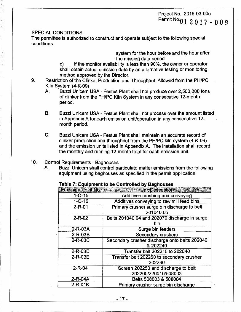
10. Control Requirements - Bag houses A. Buzzi Unicem shall control particulate matter emissions from the following
equipment using baghouses as specified in the permit application.
2-R-02
2-R-03A 2-R-03B 2-R-03C
2-R-03D 2-R-03E
2-R-04
2-R-04A 2-R-01 K
Secondary crusher discharge onto belts 202040 & 202240
Transfer belt 202215 to 202040 Transfer belt 202260 to secondary crusher
202230 . Screen 202250 and discharge to belt
202260/220010/508003 Belts 508003 & 508004
Prima crusher sur e bin dischar e
- 17 -
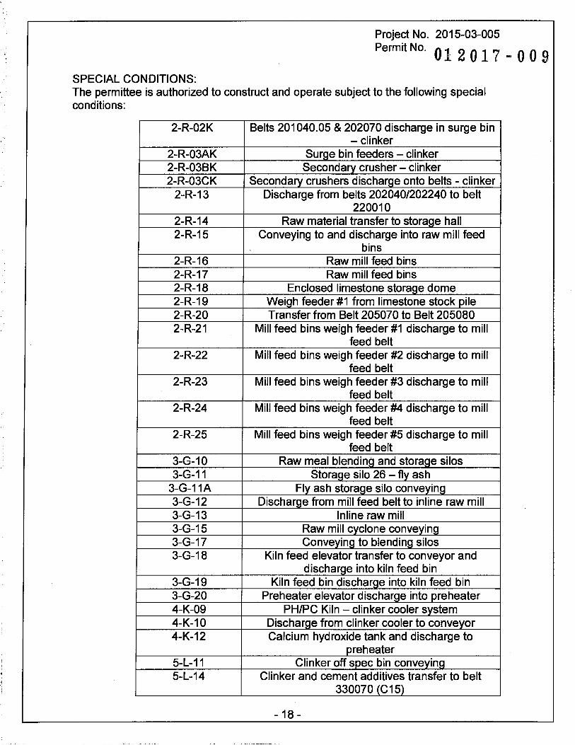
Project No. 2015-03-005
Permit No. 01 2 0 1 7 - 0 0 9
SPECIAL CONDITIONS: The permittee is authorized to construct and operate subject to the following special conditions:
2-R-02K Belts 201040.05 & 202070 discharge in surge bin - clinker
2-R-03AK Surge bin feeders - clinker 2-R-03BK Secondary crusher - clinker 2-R-03CK Secondary crushers discharge onto belts - clinker
2-R-13 Discharge from belts 202040/202240 to belt 220010
2-R-14 Raw material transfer to storage hall 2-R-15 Conveying to and discharge into raw mill feed
bins 2-R-16 Raw mill feed bins 2-R-17 Raw mill feed bins 2-R-18 Enclosed limestone storage dome 2-R-19 Weigh feeder #1 from limestone stock pile 2-R-20 Transfer from Belt 205070 to Belt 205080 2-R-21 Mill feed bins weigh feeder #1 discharge to mill
feed belt 2-R-22 Mill feed bins weigh feeder #2 discharge to mill
feed belt 2-R-23 Mill feed bins weigh feeder #3 discharge to mill
feed belt 2-R-24 Mill feed bins weigh feeder #4 discharge to mill
feed belt 2-R-25 Mill feed bins weigh feeder #5 discharge to mill
feed belt 3-G-10 Raw meal blending and storage silos 3-G-11 Storage silo 26 - fly ash
3-G-11A Fly ash storage silo conveying 3-G-12 Discharge from mill feed belt to inline raw mill 3-G-13 lnline raw mill 3-G-15 Raw mill cyclone convevinQ 3-G-17 ConvevinQ to blendinQ silos 3-G-18 Kiln feed elevator transfer to conveyor and
discharge into kiln feed bin 3-G-19 Kiln feed bin discharge into kiln feed bin 3-G-20 Preheater elevator discharge into preheater 4-K-09 PH/PC Kiln - clinker cooler system 4-K-10 Discharge from clinker cooler to conveyor 4-K-12 Calcium hydroxide tank and discharge to
pre heater 5-L-11 Clinker off spec bin conveying 5-L-14 Clinker and cement additives transfer to belt
330070 (C15)
- 18 -
Project No. 2015-03-005
Permit No.0 1 2 0 1 7 - 0 0 9
SPECIAL CONDITIONS: The permittee is authorized to construct and operate subject to the following special conditions:
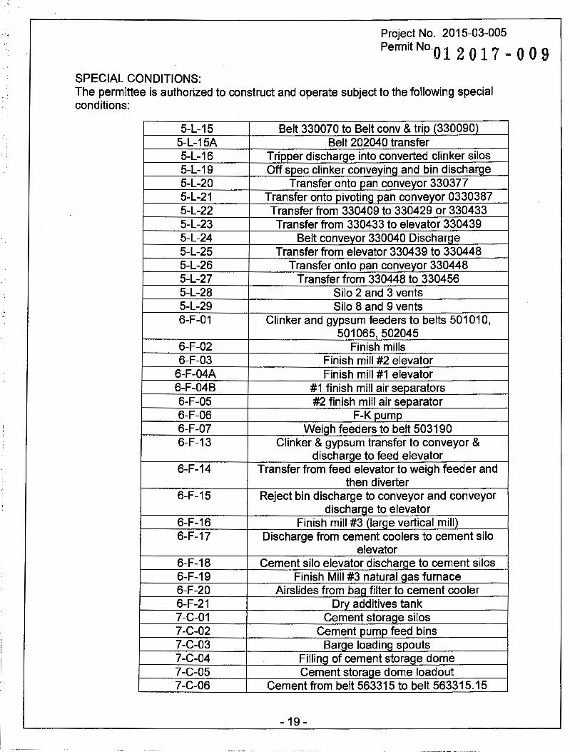
5-L-15 Belt 330070 to Belt conv & trip (330090) 5-L-15A Belt 202040 transfer 5-L-16 Tripper discharge into converted clinker silos 5-L-19 Off spec clinker conveying and bin discharge 5-L-20 Transfer onto pan conveyor 330377 5-L-21 Transfer onto pivoting pan conveyor 0330387 5-L-22 Transfer from 330409 to 330429 or 330433 5-L-23 Transfer from 330433 to elevator 330439 5-L-24 Belt conveyor 330040 Discharge 5-L-25 Transfer from elevator 330439 to 330448 5-L-26 Transfer onto pan conveyor 330448 5-L-27 Transfer from 330448 to 330456 5-L-28 Silo 2 and 3 vents 5-L-29 Silo 8 and 9 vents 6-F-01 Clinker and gypsum feeders to belts 501010,
501065,502045 6-F-02 Finish mills 6-F-03 Finish mill #2 elevator
6-F-04A Finish mill #1 elevator 6-F-04B #1 finish mill air separators 6-F-05 #2 finish mill air separator 6-F-06 F-K pump 6-F-07 Weigh feeders to belt 503190 6-F-13 Clinker & gypsum transfer to conveyor &
discharge to feed elevator 6-F-14 Transfer from feed elevator to weigh feeder and
then diverter 6-F-15 Reject bin discharge to conveyor and conveyor
discharge to elevator 6-F-16 Finish mill #3 (large vertical mill) 6-F-17 Discharge from cement coolers to cement silo
elevator 6-F-18 Cement silo elevator discharge to cement silos 6-F-19 Finish Mill #3 natural gas furnace 6-F-20 Airslides from bag filter to cement cooler 6-F-21 Dry additives tank 7-C-01 Cement storage silos 7-C-02 Cement pump feed bins 7-C-03 Barge loading spouts 7-C-04 Filling of cement storage dome 7-C-05 Cement storage dome loadout 7-C-06 Cement from belt 563315 to belt 563315.15
- 19 -
SPECIAL CONDITIONS:
Project No. 2015-03-005 Permit No. O l
·2017-009
The permittee is authorized to construct and operate subject to the following special conditions:
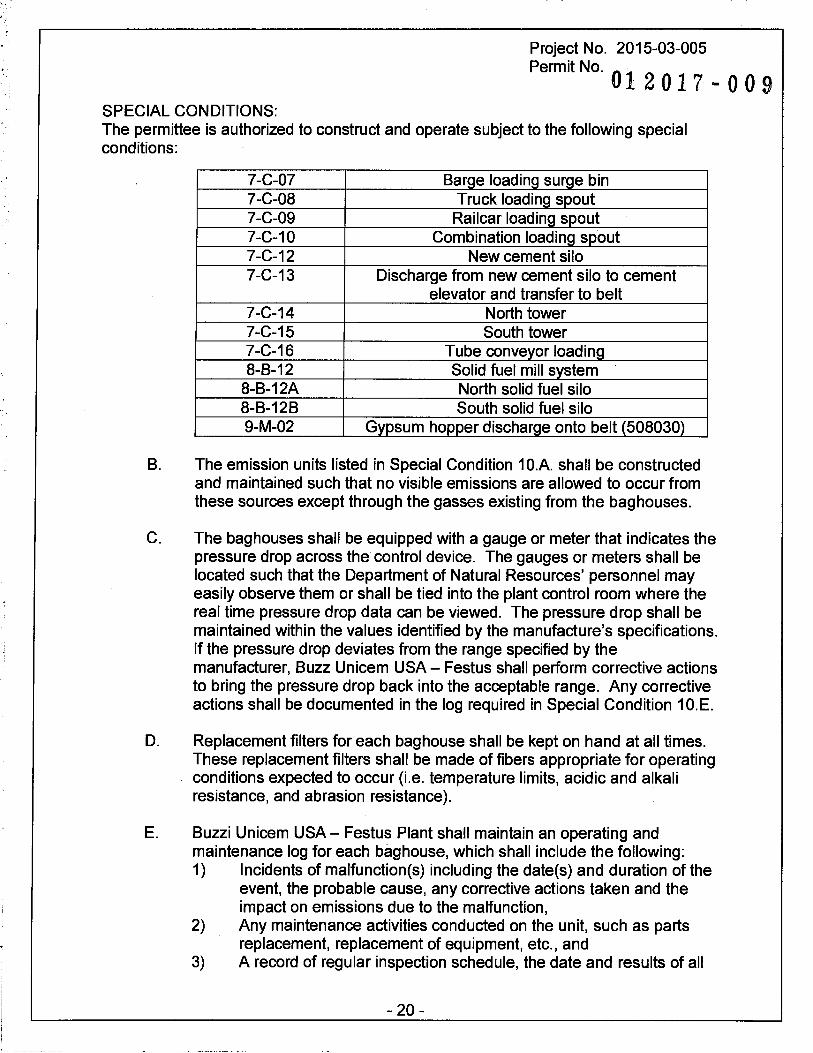
7-C-07 Barge loading surge bin 7-C-08 Truck loading spout 7-C-09 Railcar loading spout 7-C-10 Combination loading spout 7-C-12 New cement silo 7-C-13 Discharge from new cement silo to cement
elevator and transfer to belt 7-C-14 North tower 7-C-15 South tower 7-C-16 Tube conveyor loading 8-8-12 Solid fuel mill system
8-B-12A North solid fuel silo 8-B-128 South solid fuel silo 9-M-02 Gypsum hopper discharge onto belt (508030)
B. The emission units listed in Special Condition 1 O.A. shall be constructed and maintained such that no visible emissions are allowed to occur from these sources except through the gasses existing from the baghouses.
C. The baghouses shall be equipped with a gauge or meter that indicates the pressure drop across the control device. The gauges or meters shall be located such that the Department of Natural Resources' personnel may easily observe them or shall be tied into the plant control room where the real time pressure drop data can be viewed. The pressure drop shall be maintained within the values identified by the manufacture's specifications. If the pressure drop deviates from the range specified by the manufacturer, Buzz Unicem USA - Festus shall perform corrective actions to bring the pressure drop back into the acceptable range. Any corrective actions shall be documented in the log required in Special Condition 1 O.E.
D. Replacement filters for each baghouse shall be kept on hand at all times. These replacement filters shall be made of fibers appropriate for operating conditions expected to occur (i.e. temperature limits, acidic and alkali resistance, and abrasion resistance).
E. Buzzi Unicem USA- Festus Plant shall maintain an operating and maintenance log for each baghouse, which shall include the following: 1) Incidents of malfunction(s) including the date(s) and duration of the
event, the probable cause, any corrective actions taken and the impact on emissions due to the malfunction,
2) Any maintenance activities conducted on the unit, such as parts replacement, replacement of equipment, etc., and
3) A record of regular inspection schedule, the date and results of all
- 20 -

Project No. 2015-03-005 Permit No.
012017-009 SPECIAL CONDITIONS: The permittee is authorized to construct and operate subject to the following special conditions:
inspections including any actions or maintenance activities that result from that inspection.
11. Placement of Sources and Buildings Buzzi Unicem USA - Festus Plant shall submit new modeling files to the Air Pollution Control Program for further analysis should the placement of emission units and buildings change from the configuration submitted with this permit application.
12. Haul Road Control - Paving A. Buzzi Unicem USA - Festus Plant shall pave, or maintain as paved, the
following haul roads with asphalt, concrete, or other materials approved by the Missouri Air Pollution Control Program.
Table 8: Paved Haul Road List Road ID Description 1-Q-07A Clay: Entrance to Storage Pile 1-Q-11A Purchased Sand & Raw Material Pile 1-Q-11 E Bottom Ash Entry Pile 1-Q-11 F To Fly Ash Silo 4-K-11 Calcium Hydroxide Entrance to Tank 4-K-13 Ammonia Hydroxide Entrance to Tank 5-L-10A Clinker Barge to Pile 5-L-31 Clinker from Storage Pile to Crusher 7-C-11 Cement Hauling from Silo
8-B-03A Coke/Coal Entry Pile 8-B-03C Alternative Fuels Truck Delivery
B. Maintenance and repair of the road surface shall be conducted as necessary to ensure that the physical integrity of the pavement is adequate to achieve control of fugitive emissions from these areas while the plant is operating.
C. Buzzi Unicem USA - Festus Plant shall periodically water, wash, or otherwise clean all of the paved portions of the haul roads as necessary to achieve control of fugitive emissions from these areas while the plant is operating.
D. The silt content on the paved haul roads shall not exceed 3.0 g/m2. Buzzi
Unicem USA - Festus plant shall test for the silt content of the clay haul road from entrance to storage pile (1-Q-07A), the cement hauling from silos (7-C-11), and clinker hauling from storage pile to crusher (5-L-31) to ensure compliance with the silt content limit.
- 21 -
SPECIAL CONDITIONS:
Project No. 2015-03-005 Permit No.
012017-009
The permittee is authorized to construct and operate subject to the following special conditions:
E. The tests required in Special Condition 12.D shall be conducted in accordance with ASTM c136 method or another method approved by the Director. Testing shall not be performed immediately after cleaning. If there is a regular cleaning schedule, testing shall be performed some point between midpoint and end of the cleaning cycle. A summary of the testing method is found in Appendix C of AP-42. Testing shall be performed according to the following schedule. 1) Initial testing shall be performed within 180 days of the installation
exceeding the clinker production limit of 2,220,000 tpy in Permit No. 122005-005A;
2) Thereafter, testing shall be conducted once a quarter until there are three (3) consecutive quarter with no exceedances of the silt content limit in Special Condition 12.D.
3) Thereafter, the frequency and method of the cleaning cycle used during the compliant silt content testing shall be used to maintain compliance with the 3.0 g/m2 silt content limit in Special Condition 12.D.
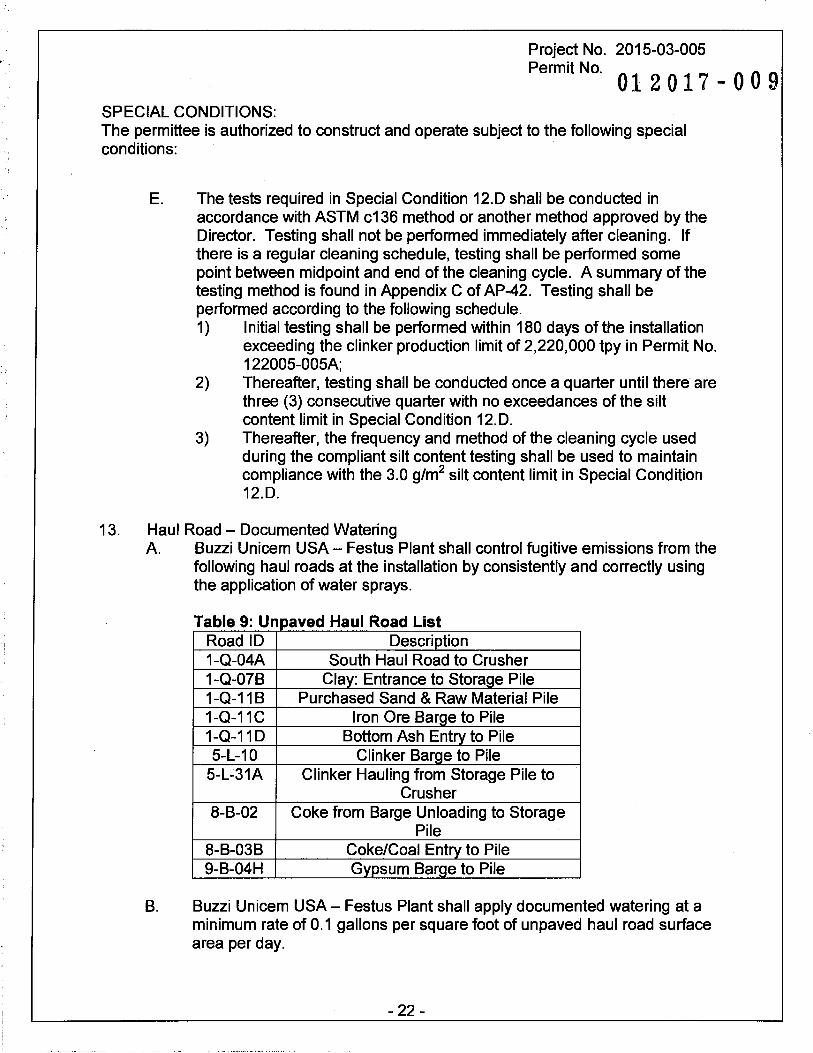
13. Haul Road - Documented Watering A. Buzzi Unicem USA - Festus Plant shall control fugitive emissions from the
following haul roads at the installation by consistently and correctly using the application of water sprays.
T bl 9 U d H IR d L" t a e . npave au oa IS . Road ID Description 1-Q-04A South Haul Road to Crusher 1-Q-078 Clay: Entrance to Storage Pile 1-Q-11 B Purchased Sand & Raw Material Pile 1-Q-11C Iron Ore Barge to Pile 1-Q-11 D Bottom Ash Entry to Pile 5-L-10 Clinker Barge to Pile
5-L-31A Clinker Hauling from Storage Pile to Crusher
8-8-02 Coke from Barge Unloading to Storage Pile
8-8-038 Coke/Coal Entry to Pile 9-B-04H Gypsum Barge to Pile
B. Buzzi Unicem USA - Festus Plant shall apply documented watering at a minimum rate of 0.1 gallons per square foot of unpaved haul road surface area per day.
- 22 -
SPECIAL CONDITIONS:
Project No. 2015-03-005 Permit No.
012017·-00!t
The permittee is authorized to construct and operate subject to the following special conditions:
C. Water shall be applied at least once per twenty-four hours or whenever conditions exist which would cause visible emissions to enter the ambient air beyond the property boundary.
D. In lieu of the 0.1 gallons per square foot per day watering rate as listed in Special Condition 13.B., Buzzi Unicem USA- Festus Plant may choose to perform a site-specific watering control study to determine a new watering rate. Buzzi Unicem USA - Festus Plant shall submit a plan for the site specific watering control study to the Air Pollution Control Program for review and approval before performing the study. After performing the study, the installation shall submit the results to the Air Pollution Control Program for approval before using the new watering rate.
E. A quarter inch or more of rainfall, during the preceding twenty-four hours shall substitute for one daily water application.
F. Watering may be suspended when the ground is frozen, during periods of freezing conditions when watering would be inadvisable for traffic safety reasons, or when there will be no traffic on the roads.
G. Buzzi Unicem USA- Festus Plant shall maintain a log that documents daily water applications. This log shall include, at a minimum, haul road being watered, date and volume of water application, surface area of each road being watered, watering rate in gallons per square foot of unpaved haul road surface area, and rationale if water is not applied.
14. Haul Road- Speed Limit A. Buzzi Unicem USA - Festus plant shall control fugitive emissions from all
unpaved haul roads by limiting its average truck speed to no more than 25 miles per hour.
B. Buzzi Unicem USA- Festus plant shall show compliance with Special Condition 14.A. by implementing a documented training program for its truck drivers on the average truck speed. A copy of the tra·ining program shall be kept onsite and be made available to Department of Natural Resources personnel upon request.
C. Buzzi Unicem USA - Festus plant shall maintain a log for the training program that include, at a minimum, the following. 1) The name of the drivers 2) The date of the training 3) Signature of the drivers
- 23 -
Project No. 2015-03-005
Permit No. 01 2 0 1 7 - 0 0 9
SPECIAL CONDITIONS: The permittee is authorized to construct and operate subject to the following special conditions:
D. Buzzi Unicem USA- Festus plant shall train its drivers once every calendar year and whenever there are new drivers on the unpaved haul roads.
15. Enclosure Control A. Buzzi Unicem USA - Festus Plant shall control fugitive emissions from the
clay and substitute storage piles (1-Q-08) by constructing a two-sided enclosure with a roof.
8. Buzzi Unicem USA - Festus Plant shall control fugitive emissions from the clinker storage piles (5-L-08) by constructing a three -sided enclosure with a roof.
16. Record Keeping and Reporting Requirements A. Buzzi Unicem USA - Festus Plant shall maintain all records required by
this permit for not less than five years and shall make them available immediately to any Missouri Department of Natural Resources' personnel upon request.
8. Buzzi Unicem USA- Festus Plant shall report to the Air Pollution Control Program's Compliance/Enforcement Section, P.O. Box 176, Jefferson City, MO 65102, no later than 10 days after the end of the month during which any record required by this permit shows an exceedance of a limitation imposed by this permit.
- 24 -

REVIEW OF APPLICATION FOR AUTHORITY TO CONSTRUCT AND OPERATE SECTION (8) REVIEW
Project Number: 2015-03-005 Installation ID Number: 099-0002
Installation Address: Buzzi Unicem USA - Festus Plant 1000 River Cement Road Festus, MO 63028
Jefferson County, S40, T23N, R6E
Permit Number: 01 201 7 - O O 9
Parent Company: River Cement Company 100 Brodhead Road Bethlehem, PA 18017-8989
REVIEW SUMMARY
• Buzzi Unicem USA - Festus Plant has applied for authority to increase its clinker production limit from 2,220,000 tons per year to 2,500,000 tons per year.
• The application was deemed complete on March 3, 2015.
• HAP emissions are expected from the proposed equipment. HAPs of concern from this process are beryllium, lead, and hydrogen chloride. However, the HAP emitting units at the installation are subject to the requirements of a MACT standard. Therefore, a Missouri Section (9) review is not required.
• 40 CFR 60, Subpart 000, Standards of Performance for Nonmetallic Mineral Processing Plants, and 40 CFR 60 Subpart F, Standards of Performance for Portland Cement Plants, of the NSPS applies to the installation.
• 40 CFR 63, Subpart LLL, National Emission Standards for Hazardous Air Pollutants from the Portland Cement Manufacturing Industry, applies to some of the equipment at the installation.
• Various types of dust control methods are being used to control the particulate emissions from the equipment and activities in this permit.
• This review was conducted in accordance with Section (8) of Missouri State Rule 10 CSR 10-6.060, Construction Permits Required. Emissions increase of CO and C02e are above de minimis levels.
• This installation is located in Jefferson County, a nonattainment area for the 8-hour ozone standard and the PM2.5 standard and an attainment area for all other criteria pollutants. Part of Jefferson County is a nonattainment area for lead. The installation is not located in the Jefferson County lead nonattainment area.
- 25 -
• This installation is on the List of Named Installations found in 10 CSR 10-6.020(3)(8), Table 2. The installation is classified as item number 3. Portland cement plants. The installation's major source level is 100 tons per year and fugitive emissions are counted toward major source applicability.
• Ambient air quality modeling was performed to determine the ambient impact of CO.
• Emissions testing and the installation of CEMS and CPMS are required for some of the equipment as a part of this permit. Testing may also be required as part of other state, federal or applicable rules.
• A Part 70 Operating Permit application is required for this installation within one year after exceeding the 2.22 million tons per year of clinker production.
• Approval of this permit is recommended with special conditions.
INSTALLATION DESCRIPTION
Buzzi Unicem currently operates a Portland cement manufacturing installation in Festus, Missouri that performs quarrying and crushing of raw materials, and processing of these materials into Portland cement via a PH/PC kiln system (4-K-09) These systems are described in detail below and consist of equipment to prepare raw material into pyre-process kiln feed (Raw Grinding), process kiln feed into clinker (Burning), prepare raw fuel for combustion (Fuel Grinding), and process clinker into cement (Finish Grinding).
• Quarry - Crushing Limestone is quarried on the plant property; corrective materials, such as sandstone, clay, iron-rich minerals, silica-bearing materials, and other materials are received from off-site sources. Raw materials are introduced to a single gyratory-type primary crusher that crushes these to a material size of less than six (6) inches in diameter. From this unit, material is conveyed into two (2) parallel hammer-type secondary crushers that further reduce the maximum particle size to less than 1 inch in diameter. The materials are then individually conveyed via belt conveyors to several silos/bins for temporary storage. From these storage units the raw materials are extracted and conveyed to the PH/PC kiln system for processing.
• Raw Grinding The crushed raw materials are extracted from storage in pre-determined ratios and conveyed via a belt conveyor into a Raw Grinding system, where the combined materials are dried and pulverized. The grinding takes place in a tubular-type ball mill, where the materials are reduced to a fine powder. The drying and the separation of the finished product take place in a dynamic separator. A coal/cokefired furnace provides the heat required for drying the raw materials. In the dynamic separator the hot air stream is forced through sets of rotating blades that remove oversized particles that are subsequently returned to the mill system for further
- 26 -
grinding. Sufficiently ground material - kiln feed - exits the system and is conveyed pneumatically for blending into 4 kiln feed silos, common for both Raw Grinding systems, for temporary storage. Process air and water vapor from the mill and the separator are treated in bag houses prior to release to the atmosphere.
• Clinker Burning From the kiln feed silos, the kiln feed is pneumatically conveyed into the PH/PC kiln system for pyre-processing into cement clinker nodules. The primary fuel is coal and/or coke. The kiln system can also be fired with natural gas. This fuel is typically used only during kiln start-up or during upsets as supplemental fuel. The gas is hard-piped to the kiln floor and fed via a separate firing lance into the main burner assembly at the hot end of the kiln.
As the kiln feed is gravity-conveyed through the kiln it is progressively heated and undergoes calcination and sintering processes. When the material reaches the hot end of the kiln it has completed a chemical transformation into Portland cement clinker nodules, typically sized between % - inch and 2-inches in diameter. The clinker nodules are deposited directly from the hot-end of the kiln into the clinker cooler system.
• Clinker Cooling Clinker discharged from the kiln passes through a forced-air, reciprocating Clinker Cooler. The majority of the spent cooling air is forced into the hot end of the kiln to provide the oxygen for combustion. A portion of the heated air is also diverted to the fuel grinding process for use as drying air. Excess spent air is passed through fabric filters before venting to atmosphere. The cooled clinker is conveyed to either a covered storage area or to storage silos that feed the Finish Grinding process. From the covered clinker storage building, clinker is reclaimed via underground vibrating feeders and conveyed via belt conveyors, bucket elevators and drag chain conveyors to the clinker storage silos.
• Fuel Grinding Solid fuel is currently delivered to the installation and placed in stockpiles for storage. The fuel is reclaimed by front-end loaders and conveyed via conveyor belts to intermediate storage tanks. The fuel is reclaimed from each intermediate tank and conveyed by drag chain and screw conveyors to a tubular-type ball mill for drying and grinding. A slipstream of hot air from either clinker cooler is diverted to the mill for use as both drying and sweep air. Ground fuel entrained in the drying/sweep air is transported, via the air stream, to a dynamic separator. In the separator, the air stream will pass through sets of rotating blades that will remove oversized particles of solid fuel, which will be returned to the mill system for further grinding. Process air and water vapor from the mill and the separator are treated in fabric filters prior to release into the atmosphere. The finely ground fuel is conveyed to, and collected in, two (2) pulverized fuel storage tanks, one (1) tank providing fuel to each kiln system. The pulverized fuel is metered from the storage tanks and is conveyed to the burner of each kiln via pneumatic conveying. The mix of fuel and conveying air is deployed through the burner into the kiln's combustion zone.
- 27 -

• Finish Grinding In the Finish Grinding process, gypsum is ground with clinker to produce cement. Gypsum is received at the plant by barge, and conveyed by trucks to an outdoor gypsum storage pile. Gypsum is then unloaded from the pile into a hopper and transferred via belt conveyors and bucket elevators to gypsum storage silos.
Clinker and gypsum are extracted from their respective storage silos, metered and fed in predetermined proportions into a tubular-type mill. A high molecular weight organic compound solution is also injected to the mill to aid in the grinding process. The clinker/gypsum blend is introduced to the mill where it is pulverized. Sweep air is introduced to the mill to entrain ground cement particles and carry them to the cement separator system. In the separator, the air stream passes through sets of rotating blades that remove oversized particles of clinker and gypsum and causes them to return to the mill system for further grinding. Sufficiently ground particles of clinker and gypsum are transported by the air stream into fabric bag filters; the clean air passes through the fabric bag and is released into the atmosphere, while the material particles are trapped on the outside of the fibers of the fabric bag. Jet pulses of compressed air are periodically forced inside the fabric bag, causing the material particles to dislodge and fall into the fabric filter hopper, where they are collected and conveyed via rotating screw conveyors to either a cement cooler or to a pneumatic conveying system. The ground clinker and gypsum particles mix, or Portland cement, are processed for cooling through a cement cooler for temperature control, and are then pneumatically conveyed to either cement storage silos or to a cement storage monolithic dome.
The Portland cement is gravity withdrawn, and shipped off-site via barges, railcars and trucks. Air-gravity conveyors are used for truck loading and railcar operations; barges are loaded using either a pneumatic conveying system or belt conveyors.
Buzzi Unicem, formerly known as River Cement Company, is considered to be an existing major source of air pollutants for New Source Review (NSR) purposes and a Part 70 source for Operating Permit purposes. The following NSR permits and amendments have been issued to River Cement Company from the Air Pollution Control Program.
Table 10: New Source Review Permits and Amendments tPBrifit.:Niu:ftJ;iii'ti!ri! ~11:ii'it:
032013_003
Extension of time to construct the equipment permitted in Permit 032013-003.
102014-001
032013-003A
032013-003
Section (5) permit for the addition of screens and conveyors to the existin seconda crushin and screenin s stem. Amendment to Permit 032013-003 to revise the PM10
testing requirements and to increase the sulfur content limit for the alternative fuels. Section (5) permit for the use of alternative fuel in place of a portion of the petroleum coke and coal fuel for the
reheater/ recalciner cement kiln.
- 28 -
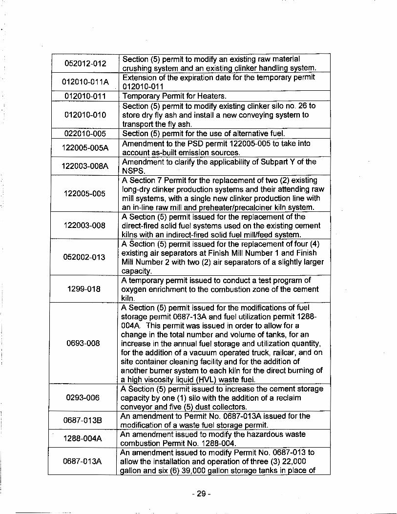
052012-012 Section (5) permit to modify an existing raw material crushing system and an existing clinker handlina system.
012010-011A Extension of the expiration date for the temporary permit 012010-011
012010-011 Temporary Permit for Heaters. Section (5) permit to modify existing clinker silo no. 26 to
012010-010 store dry fly ash and install a new conveying system to transport the fly ash.
022010-005 Section (5) permit for the use of alternative fuel.
122005-005A Amendment to the PSD permit 122005-005 to take into account as-built emission sources.
122003-008A Amendment to clarify the applicability of Subpart Y of the NSPS. A Section 7 Permit for the replacement of two (2) existing
122005-005 long-dry clinker production systems and their attending raw mill systems, with a single new clinker production line with an in-line raw mill and preheater/precalciner kiln system. A Section (5) permit issued for the replacement of the
122003-008 direct-fired solid fuel systems used on the existing cement kilns with an indirect-fired solid fuel mill/feed system. A Section (5) permit issued for the replacement of four (4)
052002-013 existing air separators at Finish Mill Number 1 and Finish Mill Number 2 with two (2) air separators of a slightly larger capacity. A temporary permit issued to conduct a test program of
1299-018 oxygen enrichment to the combustion zone of the cement kiln. A Section (5) permit issued for the modifications of fuel storage permit 0687-13A and fuel utilization permit 1288-004A. This permit was issued in order to allow for a change in the total number and volume of tanks, for an
0693-008 increase in the annual fuel storage and utilization quantity, for the addition of a vacuum operated truck, railcar, and on site container cleaning facility and for the addition of another burner system to each kiln for the direct burning of a hiah viscosity liquid (HVL) waste fuel. A Section (5) permit issued to increase the cement storage
0293-006 capacity by one (1) silo with the addition of a reclaim conveyor and five (5) dust collectors.
0687-0138 An amendment to Permit No. 0687-013A issued for the modification of a waste fuel storaae permit.
1288-004A An amendment issued to modify the hazardous waste combustion Permit No. 1288-004. An amendment issued to modify Permit No. 0687-013 to
0687-013A allow the installation and operation of three (3) 22,000 aallon and six (6) 39,000 aallon storaae tanks in place of
- 29 -
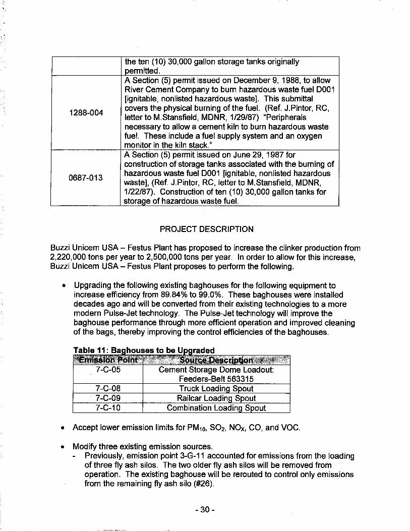
the ten (10) 30,000 gallon storage tanks originally permitted. A Section (5) permit issued on December 9, 1988, to allow River Cement Company to burn hazardous waste fuel 0001 [ignitable, nonlisted hazardous waste]. This submittal
1288-004 covers the physical burning of the fuel. (Ref. J.Pintor, RC, letter to M.Stansfield, MDNR, 1/29/87) "Peripherals necessary to allow a cement kiln to burn hazardous waste fuel. These include a fuel supply system and an oxygen monitor in the kiln stack." A Section (5) permit issued on June 29, 1987 for construction of storage tanks associated with the burning of
0687-013 hazardous waste fuel 0001 [ignitable, nonlisted hazardous waste], (Ref. J.Pintor, RC, letter to M.Stansfield, MDNR, 1/22/87). Construction of ten (10) 30,000 gallon tanks for storage of hazardous waste fuel.
PROJECT DESCRIPTION
Buzzi Unicem USA - Festus Plant has proposed to increase the clinker production from 2,220,000 tons per year to 2,500,000 tons per year. In order to allow for this increase, Buzzi Unicem USA- Festus Plant proposes to perform the following.
• Upgrading the following existing baghouses for the following equipment to increase efficiency from 89.84% to 99.0%. These baghouses were installed decades ago and will be converted from their existing technologies to a more modern Pulse-Jet technology. The Pulse-Jet technology will improve the baghouse performance through more efficient operation and improved cleaning of the bags, thereby improving the control efficiencies of the bag houses.
Table 11: Ba houses to be U raded i&'rttiJ.itoliMlhlntt: fa~~f#ffgti~W,}IT1'.SOPtCllJ,;QeJe:ri ··'tt
7-C-05 Cement Storage Dome Loadout: Feeders-Belt 563315
7-C-08 7-C-09 7-C-10
• Accept lower emission limits for PM10, S02, NOx, CO, and VOC.
• Modify three existing emission sources. Previously, emission point 3-G-11 accounted for emissions from the loading of three fly ash silos. The two older fly ash silos will be removed from operation. The existing baghouse will be rerouted to control only emissions from the remaining fly ash silo (#26).
- 30 -

Previously, the clinker and gypsum weigh feeders both transferred material to either Belt 330200 (emission point 6-F-07) or Belt 503090 (emission point 6-F-08), which both transferred material to Belt 503190. The clinker and gypsum weight feeders will be modified to transfer material to Belt 503080 which will unload to Belt 503190. The transfer of material to and from Belt 503080 will be controlled by the two existing bag houses for 6-F-07. Emission point 6-F-08 (Belt 503090) will be permanently removed from service. Emission Point 7-C-02 previously accounted for the emissions from two cement pumps (IDs 563175 and 563200), each controlled by its own baghouse (IDs 563180 and 563205). Pump 563175 and its associated baghouse will be removed from service. The throughput limit for the remaining equipment will be set at 100,000 tons per year.
• Modify six existing haul road routes to shorten the distance ·traveled to deliver raw materials to the plant. The haul roads to be modified are 1-Q-07 A, 1-Q-07B, 1-Q-11A, 1-Q-11B, 1-Q-11D, and 1-Q-11E.
• Install additional air pollution control technologies for S02 and NOx. Buzzi Unicem USA - Festus Plant was previously granted a permit for an ammonium hydroxide injection system and a calcium hydroxide injection system under Construction Permit 122005-005A, but they were never constructed. Since more than two-years have elapsed since the issuance of this permit, the control devices will need to be included in this permit. The ammonium hydroxide injection system controls emissions of NOx while the calcium hydroxide injection system controls emissions of S02. The facility may need to use these devices to maintain compliance with the NOx and S02 limits for the PH/PC Kiln (4-K-09). Since the facility is required to install CEMS to monitor the NOx and S02 emissions from the PH/PC kiln, it should not matter if the facility actually used these devices if it can employ other measures, such as operational adjustments, to meet these limits. Therefore, the use of these injection systems is not required as a permit condition. Furthermore, the facility does not want to limit the chemical to just ammonium hydroxide and calcium hydroxide. It would like the option to use other chemicals.
• Permanently decommissioning the following sources.
Table 12: Decommissioned Sources '""';1=;o=~p=c~=-=:::~=iip=]1=:so=j1;=:Ji=,::::-;:1j:;;7,(t:;,;clt"7.""fl"7~'iit:-;:,;i~~~~~Tu,:-;,;~,1~1;,l=ti
1-Q-04C North haul road to crusher 5-L-11 6-F-08 6-F-21 6-F-22 9-M-06 Airalon stora e tank.
Furthermore, during the review of this project, Buzzi Unicem USA - Festus Plant discovered that two baghouses have been added to existing sources already controlled
- 31 -
by baghouses to better control fugitive emissions, but these two baghouses have never been permitted. Therefore, these two additional baghouses will be added to this permit. One of these baghouse controls the raw mill feed bin weigh feeders (emission points 2-R-21 to 2-R-25) and the other controls clinker silos 8 and 9 (emission point 5-L-029).
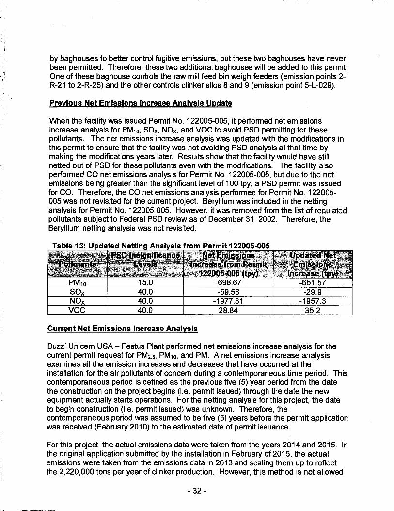
Previous Net Emissions Increase Analysis Update
When the facility was issued Permit No. 122005-005, it performed net emissions increase analysis for PM10, SOx, NOx, and VOC to avoid PSD permitting for these pollutants. The net emissions increase analysis was updated with the modifications in this permit to ensure that the facility was not avoiding PSD analysis at that time by making the modifications years later. Results show that the facility would have still netted out of PSD for these pollutants even with the modifications. The facility also performed CO net emissions analysis for Permit No. 122005-005, but due to the net emissions being greater than the significant level of 100 tpy, a PSD permit was issued for CO. Therefore, the CO net emissions analysis performed for Permit No. 122005-005 was not revisited for the current project. Beryllium was included in the netting analysis for Permit No. 122005-005. However, it was removed from the list of regulated pollutants subject to Federal PSD review as of December 31, 2002. Therefore, the Beryllium netting analysis was not revisited.
Table 13: U dated Nettin Anal sis from Permit 122005-005 .~x
PM10 15.0 -698.67 -651.57 SOx 40.0 -59.58 -29.9 NOx 40.0 -1977.31 -1957.3 voe 40.0 28.84 35.2
Current Net Emissions Increase Analysis
Buzzi Unicem USA - Festus Plant performed net emissions increase analysis for the current permit request for PM2.5, PM10, and PM. A net emissions increase analysis examines all the emission increases and decreases that have occurred at the installation for the air pollutants of concern during a contemporaneous time period. This contemporaneous period is defined as the previous five (5) year period from the date the construction on the project begins (i.e. permit issued) through the date the new equipment actually starts operations. For the netting analysis for this project, the date to begin construction (i.e. permit issued) was unknown. Therefore, the contemporaneous period was assumed to be five (5) years before the permit application was received (February 2010) to the estimated date of permit issuance.
For this project, the actual emissions data were taken from the years 2014 and 2015. In the original application submitted by the installation in February of 2015, the actual emissions were taken from the emissions data in 2013 and scaling them up to reflect the 2,220,000 tons per year of clinker production. However, this method is not allowed
- 32 -
under PSD regulations. Therefore, the facility updated its application to use the 2014 and 2015 average emissions instead, without scale-ups.
After the netting analysis has determined the amount of actual or potential emissions for all of the units where increases and decreases have occurred, or will occur during this period, the increases are added together and the decreases are subtracted from this total. If the resulting level of emissions from the netting analysis is below the significant level for that air pollutant, then the project is evaluated as a de minimis review instead of a PSD review.
Net Emissions Increase Analysis for PM2.5, PM10, and PM
This project involves an increase in the maximum clinker production capacity of the installation, therefore, there is an increased utilization associated with most of the existing equipment at the installation that must be included in the netting analysis. The installation proposed the removal of several pieces of equipment and activities, which are listed in Table 12. Special conditions are incorporated into this permit to insure that these equipment and activities are permanently removed from operations. The facility also suggested the modification of several pieces of control devices to increase the control efficiency. This permit also includes special conditions that insure the completion of these modifications.
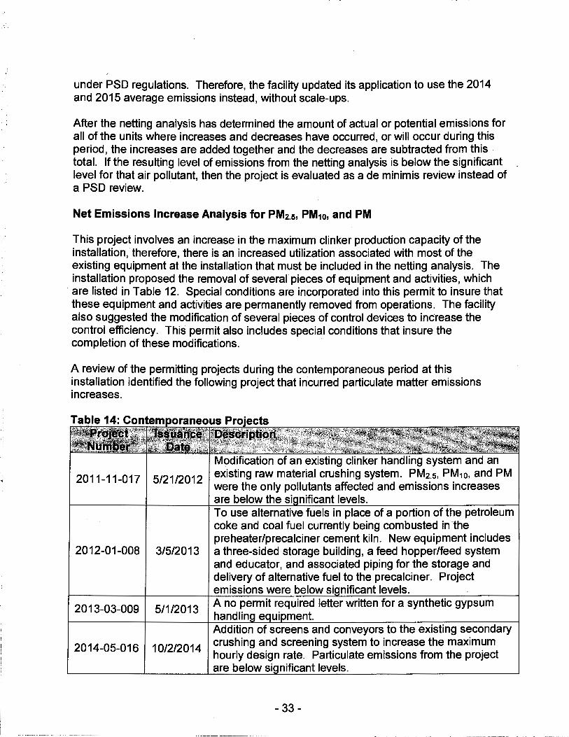
A review of the permitting projects during the contemporaneous period at this installation identified the following project that incurred particulate matter emissions increases.
2011-11-017 5/21/2012
2012-01-008 3/5/2013
2013-03-009 5/1/2013
2014-05-016 10/2/2014
Modification of an existing clinker handling system and an existing raw material crushing system. PM2.5, PM10, and PM were the only pollutants affected and emissions increases are below the si nificant levels. To use alternative fuels in place of a portion of the petroleum coke and coal fuel currently being combusted in the preheater/precalciner cement kiln. New equipment includes a three-sided storage building, a feed hopper/feed system and educator, and associated piping for the storage and delivery of alternative fuel to the precalciner. Project emissions were below si nificant levels. A no permit required letter written for a synthetic gypsum handlin e ui ment. Addition of screens and conveyors to the existing secondary crushing and screening system to increase the maximum hourly design rate. Particulate emissions from the project are below si nificant levels.
- 33 -
A review of all permitting projects submitted by the installation during the contemporaneous period did not identify any other emission units involving any increases or decreases in particulate emissions. Net PM2.s, PM10, and PM emissions were shown to be less than their respective significant levels (10.0 tpy PM2.s, 15.0 tpy PM10, and 25.0 tpy PM). Therefore, this review was conducted in accordance with Section (5) of Missouri State Rule 10 CSR 10-6.060 for these pollutants.
Emissions Increase Analysis for SOx, NOx, voe, and CO
The emissions increase is the potential emissions after this project minus the BAE. Results show that emissions for SOx, NOx, and voe are less than the significant levels
Emissions Increase and Net Emissions Increase Analysis for CO and C02e
The first step is to determine if the CO and C02e from the modification will result in a significant increase in emissions of CO and C02e. The emissions increase is the potential emissions after this project minus the BAE. Calculations, which are further discussed below in the "Emissions/Controls Evaluation," show that for both CO and C02e, the emissions increases are greater than their respective significance levels. The second step is to determine if the net emissions increase for CO and C02e are greater than the significance levels. During the contemporaneous period, there were no creditable emissions decreases for either CO or C02e. Therefore, the net emissions increase for CO and CO2 are still greater than the significance levels.
For CO and C02e, this review was conducted in accordance with Section (8) of Missouri State Rule 10 CSR 10-6.060. For all other pollutants, this review was conducted in accordance with Section (5) of Missouri State Rule 1 O CSR 10-6.060.
EMISSIONS/CONTROLS EVALUATION
PM2.s, PM10, PM, S02, NOx, VOC, CO, CO2, C02e, and hydrogen chloride are the primary emissions in the manufacture of Portland cement. Small quantities of ammonia, and chlorine also may be emitted. Emissions may also include residual materials from the fuel and raw materials or products of incomplete combustion that are considered to be hazardous. Also, raw material feeds and fuels typically contain trace amounts of heavy metals that may be emitted as PM or vapor.
Sources of particulates at cement plants include (1) quarrying and crushing, (2) raw material storage, (3) grinding and blending, (4) clinker production, (5) finish grinding, and (6) packaging and loading. Additional sources are raw material storage piles, conveyors, storage silos and unloading facilities. The kiln is a combustion source; Particulates from the kiln consists of both a filterable and a condensable fraction. Particulate emission factors were from different sources. Some came from the following sections of the EPA document AP-42, Compilation of Air Pollutant Emission Factors, Fifth Edition.
- 34 -

Section 11.19.2
Section 11.6 Section 11. 12 Section 13.2.1 Section 13.2.2 Section 13.2.4 Section 1.4
Crushed Stone Processing and Pulverized Minerals Processing (8/04), Portland Cement Manufacturing (1/95), Concrete Batching (11/03), Paved Roads (1/11) Unpaved Roads (12/03), Aggregate Handling and Storage Piles (1/95), and Natural Gas Combustion {7 /98).
The wind erosion particulate emission factor is from current Air Pollution Control Program guidance on storage piles. The particulate emission factor for vehicular activity around the storage pile was obtained from the Noyes Data Corp. book, Orlemann, et al.1983, Fugitive Dust Control ..
Emission factors for the crushing and screening of clay, ore transfer, sand transfer and screening, cement loadout and transfer, coal unloading and crushing, and gypsum conveying were obtained from the EPA Factor Information Retrieval {FIRE) Version 6.23 {SCC Codes: 3-05-009-04, 3-03-023-04, 3-05-025-03, 3-05-025-11, 3-05-006-19, 3-05-006-12, 3-03-003-05, 3-05-010-10, and 3-05-015-04).
Oxides of nitrogen are generated during fuel combustion by oxidation of chemically bound nitrogen in the fuel and by thermal fixation of nitrogen in the combustion air. S02 may be generated both from the sulfur compounds in the raw materials and from sulfur in the fuel. If the combustion reactions do not reach completion, CO and voe can be emitted. Incomplete combustion also can lead to emissions of specific HAPs.
Emission factors for SOx, NOx, CO and VOC for the kiln system are engineering estimates from Buzzi Unicem. Emission factors for the remaining pollutants are from the Portland cement section of AP-42 for both the kiln and the finish mill. The breathing/working loss of VOC emission factors for the gasoline, diesel and kerosene storage tanks were obtained from the EPA FIRE Version 6.21 {SCC Codes: 4-03-010-03, 4-03-010-09, 4-03-010-19, 4-03-010-21, 4-03-010-16 and 4-03-010-18, respectively). Emission factors for the combustion of natural gas were taken from AP-42 Section 1.4, Natural Gas Combustion.
Most of the potential emissions and BAE were calculated using the same emission fact9rs and equations. However, there were some differences and the major ones are listed below.
GHG, including CO2, CH4, and N20 emissions were calculated using equations C-1/C-8 from 40 CFR 98. To calculate C02e emissions, the CO2, CH4, and N20 emissions were multiplied by their respective global warming potentials {GWP) as given in 40 CFR 98 and summed.
• For unpaved haul roads, the facility previously used undocumented watering, which was given 50% control efficiency for particulates. After this project, the facility will be using documented watering as well as keeping its truck speed to
- 35 -
an average of less than 25 mph, which are given 90% control efficiency for particulates.
• For wind erosion, the facility will be constructing a two-sided enclosure with roof, which was given a 50% control efficiency for particulates, and a three-sided enclosure with roof, which was given a 75% control efficiency for particulates.
• For non-particulate emissions, the BAE were calculated using higher emission factors because the facility will be taking a lower emissions limit for this project.
Results of the Net Emissions Increase Analysis are given below. Potential emissions are based on a production limit of 2,500,000 tons per year of clinker. Existing actual emissions are based on production from 2014-2015. The net emissions increase from the project includes all emissions increases and decreases incurred during the contemporaneous period.
PM 25.0 Major 817.7 -369.7 PM10 15.0 Major 534.2 -90.2
PM2.5 10.0 Major 280.7 9.80 SOx 40.0 Major 533 30.2 NOx 40.0 Major 3,330 37.2 voe 40.0 Major 257 9.8 co 100.0 Major 1,605 907.4
GHG (C02e) 75,000 N/D 1,970,299 322.998.3 GHG (mass) 100.0 N/D N/D N/D
HAPs 10.0/25.0 Major N/D N/D
Pb 0.6/0.01 N/D 0.08 0.011 · Hg 0.1 N/D 0.0266 0.003 Be 0.0004 N/D 0.00073 0.0001
Fluorides 3.0 N/D 0.999 0.13 Benzene 10.0/2.0 N/D N/D 2.24 Hydrogen 10.0 N/D N/D 19.60 Chloride
Acenaphthylen 0.01 N/D N/D 0.017 e
Phenanthrene 0.01 N/D N/D 0.055 NIA = Not Applicable; N/D = Not Determined
- 36 -
PERMIT RULE APPLICABILITY
This review was conducted in accordance with Section (8) of Missouri State Rule 10 CSR 10-6.060, Construction Permits Required. Net emissions increase of CO and GHG-C02e is above major levels.
APPLICABLE REQUIREMENTS
Buzzi Unicem USA - Festus Plant shall comply with the following applicable requirements. The Missouri Air Conservation Laws and Regulations should be consulted for specific record keeping, monitoring, and reporting requirements. Compliance with these emission standards, based on information submitted in the application, has been verified at the time this application was approved. For a complete list of applicable requirements for your installation, please consult your operating permit.
GENERAL REQUIREMENTS
• Submission of Emission Data, Emission Fees and Process Information, 10 CSR 10-6.110
o Per 10 CSR 10-6.110(4)(B)2.A., a full EIQ is required annually
• Operating Permits, 1 O CSR 10-6.065
• Restriction of Particulate Matter to the Ambient Air Beyond the Premises of Origin, 10 CSR 10-6.170
• Restriction of Emission of Visible Air Contaminants, 10 CSR 10-6.220
• Restriction of Emission of Odors, 10 CSR 10-6.165
SPECIFIC REQUIREMENTS
• New Source Performance Regulations, 1 O CSR 10-6.070 o Standards of Performance for Nonmetallic Mineral Processing Plants, 40
CFR Part 60, Subpart 000 o Standards of Performance for Portland Cement Plants, 40 CFR Part 60,
Subpart F
• MACT Regulations, 10 CSR 10-6.075 o National Emission Standards for Hazardous Air Pollutants from the
Portland Cement Manufacturing Industry, 40 CFR Part 63, Subpart LLL
- 37 -

• Control of NOxEmissions from Portland Cement Kilns, 10 CSR 10-6.380
• Control of Sulfur Dioxide Emissions, 10 CSR 10-6.261 o Restriction of Emission of Sulfur Compounds, 1 O CSR 10-6.260, has been
rescinded and replaced by 10 CSR 10-6.261 in the code of state regulations. However, 10 CSR 10-6.260 has not yet been removed from the SIP and therefore, remains an enforceable regulation, if applicable.
AMBIENT AIR QUALITY IMPACT ANALYSIS
Ambient air quality modeling was performed to determine the ambient impact of carbon monoxide (CO), hydrogen chloride (HCI), benzene, acenaphthylene, and phenanthrene. For CO, modeling is required because the facility had net emissions increase greater than 100.0 tons per year. For the individual HAPs, the emissions increase is greater than the screening model action level (SMAL). Results show that for all pollutants, the concentration at the nearest property boundary would be less than the regulatory levels. CO was modeled using AERMOD while individual HAPs were modeled using AERSCREEN.
co 376.2 2000 1-Hour co 206.3 500 8-Hour
2.7 180 24-hour 0.45 20 Annual
Benzene 0.309 1.0 24-hour 0.052 1.2 Annual
0.00232 0.16 24-hour 0.00039 0.16 Annual
Phenanthrene 0.0075 0.16 24-hour Phenanthrene 0.0013 0.16 Annual
BACT Analysis
Introduction
Any source subject to Missouri State Rule 10 CSR 10-6.060, Construction Permits Required, Section (8) must conduct a Best Available Control Technology (BACT) analysis on any pollutant emitted in greater than de minimis levels. The BACT requirement is detailed in Section 165(a)(4) of the Clean Air Act, at 40 CFR 52.21 and 10 CSR 10-0:60(8)(8).
- 38 -

A BACT analysis is done on a case by case basis and is performed using, in general, the "top-down" method. The following steps detail the top-down approach: 1. Identify all potential control technologies - must be a comprehensive list, it may
include technology employed outside the United States and must include the Lowest Achievable Emission Rate (LAER) determinations.
2. Eliminate technically infeasible options - must be well documented and must preclude the successful use of the control option.
3. Rank remaining control technologies - based on control effectiveness, expected emission rate, expected emission reduction, energy impacts, environmental impacts, and economic impacts.
4. Evaluate the most effective controls - based on case by case consideration of energy, environmental, and economic impacts.
5. Select BACT.
The PH/PC kiln system (4-K-09), finish mill #3 furnace (6-F-19), and the emergency generator (9-M-22) are subject to BACT analysis for CO emissions, which exceed the significant threshold of 100.0 tons per year. Buzzi Unicem prepared a BACT analysis based on the U.S. EPA RACT/BACT/LAER Clearinghouse (RBLC) database, vendor information, and permit applications for kiln systems issued in the State of Missouri and elsewhere. The BACT analysis is summarized below.
CO BACT ANALYSIS FOR THE PH/PC KILN
Step 1: CO Control Technologies for PH/PC Kiln
The following BACT options were evaluated • Thermal oxidation • Catalytic oxidation • Process optimization - good combustion practices • Selective mining/raw material substitution • Excess air
Step 2: Eliminate Technically Infeasible Options
Thermal Oxidation Thermal oxidizers use open flame or combustion within an enclosed chamber to oxidize pollutants. They are typically used for VOC control but certain industries use them to control CO. Thermal oxidizers typically operate at temperatures that range from 1,200 ~F to 2,000 °F, with a residence time of up to two (2) seconds. There are three types of thermal oxidizers that are commonly used in industry.
• Regenerative (RTO) • Recuperative • Open-flame (Flare)
The most energy efficient of these three types is the RTO. The RTO can theoretically recover up to 98% of the heat used during oxidation under ideal conditions. In the routine operation of a Portland cement plant, it is estimated that a maximum of 75%
- 39 -
I I_
heat recovery rate over the operating life of the RTO can be expected. Typical gas stream characteristics of effluent emitted from a PH/PC kiln system contain PM that can render the RTO prone to fouling of the heat transfer media. The maximum of a 75% heat recovery rate is attributable to anticipated fouling of the heat transfer media in the RTO. Use of the RTO is considered to be technically feasible.
Recuperative systems incorporate primary and sometimes secondary heat exchangers. The primary heat exchangers are used to preheat the air stream before it enters the combustion chamber. The recuperative systems do recover heat, but not as efficiently as a regenerative system. Secondary heat exchangers return heat to the building or are used for other purposes in the plant. The open flame (flare) is the least energy efficiency since it does not recover any heat. Because both the recuperative and openflame systems are less energy efficiency without providing additional control, only the RTO will be considered further.
Catalytic Oxidation Catalytic oxidation is the oxidation of CO in the presence of a catalyst, typically platinum, which allows oxidation to proceed at lower temperatures than those required for thermal oxidation. A catalytic oxidizer usually operates effectively between temperatures of 600 °F to 900 °F.
The lower oxidation temperature allows for potential supplemental fuel savings using a catalytic oxidizer compared to a thermal oxidizer. However, the catalyst required for catalytic oxidation is significantly more expensive than the media required of thermal oxidation. The potential fuel savings would be offset by the capital costs required for the more expensive catalyst material. Similar to the thermal oxidizer, catalyst oxidizers use supplemental fuel, such as natural gas, to maintain the proper oxidation temperature.
According to various technical sources, catalytic oxidation is prone to catalyst "poisoning," which occurs when chemical poisons such as mercury, lead, and cadmium, contained in the gas stream reduces the effectiveness of the catalyst. Due to the propensity for catalyst "poisoning," the use of catalytic oxidation as an add-on CO control device is not considered technically feasible as BACT for CO at a Portland cement facility.
Process Optimization - Good Combustion Practices During the application of good combustion practices, complete combustion is promoted through careful monitoring and adjustment of fuel rates and combustion air. This method is considered technically feasible for CO control.
Selective Mining/Raw Material Substitution By choosing raw materials that are lower in VOC content, the facility can decrease CO emissions. The most common approach to selective mining is to eliminate, to the extent possible, the use of the shale layer that lies above the limestone. This method is considered technically feasible for CO control at this Portland cement installation.
- 40 -
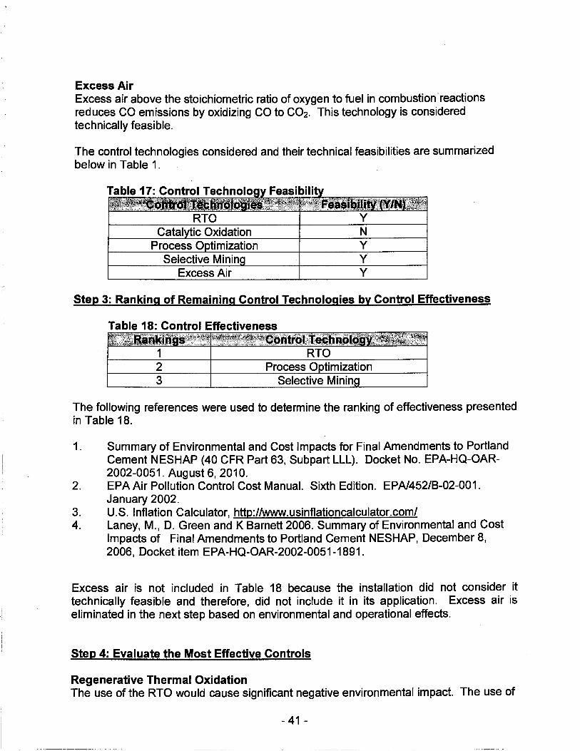
Excess Air Excess air above the stoichiometric ratio of oxygen to fuel in combustion ·reactions reduces CO emissions by oxidizing CO to CO2. This technology is considered technically feasible.
The control technologies considered and their technical feasibilities are summarized below in Table 1.
Excess Air
Step 3: Ranking of Remaining Control Technologies by Control Effectiveness
Table 18: Control Effectiveness ;:~~;!~ ~~1:~~r~r~i~1~~i(;inttftt1tJil~tl.. "''.:·
1 RTO 2 Process O timization 3 Selective Minin
The following references were used to determine the ranking of effectiveness presented in Table 18.
1. Summary of Environmental and Cost Impacts for Final Amendments to Portland Cement NESHAP (40 CFR Part 63, Subpart LLL). Docket No. EPA-HQ-OAR-2002-0051. August 6, 2010.
2. EPA Air Pollution Control Cost Manual. Sixth Edition. EPA/452/8-02-001. January 2002.
3. U.S. Inflation Calculator, http://www.usinflationcalculator.com/ 4. Laney, M., D. Green and K Barnett 2006. Summary of Environmental and Cost
Impacts of Final Amendments to Portland Cement NESHAP, December 8, 2006, Docket item EPA-HQ-OAR-2002-0051-1891.
Excess air is not included in Table 18 because the installation did not consider it technically feasible and therefore, did not include it in its application. Excess air is eliminated in the next step based on environmental and operational effects.
Step 4: Evaluate the Most Effective Controls
Regenerative Thermal Oxidation The use of the RTO would cause significant negative environmental impact. The use of
- 41 -
a stand-alone RTO system will likely result in significant oxidation of S02 to S03. The S03 emissions will have the potential to react with other stack gas constituents and produce elevated opacity. To eliminate this opacity problem, a wet lime scrubber (WLS) must be installed to decrease the S02 concentration entering the RTO. The kiln exhaust gas would need to be reheated from 135 °F to 1,800 °F for the RTO to operate properly. Natural gas would be needed as the supplemental fuel to reheat the exit stream causing more NOx emissions. Furthermore, the RTO will use a significant amount of electricity, causing additional air pollution being generated.
As for economic feasibility, Buzzi estimates that CO would be removed at a cost of $7,912.53 per ton. There is no agreed-upon value that would signify economic infeasibility. However, other BACT analysis performed around the country have generally regarded RTO as economically infeasible. There have only been two facilities that have employed RTO as control, none as a result of BACT analysis. At TXI, Midlothian, TX, an RTO system was installed to avoid PSD review and this unit has experienced significant operational difficulties which included higher than anticipated heat exchanger fouling and pressure drop, which increases afterburner fuel cost and decreases kiln capacity. At Holcim, Dundee, Ml, the plant installed an RTO to control visible emissions and odor. This unit has experienced poor heat recovery, high fuel costs, and significant maintenance problems.
Based on the significant negative environmental impact, the high cost of removal, and significant problems with previously installed RTOs, this technology is declared
ineffective as BACT control.
Selective Mining
During the review for the last PSD permit (No. 122005-005) issued to the installation, selective mining was deemed economically infeasible. For this project, the same reasoning can be used. The implementation of selective mining would require the facility to conduct extensive expulsion testing throughout the quarry in order to identify areas of elevated hydrocarbon content. Once identified, the material would have to be excavated and removed. Due to the significant vertical and lateral variability of hydrocarbons, effective mitigation of organic compound is unlikely. Furthermore, the scope of viable raw material candidates is limited by the extremely exacting requirements of raw mix chemistry. Substitution of limestone source, iron source, silica source, and red clay source were all determined to be economically infeasible.
Process Optimization There are no additional costs attributed to process optimization. Complete combustion is accomplished through careful monitoring and adjustment of fuel rates and combustion air. Process optimization will lead to lower production costs, optimization of fuel resources, and optimal combustion efficiency. Furthermore, BACT analysis performed around the country have shown that process optimization is the effective CO BACT control for a kiln at a Portland Cement facility.
- 42 -

I ._;
I
Excess Air
Cement kilns require a large amount of excess air for proper operation. Oxidizing conditions in the burning zone of the kiln are necessary for producing quality clinker, because high levels of 0 2 and low levels of CO tend to stabilize alkali and calcium sulfates. Adding excess air above the amount necessary for proper operation to either the kiln or the precalciner would cause a large increase in the NOx emissions from the kiln. Furthermore, the rate of clinker production decreases with increase in excess air, lowering the operating efficiency of the plant. Therefore, this is not considered feasible based on environmental and operational grounds.
Step 5: Select BACT
The control technology chosen based on technical, economical, and environmental feasibility is process optimization (good combustion practice). The facility suggested a BACT limit of 2.0 lb/ton on a 30-day rolling average. A review of previous BACT analysis performed around the country shows that there are only two facilities in the United States with a lower BACT limit : Universal Cement in Illinois with a BACT limit of 1.05 lb/ton on a 30 day rolling average and CEMEX, Inc. in Texas with a BACT limit of 1.38 lb/ton on a 12-month rolling average.
Buzzi Unicem USA- Festus plant cannot emit CO emissions on par with the above two facilities due to both how CO emissions are formed during the cement production process and based on the technology of the kiln currently in use at the facility. CO emissions from a cement kiln are driven by several factors such as system design/combustion technologies used, operating parameters, and raw material selection. The kiln used at Festus utilizes low NOx burners, which uses fuel to strategically generate CO within zones of the combustion chambers to chemically reduce NOx. Re-oxidation of the CO to CO2 at lower temperature releases heat but with lower NOx formation. Some residual CO is inevitable when optimizing the kiln system for lowering NOx.
Good combustion practice dictates that sufficient excess air must be used to efficiently combust the fuel but too much excess air reduces efficiency and must not be used in an effort to avoid the indiscriminate formation of NOx. Some CO formation will occur when trying to optimize the combustion process.
Organic content of the raw material being introduced into the kiln system also has an impact on CO emissions. Organic matter in the kiln feed is driven off at various concentration depending on the volatility of the organics and the temperature gradation as the feed enters the combustion zones. The volatilized organics partially combust, forming CO that is emitted with the process gases.
Due to the need to emit some CO for the above reasons, it is common, for the facility, at times to emit CO in excess of the 2.0 pounds per ton of clinker. Furthermore, both facilities with lower BACT limits have not been constructed as of the issuance date of this permit. It is unknown, at this time, whether these facilities can be compliant with
- 43 -

such a low limit. Based on these facts and that all other cement facilities in the US have CO BACT limits greater than 2.0 pounds per ton of clinker ton on a 30-day rolling average, this limit was approved for use in this permit.
FINISH MILL #3 FURNACE
Finish Mill #3 is equipped with a natural gas-fired furnace to dry the finish grinding materials. The Finish Mill #3 Furnace is used intermittently during very cold ambient conditions experienced in the winter months. The Finish Mill #3 Furnace is natural gasfired and utilizes a 35 MMBtu/hr thermal dryer, as needed, to dry the finish grinding materials (i.e., clinker and gypsum), which are processed by Finish Mill #3 to produce a product, Portland cement. The Finish Mill #3 Furnace was designed to only utilize natural gas as a fuel and has a potential throughput usage rate of 300.6 million standard cubic feet (MMscf) per year of natural gas. CO emissions from the Finish Mill #3 Furnace are emitted to the atmosphere through the Finish Mill #3 stack. The Finish Mill #3 Furnace utilizes the latest state-of-the-art combustion efficiency technology at the time of its construction in 2008.
The Finish Mill #3 Furnace PTE CO annual emission rate is 12.6 tons per year and was estimated using U.S. EPA's AP-42 Section 1.4 CO emission factor of 84 lb/MMscf, applicable for uncontrolled small (less than 100 MM Btu/hr) natural gas fired boilers. The PTE CO annual emission rate from the Finish Mill #3 Furnace represents approximately 0.4 percent of the total facility-wide PTE CO annual emissions.
Provided below is a five-step CO BACT Analysis for the Finish Mill #3 Furnace.
Step 1: Identify All Control Technologies
The first step in the BACT analysis is to identify all potential control technologies for each assessed air pollutant. Two potential control technologies were found to be applicable to the Finish Mill #3 Furnace and are as follows:
• Proper Design (Good Combustion Practices) • Catalytic Oxidation
Step 2: Eliminate Technically Infeasible Options
Because of the intermittent operation and the low annual CO emission rate of the Finish Mill #3 Furnace, post-combustion controls such as catalytic oxidation has never been demonstrated or required as CO BACT on a cement plant's Finish Mill Furnace. A review of the U.S. EPA RBLC confirms that CO post-combustion control technology has never been required to meet CO BACT for a cement plant finish mill furnace because of the inherent intermittent operation of a finish mill furnace. Additionally, use of postcombustion control technology, such as catalytic oxidation, would be expected to be prohibitively expensive. For these reasons, catalytic oxidation has been eliminated from further consideration.
- 44 -
Step 3: Rank Remaining Control Technologies by Control Effectiveness Proper Design (Good Combustion Practices) is the only remaining technically feasible control technology.
Step 4: Evaluate Most Effective Controls
Use of Proper Design (Good Combustion Practices) results in a PTE CO annual emission rate from the Finish Mill #3 Furnace of 12.6 tons per year and represents approximately 0.4 percent of the total facility-wide PTE CO annual emissions.
Step 5: Select BACT
Proper Design (Good Combustion Practices) has been determined as CO BACT for the Finish Mill #3 Furnace. The proposed CO BACT will not have any adverse environmental or energy impacts. The BACT limit is chosen to be 0.084 lb/MMBtu (84 lb/mmscf), which is within the common range for furnaces at other facilities.
Good combustion practices include the following.
• Equipment operation: • Practices relating to maintaining the appropriate stoichiometric ratio between fuel
and air, such as burner and control adjustment based on direct and/or indirect (camera) visual checks, burner and control adjustment based on continuous or periodic monitoring of 0 2 and CO, and automatic safety interlocks;
• Practices relating to insuring the appropriate quality of fuels, such as fuel quality certification from suppliers, fuel sizing specifications and checks, periodic fuel sampling and analysis;
• Practices relating to maintaining the appropriate combustion air distribution and fuel dispersion, such as adjustments based on direct and/or indirect visual observations.
• Operator Practices: • Practices relating to insuring that adequate and consistent combustion
procedures are in use, such as official documented operating procedures (updated as required for equipment or practice change), procedures for all phases of combustion including startup, shutdown, malfunction, the compilation and maintenance of operating logs;
• Maintenance Practices: • Practices relating to maintaining the combustion equipment and the combustion
monitoring and control equipment in good working order, such as the preparation of official documented maintenance procedures, updated as required for equipment or practice change, the performance of routinely scheduled evaluation, inspection, overhaul as appropriate for equipment involved, and the compilation and maintenance of logs recording compliance with all required procedures.
- 45 -
EMERGENCY GENERA TOR
The Emergency Generator is an 815 horsepower (hp) diesel-fired engine which is operated for routine maintenance and testing, or in the event of a power outage at the Plant. As a result, the Emergency Generator is operated intermittently during the year and is limited to operate no more than 500 hours per year. The PTE CO emissions from the Emergency Generator were estimated using the manufacturer guaranteed CO emission rate of 1.06E-3 lb/hp-hr, which is equivalent to 0.48 g/hp-hr. Given the Emergency Generator's limited hours of operation per year, the annual PTE CO emission was estimated to be 0.22 tons per year which represents approximately 0.01 percent of the total facility-wide PTE CO emissions.
Provided below is a five-step CO BACT Analysis for the Emergency Generator.
Step 1: Identify all control technologies
The first step in the BACT analysis is to identify all potential control technologies for each assessed air pollutant. Two potential control technologies were found to be applicable to the Emergency Generator and are as follows:
• Proper Design (Good Combustion Practices) • Catalytic Oxidation
Step 2: Eliminate technically infeasible options
Because of the intermittent hours of operation (i.e., maximum of 500 hours/year) and corresponding low CO annual emissions of the Emergency Generator, post-combustion control technology such as catalytic oxidation has never been demonstrated or required as CO BACT for a cement plant's Emergency Generator. A review of the U.S. EPA RACT/BACT/LAER Clearinghouse (RBLC) confirms that post-combustion control technology has not been required to be installed as CO BACT for any cement plant Emergency Generator because of the inherent intermittent operation of the Emergency Generator. Additionally, use of post-combustion control technology, such as catalytic oxidation, would be expected to be prohibitively expensive. For these reasons, catalytic oxidation has been eliminated from further consideration.
Step 3: Rank remaining control technologies by control effectiveness
Proper Design (Good Combustion Practices) is the only remaining technically feasible control technology.
Step 4: Evaluate most effective controls
Use of Proper Design (Good Combustion Practices) results in a PTE CO emission rate from the Emergency Generator of 0.22 tons per year, which represents approximately 0.01 percent of the total facility-wide PTE annual CO emissions.
-46 -
Step 5: Select BACT
Proper Design (Good Combustion Practices) has been determined to be CO BACT for the Emergency Generator. The proposed CO BACT will not have any adverse environmental or energy impacts. The BACT emission limit is 0.48 g/hp-hr, which is less than all but one of the BACT emission limits given to other facilities.
GHG BACT ANALYSIS FOR THE PH/PC KILN
Step 1: GHG Control Technologies for PH/PC Kiln
The following BACT options were considered
Table 19: GHG Control Technolo ies
Energy Efficiency Improvement
Heat Recove for Power Fuel Substitution
Product Composition
Carbon Capture/Removal and Storage
Ener Use of Fluxes and Mineralizers
Co eneration Use of Alternative Fuels (e.g. Natural
Gas, Whole Tires, Biofuels, etc. Use of Supplemental Raw Materials
and Cement Additives Carbon Se uestration
Calera Process 0 -Combustion
Post-combustion Solvent Capture and Stri in
Post-combustion Membranes Su erheated Calcium Oxide
Step 2: Eliminate the Technically Infeasible Options
PH/PC Kiln Process The PH/PC kiln system is the major consumer of both the electrical and thermal energy in a Portland cement plant. Clinker production in the kiln generally accounts for over 95% of the energy use at a Portland cement facility equipped with an in-line raw mill. Energy efficiency improvements are the result of combined effects of shifting from the energy inefficient wet process kiln system technology to the most efficient dry process kiln system technology. Of the dry process kiln system technologies: the long dry kiln system, the PH kiln system, and the PH/PC kiln system, the PH/PC kiln system is the most energy efficient. Buzzi is already utilizing the PH/PC kiln system. The energy efficiency of PH/PC kiln is achieved through the use of multiple pre-heater (PH) cyclones and one precalciner (PC) vessel. Buzzi utilizes five (5) stages of the preheat process. In the pre-heat stages, the kiln feed is pre-heated using the rising hot kiln
- 47 -
exhaust gases which flow counter-currently to the kiln feed which is falling through the PH cyclones. This reduces the processing time. The gas that exit the PH tower are further utilized for heat recovery as the kiln exhaust gases are used to dry the raw materials in the in-line raw mill prior to the gases release to the atmosphere through the kiln stack.
Since the installation is already using the PH/PC design, this technology is considered technically feasible.
Kiln Seal Management Program Kilns have seals at their inlet and outlet to reduce heat "losses" due to air infiltration. Leakage increases fuel consumption due to the cooling effect of the air, reducing energy efficiency of the kiln, and increasing fuel requirements. Various types of seals are commercially available and a kiln seal management program is considered to be technically feasible.
Refractory Selection (Kiln Insulation) A cement kiln has a steel shell which is lined in the combustion zone with heat resistant refractory to insulate the shell. The lining reduces the heat loss which results in increase energy efficiency. The lining also protects the shell from the corrosive nature of the raw materials. Refractory is made of materials such as bricks or cast refractory concrete. Having a high temperature insulating refractory reduces kiln fuel usage. The plant will utilize refractory material to line and insulate the plant kiln. This technology is considered to be technically feasible.
Energy Recovery from the Clinker Cooler In the cement production process, clinker produced by the cement kiln is sent to the clinker cooler for rapid air-cooling before it is sent to the finish mill. In this process, clinker is cooled from about 2,000 °F to 200 °F. The cooling process is commonly utilized to reduce energy consumption by using heat from the clinker to pre-heat combustion air or dry fuel prior to introduction to the kiln. In the clinker cooler, ambient air is blown through the blended material to enhance the cooling process. For the plant, the clinker cooler exhaust air is vented to the solid fuel mill and used to dry the solid fuel, which results in energy recovery since a thermal dryer is not required as part of solid fuel mill operations. This control technology is considered to be technically feasible.
Use of Fluxes and Mineralizers The use of fluxes and mineralizers has been studied extensively in the cement industry. It is understood that fluxes and mineralizers can be added to the cement kiln raw feed to lower the peak temperature required to form cement clinker by 100 °F to 200 °F. This can correspondingly reduce fuel consumption, and therefore, have the potential to reduce GHG emissions. Calcium fluoride (Caf2), although cost prohibitive, has been used as a fluxing agent in the cement clinkering process. Furthermore, process spent pot liners (SPLs) obtained from primary aluminum smelters contain sodium fluoride (NaF) and can serve as a fluxing agent. Only a small amount of fluxing agents can be used and maintain the quality standards for setting times of the cement. Also, due to
- 48 -
the sodium content of fluxing agents in the SPL, usage must be limited to remain below the amount of sodium allowed in cement. In addition, there is very limited availability of SPL. This method is considered technically infeasible.
Cogeneration Cogeneration involves the recovery of heat from the exhaust of the kiln for power generation. However, Buzzi uses a five-stage PH/PC kiln system with in-line raw mill. The kiln system exhaust gas will be used to pre-heat the raw material and as a result, there would be little heat left to support cogeneration. This method is considered technically infeasible.
Fuel Substitution GHG emissions from fossil fuel burning in the PH/PC kiln system could potentially be reduced by using a relatively cleaner burning fuel such as oil, whole tires, natural gas, or biomass. The use of alternative fuels, therefore, is considered to be technically feasible.
Product Composition Product composition would be altered with the use of supplemental additive materials. The cement manufacturing process produces two products: clinker (intermediate product) and cement (final product). Supplemental additives can be classified as two types: cementitious and pozzolan material. Cementitious materials have properties similar to cement and include, but are not limited to, blast furnace slag, iron slag, and foundry sand. Pozzolan material exhibits cementitious properties when mixed with calcium hydroxide, and include, but are not limited to diatomite, calcined clay, calcined shale, metakaolin, silica fume, and coal combustion fly ash.
Supplemental additive material would potentially replace a portion of the limestone contained in the raw meal to the plant in-line raw mill. Theoretically, a lesser amount of limestone would be required to produce the same amount of clinker when using supplemental additives. As a result, GHG emissions associated with the calcination process of limestone, which occurs in the kiln system, would be reduced.
-----
The chemical composition of the supplemental additives would limit the amount of limestone that can be replaced. Any excess silica, magnesium, aluminum, VOC, or other trace elements contained in the supplemental additives represents a potential concern due to the precise raw material formula, which always has to be met to assure that clinker quality meets established applicable cement quality standards. Supplemental additives can also be used to replace a portion of the clinker used by the finish mills to produce the final product. GHG emissions would decrease due to the less amount of fuel used by the PH/PC kiln system and the lesser amount of limestone that would need to be used.
The use of supplemental additive material to replace either the limestone or clinker is dependent on the following:
• The properties of the supplemental additives. • The availability of the supplemental additives.
- 49 -
• The cement quality standards which need to be met for the blended cement final product.
• The acceptance of the blended cement final product in the cement marketplace. • The intended application of the blended cement final product.
This control method is considered not technically feasible due to lack of availability for supplemental additive materials that have consistent properties.
Carbon Capture/Removal/Storage The following potential carbon capture, removal, and storage technologies can be considered for GHG emissions control.
Post Combustion Carbon Capture and Storage (CCS) CCS involves the separation and capture of CO2 from kiln exhaust gases, pressurization of the captured CO2, transportation of the CO2 via pipeline, and injection and long-term geologic storage of the captured CO2. CCS relies on the downstream separation of CO2 using different chemical or physical processes as given below.
• Chemical absorption (amine scrubbing, chilled ammonia) • Membrane technologies • Adsorption technologies • Mineralization • Calcium looping
Buzzi Unicem USA - Festus Plant is located in a geographic area that does not have access to an existing CO2 pipeline to transport the CO2 emissions from the plant. However, this is not a technical consideration, but an economic one. It is feasible that a piping system can be constructed. Therefore, this technology is considered technically feasible during this step.
Calera Process The Calera Process involves the capture of CO2 by chemically converting CO2 to carbonates. The kiln exhaust gases are passed through a wet scrubber with high pH water containing calcium, magnesium, sodium, and chloride as the scrubbing liquid. CO2 in the exhaust gas is absorbed in the water and is converted to carbonic acid. The high pH of the water results in the dissociation of the carbonic acid, which reacts with the calcium and magnesium ions in the water to form carbonate minerals. The minerals can be precipitated from the solution for use in blended cement or other building materials. The scrubbing water can be treated to remove sodium chloride and reused as potable water. This process is still in the research stages and has not been demonstrated in practice at any facilities. Therefore, this process is considered technically infeasible.
Oxy-Combustion Oxy-Combustion is a process in which fuel (e.g. coal) is burned in the presence of nearly pure oxygen instead of air. Nitrogen from the combustion air is removed using an air separation unit prior to feeding the combustion air to the kiln. Under these conditions, the exhaust gases are rich in CO2 (up to 80%). The CO2 from the exhaust
- 50 -
gases is discharged to a CO2 separation, purification, and compression facility. This technology is still in the research stages and has not been demonstrated in any facility. Furthermore, the paper "Available and Emergency Technologies for Reducing Greenhouse Gas Emissions From the Portland Cement Industry," EPA, October 2010, lists numerous technical issues related to using oxy-combustion. These include, but are not limited to, the following.
• Flame Temperatures and Dilution: Flame temperatures in excess of 3,500 °C can be achieved using oxy-combustion, which is too hot for proper operation of a cement kiln. A portion of the flue gases must be recycled back to the combustion zone to provide the necessary dilution.
• Heat Transfer Characteristics: Changing the atmosphere within the combustion chamber will have significant effect on the heat transfer characteristics.
• Feed Lifting: Nitrogen ballast in the exhaust gases from the kiln plays an important role in lifting the feed between the cyclone stages in the suspension preheater. CO2 is a denser gas than nitrogen and should be more effective in this feed lifting role.
• Wear and Tear: Due to higher temperatures, kiln wall deterioration may increase, leading to more frequent replacement of the kiln lining.
• Process Chemistry: Research is still on-going to determine whether the clinker formation in a different atmosphere will still generate a useful product.
• Air Dilution: Excessive air in-leaks will result in contamination of the CO2-rich exhaust gas. These contaminates will require removal, which will increase costs.
• Flue Gas Cleanup: Depending on the final storage location of the CO2, the gas will require some clean-up to remove water vapor, nitrogen, argon, NOx, and SOx.
• Air Separation Unit (ASU): An ASU will be required to deliver oxygen to the process, which will increase electrical demand.
• Reducing Conditions: The oxygen concentration in the clinker production process must be maintained at greater than 2 percent by weight.
For these reasons, Oxy-combustion is not considered technically feasible.
Post-Combustion Membrane This method uses permeable or semi-permeable membranes to separate CO2 from the flue gas. The separated CO2 can then be compressed and sent to a CO2 storage site for sequestration. This technology is still in the research stages and not commercially available. This technology is considered technically infeasible.
Superheated Calcium Oxide (CaO) In this process, calcination and combustion reactions are separated in independent
. chambers so that exhaust gases from the calcination process are rich in CO2. This is achieved by providing heat to the calciner using circulation of superheated Cao particles between a fluidized bed combustor and a fluidized bed calciner. The CO2 rich exhaust from the calciner can then be collected, compressed, and sent to a CO2 storage site for sequestration. This technology is currently in the research stage and has not been demonstrated in practice. Therefore, it is considered technically infeasible.
- 51 -
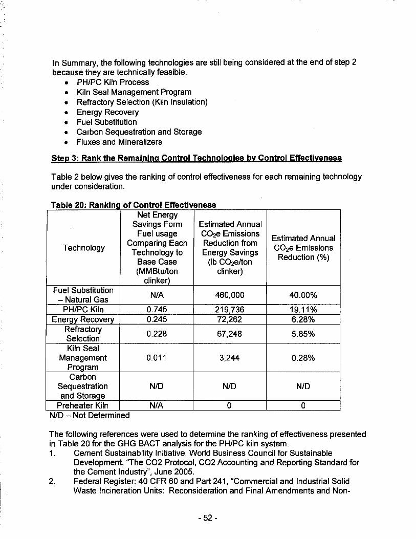
In Summary, the following technologies are still being considered at the end of step 2 because they are technically feasible.
• PH/PC Kiln Process • Kiln Seal Management Program • Refractory Selection (Kiln Insulation) • Energy Recovery • Fuel Substitution • Carbon Sequestration and Storage • Fluxes and Mineralizers
Step 3: Rank the Remaining Control Technologies by Control Effectiveness
Table 2 below gives the ranking of control effectiveness for each remaining technology under consideration.
T bl 20 R k" f C t I Eff f a e . an lnl;l 0 on ro ec 1veness . Net Energy
Savings Form Estimated Annual Fuel usage C02e Emissions
Estimated Annual Technology
Comparing Each Reduction from C02e Emissions Technology to Energy Savings
Base Case (lb C02e/ton Reduction(%)
(MM Btu/ton clinker) clinker)
Fuel Substitution N/A 460,000 40.00%
- Natural Gas PH/PC Kiln 0.745 219,736 19.11%
Energy Recovery 0.245 72,262 6.28% Refractory
0.228 67,248 5.85% Selection Kiln Seal
Management 0.011 3,244 0.28% Program Carbon
Sequestration N/D N/D N/D and Storage
Preheater Kiln N/A 0 0 N/D - Not Determined
The following references were used to determine the ranking of effectiveness presented in Table 20 for the GHG BACT analysis for the PH/PC kiln system. 1. Cement Sustainability Initiative, World Business Council for Sustainable
Development, "The CO2 Protocol, CO2 Accounting and Reporting Standard for the Cement Industry", June 2005.
2. Federal Register: 40 CFR 60 and Part 241, "Commercial and Industrial Solid Waste Incineration Units: Reconsideration and Final Amendments and Non-
- 52 -
Hazardous Secondary Materials That Are Solid Waste; Final Rule", February 7, 2013.
3. U.S. EPA, Office of Air and Radiation, "Available and Emerging Technologies for Reducing Greenhouse Gas Emissions from the Portland Cement Industry", October 2010.
4. U.S. EPA, Office of Air Quality Planning and Standards, "New Source Review Workshop Manual", Draft October 1990.
5. Cement Sustainability Initiative, World Business Council for Sustainable Development, "Development of State of the Art-Techniques in Cement Manufacturing: Trying to Look Ahead", (CSI/ECRA- Technology Papers), Section 3.9, June 2009.
6. Cement Sustainability Initiative, World Business Council for Sustainable Development, "Development of State of the Art-Techniques in Cement Manufacturing: Trying to Look Ahead", (CSI/ECRA- Technology Papers), Section 2.4.3, June 2009.
7. Website: http://www.nrmca.org/research/CIF%2006-4%20Tech%20Talk.pdf, "The Impact of Fly Ash on Air Entrained Concrete", HPC Bridge Views Issue No. 32, March/April 2004.
8. Cement Sustainability Initiative, World Business Council for Sustainable Development, "Development of State of the Art-Techniques in Cement Manufacturing: Trying to Look Ahead", (CSI/ECRA - Technology Papers), Section 2.1.3, June 2009.
9. U.S. EPA, Office of Air Quality Planning and Standards, Alternative Control Techniques Document Update - NOx Emissions from New Cement Kilns, EPA-453/R-07-006, November 2007.
10. U.S. Energy Administration, Florida, Website: http://www.eia.gov/state/data.cfm?sid=FL .
11. Holcim (US) Inc., "Permit To Construct Application, Hagerstown Plant", Page 6-19, July 2013.
Step 4: Evaluate Most Effective Controls Taking Into Account Cost and Environmental Factors
Alternative Fuels The facility plans to use alternative fuels but only during the periods of start-up and shut-down. During normal operations, there are environmental and economic concerns. The use of natural gas as fuel would significantly increase NOx emissions. Given the role of NOx emissions in ozone, fine particulate matter, and acid rain formations, this increase in NOx emissions would have significant adverse environmental impact. According to the U.S. Energy Information Administration, the cost of natural gas is $6.26 per thousand cubic feet, which results in $19.74 per tons of clinker. The cost of petroleum coke is $39.47 per ton, which comes to $4.83 per tons of clinker. The natural gas is currently over four times more costly than petroleum coke. Furthermore, it is estimated that at full production, the cost of natural gas per year would be $49,353,840 as opposed to $12,077,820 for petroleum coke. This is considered economically
- 53 -
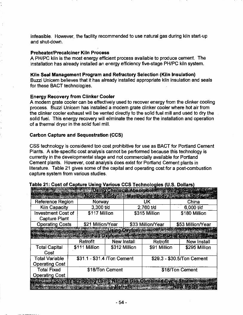
infeasible. However, the facility recommended to use natural gas during kiln start-up and shut-down.
Preheater/Precalciner Kiln Process A PH/PC kiln is the' most energy efficient process available to produce cement. The installation has already installed an energy efficiency five-stage PH/PC kiln system.
Kiln Seal Management Program and Refractory Selection (Kiln Insulation) Buzzi Unicem believes that it has already installed appropriate kiln insulation and seals for these BACT technologies.
Energy Recovery from Clinker Cooler A modern grate cooler can be effectively used to recover energy from the clinker cooling process. Buzzi Unicem has installed a modern grate clinker cooler where hot air from the clinker cooler exhaust will be vented directly to the solid fuel mill and used to dry the solid fuel. This energy recovery will eliminate the need for the installation and operation of a thermal dryer in the solid fuel mill.
Carbon Capture and Sequestration (CCS)
CSS technology is considered too cost prohibitive for use as BACT for Portland Cement Plants. A site-specific cost analysis cannot be performed because this technology is currently in the developmental stage and not commercially available for Portland Cement plants. However, cost analysis does exist for Portland Cement plants in literature. Table 21 gives some of the capital and operating cost for a post-combustion capture system from various studies.
Total Capital Cost
Total Variable 0 eratin Cost
Total Fixed
UK China 3,300 t/d 2,760 t/d 6,000 t/d
$117 Million $315 Million $180 Million
Retrofit New Install Retrofit New Install $111 Million $312 Million $91 Million $295 Million
$31.1 - $31.4 /Ton Cement $29.3 - $30.5/Ton Cement
$18/T on Cement $18/Ton Cement
- 54 -
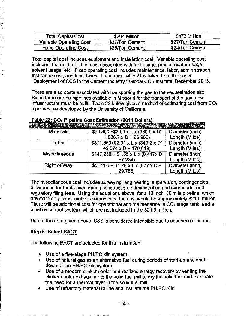
-:-: ,.·1 '."~ I
Total Capital Cost $264 Million $472 Million Variable OperatinQ Cost $37 rr on Cement $27ffon Cement
Fixed OperatinQ Cost $25ff on Cement $24ffon Cement
Total capital cost includes equipment and installation cost. Variable operating cost includes, but not limited to, cost associated with fuel usage, process water usage, solvent usage, etc. Fixed operating cost includes maintenance, labor, administration, insurance cost, and local taxes. Data from Table 21 is taken from the paper "Deployment of CCS in the Cement Industry," Global CCS Institute, December 2013.
There are also costs associated with transporting the gas to the sequestration site. Since there are no pipelines available in Missouri for the transport of the gas, new infrastructure must be built. Table 22 below gives a method of estimating cost from CO2 pipelines, as developed by the University of California.
Labor
Miscellaneous
Right of Way
$70,350 +$2.01 X L X (330.5 X D + 686.7 x D + 26,960
$371,850+$2.01 X L X (343.2 X D +2,074 x D + 170,013
$147,250 + $1.55 x L x (8,417x D +7,234
$51,200 + $1.28 XL X (577 X D + 29,788
Diameter (inch) Len th Miles Diameter (inch) Len th Miles Diameter (inch) Len th Miles Diameter (inch) Len th Miles
The miscellaneous cost includes surveying, engineering, supervision, contingencies, allowances for funds used during construction, administration and overheads, and regulatory filing fees. Using the equations above, for a 12 inch, 30 mile pipeline, which are extremely conservative assumptions, the cost would be approximately $21.9 million. There will be additional cost for operational and maintenance, a CO2 surge tank, and a pipeline control system, which are not included in the $21.9 million.
Due to the data given above, CSS is considered infeasible due to economic reasons.
Step 5: Select BACT
The following BACT are selected for this installation.
• Use of a five-stage PH/PC kiln system. • Use of natural gas as an alternative fuel during periods of start-up and shut
down of the PH/PC kiln system. • Use of a modern clinker cooler and realized energy recovery by venting the
clinker cooler exhaust air to the solid fuel mill to dry the solid fuel and eliminate the need for a thermal dryer in the solid fuel mill.
• Use of refractory material to line and insulate the PH/PC Kiln.
- 55 -

• Use of a kiln seal management program to reduce heat loss due to air-infiltration
The BACT emissions limit for C02e is 0.95 lb/ton of clinker, based on a 12-month rolling average. This is a common value for BACT limits from other Portland cement facilities using the PH/PC kiln system. Furthermore, the facility installed a CO2 CEMS in 2010 and the four year average after the CEMS was installed is 0.95 lb/ton of clinker, based on CO2 emissions from CEMS data and CH4 and N20 emissions calculated per 40 CFR 98, Subpart A and C. Lastly, the cement plant with BACT limit for C02e less than 0.95 lb/ton have not been constructed yet and therefore, have not demonstrated that these lower limits can be met on a consistent basis during normal operations.
FINISH MILL #3 FURNACE
Finish Mill #3 is equipped with a natural gas-fired furnace to dry the finish grinding materials. This furnace is used intermittently, but especially during very cold ambient conditions experienced during the winter season. The natural gas-fired furnace utilizes a 35 MMBtu/hr thermal dryer, as needed, to dry the finish grinding materials (i.e., clinker and gypsum), which is processed by Finish Mill #3 into a product, Portland cement. The Finish Mill #3 Furnace utilizes natural gas as a fuel and has a potential throughput of 300.6 million standard cubic feet (MMscf) per year of natural gas. C02e emissions from the Finish Mill #3 Furnace are emitted to the atmosphere through the Finish Mill #3 stack.
The Finish Mill #3 Furnace PTE C02e emissions are 18,057 tons per year and were estimated using 40 CFR 98 Subpart C GHG emission factors (11/9/2013) and Subpart A, Table A-1 (12/11/14) GHG global warming potentials. The PTE annual C02e emission rate of 18,057 tons per year from the Finish Mill #3 Furnace represents approximately 0. 75 percent of the total facility-wide PTE C02e annual emissions.
Provided below is a five-step GHG BACT Analysis for the Finish Mill #3 Furnace.
Step 1: Identify All Control Technologies
The first step in the BACT analysis is to identify all potential control technologies for each assessed air pollutant. Two potential control technologies were found to be applicable to the Finish Mill #3 Furnace and are as follows:
• Use of Both Diesel Fuel and Good Combustion Practices • Use of Both Natural Gas Fuel and Good Combustion Practices
Step 2: Eliminate Technically Infeasible Options
Both options listed in Step 1 are considered technically feasible for the Finish Mill #3 Furnace.
- 56 -
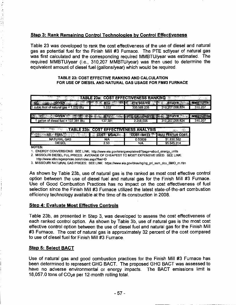
.... .. '
Step 3: Rank Remaining Control Technologies by Control Effectiveness
Table 23 was developed to rank the cost effectiveness of the use of diesel and· natural gas as potential fuel for the Finish Mill #3 Furnace. The PTE set/year of natural gas was first calculated and the corresponding required MMBTU/year was estimated. The required MMBTU/year (i.e., 310,207 MMBTU/year) was then used to determine the equivalent amount.of diesel fuel (gallons/year) which would be required.
TABLE 23: COST EFFECTIVE RANKING AND CALCULATION FOR USE OF DIESEL AND NATURAL GAS USAGE FOR FM#3 FURNACE
TABLE 23a: COST EFFECTIVENESS RANKING lr"{i;fp'.f_·.·i$Jn:WlfJl~ ;1:1~,1%l~l11~~l}J}ll:'.~ iiNf1STtiW'~'l1
2,258,006 310,207,058,824 310,207
.. · ,· ·· TABLE 23b: COST EFFECTIVENESS ANALYSIS :~t~l;j\i'.'.,;'2:'~~,,~,~\f;'' ·-··- .:.' ·,;,,:, ::·;:~::.Ji:::·;;·' • ';~\;~Q$Jf''.·l!~AP~~'..: '}{::qQ§J}.:$l.FJ~;2,z':~:, 's(ilJ ~i:s'.tU$~·c0$'t,
NATURAL GAS N/A 0.00609 $1,830,582 DIESEL 2.50 N/A $5,645,014
NOTES: 1. ENERGY CONVERSIONS: SEE LINK: http://www.eia.gov/energyexplained/?page=about_energy_units 2. MISSOURI DIESEL FUL PRICES: AVERAGE OF CHEAPEST TO MOST EXPENSIVE USED. SEE LINK:
http://www.stlouisgasprices.com/index.aspx?fuel=D 3. MISSOURI NATURAL GAS PRICES: SEE LINK: https://www.eia.gov/dnav/ng/ng_pri_sum_dcu_SMO_m.htm
As shown by Table 23b, use of natural gas is the ranked as most cost effective control option between the use of diesel fuel and natural gas for the Finish Mill #3 Furnace. Use of Good Combustion Practices has no impact on the cost effectiveness of fuel selection since the Finish Mill #3 Furnace utilized the latest state-of-the-art combustion efficiency technology available at the time of its construction in 2008.
Step 4: Evaluate Most Effective Controls
Table 23b, as presented in Step 3, was developed to assess the cost effectiveness of each ranked control option. As shown by Table 3b, use of natural gas is the most cost effective control option between the use of diesel fuel and natural gas for the Finish Mill #3 Furnace. The cost of natural gas is approximately 32 percent of the cost compared to use of diesel fuel for Finish Mill #3 Furnace.
Step 5: Select BACT
Use of natural gas and good combustion practices for the Finish Mill #3 Furnace has been determined to represent GHG BACT. The proposed GHG BACT was assessed to have no adverse environmental or energy impacts. The BACT emissions limit is 18,057.0 tons of C02e per 12-month rolling total.
- 57 -
EMERGENCY GENERA TOR (9-M-22)
The Emergency Generator is an 815 horsepower (hp) diesel-fired engine which is only operated for routine maintenance and testing, or in the event of a power outage. As a result, the Emergency Generator is operated intermittently during the year and limited to operate no more than 500 hours per year. The PTE GHG (as C02e) emissions from the Emergency Generator were estimated using 40 CFR 98 Subpart C GHG emission factors (11/9/2013) and Subpart A Table A-1 (12/11/14) global warming potentials. Based on the Emergency Generator being limited to a maximum of 500 hours of operation per year, the PTE GHG annual emission rate from the Emergency Generator is estimated to be 241 tons C02e per year, which represents approximately 0.01 percent of the total facility-wide PTE GHG annual emissions.
Provided below is a five-step GHG BACT Analysis for the Emergency Generator.
Step 1: Identify All Control Technologies The first step in the BACT analysis is to identify all potential control technologies for each assessed air pollutant. Two potential control technologies were found to be applicable to the Emergency Generator and are as follows:
• Use of Both Diesel Fuel and Good Combustion Practices • Use of Both Natural Gas Fuel and Good Combustion Practices
Step 2: Eliminate Technically Infeasible Options
A natural gas-fired Emergency Generator engine would be expected to emit less GHG (i.e., C02e) than a diesel-fired Emergency Generator engine. However, the Emergency Generator engine is intended for use only in the event of a plant-wide power outage, which usually results in the interruption of the supply of natural gas. Therefore, natural gas is not considered to be technically feasible for use as a fuel for the 815 hp Emergency Generator engine. An onsite diesel fuel tank is the only uninterruptible fuel supply available for this type of Emergency Generator engine.
Step 3: Rank Remaining Control Technologies by Control Effectiveness
Use of both diesel fuel and good combustion practices for the Emergency Generator is the only remaining technically feasible control technology.
Step 4: Evaluate Most Effective Controls
Use of both diesel fuel and good combustion practices for the Emergency Generator results in a PTE C02e annual emission rate from the Emergency Generator of 241 tons per year, which represents approximately 0.01 percent of the total facility-wide PTE C02e annual emissions.
- 58 -

Step 5: Select BACT
Use of both diesel fuel and good combustion practices for the Emergency Generator has been determined to represent GHG BACT. The proposed GHG BACT was assessed to have no adverse environmental or energy impacts. The BACT emissions limit is 241.0 tons of C02e per year based on a 12-month rolling total.
STAFF RECOMMENDATION
On the basis of this review conducted in accordance with Section (8), Missouri State Rule 10 CSR 10-6.060, Construction Permits Required, it is recommended that this permit be granted with special conditions.
PERMIT DOCUMENTS
The following documents are incorporated by reference into this permit:
• The Application for Authority to Construct form, dated February 27, 2015, received March 3, 2015, designating River Cement Company as the owner and operator of the installation.
• E-mail communications between Missouri Air Pollution Control Program and Buzzi Unicem USA - Festus Plant.
Other documents relied upon during technical review.
• Baseline Actual Inventory 2014-2015 and Potential Emissions Inventory spreadsheets submitted by Buzzi Unicem USA - Festus Plant.
• "Technical Background Document on Control of Fugitive Dust at Cement Manufacturing Facilities, Draft," USEPA, March 20, 1998.
• 2016-07-08 BUU List of Inventory Changes Since July 2015, Submitted 7-19-2016 byBUU
• 'WRAP Fugitive Dust Handbook," Countess Environmental, September 7, 2006. • Bulk Material Handling Table from TCEQ • "Ambient Air Quality Impact Analysis (AAQIA) for Buzzi Unicem USA - Fests Plant,
April 7, 2016. • Drafts permits sent by Missouri Air Pollution Control Program to Buzzi Unicem USA
- Festus Plant and the installation's response comments to the drafts. • EPA RACT/BACT/LAER Clearinghouse (RBCL) https://cfpub.epa.gov/rblc/ • EPA AP-42, Fifth Edition, "Compilation of Air Pollutant Emission Factors, Volume 1:
stationary Point and Area Sources." • "Available and Emerging Technologies for Reducing Greenhouse Gas Emissions
from The Portland Cement Industry," USE PA, October, 2010.
- 59 -

•..
Appendix A
~~1~~r~tfftiW;l~-~i:~JE?I~{~Jt{l~~~1r~rwtr!!,tt~t~:1}\tJ;~1f\J1~,~{;1rrrn:~w1E?~---- ,;-~ ·:~ [-·-,w~,,, ~ fl~J'J~· --:,.·,c;:·>'"C:·,~'..'\. .,~_:'.).• .c1<,:ill'.11-"""''"'''*j~~-,l!!:c,;'i-.!icc,~°'-·"'"'",;•,.-~,,,:-., ,,,~,. ,: ~ ,l 't12l',f';''f.""1';;'ff"''"'"'fW·" ·,'t.<' ~~j;j_,:, =:t1.-1+J;g~j~~f!:~;~~ ~~·jt~~ g1~:, .. ·Jt,. ~it:i:i!~~~~" ;-<;/,' :~~E-~.-~"~t_[~~L,.\).k_ :~~>;:-~f 3,.i~~~ 1 ~~,~~=
1~,L.;'
1-Q-03 Loading Haul Trucks 3,330,391 1-Q-04A South Haul Road To Crusher 3,330,391 1-Q-04C North Haul Road To Crusher 0 1-Q-05 Limestone Storage Piles 3,330,391 1-Q-06 Sandstone Storage Pile 14,255
Haul Road(Paved): Clay; Entrance To 425,438
1-Q-07A Storage Pile Haul Road(Unpaved): Clay; Entrance To
425,438 1-Q-078 Storage Pile 1-Q-08 Clay And Substitute Storage Pile 425,438 1-Q-09 Unloading At Primary Crusher 3,330,391
1-Q-09K Clinker Unloading At Primary Crusher 200,000 1-Q-10 Primary Crusher (201010.01) 3,330,391
1-Q-10K Primary Crusher - Clinker 200,000 Haul Road(Paved)-Purchased Sand &
186,420 1-Q-11A Raw Mat-Pile
Haul Road(Unpaved)-Purchased Sand & 186,420
1-Q-118 Raw Mat Pile Haul Road(Unpaved) : Iron Ore Barge To
125,775 1-Q-11C Pile
Haul Road (Unpaved): Bottom Ash; Entry-92,290
1-Q-11 D Pile 1-Q-11 E Haul Road (Paved) Bottom Ash Entry Pile 92,290 1-Q-11 F Haul Road (Paved) To Fly Ash Silo 39,020 1-Q-12 Sand Storage Pile 186,420 1-Q-13 Bottom Ash Storage Pile 92,290 1-Q-14 Iron Ore Storage Pile 125,775 1-Q-15 Additives Crusher And Conveying 829,923
Additives Conveying To Raw Mill Feed 829,923
1-Q-16 Bins 1-Q-17 Additives Hopper 829,923 1-Q-18 Discharge To Clay Storage Dome 361,335
Tp:Primary Crusher Surge Bin Discharge-3,330,391
2-R-01 Belt 201040.05 2-R-01 K Tp: Primary Surge Bin Discharge- Belt
200,000 201040.05 Clinker
2-R-02 Belts 201040.05&202070 Discharge In
3,330,391 Surge Bin;202070 To 202090
2-R-02K Belts 201040.05 & 202070 Into Surge Bin;
200,000 202070 To 202090 Clinker
2-R-03A Surge Bin Feeders 3,330,391 2-R-03AK Surge Bin Feeders - Clinker 200,000
- 60 -
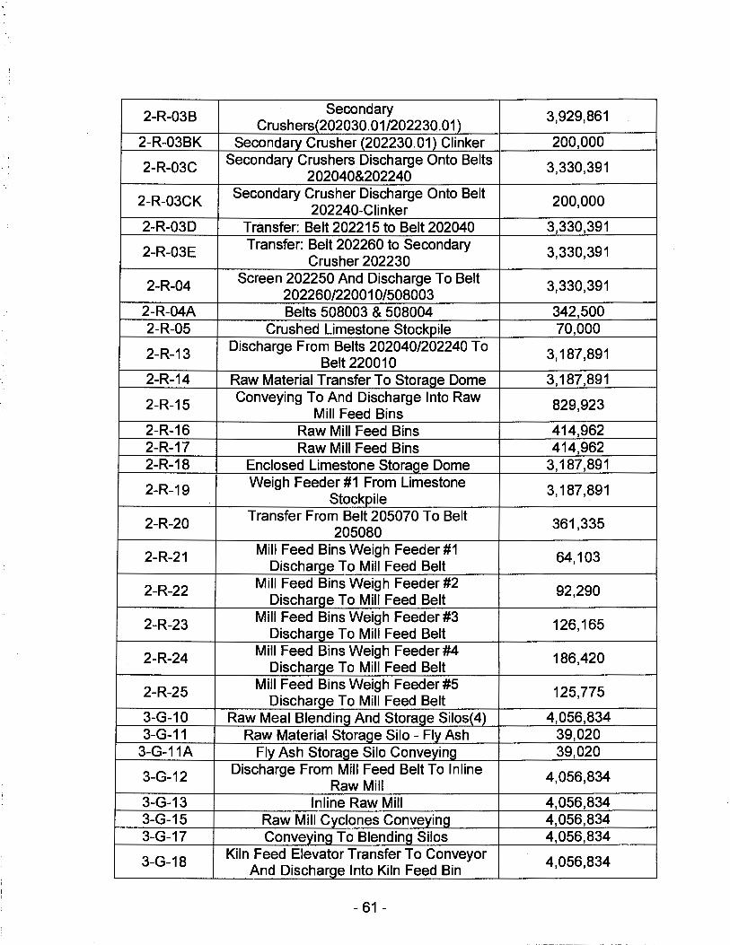
2-R-03B Secondary 3,929,861 Crushers(202030.01/202230.01)
2-R-03BK Secondary Crusher (202230.01) Clinker 200,000
2-R-03C Secondary Crushers Discharge Onto Belts 3,330,391 202040&202240
2-R-03CK Secondary Crusher Discharge Onto Belt 200,000 202240-Clinker
2-R-03D Transfer: Belt 202215 to Belt 202040 3,330,391
2-R-03E Transfer: Belt 202260 to Secondary 3,330,391 Crusher 202230
2-R-04 Screen 202250 And Discharge To Belt 3,330,391 202260/220010/508003
2-R-04A Belts 508003 & 508004 342,500 2-R-05 Crushed Limestone Stockpile 70,000
2-R-13 Discharge From Belts 202040/202240 To 3,187,891 Belt 220010
2-R-14 Raw Material Transfer To Storage Dome 3,187,891
2-R-15 Conveying To And Discharge Into Raw 829,923 Mill Feed Bins
2-R-16 Raw Mill Feed Bins 414,962 2-R-17 Raw Mill Feed Bins 414,962 2-R-18 Enclosed Limestone StoraQe Dome 3,187,891
2-R-19 Weigh Feeder #1 From Limestone 3,187,891 Stockpile
2-R-20 Transfer From Belt 205070 To Belt 361,335 205080
2-R-21 Mill Feed Bins Weigh Feeder #1 64,103 Discharge To Mill Feed Belt
2-R-22 Mill Feed Bins Weigh Feeder #2 92,290 Discharge To Mill Feed Belt
2-R-23 Mill Feed Bins Weigh Feeder #3 126,165 Discharge To Mill Feed Belt
2-R-24 Mill Feed Bins Weigh Feeder #4 186,420 Discharge To Mill Feed Belt
2-R-25 Mill Feed Bins Weigh Feeder #5 125,775 Discharge To Mill Feed Belt
3-G-10 Raw Meal Blending And Storage Silos(4) 4,056,834 3-G-11 Raw Material Storage Silo - Fly Ash 39,020
3-G-11A Fly Ash Storage Silo Conveying 39,020
3-G-12 Discharge From Mill Feed Belt To lnline 4,056,834 Raw Mill
3-G-13 lnline Raw Mill 4,056,834 3-G-15 Raw Mill Cyclones Conveying 4,056,834 3-G-17 Conveying To Blending Silos 4,056,834
3-G-18 Kiln Feed Elevator Transfer To Conveyor 4,056,834 And Discharge Into Kiln Feed Bin
- 61 -

3-G-19 Kiln Feed Bin Discharge To Preheater
4,056,834 Elevator
3-G-20 Preheater Elevator Discharge Into
4,056,834 Preheater
4-K-09 Preheater/Precalciner Kiln - Clinker Cooler 2,500,000
Discharge
4-K-10 Discharge From Clinker Cooler To 2,500,000 Conveyor
4-K-11 Haul Road (Paved): Calcium Hydroxide; 900 Entrance To Bin
4-K-12 Calcium Hydroxide Tank And Discharge 900
To Preheater
4-K-13 Haul Road (Paved): Ammonia Hydroxide; 200
Entrance To Tank 5-L-08 Clinker Stockpile 450,000
Haul Road (Unpaved) Clinker Barge To 200,000 5-L-10 Pile
5-L-10A Haul Road (Paved) Clinker Barge To Pile 200,000 Clinker And Cement Additives Transfer To
342,500 5-L-14 Belt 330070 (C15) 5-L-15 Belt 330070 To Belt Conv&Trip (330090) 342,500
5-L-15A Belt 202040 to Belt 200,000 Trippers Discharge Into Converted Clinker
342,500 5-L-16 Silos 5-L-19 Off Spec Clinker Bin Discharge 250,000 5-L-20 Transfer Onto Pan Conveyor 330377 2,500,000
Transfer Onto Pivoting Pan Conveyor 2,500,000 5-L-21 330387
Transfer From 330409 To 330429 Or 2,500,000 5-L-22 330433
5-L-23 Transfer From 330433 To Elevator 330439 2,500,000 5-L-24 Belt Conveyor 330040 Discharge 2,500,000 5-L-25 Transfer From Elevator 330439 To 330448 2,500,000 5-L-26 Transfer Onto Pan Conveyor 330448 2,500,000 5-L-27 Transfer From 330448 To 330456 2,500,000 5-L-28 Vents Silos 2 & 3 2,500,000 5-L-29 Vents Silos 8 & 9 2,500,000 5-L-30 Clinker Loading From Storage Pile 200,000
Clinker Hauling From Storage Pile To 200,000
5-L-31 Crusher (Paved) Clinker Hauling From Storage Pile To
200,000 5-L-31A Crusher (Unpaved) Tp:Clinker&Gypsum Feeders To Belts
2,337,000 6-F-01 501010,501065,502045 (5tp) 6-F-02 Finish Mills (501075.05/502055.01) 1,168,500 6-F-03 #2 Finish Mill Elevator (502085) 584,250
- 62 -
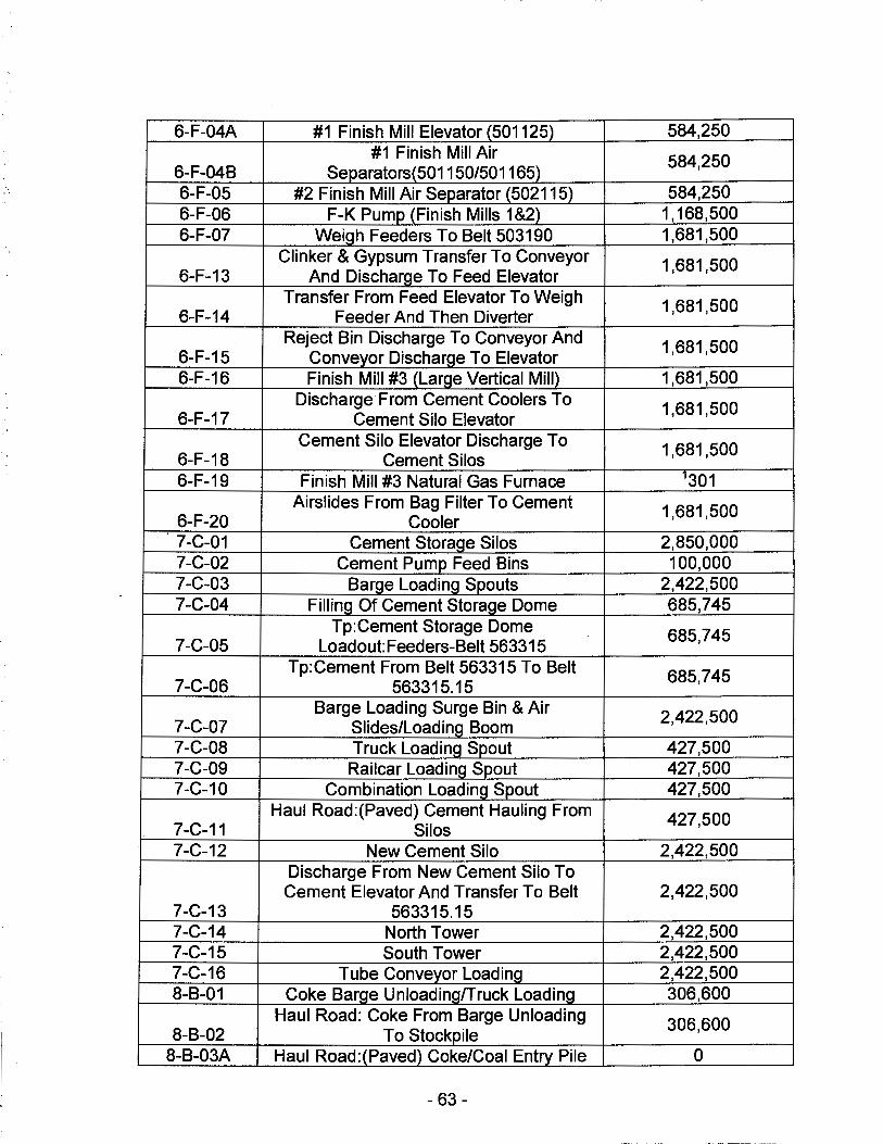
6-F-04A #1 Finish Mill Elevator (501125) 584,250 #1 Finish Mill Air 584,250
6-F-048 Separators(501150/501165) 6-F-05 #2 Finish Mill Air Separator (502115) 584,250 6-F-06 F-K Pump (Finish Mills 1 &2) 1,168,500 6-F-07 Weigh Feeders To Belt 503190 1,681,500
Clinker & Gypsum Transfer To Conveyor 1,681,500 6-F-13 And Discharge To Feed Elevator
Transfer From Feed Elevator To Weigh 1,681,500 6-F-14 Feeder And Then Diverter
Reject Bin Discharge To Conveyor And 1,681,500 6-F-15 Conveyor Discharge To Elevator 6-F-16 Finish Mill #3 (Large Vertical Mill) 1,681,500
Discharge From Cement Coolers To 1,681,500 6-F-17 Cement Silo Elevator
Cement Silo Elevator Discharge To 1,681,500 6-F-18 Cement Silos 6-F-19 Finish Mill #3 Natural Gas Furnace 1301
Airslides From Bag Filter To Cement 1,681,500 6-F-20 Cooler 7-C-01 Cement Storage Silos 2,850,000 7-C-02 Cement Pump Feed Bins 100,000 7-C-03 Barge Loading Spouts 2,422,500 7-C-04 Filling Of Cement Storage Dome 685,745
Tp:Cement Storage Dome 685,745 7-C-05 Load out: Feeders-Belt 563315
Tp:Cement From Belt 563315 To Belt 685,745 7-C-06 563315.15
Barge Loading Surge Bin & Air 2,422,500 7-C-07 Slides/Loading Boom 7-C-08 Truck Loading Spout 427,500 7-C-09 Railcar Loading Spout 427,500 7-C-10 Combination Loading Spout 427,500
Haul Road:(Paved) Cement Hauling From 427,500 7-C-11 Silos 7-C-12 New Cement Silo 2,422,500
Discharge From New Cement Silo To Cement Elevator And Transfer To Belt 2,422,500
7-C-13 563315.15 7-C-14 North Tower 2,422,500 7-C-15 South Tower 2,422,500 7-C-16 Tube Conveyor Loading 2,422,500 8-8-01 Coke Barge Unloading/Truck Loading 306,600
Haul Road: Coke From Barge Unloading 306,600 8-8-02 To Stockpile
8-B-03A Haul Road:(Paved) Coke/Coal Entry Pile 0
- 63 -
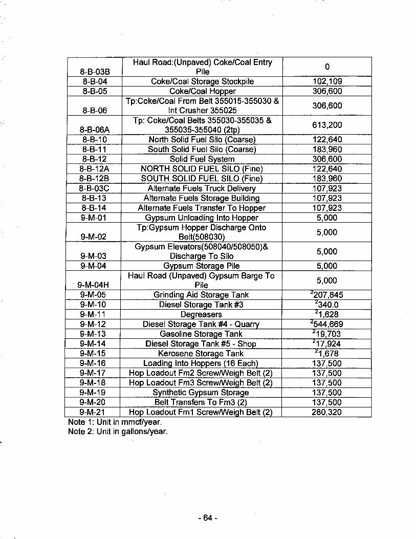
Haul Road:(Unpaved) Coke/Coal Entry 8-8-038 Pile 8-8-04 Coke/Coal Storage Stockpile 8-8-05 Coke/Coal Hopper
Tp:Coke/Coal From Belt 355015-355030 & 8-8-06 Int Crusher 355025
Tp: Coke/Coal Belts 355030-355035 & 8-B-06A 355035-355040 (2tp) 8-8-10 North Solid Fuel Silo (Coarse) 8-8-11 South Solid Fuel Silo (Coarse) 8-8-12 Solid Fuel System
8-B-12A NORTH SOLID FUEL SILO (Fine) 8-8-128 SOUTH SOLID FUEL SILO (Fine) 8-B-03C Alternate Fuels Truck Delivery 8-8-13 Alternate Fuels Storage Building 8-8-14 Alternate Fuels Transfer To Hopper 9-M-01 Gypsum Unloading Into Hopper
Tp:Gypsum Hopper Discharge Onto 9-M-02 Belt(508030)
Gypsum Elevators(508040/508050)& 9-M-03 Discharge To Silo 9-M-04 Gypsum Storage Pile
Haul Road (Unpaved) Gypsum Barge To 9-M-04H Pile 9-M-05 Grinding Aid Storage Tank 9-M-10 Diesel Storage Tank #3 9-M-11 Degreasers 9-M-12 Diesel Storage Tank #4 - Quarry 9-M-13 Gasoline Storage Tank 9-M-14 Diesel Storage Tank #5 - Shop 9-M-15 Kerosene Storage Tank 9-M-16 Loading Into Hoppers (16 Each) 9-M-17 Hop Loadout Fm2 Screw/Weigh Belt (2) 9-M~18 Hop Loadout Fm3 Screw/Weigh Belt (2) 9-M-19 Synthetic Gypsum Storage 9-M-20 Belt Transfers To Fm3 (2) 9-M-21 Hop Loadout Fm1 Screw/Weigh Belt (2)
Note 1: Unit in mmcf/year. Note 2: Unit in gallons/year.
- 64-
0
102,109 306,600
306,600
613,200
122,640 183,960 306,600 122,640 183,960 107,923 107,923 107,923 5,000
5,000
5,000
5,000
5,000
.!207,845 .!340.0 .!1,628
.!544,669 .!19,703 .!17,924 .!1,678
137,500 137,500 137,500 137,500 137,500 280,320
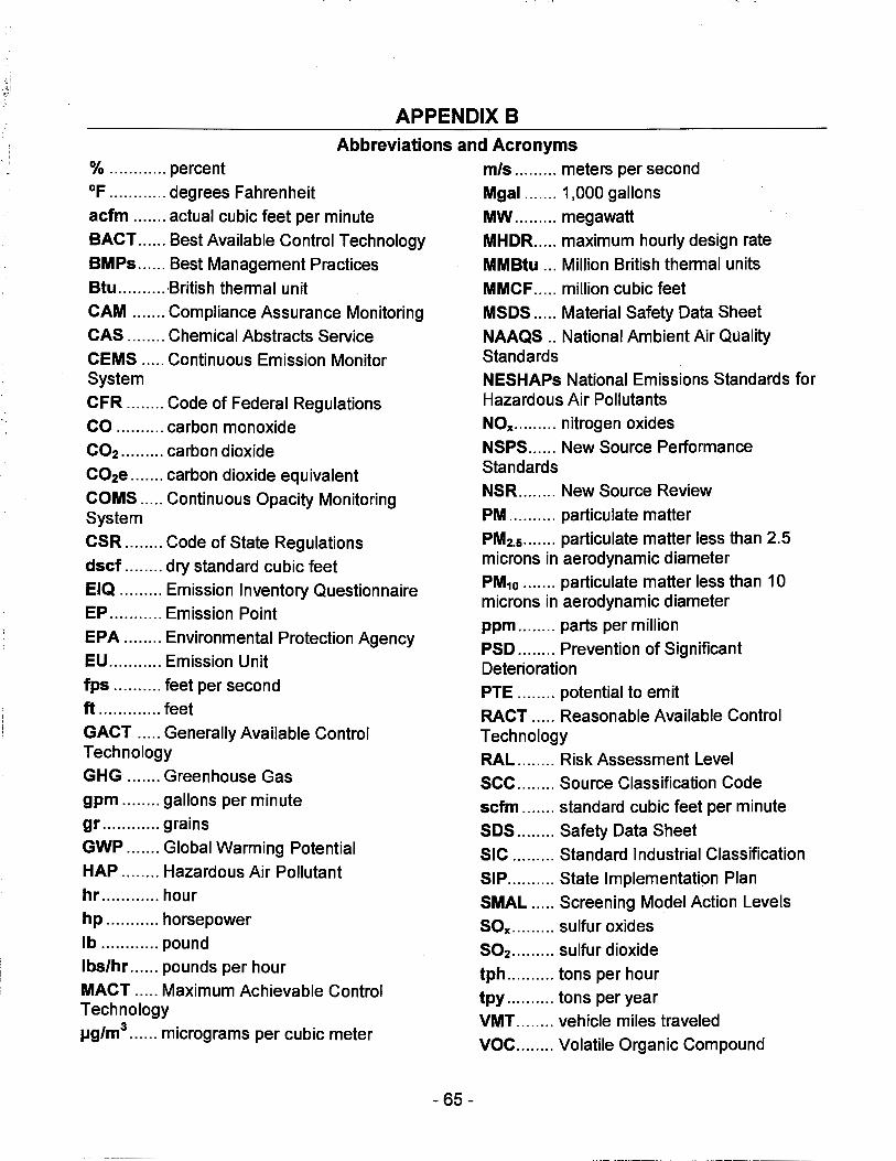
.-.f.,' :..~
APPENDIX B Abbreviations and Acronyms
% ............ percent
~F ............ degrees Fahrenheit
acfm ....... actual cubic feet per minute
BACT ...... Best Available Control Technology
BMPs ...... Best Management Practices
Btu .......... ,British thermal unit
CAM ....... Compliance Assurance Monitoring
CAS ........ Chemical Abstracts Service
CEMS ..... Continuous Emission Monitor System
CFR ........ Code of Federal Regulations
CO .......... carbon monoxide
CO2 ......... carbon dioxide
C02e ... .... carbon dioxide equivalent
COMS ..... Continuous Opacity Monitoring System
CSR ........ Code of State Regulations
dscf .... .... dry standard cubic feet
EIQ ......... Emission Inventory Questionnaire
EP ........... Emission Point
EPA ........ Environmental Protection Agency EU ........... Emission Unit
fps .......... feet per second
ft ............. feet
GACT ..... Generally Available Control Technology
GHG ....... Greenhouse Gas
gpm ........ gallons per minute gr ............ grains
GWP ....... Global Warming Potential
HAP ........ Hazardous Air Pollutant hr ............ hour
hp ........... horsepower
lb ............ pound
lbs/hr ...... pounds per hour
MACT ..... Maximum Achievable Control Technology
µg/m3 ...... micrograms per cubic meter
- 65 -
mis ......... meters per second
Mgal ....... 1,000 gallons
MW ......... megawatt
MHDR. .... maximum hourly design rate
MM Btu ... Million British thermal units
MMCF ..... million cubic feet
MSDS ..... Material Safety Data Sheet
NAAQS .. National Ambient Air Quality Standards NESHAPs National Emissions Standards for Hazardous Air Pollutants
NOx ......... nitrogen oxides
NSPS ...... New Source Performance Standards
NSR ........ New Source Review
PM .......... particulate matter
PM2.5 ....... particulate matter less than 2.5 microns in aerodynamic diameter
PM10 ....... particulate matter less than 10 microns in aerodynamic diameter
ppm ........ parts per million
PSD ........ Prevention of Significant Deterioration
PTE ........ potential to emit
RACT ..... Reasonable Available Control Technology
RAL ........ Risk Assessment Level
sec ........ Source Classification Code
scfm ... .... standard cubic feet per minute
SDS ........ Safety Data Sheet
SIC ......... Standard Industrial Classification
SIP .......... State Implementation Plan
SMAL ..... Screening Model Action Levels
SOx ......... sulfur oxides
502 ......... sulfur dioxide
tph .......... tons per hour
tpy .......... tons per year
VMT ........ vehicle miles traveled
voe ........ Volatile Organic Compound
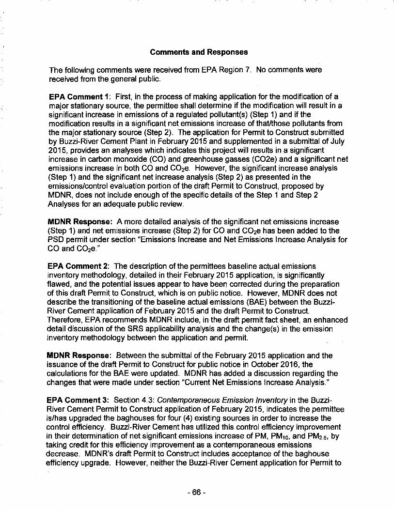
Comments and Responses
The following comments were received from EPA Region 7. No comments were received from the general public.
EPA Comment 1: First, in the process of making application for the modification of a major stationary source, the permittee shall determine if the modification will result in a significant increase in emissions of a regulated pollutant(s) (Step 1) and if the modification results in a significant net emissions increase of that/those pollutants from the major stationary source (Step 2). The application for Permit to Construct submitted by Buzzi-River Cement Plant in February 2015 and supplemented in a submittal of July 2015, provides an analyses which indicates this project will results in a significant increase in carbon monoxide (CO) and greenhouse gasses (C02e) and a significant net emissions increase in both CO and C02e. However, the significant increase analysis (Step 1) and the significant net increase analysis (Step 2) as presented in the emissions/control evaluation portion of the draft Permit to Construct, proposed by MDNR, does not include enough of the specific details of the Step 1 and Step 2 Analyses for an adequate public review.
MDNR Response: A more detailed analysis of the significant net emissions increase (Step 1) and net emissions increase (Step 2) for CO and C02e has been added to the PSD permit under section "Emissions Increase and Net Emissions Increase Analysis for CO and C02e."
EPA Comment 2: The description of the permittees baseline actual emissions inventory methodology, detailed in their February 2015 application, is significantly flawed, and the potential issues appear to have been corrected during the preparation of this draft Permit to Construct, which is on public notice. However, MDNR does not describe the transitioning of the baseline actual emissions (BAE) between the BuzziRiver Cement application of February 2015 and the draft Permit to Construct. Therefore, EPA recommends MDNR include, in the draft permit fact sheet, an enhanced detail discussion of the SRS applicability analysis and the change(s) in the emission inventory methodology between the application and permit.
MDNR Response: Between the submittal of the February 2015 application and the issuance of the draft Permit to Construct for public notice in October 2016, the calculations for the BAE were updated. MDNR has added a discussion regarding the changes that were made under section "Current Net Emissions Increase Analysis."
EPA Comment 3: Section 4.3: Contemporaneous Emission Inventory in the BuzziRiver Cement Permit to Construct application of February 2015, indicates the permittee is/has upgraded the baghouses for four (4) existing sources in order to increase the control efficiency. Buzzi-River Cement has utilized this control efficiency improvement in their determination of net significant emissions increase of PM, PM10, and PM2.5, by taking credit for this efficiency improvement as a contemporaneous emissions decrease. MDNR's draft Permit to Construct includes acceptance of the bag house efficiency upgrade. However, neither the Buzzi-River Cement application for Permit to
- 66 -
Construct nor the MDNR draft Permit to Construct provide any specific details regarding the upgrades to the four (4) Baghouses. MDNR should ensure that the public record for the final permit provides specific information on the efficiency improvements for each of the four (4) baghouses. Without specific review off the efficiency increase details, the ability to include as a contemporaneous decreased in emissions may be questionable.
Buzzi Response: In order to achieve the control efficiencies stated in the permit application for the baghouses cited in this comment, the BUU Festus Plant will physically modify the baghouses. The baghouses in question were installed decades ago. The baghouses will be converted from their existing Norblo technology, original to their installation, to a more modern Pulse-Jet technology. The Pulse-Jet technology will improve baghouse performance through more efficient operation and improved cleaning of bags, thereby improving the control efficiencies of the bag houses and allowing the BUU Festus Plant to achieve the 99% control identified in the application.
MDNR: MDNR has added the upgrade description as described in the Buzzi Response into the permit. Requirements for upgraded baghouses are included under Special Condition 6.
EPA Comment 4: Permit to Construct Application for a Major Modification to the Festus Plant, submitted by Buzzi-River Cement in February 2015, includes a Best Available Control Technology (BACT) analysis for both carbon monoxide (CO) and greenhouse gasses as C02e (GHG). BACT analysis is a 5-step top down review procedure to identify the optimum cost effective control technology to be adopted for each of the specific pollutants. Buzzi-River Cement determined that GHG BACT analysis were necessary for their preheater/precalciner kiln system; an 815 horsepower diesel-fired emergency generator; and the Finish Mill #3 Furnace. Buzzi-River Cement application presents a detailed 5-step C02e and CO BACT analysis for the preheater/precalciner kiln system. However, Buzzi-River Cement cuts short the C02e and CO BACT 5-step process for the emergency generator and the Finish Mill #3 Furnace and presents their C02e and CO BACT solution without executing the 5-Step BACT analysis. DNR should ensure that the public record for the final permit describes the full 5-step C02e and CO BACT analysis for the emergency generator and Finish Mill #3 furnace.
Buzzi Response: Provided below is a five-step BACT analysis for CO and GHG (as C02e) for. the BUU Festus Plant (Plant) Emergency Generator and Finish Mill #3 Furnace.
1. CO BACT Analysis - Emergency Generator
The Emergency Generator is an 815 horsepower (hp) diesel-fired engine which is operated for routine maintenance and testing, or in the event of a power outage at the Plant. As a result, the Emergency Generator is operated intermittently during the year and is limited to operate no more than 500 hours per year. The PTE CO emissions from the Emergency Generator were estimated using the manufacturer guaranteed CO emission rate of 1.06E-3 lb/hp-hr, which is equivalent to 0.48 g/hp-hr. Given the Emergency Generator's limited hours of operation per year, the annual PTE CO emission was estimated to be 0.22 tons per year which represents approximately 0.01
- 67 -
·' >
percent of the total facility-wide PTE CO emissions.
Provided below is a five-step CO BACT Analysis for the Emergency Generator.
• Step 1: Identify all control technologies
The first step in the BACT analysis is to identify all potential control technologies for each assessed air pollutant. Two potential control technologies were found to be applicable to the Emergency Generator and are as follows:
Proper Design (Good Combustion Practices) - Catalytic Oxidation
• Step 2: Eliminate technically infeasible options
Because of the intermittent hours of operation (i.e., maximum of 500 hours/year) and corresponding low CO annual emissions of the Emergency Generator, post-combustion control technology such as catalytic oxidation has never been demonstrated or required as CO BACT for a cement plant's Emergency Generator. A review of the U.S. EPA RACT/BACT/LAER Clearinghouse (RBLC) confirms that post-combustion control technology has not been required to be installed as CO BACT for any cement plant Emergency Generator because of the inherent intermittent operation of the Emergency Generator. Additionally, use of post-combustion control technology, such as catalytic oxidation, would be expected to be prohibitively expensive. For these reasons, catalytic oxidation has been eliminated from further consideration.
• Step 3: Rank remaining control technologies by control effectiveness
Proper Design (Good Combustion Practices) is the only remaining technically feasible control technology.
• Step 4: Evaluate most effective controls and document results
Use of Proper Design (Good Combustion Practices) results in a PTE CO emission rate from the Emergency Generator of 0.22 tons per year, which represents approximately 0.01 percent of the total facility-wide PTE annual CO emissions.
• Step 5: Select BACT
Proper Design (Good Combustion Practices) has been determined to be CO BACT for the Emergency Generator. The proposed CO BACT will not have any adverse environmental or energy impacts.
2. CO BACT Analysis - Finish Mill #3 Furnace
Finish Mill #3 is equipped with a natural gas-fired furnace to dry the finish grinding materials. The Finish Mill #3 Furnace is used intermittently during very cold ambient conditions experienced in the winter months. The Finish Mill #3 Furnace is natural gasfired and utilizes a 35 MMBtu/hr thermal dryer, as needed, to dry the finish grinding
- 68 -
materials (i.e., clinker and gypsum), which are processed by Finish Mill #3 to produce a product, Portland cement. The Finish Mill #3 Furnace was designed to only utilize natural gas as a fuel and has a potential throughput usage rate of 300.6 million standard cubic feet (MMscf) per year of natural gas. CO emissions from the Finish Mill #3 Furnace are emitted to the atmosphere through the Finish Mill #3 stack. The Finish Mill #3 Furnace utilizes the latest state-of-the-art combustion efficiency technology at the time of its construction in 2008.
The Finish Mill #3 Furnace PTE CO annual emission rate is 12.6 tons per year and was estimated using U.S. EPA's AP-42 Section 1.4 CO emission factor of 84 lb/MMscf, applicable for uncontrolled small (less than 100 MM Btu/hr) natural gas fired boilers. The PTE CO annual emission rate from the Finish Mill #3 Furnace represents approximately 0.4 percent of the total facility-wide PTE CO annual emissions.
Provided below is a five-step CO BACT Analysis for the Finish Mill #3 Furnace.
• Step 1: Identify all control technologies
The first step in the BACT analysis is to identify all potential control technologies for each assessed air pollutant. Two potential control technologies were found to be applicable to the Finish Mill #3 Furnace and are as follows:
Proper Design (Good Combustion Practices) Catalytic Oxidation
• Step 2: Eliminate technically infeasible options
Because of the intermittent operation and the low annual CO emission rate of the Finish Mill #3 Furnace, post-combustion controls such as catalytic oxidation has never been demonstrated or required as CO BACT on a cement plant's Finish Mill Furnace. A review of the U.S. EPA RBLC confirms that CO post-combustion control technology has never been required to meet CO BACT for a cement plant finish mill furnace because of the inherent intermittent operation of a finish mill furnace. Additionally, use of postcombustion control technology, such as catalytic oxidation, would be expected to be prohibitively expensive. For these reasons, catalytic oxidation has been eliminated from further consideration.
• Step 3: Rank remaining control technologies by control effectiveness
Proper Design (Good Combustion Practices) is the only remaining technically feasible control technology.
• Step 4: Evaluate most effective controls and document results
Use of Proper Design (Good Combustion Practices) results in a PTE CO annual emission rate from the Finish Mill #3 Furnace of 12.6 tons per year and represents approximately 0.4 percent of the total facility-wide PTE CO annual emissions.
- 69 -
• Step 5: Select BACT
Proper Design (Good Combustion Practices) has been determined as CO BACT for the Finish Mill #3 Furnace. The proposed CO BACT will not have any adverse environmental or energy impacts.
3. GHG BACT Analysis - Emergency Generator
The Emergency Generator is an 815 horsepower (hp) diesel-fired engine which is only operated for routine maintenance and testing, or in the event of a power outage. As a result, the Emergency Generator is operated intermittently during the year and limited to operate no more than 500 hours per year. The PTE GHG (as C02e) emissions from the Emergency Generator were estimated using 40 CFR 98 Subpart C GHG emission factors (11/9/2013) and Subpart A Table A-1 (12/11/14) global warming potentials. Based on the Emergency Generator being limited to a maximum of 500 hours of operation per year, the PTE GHG annual emission rate from the Emergency Generator is estimated to be 241 tons C02e per year, which represents approximately 0.01 percent of the total facility-wide PTE GHG annual emissions.
Provided below is a five-step GHG BACT Analysis for the Emergency Generator.
• Step 1: Identify all control technologies
The first step in the BACT analysis is to identify all potential control technologies for each assessed air pollutant. Two potential control technologies were found to be applicable to the Emergency Generator and are as follows:
Use of Both Diesel Fuel and Good Combustion Practices Use of Both Natural Gas Fuel and Good Combustion Practices
• Step 2: Eliminate technically infeasible options
A natural gas-fired Emergency Generator engine would be expected to emit less GHG (i.e., C02e) than a diesel-fired Emergency Generator engine. However, the Emergency Generator engine is intended for use only in the event of a plant-wide power outage, which usually results in the interruption of the supply of natural gas. Therefore, natural gas is not considered to be technically feasible for use as a fuel for the 815 hp Emergency Generator engine. An onsite diesel fuel tank is the only uninterruptible fuel supply available for this type of Emergency Generator engine.
• Step 3: Rank remaining control technologies by control effectiveness
Use of both diesel fuel and good combustion practices for the Emergency Generator is the only remaining technically feasible control technology.
• Step 4: Evaluate most effective controls and document results
Use of both diesel fuel and good combustion practices for the Emergency Generator results in a PTE C02e annual emission rate from the Emergency Generator of 241 tons
- 70 -
'·
per year, which represents approximately 0.01 percent of the total facility-wide PTE C02e annual emissions.
• Step 5: Select BACT
Use of both diesel fuel and good combustion practices for the Emergency Generator has been determined to represent GHG BACT. The proposed GHG BACT was assessed to have no adverse environmental or energy impacts.
4. GHG BACT Analysis - Finish Mill #3 Furnace
Finish Mill #3 is equipped with a natural gas-fired furnace to dry the finish grinding materials. This furnace is used intermittently, but especially during very cold ambient conditions experienced during the winter season. The natural gas-fired furnace utilizes a 35 MMBtu/hr thermal dryer, as needed, to dry the finish grinding materials (i.e., clinker and gypsum), which is processed by Finish Mill #3 into a product, Portland cement. The Finish Mill #3 Furnace utilizes natural gas as a fuel and has a potential throughput of 300.6 million standard cubic feet (MMscf) per year of natural gas. C02e emissions from the Finish Mill #3 Furnace are emitted to the atmosphere through the Finish Mill #3 stack. The Finish Mill #3 Furnace utilizes the latest state-of-the-art combustion efficiency technology at the time of its construction in 2008.
The Finish Mill #3 Furnace PTE C02e emissions are 18,057 tons per year and were estimated using 40 CFR 98 Subpart C GHG emission factors (11/9/2013) and Subpart A, Table A-1 (12/11/14) GHG global warming potentials. The PTE annual C02e emission rate of 18,057 tons per year from the Finish Mill #3 Furnace represents approximately 0. 75 percent of the total facility-wide PTE C02e annual emissions.
Provided below is a five-step GHG BACT Analysis for the Finish Mill #3 Furnace.
• Step 1: Identify all control technologies
The first step in the BACT analysis is to identify all potential control technologies for each assessed air pollutant. Two potential control technologies were found to be applicable to the Finish Mill #3 Furnace and are as follows:
Use of Both Diesel Fuel and Good Combustion Practices Use of Both Natural Gas Fuel and Good Combustion Practices
• Step 2: Eliminate technically infeasible options
Both options listed in Step 1 are considered technically feasible for the Finish Mill #3 Furnace.
• Step 3: Rank remaining control technologies by control effectiveness
Table 3a was developed to rank the cost effectiveness of the use of diesel and natural gas as potential fuel for the Finish Mill #3 Furnace. The PTE set/year of natural gas was first calculated and the corresponding required MMBTU/year was estimated. The
- 71 -
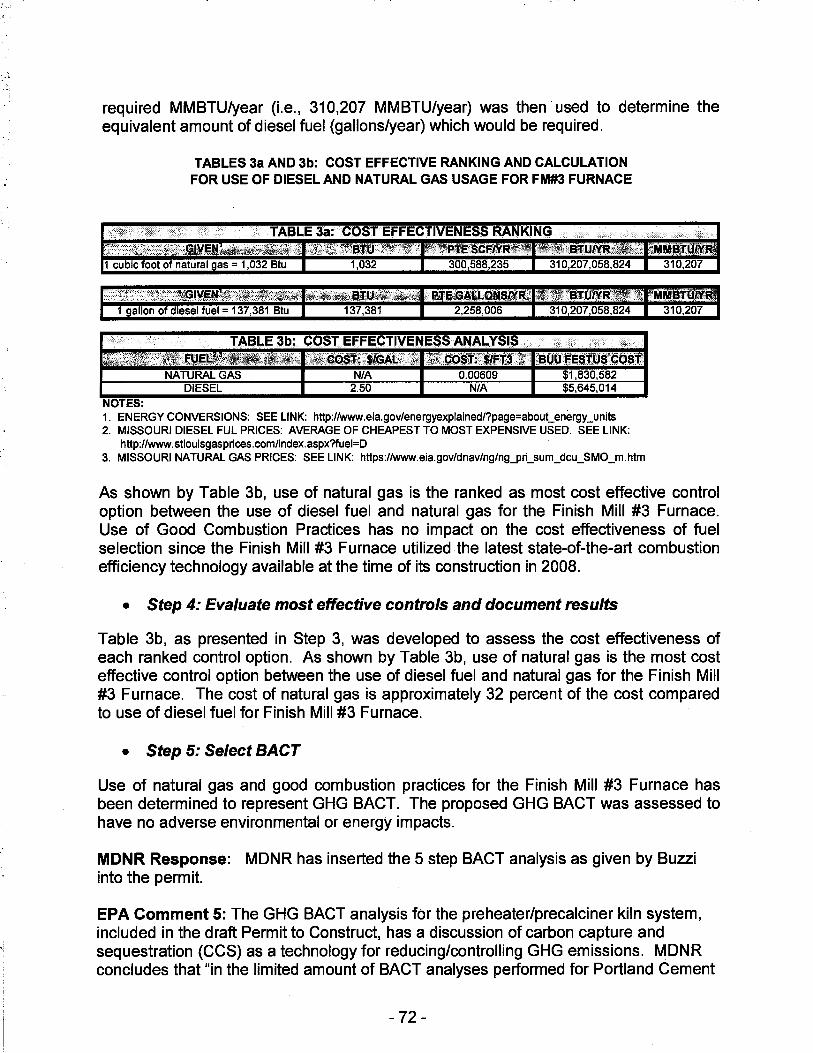
required MMBTU/year (i.e., 310,207 MMBTU/year) was then used to determine the equivalent amount of diesel fuel (gallons/year) which would be required.
NOTES:
TABLES 3a AND 3b: COST EFFECTIVE RANKING AND CALCULATION FOR USE OF DIESEL AND NATURAL GAS USAGE FOR FM#3 FURNACE
2,258,006
TABLE 3b: COST EFFECTIVENESS ANALYSIS ..
·" "'· ,,,.... '·"::if~i}tI?~ r!?Zfi:¢:gs'f{JlGjt.:{:j;: \1rzr:co::;I1'lt•1~ii:1t? ;~u~~ije.slui'.4Q'$.J: NATURAL GAS N/A 0.00609 $1,830,582
DIESEL 2.50 N/A $5,645,014
1. ENERGY CONVERSIONS: SEE LINK: http://www.eia.gov/energyexplained/?page=about_energy_units 2. MISSOURI DIESEL FUL PRICES: AVERAGE OF CHEAPEST TO MOST EXPENSIVE USED. SEE LINK:
http://www.stlouisgasprices.com/index.aspx?fuel=D 3. MISSOURI NATURAL GAS PRICES: SEE LINK: https://www.eia.gov/dnav/ng/ng_pri_sum_dcu_SMO_m.htm
As shown by Table 3b, use of natural gas is the ranked as most cost effective control option between the use of diesel fuel and natural gas for the Finish Mill #3 Furnace. Use of Good Combustion Practices has no impact on the cost effectiveness of fuel selection since the Finish Mill #3 Furnace utilized the latest state-of-the-art combustion efficiency technology available at the time of its construction in 2008.
• Step 4: Evaluate most effective controls and document results
Table 3b, as presented in Step 3, was developed to assess the cost effectiveness of each ranked control option. As shown by Table 3b, use of natural gas is the most cost effective control option between the use of diesel fuel and natural gas for the Finish Mill #3 Furnace. The cost of natural gas is approximately 32 percent of the cost compared to use of diesel fuel for Finish Mill #3 Furnace.
• Step 5: Select BACT
Use of natural gas and good combustion practices for the Finish Mill #3 Furnace has been determined to represent GHG BACT. The proposed GHG BACT was assessed to have no adverse environmental or energy impacts.
MDNR Response: MDNR has inserted the 5 step BACT analysis as given by Buzzi into the permit.
EPA Comment 5: The GHG BACT analysis for the preheater/precalciner kiln system, included in the draft Permit to Construct, has a discussion of carbon capture and sequestration (CCS) as a technology for reducing/controlling GHG emissions. MDNR concludes that "in the limited amount of BACT analyses performed for Portland Cement
- 72 -
Plants, CCS that have been considered technically feasible has always been considered infeasible due to environmental, energy or economic reasons," EPA notes that the cost issues related to CCS ·implementations may in fact be a valid reason to eliminate CCS from BACT consideration, but a full cost analysis should be conducted under Step 4 of the top-down BACT analysis to support the decision.
MDNR Response: A site-specific full cost analysis cannot be performed for CCS because this technology is not currently available commercially. However, some generalized cost analysis can be found in literature. MDNR will add the generalized cost analysis into the permit to show that CCS should be eliminated on economic grounds.
EPA Comment 6: Special Conditions 4.C., D., and E. Provide GHG-C02e BACT limits on the preheater/precalciner kiln system of 0.95 tons C02e/ton of clinker based on a 12-month rolling average; 18,057.0 tons C02e/year from the finish Mill #3 Furnace based on 12-month rolling total; and 241 tons C02e/year from the emergency generator based on a 12-month rolling total, respectively. However, these special conditions are unclear as to the frequency of the C02e determination and how often the 12-month totals are rolled. EPA recommends MDNR provide additional clarity as to the permittee's frequency of C02e emission determination and how often the data is rolled.
MDNR Response: MDNR has added clarification as to how often the data is rolled in Special Conditions 4.C., 4.D., and 4.E.
EPA Comment 7: Special Condition 10.C. requires the permittee to maintain baghouse pressure drop within the values required for proper baghouse operation. It appears that MDNR did not include the method for the permittee to use to determine this pressure drop range and there are no required actions to be undertaken by the permittee when the pressure drop is outside the proper range. EPA recommends MDNR provide the pressure drop determil"!ation methodology and corrective actions to be taken by the permittee when pressure drop range is violated.
MDNR Response: The pressure range should not be specified because they vary with different baghouses. However, MDNR will add that the facility "should maintain the pressure within the values identified in the manufacturer's specifications." Furthermore, the facility will now be required to perform corrective actions to bring the pressure drop back into the acceptable range should it deviate from this range. The specific corrective actions cannot be identified because it would depend on the type of malfunction.
EPA Comment 8: Special Condition 12.C. requires the permittee to "periodically water, wash or otherwise clean all of the paved portions of haul roads as necessary." Special Condition 12 doesn't include the action(s) that would trigger the need for the permittee to periodically water, wash or otherwise clean the haul roads. EPA recommends MDNR specify the conditions whereby the permittee will have to water, wash or otherwise clean the haul roads.
- 73 -
MDNR Response: In Special Condition 12, the permittee is required to test to ensure that the silt content of the paved haul roads are less than 3.0 g/m2 and to clean the haul roads using the same frequency and method of the cleaning cycle used during the compliant silt content test. Furthermore, the purpose of the special condition is to ensure that the facility wash and clean the roads when enough dust accumulates on the road to where excess emissions may be emitted. There is no specific "action" that would trigger the need for watering and cleaning.
EPA Comment No. 9: Finally, Table 18: Ranking of Control Effectiveness is included within Step 3 of the CO BACT Analysis and provides a ranking of the control technologies considered CO BACT by control effectiveness. Additionally, Table 20: Ranking of Control Effectiveness is included within Step 3 of the. GHG BACT analysis and provides a ranking of the control technologies considered GHG BACT by control effectiveness. However, there does not appear to be any reference provided, with either Table 18 or Table 20, to support the data included within the tables. EPA recommends MDNR specify the source of the data used to rank the control technologies by control effectiveness.
Buzzi Response:
CO BACT Analysis
The following references were used to determine the ranking of cost effectiveness presented in Table 18 for the CO BACT analysis for the PH/PC kiln system.
1. Summary of Environmental and Cost Impacts for Final Amendments to Portland Cement NESHAP (40 CFR Part 63, Subpart LLL). Docket No. EPA-HQ-OAR-2002-0051. August 6, 2010
2. EPA Air Pollution Control Cost Manual. Sixth Edition. EPA/452/B-02-001. January 2002.
3. U.S. Inflation Calculator, http://www.usinflationcalculator.com/
4. Laney, M., D. Green and K Barnett 2006. Summary of Environmental and Cost Impacts of Final Amendments to Portland Cement NESHAP, December 8, 2006, Docket item EPA-HQ-OAR-2002-0051-1891.
GHG BACT Analysis The following references were used to determine the ranking of cost effectiveness presented in Table 20 for the GHG BACT analysis for the PH/PC kiln system.
1. Cement Sustainability Initiative, World Business Council for Sustainable Development, "The CO2 Protocol, CO2 Accounting and Reporting Standard for the Cement Industry", June 2005.
- 74 -
2. Federal Register: 40 CFR 60 and Part 241, "Commercial and Industrial Solid Waste Incineration Units: Reconsideration and Final Amendments and NonHazardous Secondary Materials That Are Solid Waste; Final Rule", February 7, 2013.
3. U.S. EPA, Office of Air and Radiation, "Available and Emerging Technologies for Reducing Greenhouse Gas Emissions from the Portland Cement Industry", October 2010.
4. U.S. EPA, Office of Air Quality Planning and Standards, "New Source Review Workshop Manual", Draft October 1990.
5. Cement Sustainability Initiative, World Business Council for Sustainable Development, "Development of State of the Art-Techniques in Cement Manufacturing: Trying to Look Ahead", (CSI/ECRA- Technology Papers), Section 3.9, June 2009.
6. Cement Sustainability Initiative, World Business Council for Sustainable Development, "Development of State of the Art-Techniques in Cement Manufacturing: Trying to Look Ahead", (CSI/ECRA- Technology Papers), Section 2.4.3, June 2009.
7. Website: http://www.nrmca.org/research/CIF%2006-4%20Tech%20Talk.pdf, "The Impact of Fly Ash on Air Entrained Concrete", HPC Bridge Views Issue No. 32, March/April 2004.
8. Cement Sustainability Initiative, World Business Council for Sustainable Development, "Development of State of the Art-Techniques in Cement Manufacturing: Trying to Look Ahead", (CSI/ECRA- Technology Papers), Section 2.1.3, June 2009. ·
9. U.S. EPA, Office of Air Quality Planning and Standards, Alternative Control Techniques Document Update - NOx Emissions from New Cement Kilns, EPA-453/R-07-006, November 2007.
10. U.S. Energy Administration, Florida, Website: http://www.eia.gov/ state/data.cfm?sid=FL .
11. Holcim (US) Inc., "Permit To Construct Application, Hagerstown Plant", Page 6-19, July 2013.
MDNR Response: MDNR has instead the references as given by Buzzi into the permit.
- 75 -

. ·~· '_ .. ::
D
JAN t 8 2017
Mr. Adam Swercheck Buzzi Unicem USA - Festus Plant 100 Brodhead Road Bethlehem, PA 18017-8989
dnr.mn.gnv
RE: New Source Review Permit - Project Number: 2015-03-005
Dear Mr. Swercheck:
Enclosed with this letter is your permit to construct. Please study it carefully and refer to Appendix A for a list of common abbreviations and acronyms used in the permit. Also, note the special conditions, if any, on the accompanying pages. The document entitled, "Review of Application for Authority to Construct," is part of the permit and should be kept with this permit in your files. Operation in accordance with these conditions, your new source review permit application and with your amended operating permit is necessary for continued compliance. The reverse side of your permit certificate has important information concerning standard permit conditions and your rights and obligations under the laws and regulations of the State of Missouri.
This permit may include requirements with which you may not be familiar. If you would like the department to meet with you to discuss how to understand and satisfy the requirements contained in this permit, an appointment referred to as a Compliance Assistance Visit (CA V) can be set up with you. To request a CAV, please contact your local regional office or fill out an online request. The regional office contact information can be found at the following website: http://dnr.mo.gov/regions/. The online CAV request can be found at http://dnr.mo.gov/cav/compliance.htm.
If you were adversely affected by this permit decision, you may be entitled to pursue an appeal before the administrative hearing commission pursuant to Sections 621.250 and 643.075.6 RSMo. To appeal, you must file a petition with the administrative hearing commission within thirty days after the date this decision was mailed or the date it was delivered, whichever date was earlier. If any such petition is sent by registered mail or certified mail, it will be deemed filed on the date it is mailed; if it is sent by any method other than registered mail or certified mail, it will be deemed filed on the date it is received by the administrative hearing commission, whose contact information is: Administrative Hearing Commission, United States Post Office Building, 131 West High Street, Third Floor, P.O. Box 1557, Jefferson City, Missouri 65102, phone: 573-751-2422, fax: 573-751-5018, website: www.oa.mo.gov/ahc.
Recycled papvt
·I ·.j
I 1
!
·I
Mr. Adam Swercheck Page Two
If you have any questions regarding this permit, please do not hesitate to contact Chia-Wei Young, at the Department of Natural Resources' Air Pollution Control Program, P.O. Box 176, Jefferson City, MO 65102 or at (573) 751-4817. Thank you for your attention to this matter.
Sincerely,
AIR POLLUTION CONTROL PROGRAM
Susan Heckenkamp New Source Review Unit Chief
SH:cyj
Enclosures
c: St. Louis Regional Office PAMS File: 2015-03-005
Permit Number: 01 2 0 1 7 - 0 0 9