Embed Size (px)
Citation preview
5/14/2018 Witricity Wireless Power Transmission - slidepdf.com
http://slidepdf.com/reader/full/witricity-wireless-power-transmission-55a931a50fa8b
A Paper presentation on…
WITRICITY
(WIRELESS POWER
TRANSMISSION)
5/14/2018 Witricity Wireless Power Transmission - slidepdf.com
http://slidepdf.com/reader/full/witricity-wireless-power-transmission-55a931a50fa8b
ABSTRACT:
The aim of this paper is to introduce a
new system of transmitting the power
which is called wireless electricity or witricity. Witricity is based upon
coupled resonant objects to transfer
electrical energy between objects
without wires. The system consists of a
Witricity transmitter (power source),
and devices which act as receivers
(electrical load). It is based on the
principle of resonant coupling and
microwave energy transfers. The action
of an electrical transformer is the
simplest instance of wireless energy
transfer. There are mainly two types of
transfers i.e. short range and long range
transmission. The short range are of 2-
3metres where as the long range are of
few kilometers.
Wireless transmission is ideal in cases
where instantaneous or continuousenergy transfer is needed, but
interconnecting wires are inconvenient,
hazardous, or impossible. The tangle of
cables and plugs needed to recharge
today's electronic gadgets could soon be
a thing of the past. The concept exploits
century-old physics and could work
over distances of many metres.
Consumers desire a simple universal
solution that frees them from the
hassles of plug-in chargers and
adaptors. "Wireless power technology
has the potential to deliver on all of
these needs." However, transferring the
power is the important part of the
solution.
Witricity, standing for wireless
electricity, is a term coined by MITresearchers, to describe the ability to
provide electricity to remote objects
without wires. Using self-resonant
coils in a strongly coupled regime,
efficient non-radiative power transfer
over distances of up to eight times theradius of the coils can be done..
Unlike the conduction-based systems,
Witricity uses resonant magnetic
fields to reduce wastage of power.
Currently the project is looking for
power transmissions in the range of
100 watts.
With wireless energy transfer, the
efficiency is a more critical parameter
and this creates important differences
from the wireless data transmission
technologies. To avoid the conflicts like
recharging and carrying its appliances
of electrical and electronic devices,
wireless power transmission is
desirable. Wireless power transmission
was originally proposed to avoid long
distance electrical distribution basedmainly on copper cables. This can be
achieved by using microwave beams
and the rectifying antenna, or rectenna,
which can receive electromagnetic
radiation and convert it efficiently to
DC electricity. Researchers have
developed several techniques for
moving electricity over long distances
without wires. Some exist only as
theories or prototypes, but others are
already in use. Magnetic resonance was
found a promising means of electricity
transfer because magnetic fields travel
freely through air yet have little effect
on the environment or, at the
appropriate frequencies, on living
beings and hence is a leading
technology for developing witricity.
5/14/2018 Witricity Wireless Power Transmission - slidepdf.com
http://slidepdf.com/reader/full/witricity-wireless-power-transmission-55a931a50fa8b
HOW IT WORKS-
Wireless light: Researchers used
magnetic resonance coupling to power a 60-watt light bulb. Tuned to the same
frequency, two 60-centimeter copper
coils can transmit electricity over a
distance of two meters, through the air
and around an obstacle.
The researchers built two resonant
copper coils and hung them from the
ceiling, about two meters apart.
When they plugged one coil into the
wall, alternating current flowed through
it,
Creating a magnetic field.
The second coil, tuned to the same
frequency and hooked to a light bulb,
resonated with the magnetic field,
generating an electric current that lit up
the bulb--even with a thin wall between
the coils.
How wireless energy could
work-
"Resonance", a phenomenon that
causes an object to vibrate when energy
of a certain frequency is applied. Two
resonant objects of the same frequency
tend to couple very strongly."
Resonance can be seen in musical
instruments for example. "When you
play a tune on one, then another
instrument with the same acoustic
resonance will pick up that tune, it will
visibly vibrate,"
Instead of using acoustic vibrations,
system exploits the resonance of
electromagnetic waves.
Electromagnetic radiation includes
radio waves, infrared and X-rays.
Typically, systems that useelectromagnetic radiation, such as radio
antennas, are not suitable for the
efficient transfer of energy because they
scatter energy in all directions, wasting
large amounts of it into free space.
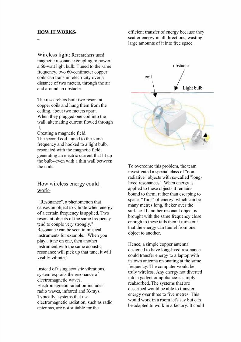
obstacle
coil
Light bulb
To overcome this problem, the team
investigated a special class of "non-
radiative" objects with so-called "long-lived resonances". When energy is
applied to these objects it remains
bound to them, rather than escaping to
space. "Tails" of energy, which can be
many metres long, flicker over the
surface. If another resonant object is
brought with the same frequency close
enough to these tails then it turns out
that the energy can tunnel from one
object to another.
Hence, a simple copper antenna
designed to have long-lived resonance
could transfer energy to a laptop with
its own antenna resonating at the same
frequency. The computer would be
truly wireless. Any energy not diverted
into a gadget or appliance is simply
reabsorbed. The systems that are
described would be able to transfer
energy over three to five metres. This
would work in a room let's say but can be adapted to work in a factory. It could
5/14/2018 Witricity Wireless Power Transmission - slidepdf.com
http://slidepdf.com/reader/full/witricity-wireless-power-transmission-55a931a50fa8b
also be scaled down to the microscopic
or nanoscopic world.
HOW WIRELESS POWER COULD WORK
1. Power from mains to antenna, which is made of copper
2. Antenna resonates at a frequency of 6.4MHz, emitting electromagnetic waves
3. 'Tails' of energy from antenna 'tunnel' up to 5m (16.4ft)
4. Electricity picked up by laptop's antenna, which must also be resonating at 6.4MHz.
Energy used to re-charge device
5. Energy not transferred to laptop re-absorbed by source antenna.
People/other objects not affected as not resonating at 6.4MHz
Short range powertransmission and
reception –
Power supply for portable electronic
devices is considered, which
receives ambient radio frequency
radiation (typically in an urban
environment) and converts it to
DC electricity that is stored in a
battery for use by the portabledevice.
A Power transmission unit (PTU)
is connected to the electrical
utility, typically in a domestic and
office environment, and uses the
electricity to generate a beam of
electromagnetic radiation. This
beam can take the form of visible
light, microwave radiation, near
infrared radiation or anyappropriate frequency or
frequencies, depending on the
technology chosen. The beam can
be focused and shaped using a
focusing mechanism: for
example, a parabola shape may
be chosen to focus light waves at
a certain distance from the PTU.
A Power reception unit (PRU)
receives power from one or
several PTU's, and converts the
total power received to
electricity, which is used to
trickle charge a storage unit such
as a battery or transferred directly
to the appliance for use, or both.
If transferred to the storage unit,the output of the storage unit can
power the appliance. Similarly to
the focusing of the transmitted
power, it is possible to
concentrate the received power
for conversion, using receiving
arrays, antennas, reflectors or
similar means.
It is possible to construct power
"relay units", consisting of PRU's powering PTU's, whose function
is to make the transmitted power
available at further distances than
would normally be possible.
Long-distance Wireless Power-
Some plans for wireless power involve
moving electricity over a span of miles.
A few proposals even involve sending power to the Earth from space. The
Stationary High Altitude Relay
Platform (SHARP) unmanned plane
could run off power beamed from the
Earth. The secret to the SHARP's long
flight time was a large, ground-based
microwave transmitter. A large, disc-
shaped rectifying antenna, or
rectenna, near the system changed the
microwave energy from the transmitter
into direct-current (DC) electricity.Because of the microwaves' interaction
with the rectenna, the system had a
constant power supply as long as it was
in range of a functioning microwave
array.
Rectifying antennae are central to many
wireless power transmission theories.
They are usually made of an array of
dipole antennae, which have positive
and negative poles. These antennae
5/14/2018 Witricity Wireless Power Transmission - slidepdf.com
http://slidepdf.com/reader/full/witricity-wireless-power-transmission-55a931a50fa8b
connect to semiconductor diodes.
Here's what happens:
1. Microwaves, which are part of
the electromagnetic spectrum,
reach the dipole antennae.2. The antennae collect the
microwave energy and transmit
it to the diodes.
3. The diodes act like switches that
are open or closed as well as
turnstiles that let electrons flow
in only one direction. They
direct the electrons to the
rectenna's circuitry.
4. The circuitry routes the
electrons to the parts andsystems that need them. .
TYPES OF WIRELESS
TRANSMISSION-
Near field
Induction
Resonant induction
Far field
Radio and microwave transmission
Laser
Electrical conduction
Near field-
These are wireless transmission
techniques over distances comparable
to, or a few times the diameter of the
device(s).
Induction
Inductive couplingThe action of an
electrical transformer is the simplest
instance of wireless energy transfer.The primary and secondary circuits of a
transformer are not directly connected.
The transfer of energy takes place by
electromagnetic coupling through a
process known as mutual induction.
(An added benefit is the capability to
step the primary voltage either up or down.) The battery charger of an
electric toothbrush is an example of
how this principle can be used. The
main drawback to induction, however,
is the short range. The receiver must be
very close to the transmitter or
induction unit in order to inductively
couple with it.
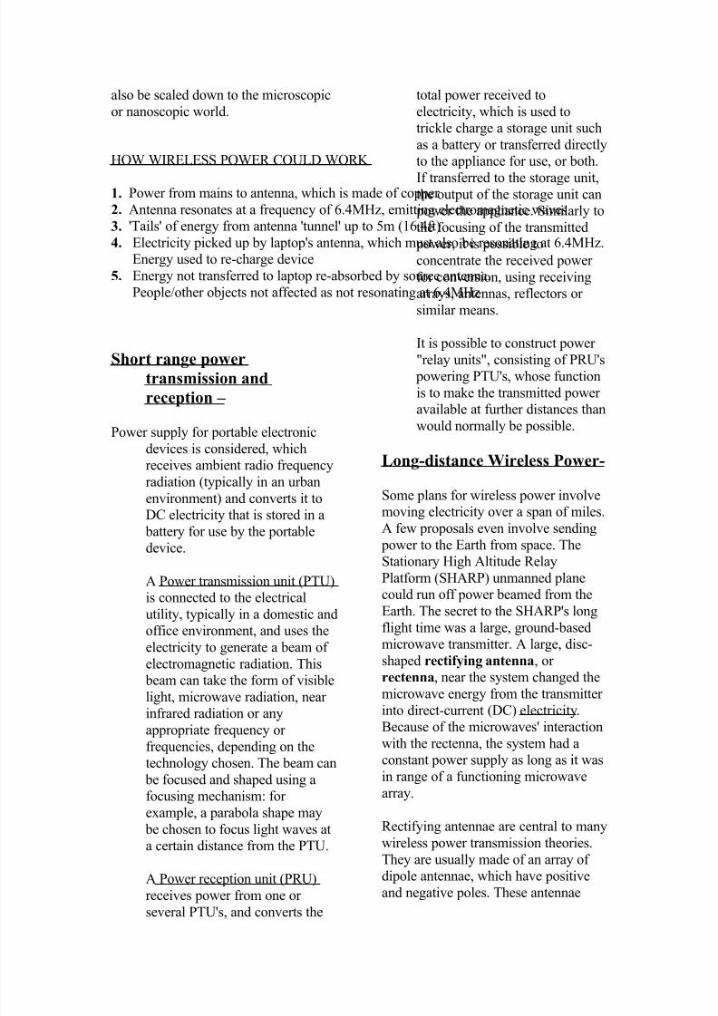
Resonant induction
By designing electromagnetic
resonators that suffer minimal loss due
to radiation and absorption and have a
near field with mid-range extent
(namely a few times the resonator size),
mid-range efficient wireless energy-
transfer is possible. The reasonment is
that, if two such resonant objects are
brought in mid-range proximity, their
near fields (consisting of so-called
'evanescent waves') couple (evanescentwave coupling) and can allow the
According to the theory, one coil canrecharge any device that is in range, aslong as the coils have the same resonantfrequency.
5/14/2018 Witricity Wireless Power Transmission - slidepdf.com
http://slidepdf.com/reader/full/witricity-wireless-power-transmission-55a931a50fa8b
energy to transfer from one object to
the other within times much shorter
than all loss times, which were
designed to be long, and thus with the
maximum possible energy-transfer
efficiency. Since the resonantwavelength is much larger than the
resonators, the field can circumvent
extraneous objects in the vicinity and
thus this mid-range energy-transfer
scheme does not require line-of-sight.
By utilizing in particular the magnetic
field to achieve the coupling, thismethod can be safe, since magnetic
fields interact weakly with living
organisms.
"Resonant inductive coupling" has key
implications in solving the two main
problems associated with non-resonant
inductive coupling and electromagnetic
radiation, one of which is caused by the
other; distance and efficiency.
Electromagnetic induction works on the principle of a primary coil generating a
predominantly magnetic field and a
secondary coil being within that field so
a current is induced within its coils.
This causes the relatively short range
due to the amount of power required to
produce an electromagnetic field. Over
greater distances the non-resonant
induction method is inefficient and
wastes much of the transmitted energy
just to increase range. This is where the
resonance comes in and helps
efficiency dramatically by "tunneling"
the magnetic field to a receiver coil that
resonates at the same frequency. Unlike
the multiple-layer secondary of a non-
resonant transformer, such receiving
coils are single layer solenoids withclosely spaced capacitor plates on each
end, which in combination allow the
coil to be tuned to the transmitter
frequency thereby eliminating the wide
energy wasting "wave problem" and
allowing the energy used to focus in on
a specific frequency increasing the
range.
Some of these wireless resonant
inductive devices operate at lowmilliwatt power levels and are battery
powered. Others operate at higher
kilowatt power levels. Current
implantable medical and road
electrification device designs achieve
more than 75% transfer efficiency at an
operating distance between the transmit
and receive coils of less than 10 cm.
Resonance and WirelessPower-
Household devices produce relatively
small magnetic fields. For this reason,
chargers hold devices at the distance
necessary to induce a current, which
can only happen if the coils are close
together. A larger, stronger field could
induce current from farther away, but
the process would be extremely
inefficient. Since a magnetic fieldspreads in all directions, making a
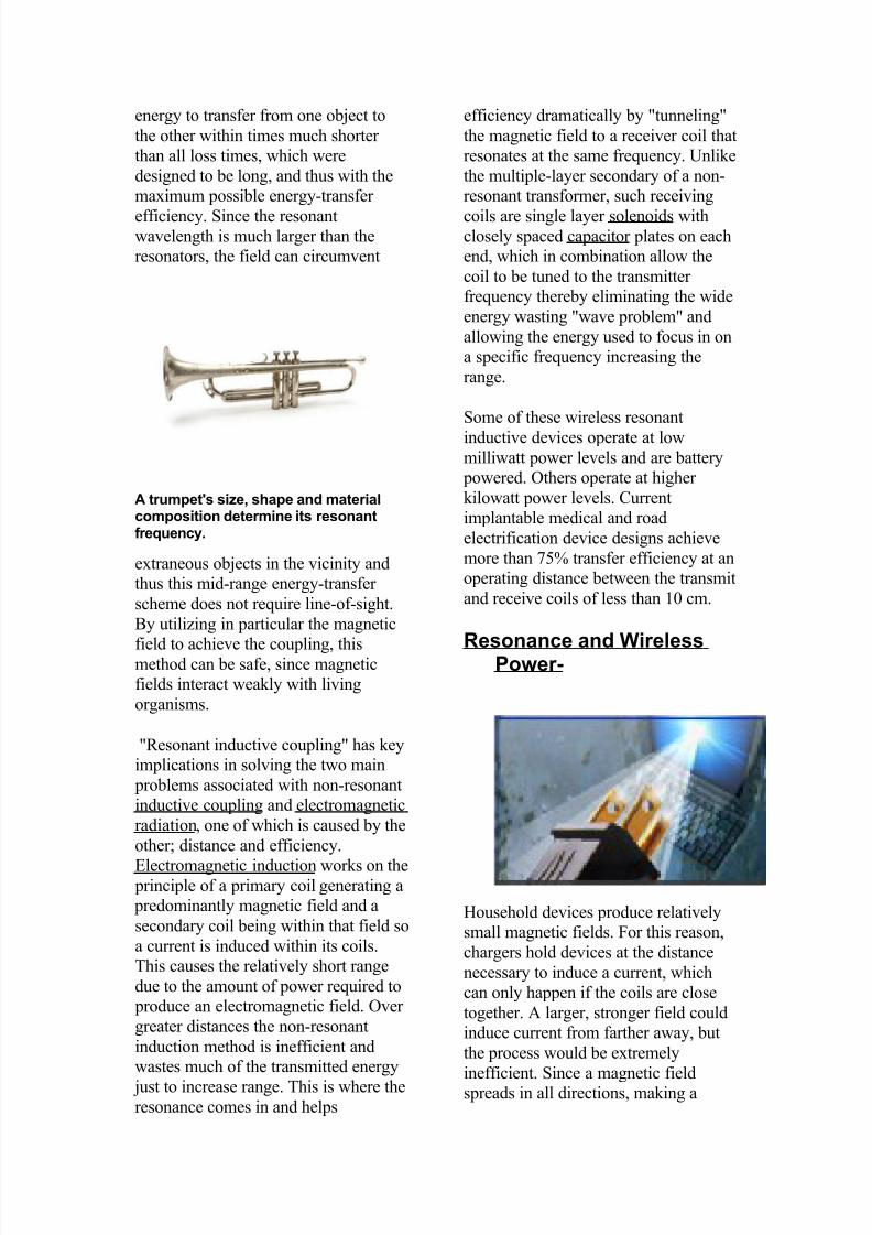
A trumpet's size, shape and materialcomposition determine its resonantfrequency.
5/14/2018 Witricity Wireless Power Transmission - slidepdf.com
http://slidepdf.com/reader/full/witricity-wireless-power-transmission-55a931a50fa8b
larger one would waste a lot of energy.
The distance between the coils can be
extended by adding resonance to the
equation.
A good way to understand resonance isto think of it in terms of sound. An
object's physical structure -- like the
size and shape of a trumpet --
determines the frequency at which it
naturally vibrates. This is its resonant
frequency. It's easy to get objects to
vibrate at their resonant frequency and
difficult to get them to vibrate at other
frequencies. This is why playing a
trumpet can cause a nearby trumpet to
begin to vibrate. Both trumpets have thesame resonant frequency.
Induction can take place a little
differently if the electromagnetic fields
around the coils resonate at the same
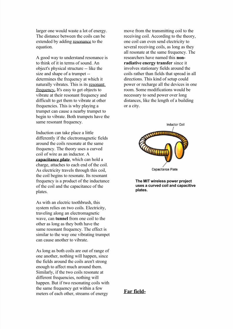
frequency. The theory uses a curved
coil of wire as an inductor. A
capacitance plate, which can hold a
charge, attaches to each end of the coil.
As electricity travels through this coil,the coil begins to resonate. Its resonant
frequency is a product of the inductance
of the coil and the capacitance of the
plates.
As with an electric toothbrush, this
system relies on two coils. Electricity,
traveling along an electromagnetic
wave, can tunnel from one coil to the
other as long as they both have the
same resonant frequency. The effect issimilar to the way one vibrating trumpet
can cause another to vibrate.
As long as both coils are out of range of
one another, nothing will happen, since
the fields around the coils aren't strong
enough to affect much around them.
Similarly, if the two coils resonate at
different frequencies, nothing will
happen. But if two resonating coils with
the same frequency get within a fewmeters of each other, streams of energy
move from the transmitting coil to the
receiving coil. According to the theory,
one coil can even send electricity to
several receiving coils, as long as they
all resonate at the same frequency. The
researchers have named this non-radiative energy transfer since it
involves stationary fields around the
coils rather than fields that spread in all
directions. This kind of setup could
power or recharge all the devices in one
room. Some modifications would be
necessary to send power over long
distances, like the length of a building
or a city.
Far field-
The MIT wireless power projectuses a curved coil and capacitiveplates.
5/14/2018 Witricity Wireless Power Transmission - slidepdf.com
http://slidepdf.com/reader/full/witricity-wireless-power-transmission-55a931a50fa8b
Means for long conductors of electricity
forming part of an electric circuit and
electrically connecting said ionized
beam to an electric circuit.These methods achieve longer ranges,
often multiple kilometre ranges, where
the distance is much greater than the
diameter of the device(s).
Radio and microwave-
Microwave power transmission
Power transmission via radio waves can
be made more directional, allowinglonger distance power beaming, with
shorter wavelengths of electromagnetic
radiation, typically in the microwave
range. A rectenna may be used to
convert the microwave energy back into
electricity. Rectenna conversion
efficiencies exceeding 95% have been
realized. Power beaming using
microwaves has been proposed for the
transmission of energy from orbiting
solar power satellites to Earth and the beaming of power to spacecraft leaving
orbit has been considered.
Power beaming by microwaves has the
difficulty that for most space
applications the required aperture sizes
are very large. These sizes can be
somewhat decreased by using shorter
wavelengths, although short
wavelengths may have difficulties with
atmospheric absorption and beam blockage by rain or water droplets.
For earthbound applications a large area
10 km diameter receiving array allows
large total power levels to be used
while operating at the low power
density suggested for human
electromagnetic exposure safety. Ahuman safe power density of 1
mW/cm2 distributed across a 10 km
diameter area corresponds to 750
megawatts total power level. This
is the power level found in many
modern electric power plants.
High power-
Wireless Power Transmission (using
microwaves) is well proven.
Experiments in the tens of kilowatts
have been performed, achieving
distances on the order of a kilometer.
Low power-
A new company, Powercast introduced
wireless power transfer technology
using RF energy; this system is
applicable for a number of devices withlow power requirements. This could
include LEDs, computer peripherals,
wireless sensors, and medical implants.
Currently, it achieves a maximum
output of 6 volts for a little over one
meter.
Laser -
With a laser beam centered on its panel
of photovoltaic cells, a lightweight
model plane makes the first flight of an
aircraft powered by a laser beam inside
5/14/2018 Witricity Wireless Power Transmission - slidepdf.com
http://slidepdf.com/reader/full/witricity-wireless-power-transmission-55a931a50fa8b
a building at NASA Marshall Space
Flight Center.
In the case of light, power can be
transmitted by converting electricity
into a laser beam that is then fired ata solar cell receiver. This is
generally known as "power beaming".
Its drawbacks are:
1. Conversion to light, such as
with a laser, is moderately
inefficient (although quantum
cascade lasers improve this)
2. Conversion back into electricity
is moderately inefficient, with
photovoltaic cells achieving
40%-50% efficiency.
3. Atmospheric absorption causes
losses.
4. As with microwave beaming,
this method requires a direct
line of sight with the target.
Electrical conduction-
Electrical energy can also betransmitted by means of electrical
currents made to flow through naturally
existing conductors, specifically the
earth, lakes and oceans, and through the
atmosphere — a natural medium that
can be made conducting if the
breakdown voltage is exceeded and the
gas becomes ionized. For example,
when a high voltage is applied across a
neon tube the gas becomes ionized and
a current passes between the twointernal electrodes. In a practical
wireless energy transmission system
using this principle, a high-power
ultraviolet beam might be used to form
a vertical ionized channel in the air
directly above the transmitter-receiver
stations. The same concept is used in
virtual lightning rods, the electrolaser
electroshock weapon and has been
proposed for disabling vehicles.
The Tesla effect- A "world
system" for "the transmission
of electrical energy without
wires" that depends upon
electrical conductivity was
proposed by Tesla. Throughlongitudinal waves, an operator
uses the Tesla effect in the
wireless transfer of energy to a
receiving device. The Tesla
effect is the application of a
type of electrical conduction
(that is, the movement of energy
through space and matter; not just the
production of voltage across a
conductor).
Tesla stated, “Instead of depending on
induction at a distance to light the tube
[... the] ideal way of lighting a hall or
room would [...] be to produce such a
condition in it that an illuminating
device could be moved and put
anywhere, and that it is lighted, no
matter where it is put and without being
electrically connected to anything. I
have been able to produce such acondition by creating in the room a
powerful, rapidly alternating
electrostatic field. For this purpose I
suspend a sheet of metal a distance
from the ceiling on insulating cords and
connect it to one terminal of the
induction coil, the other terminal being
preferably connected to the ground. An
exhausted tube may then be carried in
the hand anywhere between the sheets
or placed anywhere, even a certaindistance beyond them; it remains
always luminous.”
The Tesla effect is a type of high field
gradient between electrode plates for
wireless energy transfer.
ADVANTAGES-
• Wireless electric energy transfer
for experimentally powering
5/14/2018 Witricity Wireless Power Transmission - slidepdf.com
http://slidepdf.com/reader/full/witricity-wireless-power-transmission-55a931a50fa8b
electric automobiles and buses
is a higher power application
(>10kW) of resonant inductive
energy transfer.
• The use of wireless transfer has
been investigated for rechargingelectric automobiles in parking
spots and garages as well.
• Any low-power device, such as
a cell phone, iPod, or laptop,
could recharge automatically
simply by coming within range
of a wireless power source,
eliminating the need for
multiple cables—and perhaps
eventually, for batteries.
• With the advent of wireless
communication protocols such
as Wi-Fi or Bluetooth,
consumers are realizing that life
without physical cables is
easier, more flexible and often
less costly.
• As the population continues togrow the demand for electricity
could out space the ability to
produce it, eventually wireless
power may become a necessity
rather than just an interesting
idea.
DRAWBACKS-
• The wireless transmission of
energy is common in much of
the world. Radio waves are
energy, and people use them to
send and receive cell phone,
TV, radio and Wi-Fi signals
every day. The radio waves
spread in all directions until
they reach antennae that are
tuned to the right frequency.
This method for transferring
electrical power would be bothinefficient and dangerous.
• The main drawback to
induction, however, is the short
range. The receiver must be
very close to the transmitter or
induction unit in order to
inductively couple with it.
APPLICATIONS-
1. Researchers have outlined a
relatively simple system that could
deliver power to devices such as laptop
computers or MP3 players without
wires. The concept exploits century-old
physics and could work over distances
of many metres, the researchers said.
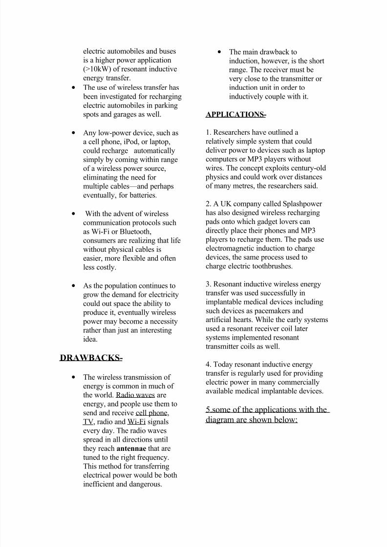
2. A UK company called Splashpower
has also designed wireless recharging
pads onto which gadget lovers can
directly place their phones and MP3
players to recharge them. The pads use
electromagnetic induction to charge
devices, the same process used to
charge electric toothbrushes.
3. Resonant inductive wireless energytransfer was used successfully in
implantable medical devices including
such devices as pacemakers and
artificial hearts. While the early systems
used a resonant receiver coil later
systems implemented resonant
transmitter coils as well.
4. Today resonant inductive energy
transfer is regularly used for providing
electric power in many commerciallyavailable medical implantable devices.
5.some of the applications with the
diagram are shown below:
5/14/2018 Witricity Wireless Power Transmission - slidepdf.com
http://slidepdf.com/reader/full/witricity-wireless-power-transmission-55a931a50fa8b
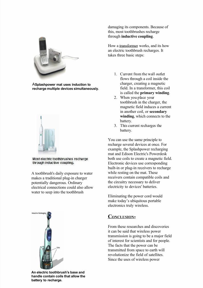
A toothbrush's daily exposure to water
makes a traditional plug-in charger
potentially dangerous. Ordinary
electrical connections could also allow
water to seep into the toothbrush
damaging its components. Because of
this, most toothbrushes recharge
through inductive coupling.
How a transformer works, and its how
an electric toothbrush recharges. Ittakes three basic steps:
1. Current from the wall outlet
flows through a coil inside the
charger, creating a magnetic
field. In a transformer, this coil
is called the primary winding.
2. When you place your
toothbrush in the charger, the
magnetic field induces a current
in another coil, or secondary
winding, which connects to the
battery.
3. This current recharges the
battery.
You can use the same principle to
recharge several devices at once. For
example, the Splashpower rechargingmat and Edison Electric's Powerdesk
both use coils to create a magnetic field.
Electronic devices use corresponding
built-in or plug-in receivers to recharge
while resting on the mat. These
receivers contain compatible coils and
the circuitry necessary to deliver
electricity to devices' batteries.
Eliminating the power cord would
make today’s ubiquitous portableelectronics truly wireless.
CONCLUSION-
From these researches and discoveries
it can be said that wireless power
transmission is going to be a major field
of interest for scientists and for people.
The facts that the power can be
transmitted from space to earth willrevolutionize the field of satellites.
Since the uses of wireless power
An electric toothbrush's base andhandle contain coils that allow thebattery to recharge.
ASplashpower mat uses induction to
recharge multiple devices simultaneously.

5/14/2018 Witricity Wireless Power Transmission - slidepdf.com
http://slidepdf.com/reader/full/witricity-wireless-power-transmission-55a931a50fa8b
transmission are many, from easy
installation, neatness, easy maintenance
to multi-equipment working are
amazing, the area for researchers on
this field seems very interesting.
Rather concentrating on the false
beliefs, the concentration should be put
on advantages of witricity for further
increasing the efficiency of wireless
power transmission with more safety
measures. It is a rocking technology
provided the researches continue to
move in same speeding direction.

![[PPT]PowerPoint Presentation - Latest Seminar Topics for ... · Web viewWhat is witricity? Witricity is nothing but wireless electricity. Transmission of electrical energy from one](https://img.pdfslide.us/doc/110x75/5aa37ed27f8b9a84398e6ccf/pptpowerpoint-presentation-latest-seminar-topics-for-viewwhat-is-witricity.jpg)