Embed Size (px)
Citation preview
IN. 1. Solids Strucrurrs Vol. 23. No. 3. pp. 369-38.5. 1987 Prinkd in Gfeal Britain.
WZO-7683187 f3.00+ .W Pqamoa Jounulr Ltd.
WITHDRAWAL OF A COMPRESSIBLE PORE FLUID FROM A POINT SINK IN AN ISOTROPIC ELASTIC
HALF SPACE WITH ANISOTROPIC PERMEABILITY
J. R. BOOKER and J. P. CARTER School of Civil and Mining Engineering, University of Sydney, Sydney, N.S.W. 2006, Australia
(Received 6 September 1985; in revised /own 25 Jamury 1986)
Abetract-The complete solution is presented for the transient etTects of pumping fluid at a constant rate from a point sink embedded in a saturated, porous elastic half space. It is assumed that the medium is homogeneous and isotropic with respect to its elastic properties and homomeous but anisotropic with respect to the flow of pate fluid. The soil skekton it mod&d as an isotropic linear elastic material obeying Hooke’s law while the pore fluid may be cornpressibk with its flow governed by Darcy’s law. The solution has ktn evaluated for a particuku value of Poisson’s ratio of the solid skeleton, i.e. 0.25, and the results have been presented graphically in the form of isochrones of excess pore pressure and surface profile for the half space. The solutions praented may have appliation in practical problems such as dewatering operations in compressible 41 and rock masses and in the extraction of petroleum products from the crust of the earth.
1. INTRODUCTION
In geotechnical, hydraulic and petroleum engineering it is sometimes necessary to pump water or some other fluid from the ground. This may be for a variety of reasons including:
(a) obtaining supplies of water, oil or gas, (b) reducing pore water pressures in the ground, (c) lowering the water table in order to allow construction operations to proceed.
In order to remove pore fluid from the ground it is necessary to reduce the pressure in the fluid in the vicinity of the pump and so there will in general be an increase in the compressive efltctive stress state. This increase of effective stress will cause consolidation of the ground and may lead to large-scale subsidence. The decrease in pore pressure will not occur immediately. After pumping has commenced the pore pressures will gradually decrease below their initial in situ values until a steady state distribution is established. Hence the resultant consolidation and surface subsidence will be time dependent.
Probably the best known examples of this phenomenon occur in Bangkok, Venice and Mexico City where widespread subsidence has been caused by withdrawal of water from aquifiers for industrial and domestic purposes. Recorded settlements in Mexico City have reached rates of 5-6cm per year[l]. However, the problem is more widespread than this with subsidence due to fluid extraction having been reported in a number of other regions of the world[2-51. The problem is not exclusively caused by the extraction of groundwater; the withdrawal of petroleum, air and gas can also induce surface subsidence[6].
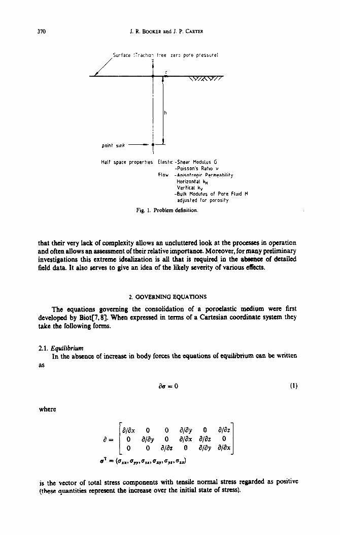
The purpose of this paper is to provide the complete solution for the transient effects of pumping fluid from a point sink embedded in a saturated porous elastic half space. The problem is ddined in Fig. 1. In obtaining this solution proper account has been taken of the coupling of the pore fluid flow with the deformation of the solid skekton. It has been assumed that the saturated medium is homogeneous with respect to its elastic properties and homogeneous but transversely isotropic with respect to the flow of pore fluid so that one value of permeability has been assumed for flow in any horizontal pIane and another value for vertical flow. Furthermore, it has been assumed that the pore fluid may be compressible and that the half space remains saturated.
The point sink problem treated here is of course an extreme idealization of any real situation. Nevertheless, it is considered that investigations of this type have much value in
369
370 J. R. BOOKER and J. P. CARTER
/
Surface ITractIon free, zero pore pressure)
T
h
point smk - t
Half space propertles Elasttc -Shear Modulus G -Poisson’s Ratio Y
Flow -Anisotropic Permeabitity Horizontal k,, Vertical kV
-Bulk Modulus of Pore FluId M adjusted for porosity
Fig. 1. Problem definition.
that their very lack of complexity allows an uncluttered look at the processes in operation and often allows an assessment of their relative importance. Moreover, for many preliminary investigations this extreme idealization is all that is required in the absence of detailed field data. It also serves to give an idea of the likely severity of various effects.
2. GOVERNING EQUATIONS
The equations governing the consolidation of a poroelastic medium were first developed by Biot[7,8]. When expressed in terms of a Cartesian coordinate system they take the following forms.
2.1. EquiliCium In the absence of increase in body forces the equations of equilibrium can be written
as
au = 0 (1)
where
a/ax 0 0 a/ay 0 ala2
a I= L 0 alay 0 a/ax a/a2 0 0 ala2 0 afay 0 I alax gg = (c u u u xx* ,y9 fZ9 xY9+, c 1 zx
is the vector of total stress components with tensile normal stress regarded as positive (these quantities represent the increase over the initial state of stress).
Withdrawal of fluid from point sink 371
2.2. Strain-displacement relations The strains are related to the displacement as follows
8 = a%
where
g = (hx, &yy* &tr* Yxy, Yyzs YZJJ
is the vector of strain components of the soil skeleton, and
UT = (4, uy, 4)
is the vector of Cartesian displacement components of the skeleton.
2.3. E&ctive stress principle It is assumed for the saturated soil that the effective stress principle is valid, i.e.
e-d-pa
(2)
(3)
where
is the vector of effective stress increments (these quantities represent the increase over the initial state of effective stress)
aT = (l,l, l,O,O,O)
and p is the excess pore fluid pressure.
2.4. Hooke’s law The constitutive behaviour of the solid phase (the skeleton) of the saturated medium
is governed by Hooke’s law, which is
u’ = De (4)
where
with 1 and G the Lame modulus and shear modulus, of the soil skeleton, respectively.
312 J. R. BOOKER and J. P. CARTER
The moduli A, G are related to Young’s modulus, E and Poisson’s ratio v of the skeleton. i.e.
Ev 1 = (1 - 2v)(l + v)
&ES 2(1 + v)
2.5. Darcy’s law It will be assumed that the flow of pore water is governed by Darcy’s law, which for
a transversely isotropic soil takes the form:
kH aP v, = --- YF ax
kH dP vY = ---
YF ay
kv ap v, = --- YF az
where kH, kV are the horizontal and vertical permeability, respectively, yF is the unit weight of pore fluid and the z coordinate direction is aligned vertically and ox, v,,, v, are the components of the superficial velocity vector relative to the soil skeleton.
2.6. Displacement equations If Hooke’s law, eqn (4), and the equation of equilibrium,
found that
where
GV2u + (A + G)V&, = Vp
eqn (l), are combined it is
(6)
is the volume strain. This equation can be condensed to give the useful relation
(A + 2G)V2s, = V2p. (7)
2.7. The volume constraint equation If the skeletal material is incompressible but the pore fluid is compressible then the
volume change of any element of soil must balance the difference between the volume of fluid leaving and entering the element by flow across its boundaries plus the volume of fluid extracted from the element by some internal sink mechanism and any change in the volume of pore fluid. Symbolically this continuity condition may be expressed as the volume constraint equation, i.e.
VTvdl+e.+-$= - qdt (8)
where q is the volume of fluid extracted per unit volume per unit time from the soil by the sink mechanism, vT = (v,, vY, v,) and M is the bulk modulus (adjusted for porosity) of the pore fluid.

Withdrawal of fluid from point sink 373
If qn (8) is combined with Darcy’s law, eqn (5), and Laplace transforms are taken of the resulting equation, we find that
or
where
c,, = k”(n + 2G)/y,
cv = k,((rl. + 2G)/y,
are the horizontal and vertical coefficients of consolidation of the saturated porous elastic medium.
The superior bar is used here to indicate a Laplace transform, i.e.
(11)
3. SOLUTION METHOD
In proceeding to the solution of the equations of consolidation for the case of a point sink embedded in a saturated elastic half space, we introduce triple Fourier transforms of the type
OD 00 JJJ
m P*k B, Y) = (1/270j e-“e‘+~y’y*)P(x,y,z)dxdydz. (12a) -m --oD --b,
The corresponding inversion formula is
m aD 00 P(x,y,s) = JJJ e’(- + UP+ yzt P*(a, j?, y) da d/3 dy.
-a -co -a
Use will also be made of double Fourier transforms of the type
4) OD eh 894 = u/w2 JJ e-yu+mp(x,y,r)dxdy -m -m
WW
uw

314 J. R. BOOKER and J. P. CARTER
and the corresponding inversion formula
eitax ’ By) P( a, /I, z) da d/I.
If we compare eqns (12) and (13) we see that
P*(a,fl,y) = & s m
e-iY’P(a,/?,z)dz -IX
and conversely
I a,
P(a,8,4 = eiyz P*(a, /I, y) dy. -m
Sometimes it will be convenient to introduce the coordinates (p,s) where
a = pcosc
/? = psin&
in which case eqns (13b) become, for polar coordinates (r, 8, z)
p(r, 64 = eiPrCos(( - “pp dp &
Quite often the transform P will be able to be represented in the form
P = cos n(tl - &)F(P, z)
(1W
(144
(14b)
(15)
(16)
(17)
and thus
p = 2x? PQP, dJ,(pr) dp (18)
where J. represents the Bessel function of order n. In the analysis which follows solutions for the equations of consolidation are found
in terms of the Laplace transforms of the triple Fourier transforms of the field quantities. Partial inversion of the triple Fourier transforms is then carried out in closed form using eqn (14) or eqn (18) and the inversion is completed using a single numerical integration. This leaves us with the Laplace transforms of the field quantities which in turn are inverted numerically using the technique developed by Talbot[9], giving the time-dependent field quantities.
The complete solution for a point source embedded in a half space is built up by first considering the case of a point sink in an infinite medium and then the case of a half space with no sink. The solutions for these problems are given in the following sections.
Withdrawal of fluid from point sink 375
4. SOLUTION FOR A POINT SINK
Let us consider a sink of strength Fk located at the point (~~,yk,zk) within an infinite medium, so that
4 = Fkb(x - xk)Gcy - yk)& - zk) (19)
where b indicates the Dirac delta function. We introduce triple transforms having the form of eqn (12a) and thus we see, for example, that the transform of q is
It will be convenient for our purposes to write this in the form
Q* = $-iY,
where
Fk - i(rh +bvk) Q=me -
4.1. Displacement equations In terms of triple transforms the displacement eqns (6) become
-GD2U* + (A + G)iaE: = iaP+ r
-GD’U,+ + (A + G)i/?E,+ = ipP*
-GD2U* + (A + G)iyEt = iyP* I
iaLJ: + i/W: + iyU: = E:
where D2 = a2 f fi2 + y2, and
(U:, U;, U:,P’, E:) = (l/2@ e-i(ux+~y+yz)(uX, u,, uZ, p, sJ dx dy dz.
Equations (22) have the solution
u: = - 0 $ E,*
U; = - 0
$ E,’
E,+
(20)
(21)
(22)
P* = (A + 2G)E:. (23)
376
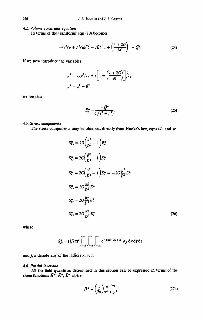
4.2. Volume constraint equation In terms of the transforms
J. R. BROKER and 1. P. CARTER
eqn (10) becomes
-(y2+ + p2C”)E: = d:[1 +(y)]+a*.
If we now introduce the variables
P’=cd,cv+s[l +(+]/L P2 = a2 + /I2
we see that
IT,* = -Q’ C”(YZ + P2)’
(24)
(25)
4.3. Stress components The stress components may be obtained directly from Hooke’s law, eqns (4), and so
E:
E:
E: = -2G$E:
S;, = 2GbE* D2 ’
where
J-.x,J-mJ-ao
and j, k denote any of the indices x, y, z.
4.4. Partial inversion AI1 the field quantities determined in this section
three functions R*, R*, L* where can be expressed in terms of the
1 e-‘Yh
jJ*= -_ 0 2n y2 + g (W

Withdrawal of fluid from point sink
R*= 1 0 e - i7Y
272 (y2 + p2p2
1
[
e - kk e - fYZ1
=2x(p2_p2) -2+ Y + P2 Y2 + P2 1
L* _ j_ iyeWiyrr
0 2n (y2 + cc2)D2
1
[
iy e - i7zt iye - itzr
= 2X(/? - p2) --
y2 + jl2 + 1 y2 *
Now for the double Fourier transforms
(R, K 9 = J ef7=(R*, R+, L)’ dy -00
and it can be shown (see Appendix) that
R = 1 e-‘* -- 2 P
R= ,,2!p2)py3q
L sgn(z, - 2) empz
= zol’_p2)[~-$J where Z = lz - zkI.
Thus on combining eqns (13a), (23), (26) and (28) we have
iCr, = - aJWlc,
iUY = -BWc,
0, = w/c,
P = -(A + 2G)RQ/c,
s xx = -2G(a’R - @Q/c,
S = -2G@R - fI@/c,
s:: = 2Gp2R(Wcv
s a)‘ = - ZGaj?RQ/c,
is,, = - 2GBWlcv
is, = - 2GaLQcv.
311
(27b)
(27~)
(2W
GW
(28~)
(29)
378 J. R. BOOKER and J. P. CARTER
5. SOLUTION FOR A HALF SPACE WITH NO SINK
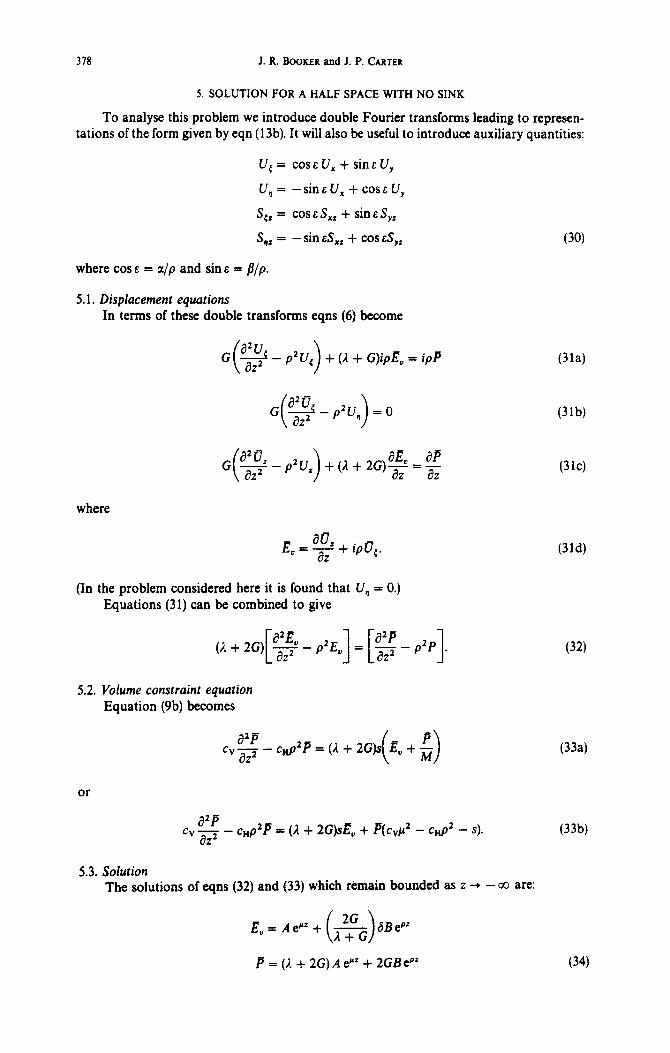
To analyse this problem we introduce double Fourier transforms leading to represen- tations of the form given by eqn (13b). It will also be useful to introduce auxiliary quantities:
U,= cossU,+sinsUy
U, = -sin&U, + cos&U,
S,, = cos E S,, + sin ES,,
S,, = -sin ES,, + cos sSys
where cos E = a/p and sins = p/p.
5.1. Displacement equations In terms of these double transforms eqns (6) become
G(g-p2U,)+(i+G)ipE.=ipP
where
(In the problem considered here it is found that U, = 0.) Equations (31) can be combined to give
5.2. Volume constraint equation Equation (9b) becomes
cv$-cHp2P=(1+2G)s E.+; ( )
(30)
Wa)
@lb)
(3W
(314
(32)
VW
or
a2B ‘” az2 - - cHp2P = (A + 2G).& + P(cvp2 - cHp2 - s). (33W
5.3. Solution The solutions of eqns (32) and (33) which remain bounded as z + - co are:
P = (I. + 2G) A eNz + 2GBePz (34)

Withdrawal of fluid from point sink
where
379
If we substitute eqns (34) into eqn (31~) we find
and thus
puz = pp ( > 2 cc Ae+=+prB(l -b)@‘+C@‘. (35)
Furthermore, it is not difficult to show that
ipI7,=(&)AP+B[($&i-(1 +pz)(l -6)k-Ce (36)
$+&&ti~+B[(&)6-l+(l -S)(l +pr)E’+CC (37)
$=(-$$)Ae’=+B[(&)d-(1 -S)(l +pr)le’VY. (38)
6. SOLUTION FOR A SINK IN A HALF SPACE
The solution to this problem can be synthesized by superimposing the solutions found in the previous sections. To do this it is convenient to introduce the following change of notation
N = S,,/2G
T = iSJ2G
U = iiJ,
w= u,.
The compkte solution for the Laplace transforms then be written in the form
(39)
of the double Fourier transforms can
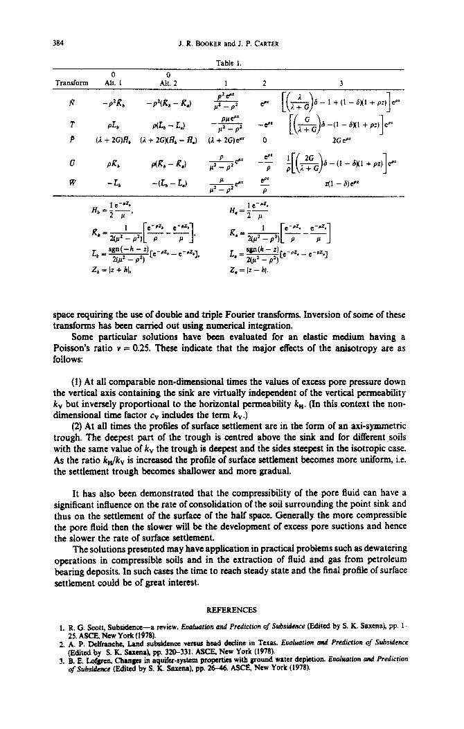
N T 1; P = u w
where the functions No, TO,. . . , W3 are specified in Table 1. The coegicknts F, , F2, F3 may be obtained from the boundary conditions, i.e. zero tractions and pore pressure at the
380 J. R. BOOKER and J. P. CARTER
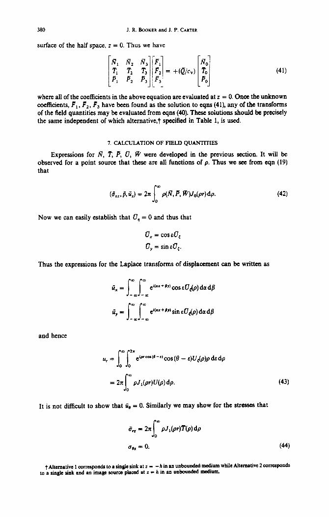
surface of the half space, z = 0. Thus we have
where all of the coefficients in the above equation are evaluated at z = 0. Once the unknown coefficients, Pi, F2, F3 have been found as the solution to eqns (41), any of the transforms of the field quantities may be evaluated from eqns (40). These solutions should be precisely the same independent of which altemative,t specified in Table 1, is used.
7. CALCULATION OF FIELD QUANTITIES
Expressions for R, ?“, P, U, ifi were developed in the previous section. It will be observed for a point source that these are all functions of p. Thus we see from eqn (19) that
(C7z,,~,n,) = 2n P@, P, W&r) dp. (42)
Now we can easily establish that or, = 0 and thus that
u, = cos EUC
27, = sin &UC.
Thus the expressions for the Laplace transforms of displacement can be written as
-- UY - eitpr +Py) sin .&&I) da d/I
and hence
co 2x
u, = H ei~rcor (8 -a cos (0 - 4 u&b de dp
0 0
= 2x PJkW(p)dp. (43)
It is not difficult to show that I& = 0. Similarly we may show for the stresses that
us2 = 0. w
t Alternative 1 corresponds to a sin& sink at z = -h in an unbounded medium while Alternative 2 corresponds to a single sink and an image source pIa& at z = h in an unbounded medium.

Withdrawal of fluid from point sink 381
v=o.25 t&/c,=1
Fig. 2. Isochroncs of excess pore pressure on the vertical axis for c&h’ = 0.1 and 03.
The single infinite integrals contained in eqns (42)-(44) have been evaluated numerically, using Gaussian quadrature.
Evaluation of the field quantities is finally achieved by inversion of the appropriate Laplace transforms. As mentioned earlier, this is also done numerically, using the efficient algorithm developed by TaIbot[9].
8. RESULTS
The solutions have been evaluated for the particular case where the soil skeleton has a Poisson’s ratio v = 0.25 and the results have been summarized in Figs 2-4. In discum@ the effects of pore fit&i compressibility it is convenient to d&e the relative compreesibiIity as M/K where M is the bulk modulus (adjusted for porosity) of the pore fiuid and K is the bulk modulus of the elastic solid skeleton, given by
KS 2(1+vlG 3(1 - 2v) *
Figure 2 shows isochrones of excess pore pressure on the vertical axis through the point sink for an isotropic soiI (cn/cv - 1) and for nondimensional t&es c$#r2 - 0.1 xnd 00. The symbol t is used here to represent the elapsed time since the mt of pumping. In all cases the changes in pore pressure due to pumping are ach&ly suctions and this is indicated by the negative values of p. When the excess pore pmssurw are

J. R. BOOKER and J. P. CARTER
;
3 c;d L P=
5
0 1 2 3 5 r/h
-0 3 v-0 25
M/K -00
-0 L -- 10 -.- 1
. . . . . . . 0 ,
-0.5
Fig. 3. Isochrones of surface settlement for the isotropic case.
normalized as indicated in Fig. 2 (i.e. using the horizontal permeability ku) the steady state response (cvr/h2 = 03) is independent of both the degree of anisotropy of permeability (i.e. k&v or c,.,/cv) and also of the degree of compressibility of the pore duid (i.e. M/K). Indeed it is possible to find a closed form expression for the excess pore pressure distribution at large time and this has been shown by the authors[lO] to be
1 1 J[r’ + Y2(z + h)2] - ,/[r* + \y2(z - /I)~] 1
where Y2 = c Jcv = k Jk,r. Along the axis r = 0, this of course reduces to
1
(45)
(46)
where the dependence on kH alone is clearly seen. At intermediate times the normalized excess pore pressures along the axis are a
function of the relative compressibility of the pore fluid M/K, as illustrated in Fig. 2 for the time corresponding to cvt/h2 = 0.1. The results show that the more compressible the pore fluid, i.e. the smaller the value of M/K, then the slower is the development of the excess pore suctions and hence the slower will be the consolidation of the soil around the sink. However, it is interesting to note that even during the transient period the isochrones of normalized excess pore pressure along the axis are practically independent of the degree of anisotropy of permeability for all cases of M/K considered, e.g. the differences between isochrone-s for c&v = 1 and 10 can hardly be plotted at the s&e shown on Fig. 2. Of course, away from the vertical axis the excess pore pressures becomemore highly dependent on the degree of anisotropy of the soil.
Typical results for displacement are indicated on Figs 3 and 4 where isochrones of surface settlement have been plotted against radial distance from the vertical axis.
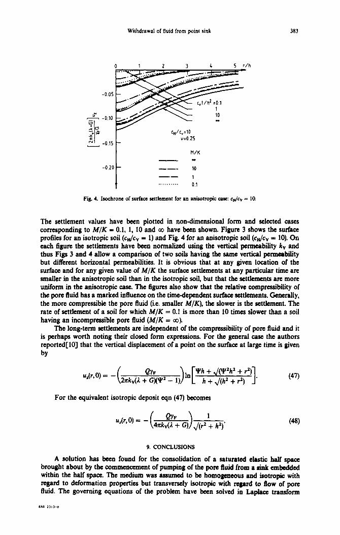
Withdrawal of fluid from point sink 383
0 1 2 3 5 r/h
v=O 25
M/K
Fig. 4. Isochrone of surface settlement for an anisotropic case: c& = 10.
The settlement values have been plotted in non-dimensional form and selected cases corresponding to M/K = 0.1, 1, 10 and co have been shown. Figure 3 shows the surface profiles for an isotropic soil (c&v = 1) and Fig 4 for an anisotropic soil (c&v = 10). On each figure the settlements have been normalized using the vertical permeability kv and thus Figs 3 and 4 allow a comparison of two soils having the same vertical permeability but different horizontal permeabilities. It is obvious that at any given location of the surface and for any given value of M/K the surface settlements at any particular time are smaller in the anisotropic soil than in the isotropic soil, but that the settlements are more uniform in the anisotropic case. The figures also show that the relative compressibility of the pore fluid has a marked influence on the time-dependent surface settlements. Generally, the more compressible the pore fluid (i.e. smaller M/K), the slower is the settlement. The rate of settlement of a soil for which M/K = 0.1 is more than 10 times slower than a soil having an incompressible pore fluid (M/K = 00).
The long-term settlements are independent of the compressibility of pore fluid and it is perhaps worth noting their closed form expressions. For the general case the authors reported[lOJ that the vertical displacement of a point on the surface at large time is given by
ukr,O) = - QYF >[ *n Yh + J(Y2h2 + r2) 2xkv@ + G)(‘P2 - 1) h + J(h2 + 9) 1
For the equivalent isotropic deposit eqn (47) becomes
‘. (47)
9. CONCLUSIONS
A solution has been found for the consolidation of a saturated elastic half space brought about by the commencement of pumping of the pore fluid from a sink embedded within the half space. The medium was assumed to be homogeneous and isotropic with regard to deformation properties but transversely isotropic with regard to flow of pore fluid. The governing equations of the problem have been solved in Laplace transform
384 J. R. BOOKER and J. P. CARTER
Table I.
0 0 Transform Ah. 1 Alt. 2 1 2 3
rJ - P2R* -p’(R,-R,) fi p* 6- 1 +(l -a)(1 -tp;) e+” 1 iab - LJ PC@’
-2 -P’ @’ P -P 1
P (2 + 2G)R, f?. + 2G)(lf, - 8,) (d + 2G)e” 0 2G P’
u P& p(R,- R.) &itri 1 P’
L* = d-h-2) _&_
2(“$ _ $) [e e_LJb], L _=@-z) -_ a 2&‘_p7p -rz,_e-‘z *I
z* = 12 + hi, 2, = Iz - 61.
space requiring the use of double and triple Fourier transfo~s. Inversion of some of these transforms has been carried out using numerical integration.
Some particular solutions have been evaluated for an eiastic medium. having a Poisson’s ratio v = 0.25. These indicate that the major elIects of the anisotropy are as follows:
(1) At all comparable nondimension times the values of excess pore pressure down the vertical axis containing the sink are virtually independent of the vertical permeability kV but inversely proportional to the horizontal permeability kH. (In this context the non- dimensional time factor cv includes the term k,.)
(2) At all times the profiles of surface settlement are in the form of an ax&symmetric trough. The deepest part of the trough is centred above the sink and for different soils with the same value of kV the trough is deepest and the sides steepest in the isotropic case. As the ratio k,Jkv is increased the profile of surface settlement becomes more unif&m, i.e. the settlement trough becomes shallower and more gradual.
It has also been demonstrated that the compressibility of the pore fluid can have a sibilant influence on the rate of inundation of the soil surrounding the point sink and thus on the settlement of the surface of the half space. Generally the more compressible the pore fluid then the slower will be the development of excess pore suctions and hence the slower the rate of surface settlement.
The solutions presented may have application in practical problems such as dewatering operations in compressible soils and in the extraction of fluid and gas from petroleum bearing deposits. In such cases the time to reach steady state and the final profile of surface settlement could be of great interest.
REFERENCES
1. R. C. Scott, Sub&ha-a review. Evhution and Prediction Q StMdence (Edited by S. K. Saxena), pp. l- 25. ASCE, New York (1978).
2. A. P. &ifmnche, Ismd subsiduxa WESUS hmd decline in Texas. Et&&on cmd Prediction of S~side~ce (Edited by S. R. Saxena), pp. 320-331. AXE, New York (1978).
3. B. E. I&&en, Changes in aquifer-system properties with~ground water depletion. Eouluation and Prediction of Subsidence (Edited by S. K. Saxena), pp. 26-46. ASCE, New York (1978).
Withdrawal of fluid from point sit& 385
4. J. Premchitt, Land subsidence in Bangkok, Thailand: results of initial investigation, 1978. Georech. Engng 10.49-76 (1979).
5. Y. Harada and T. Yamanouchi. Land subsidence in 8aga Plain, Japan and its analysis by the quasi three- dimensional aquifer model. Geotech. Engng 14,23-54 (1983).
6. J. Bear and G. F. Pinder, Porous medium deformation in multiphase flow. J. Engng Mech. Div. AK& 1@4, 881-894 (1978).
7. M. A. Biot, General theory of three dimensional consolidation. 1. Appl. Phys. 12, 155-164 (1941). 8. M. A. Biot, Consolidation scttkmmt under rnctangular load distribution. 1. Appl. Phys. lf426-430 (1941). 9. A. Talbot, The accurate numerical inversion of Laplace transforms. 1. Inst. Math. Appl. 23.97-120 (1979).
10. J. R. Booker and J. P. Carter, Long tetm subsidence due to fluid extraction from a saturated, anisotropic, elastic soil mass. Q. JI Mech. Appl. Moth. 39, 85-97 (1986).
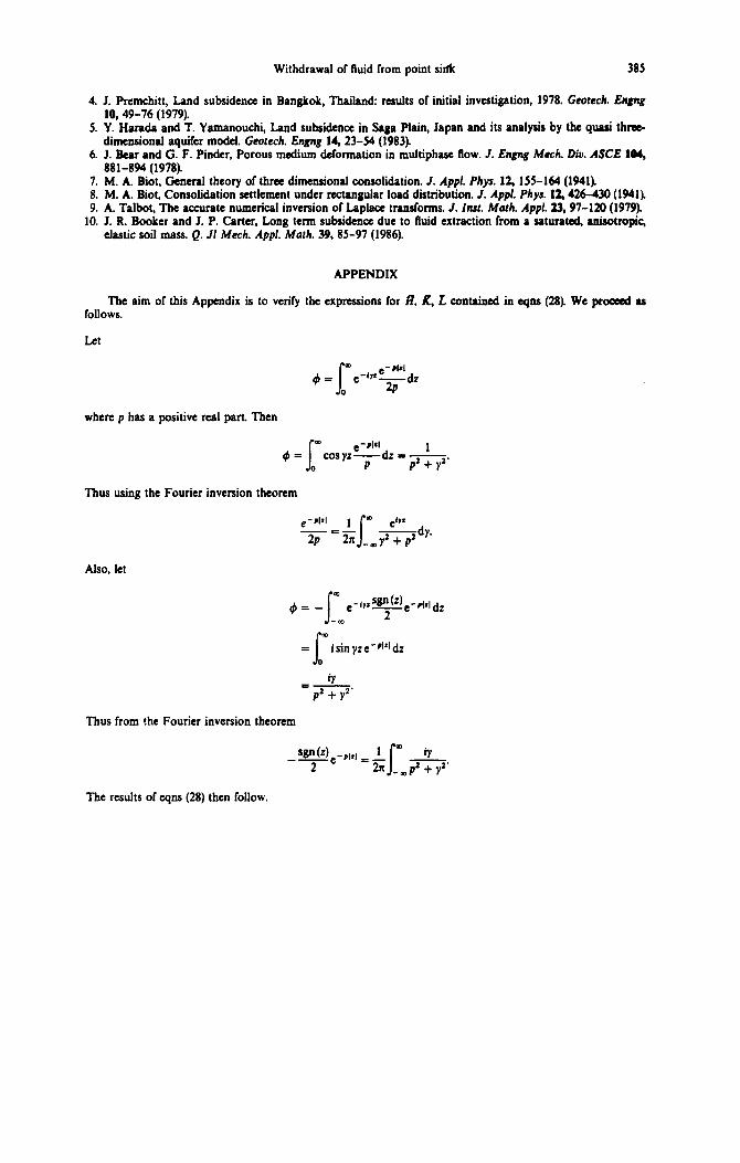
APPENDIX
The aim of this Appendix is to verify the expressions for fl, R, L contained in eqns (28). We proceed as follows.
where p has a positive real part. Then
Thus using the Fourier inversion theorem
Also, let
m 4 = _ I -PbI &
-0D
I m
= i sin yz ec’lzI dz 0
8 =-
p2 + y2’
Thus from the Fourier inversion theorem
8 4vwe-,,‘l _ 1 - 2 -5 I _,p’+
The results of cqns (28) then follow.