Embed Size (px)
Citation preview

RAISING AND MOVING THE SLAB-ON-GRADE HOUSE
WITH SLAB ATTACHED
US Army Corps of Engineers
FloodPro fi~ng~
NATIONAL FLOOD PROOFING COMMITTEE
1990

Prepared by:
Flood Control and Floodplain Management Branch Planning Di vision Galveston District, Corps of Engineers
for Corps of Engineers National Flood
Proofing Committee

TABLE OF CONTENTS
Table of Contents 1
Introduction 1
Raising and Relocation 1 Advantages 2 Disadvantages 2
The Slab-on-Grade Home 2
With Slab Attached - Some Pros & Cons 2
Methods & Techniques 2 Raising and Moving the Structure 2 Cutting the Structure 3 Time Required for the Work 4
The Steps Involved 4 Raising in Place 4 Relocation 5
Foundation Design Considerations 5
Costs Involved 6
Cost Estimates 7
Conclusions 8
A Photographic Study of Jobs in Progress 11 Preparation for installing the Lifting Beams 11 Construction of the New Foundation 20 Cutting the Structure Apart for a Move 27
TABLES
TABLE 1 - DETAILED COST ESTIMATE, ELEVATION OF A 36X36 9 (1296 SF) ONE-STORY HOME 2 FEET ABOVE GRADE
TABLE 2 - DETAILED COST ESTIMATE, ELEVATION OF A 36X36 10 (1296 SF) ONE-STORY HOME 10 FEET ABOVE GRADE

INTRODUCTION
Approximately seven percent of the land area of the United States is subject to flooding from one source or another~ Unfortunately, because of their locations near water, the areas subject to flooding have been, and continue to be, highly desirable for human habitation and development. As a result, much of the nation's population and industry is located in flood prone areas, and has suffered tremendous losses from flood damage.
Many approaches to flood protection and flood loss reduction have been developed and used with varying degrees of success, including raising existing structures above expected flood levels, or relocating them to flood free areas. Those particular approaches are relatively simple for structures originally constructed on piers; however, they are not as well recognized as economically viable practices for structures on concrete slab foundations. In the case of slab foundations, there are, however, two practical possibilities: detaching the structure from the floor slab, or moving the entire structure with the slab attached. The latter practice, moving the entire structure with the slab attached, is not widely known and understood and is often believed to be infeasible. It is, however, technically feasible, is often economically feasible, and presents many advantages in the hands of an experienced structural mover.
The purpose of this report is to discuss the procedures for raising or relocating' 'slabon-grade" structures with the slab attached, to point out some of the advantages and disadvantages, to suggest some factors to consider, and to indicate the possible costs involved. The procedures and techniques described here are based primarily on those employed by a professional structural mover currently operating in the Tampa Florida area. Other professionals in the field may employ different but
equally effective methods. No undertaking of this magnitude should be attempted without the advice and assistance of professional structural movers and structural engineers or arcitects.
RAISING AND RELOCATING
Raising a structure above expected flood levels or relocating it to a flood free area are both effective flood damage reduction measures. Both are relatively expensive however, and each has advantages and disadvantages.
In many instances a particular home site is selected for the aesthetic values provided by proximity to water, either a stream or shoreline, without recognizing the flood potential or in spite of it. In such cases, moving the home to a flood free site would not be the preferred solution even if possible. In other cases the site is relatively unimportant, but moving the structure to a new site presents insurmountable difficulties either because of the route involved, or because of the lack of an alternate site within a reasonable distance. In such cases raising the structure in place may be practical.
Some possible disadvantages to raising in place compared to relocation include: the possibility of escape routes being blocked by rising flood waters; damage and disruption to necessary utilities; the possibility of greater flood heights than designed for; the possibility of a false sense of security. The relocation of a structure has fewer disadvantages for the individual property owner, assuming a free choice to relocate or not and a reasonable selection of alternate sites. One notable disadvantage, however, is that a structure of any appreciable size must usually be separated into sections small enough for the transportation route involved, then reassembled at the
1

new location. This can be particularly difficult for structures with more than one floor or steeply pitched roofs.
Some of the advantages and disadvantages of raising in place compared to relocating are summarized as follows:
Advantages: Allows use of a desirable but flood
prone site; Avoids difficulties of restrictive
relocation routes; Avoids the necessity of cutting the
structure into sections.
Disadvantages: Escape routes may be blocked by ris
ing floodwaters; Necessary utilities may be damaged or
disrupted Flood heights may exceed those
designed for; May engender a false sense of secu
rity.
THE SLAB-ON-GRADE HOME
As mentioned earlier, there are two approaches to moving or raising the slab-ongrade structure: detaching the structure from the slab, or moving the structure with the slab attached. The fonner case has been documented in other studies and will not be discussed further in this report.:!
The lifting and moving procedures are essentially the same for the two processes. The principle differences lie in the preparation of the structure for lifting and moving, and the design of, and reattachment to, the new foundation.
WITH SLAB ATTACHED SOME PROS AND CONS
This procedure has a number of advantages over the detached-from-slab approach, but there are special considerations not present in the latter case.
In the case of raising the structure in place, or moving it only a short distance such that temporary utility connections can be maintained, a major advantage to the homeowner is the possibility of continued residence in and use of the home during the process. While recognizing that each structure will differ in architectural and structural design and must be treated on a case-by-case basis, experienced structural movers report that usually only fragile contents need be secured.
If the structure must be moved any distance, particularly in pieces, remaining in residence is of course not possible. However, the presence of the floor slab adds greatly to the structural integrity of the building or building segments during the move, and somewhat simplifies the internal shoring and bracing required. The presence of the slab is especially advantageous, if not absolutely essential, for some types of construction such as concrete block.
Advantages of this technique compared to detaching the structure from the slab can be summarized as follows: • May pennit continued occupancy and use of the structure; • A voids or simplifies interior shoring and bracing; • Applicable to some construction materials not feasible to move or raise otherwise.
2

METHODS AND TECHNIQUES desired elevation, and the new foundation is constructed beneath it. The photograph on
Raising and Moving the Structure-A system used extensively in Florida,
where construction with concrete block is widely practiced, involves excavating the soil from beneath the structure, inserting a system of two, heavy steel longitudinal beams and numerous, closely spaced cross members, and cutting the plumbing connections and any footings or piers encountered. Procedures will vary somewhat from structure to structure, and must be planned on a case-by-case basis. The slab-on-grade is typically designed to be continuously supported by the underlying soil. This demands careful planning for the systematic removal of the soil and for support of the slab throughout the process as shown in the photograph on page 16. Special care is required for concentrated loads such as fireplaces and chimneys as indicated in the photograph on page 17.
Hydraulic jacks are placed at three points beneath the steel beam system, two near one end of the structure beneath each of the main longitudinal beams, and one at the other end of the structure mid-way between the two longitudinal beams. The lifting points are thus positioned so as to form an isosceles triangle in the horizontal plane of the slab. The three-point lift minimizes the possibility of cracking of the slab due to twisting or differential movement.
If the structure is to be raised in place without relocation, once it is raised to the desired elevation the jacks are replaced with timber cribbing. If it is to be moved to another location, large wheeled dollies are inserted at the two jacking points under the main beams, and the hauling equipment takes the load at the third jacking point centered between the main beams. At the new location, the moving equipment is replaced by timber cribbing supporting the structure at the
page 22 shows one of the timber cribbing supports placed beneath a main longitudinal beam.
Cutting the Structure If piers or portions of grade beams
must be removed, they are first scored along appropriate cut lines with an air saw equipped with a concrete blade, then broken with a hammer. Photographs on page 26 show where previously existing piers have been cut away. Any reinforcing steel encountered is cut with a torch.
If the structure's size or shape prevents raising or moving it in one piece, it can be cut into manageable segments. If the structure is too tall for vertical clearances available along the route, the roof can be partially or completely removed. It is frequently necessary to remove chimneys for this reason. It may also be advantageous to remove the floor from attached garages, many of which are constructed at a slightly lower elevation than the remainder of the house.
Cuts in walls are made between studs in frame construction. In concrete block construction, a whole section of blocks may be removed, and replaced at the new site, sometimes incorporating a new pilaster at the location of the removed blocks.
Vertical cuts through roofs are usually made between rafters or joists, or immediately alongside a rafter or joist. Reconnections at cuts between rafters are made with 2x6, or 2x8 timbers laid flat against the underside of the roof. Reconnections of cuts immediately adjacent to a rafter can be made by nailing additional rafters to the old rafter.
Cuts through the slab are made with "street saws" equipped with diamond blades. Usually no attempt is made to reconnect the slab at the new site. The joints will merely be
3

sealed with grout. New foundation piers can be located directly under slab cuts to prevent differential movement of the two edges. The photograph on page 27 shows a cut through a slab prior to raising the structure.
Time Required for the Work According to experienced structural
movers, about two weeks are required for the average residential structure for initial site preparations, excavation and tunneling, and jacking. This time can be substantially increased by site conditions such as large trees preventing or limiting access by the excavating and earth moving equipment, the need for dewatering, the presence of rock, etc. Construction of the newfoundation, reconnecting utilities and air conditioning equipment, architectural adjustments, and final site cleanup and landscaping involve additional time.
Additional time would also be required if the structure is to be cut into sections, moved to a new location, and reassembled. This latter time is highly variable, depending on the design of the structure involved, distance of the move, and difficulty of the route. Speed of the equipment along the route can be as high as 20 mph under extremely favorable road conditions, but usually ranges between 3 and 8 mph.
THE STEPS INVOL VED
The following steps would generally be required, although not necessarily in the sequence presented.
Raising in Place The operations listed below assume
continued occupation of the home during the process.
and arranging with utility providers for necessary disconnections, reconnections and inspections. Requirements vary greatly from jurisdiction to jurisdiction.
2. Site work as required to allow access for necessary equipment. This would include removal and protection of trees and shrubs, removal of fences, etc.
3. Excavating around the perimeter of the slab to allow access for subsequent operations. Excavation is carried to an elevation below the base of the perimeter grade beams.
4. Excavation and tunneling under the foundation to allow placement of support beams. Excavation and tunneling are accomplished both manually and mechanically. Specialized earthmoving equipment has been developed to facilitate this process. One such piece of equipment, termed a "long nose bucket" or a "snoot" by its developer, is designed for attachment to a front end loader. The "snoot" is pushed under the slab to remove the earthen materials. Photographs of this equipment and its use are shown on pages 13 through 15.
5. Providing temporary, flexible utility connections. Water, electricity, telephone and natural gas are generally above ground connections and relatively simple. Sanitary sewer connections will generally require excavation, usually in connection with the excavation and tunneling under the slab.
6. Detaching driveways, sidewalks, porches and garage, if applicable, or removing the slabs from these areas.
7. Removing or securing fragile home furnishings. Most of the contents can remain in the home throughout the process.
1. Obtaining the necessary building permits,
4

8. Placing support beams and jacks. A system of main beams and smaller cross beams is used. The main beams are placed under the structure and positioned on jacks. The cross beams are placed over the main beams and jacked upward until close to the slab, then shimmed against the underside of the slab. Unevenness in the underside of the slab is compensated for by the shims as illustrated on page 25.
9. Elevating the structure and supporting it on temporary cribbing as shown on page 22.
10. Providing temporary access facilities to the structure. (Temporary entrance steps, landings, etc.)
11. Constructing the new foundation (see photographs on pages 19 through 23.)
12. Elevating and reconnecting the air conditioning equipment, if any.
13. Permanently reconnecting the utilities.
14. Constructing and installing architectural and aesthetic adjustments as required. This will include new entrances, and closing-in under the elevated floor slab which must give consideration to floodplain regulations such as a requirement for breakaway walls.
15. Restoring the site, including landscaping.
Relocation Relocating the structure would entail all or most of the operations required for raising in place, plus some additional procedures related to the move to a new location. Temporary utility connections are usually not required as it is generally not possible to continue living in the home during the moving process. If the structure must be moved in sections, most or
all of the contents must be removed and stored, possibly including even carpets, plumbing fixtures, water heaters, air conditioning systems, etc. With those exceptions, all of the operations are similar to raising in place. Additional operations would be required as follows.
1. Investigating possible routes to the new location, and arranging for necessary pem1its and utility company assistance along the selected route.
2. Site preparations at the new site, including installation of utility service. Timing of utility service construction must be planned to avoid damage from heavy equipment during the house moving process.
3. Cutting the structure into sections small enough for the route, placing interior shoring, and weather proofing the openings. Vertical clearance limitations may require removal of roof sections. Cut locations must be carefully chosen to minimize damage and maximize internal support. Cuts through hallways can minimi~e damage to interior walls. Cutting through roofs can be delayed until the final cut to minimize weather damage.
4. Placing the dollies and hauling equipment at the jacking points of each section, and moving them to the new location.
5. Reassembling the structure at the new site.
6. Constructing new walks and driveways.
FOUNDA TION DESIGN CONSIDERATIONS
The system described requires the use of construction materials and methods suitable for
5

the limited vertical clearance provided beneath the raised or relocated structure. Although it might be possible to move an elevated structure onto an already constructed foundation of driven piles, it would undoubtedly be extremely difficult and expensive, as would building a new foundation to fit the under surface of an existing slab prior to moving the slab into place. Attachment of the old slab to a timber pile foundation would also present difficult problems. The usual practice, therefore, is to move the structure to the desired location and elevation, and construct the new foundation beneath it. Reinforced concrete or concrete block are the most commonly used construction materials.
Other than the restrictions on materials dictated by the presence of the structure overhead, foundation design considerations would be no different than for new construction. Although intended primarily for use in coastal high hazard areas, excellent infonnation and recommendations on design of foundations for elevated structures is contained in the document Coastal Construction Manual published by the Federal Emergency Management Agency. 3 This document, published in February 1986, is the second edition of the publication originally entitled, Design and Construction Manual for Residential Buildings in Coastal High Hazard Areas (Coastal Construction Manual), published in January 1981.
The publication suggests a number of foundation types and materials suitable for construction of raised structures in coastal high hazard areas. Several of those suggested would lend themselves to construction in the restricted space beneath a raised or relocated structure. Among them are reinforced concrete or reinforced masonry unit (concrete block) piers on spread footings, or on grade beams under concrete slabs; and reinforced concrete or reinforced masonry unit shear
walls parallel to the likely direction of flow of flood waters or waves.
In any case, design of the new foundation should consider wind and wave forces, and the potential for erosion and scour. Also, in coastal high hazard areas, careful attention should be given to the connections between the new foundation and the raised slab.
The design should take into account the fact that the original slab was intended to be continuously supported on the underlying soil. Unsupported spans of floor slab should probably be limited to 10 feet or less, and piers should be spaced as required to insure integrity of the slab.
COSTS INVOL VED
1. Elevating the structure-Costs include site preparation, excava
tion and tunneling, removal of unwanted slab areas, utility disconnections (and temporary flexible connections if required), jacking and leveling, utility reconnections, and site cleanup. Infonnation from structural movers experienced with the process indicates the basic cost of these procedures would be about $12.00 per square foot of foundation area for a 1,200 to 1,800 square foot one-story residence. Costs per square foot would increase somewhat for either smaller or larger structures, and for multi-story structures. There is a practical lower limit to the time required, and therefore the cost, for initial site preparation, excavation and jacking, and for mobilization costs, all of which increase the cost per square foot for the smaller structures. Larger structures require more time and labor for the increased volume of material to be excavated. Within limits, up to 10 to 12 feet, the height the structure is to be elevated does not significantly affect the cost. Costs are affected,
6

however, by site conditions such as large trees preventing or limiting access by the excavating and earth moving equipment, the need for dewatering, the presence of rock, etc.
2. Construction ofthe new foundation, and attaching the elevated structure
Foundations for elevated residential structures can be constructed by a variety of methods, and with a variety of materials. The costs would be dependent on site conditions, materials used, and labor costs; and will differ for different regions of the country. Research conducted for the Coastal Construction Manual (1986) sampled cost data from a number of sources. Concerning those data, the manual states as follows.
"The cost infonnation presented here serves only to give the reader a general idea of the cost of coastal stonn-resistant construction. These data cannot be directly applied to estimating costs of a structure in a specific community." 4
According to the manual, the cost of reinforced concrete grade beams ranging in size from 8x16 to 24x24 inches cost from $7.70 to $27.50 per linear foot. Reinforced concrete masonry unit (concrete block) piers, typically 8x16 or 12x12 inches, could cost from $2 to $14 per linear foot including the footing. Reinforced concrete piers (12x24 inch) could cost from $14 to $48 per linear foot of elevation. 5
3. New or raised utilities, and raised air-conditioning equipment
Again according to the Coastal Construction Manual, raising the water utility costs from $4 to $8.80 per foot; the sewer utility costs $6 to $16.50 per foot; the gas
7
utility costs $4 per foot; and the electrical utility costs $3 per foot. (;
Varying pennit requirements, protection against freezing, etc. may influence costs for these items in various regions of the U.S.
4. Architectural modifications These include enclosing the area
beneath the raised floor slab (with breakaway walls if required); new entrance ways, stairs, landings, porches, and patios; new sidewalks and driveways; etc. Breakaway walls would cost about $.75 per square foot for lattice work, $1.50 to $2.00 per square foot for stud wall and plywood sheathing, and $2.70 to $3.10 per square foot for block walls.'
5. Landscaping and site restorationThese costs are highly variable.
COST ESTIMA TES
Detailed cost estimates for elevating a hypothetical residential structure in place two feet and ten feet above grade are shown in Tables 1 and 2.
The estimates assume the structure to be 36x36 feet, single story (1,296 square feet), with a detached garage. The foundation is assumed to be typical slab-on-grade with a perimeter grade beam and interior beams beneath bearing walls poured monolithically.
The new foundation consists of 14inch square reinforced concrete piers with 2foot square by 8-inch deep footings set 3'-10" below grade. The piers are 9 feet on centers both ways, for a total of 25 piers.
The project site is assumed to have no unusual or difficult soil conditions, and to have adequate clearances for equipment and operations.
The equipment required for elevating structures is highly specialized and expensive.

Major costs in the procedures described above are involved in mobilization and demobilization of this equipment. Some reductions in the cost per residence can be realized if work on more than one structure can be undertaken within a reasonably limited area and within a limited time. The sample cost estimates assign these mobilization costs to one structure.
These cost estimates were derived from various sources, primarily the Coastal Construction Manual, and Means Site Work Cost Data 1988. 8
The cost estimates reflect 1988 price levels in the Houston-Galveston area of the Texas gulf co~st. The estimates are intended only to indicate the general range of costs involved in a slab raising project for comparison with other possible flood protection measures or with new construction, and should not be used as a basis for estimates for specific projects. Costs in addition to those shown would be incurred for landscaping, and for temporary housing during the construction if the work prevented remaining in residence during the process.
CONCLUSIONS
Raising and moving a slab-on-grade structure with the slab attached is both practical and cost effective when undertaken by competent, experienced, and adequately equipped structural movers. In some cases the procedure may provide the only practical flood proofing option. Each structure will have highly individual engineering and architectural characteristics effecting economic feasibility and aesthetic desirability. Some advantages of this procedure include:
It may permit continued occupancy and use of the structure during the process; It avoids or simplifies interior shoring and bracing, and better preserves the structural integ
rity of the building; The technique is applicable to some construction materials not otherwise feasible to move or raise, such as concrete block.
This procedure deserves serious consideration as a practical non structural flood protection measure.
1. United States Water Resources Council, Floodplain Management Handbook, September, 1981, p. 20.
2. Relocation of a Large, Slab-On-Grade House from a Flood Plain to a Flood Free Site, U. S. Army Corps of Engineers, Tulsa District, 1984.
3. Coastal Construction Manual, Federal Emergency Management Agency, FEMA-55/ February 1986.
4. Coastal Construction Manual, p. F-1
5. Coastal Construction Manual, pp. F2 - F4
6. Coastal Construction Manual, p. F-6
7. Coastal Construction Manual, p. F-7
8. Means Site Work Cost Data 1988, R. S. Means Company, Inc., Kingston, MA, 1987.
8
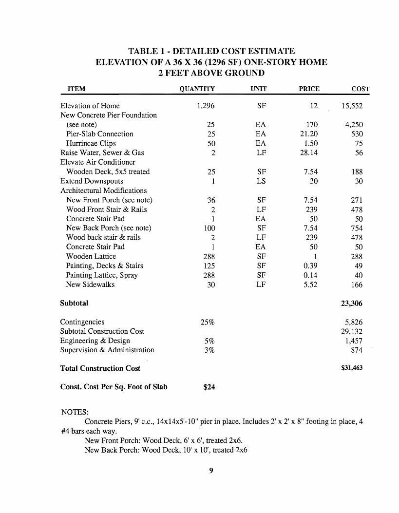
TABLE 1 • DETAILED COST ESTIMATE ELEVATION OF A 36 X 36 (1296 SF) ONE·STORY HOME
2 FEET ABOVE GROUND
ITEM QUANTITY UNIT PRICE COST
Elevation of Home New Concrete Pier Foundation
(see note) Pier-Slab Connection Hurrincae Clips
Raise Water, Sewer & Gas Elevate Air Conditioner
Wooden Deck, 5x5 treated Extend Downspouts Architectural Modifications
New Front Porch (see note) Wood Front Stair & Rails Concrete Stair Pad New Back Porch (see note) Wood back stair & rails Concrete Stair Pad Wooden Lattice Painting, Decks & Stairs Painting Lattice, Spray New Sidewalks
Subtotal
Contingencies Subtotal Construction Cost Engineering & Design Supervision & Administration
Total Construction Cost
Const. Cost Per Sq. Foot of Slab
NOTES:
1,296
25 25 50
2
25 1
36 2 1
100 2 1
288 125 288
30
25%
5% 3%
$24
SF
EA EA EA LF
SF LS
SF LF EA SF LF EA SF SF SF LF
12
170 21.20
1.50 28.14
7.54 30
7.54 239
50 7.54 239
50 1
0.39 0.14 5.52
15,552
4,250 530 75 56
188 30
271 478
50 754 478
50 288 49 40
166
23,306
5,826 29,132
1,457 874
$31,463
Concrete Piers, 9' C.c., 14x14x5'-10" pier in place. Includes 2' x 2' x 8" footing in place, 4 #4 bars each way.
New Front Porch: Wood Deck, 6' x 6', treated 2x6. New Back Porch: Wood Deck, 10' x 10', treated 2x6
9

TABLE 2 - DETAILED COST ESTIMATE ELEVATION OF A 36X36 (1296 SF) ONE-STORY HOME
10 FEET ABOVE GRADE
ITEM QUANTITY UNIT PRICE COST
Elevation of Home 1,296 SF 12 15,552 New Concrete Pier Foundation
(see note) 25 EA 190 4,750 Pier-Slab Connection 25 EA 21.20 530 Hurricane Clips 50 EA 1.50 75
Raise Water, Sewer & Gas 10 LF 28.14 281 Elevate Air Conditioner
Wooden Deck, 5 x 5, treated 25 SF 7.54 188 Extend Downspouts 1 LS 150 150 Architectural Modifications
New Front Porch (see note) 36 SF 7.54 271 Wood Front Stair & Rails 10 LF 239 2,390 Concrete Stair Pad 1 EA 50 50 New Back Porch (see note) 100 SF 7.54 754 Wood Back Stair & Rails 10 LF 239 2,390 Concrete Stair Pad 1 EA 50 50 Wooden Lattice 1,440 SF 1 1,440 Painting, Decks & Stairs. 150 SF 0.39 58 Painting Lattice, Spray 1,440 SF 0.14 202 New Sidewalks 30 LF 5.52 166
Subtotal 29,298
Contingencies 25% 7,325 Subtotal Construction Cost 36,623 Engineering & Design 5% 1,831 Supervision & Administration 3% 1,099
Total Construction Cost $39,552
Const. Cost Per Sq. Foot of Slab $31
NOTE: Concrete Piers, 9' C.c., 14' X 14' x 13' - 10" pier in place. Includes 2' x 2' x 8" footing in
place, 4 #4 bars each way. New Front Porch: Wood Deck, 6' x 6', treated 2x6. New Back Proch: Wood Deck, 10' x 10', treated 2x6.
10

A PHOTOGRAPHIC STUDY OF JOBS IN PROGRESS These photographs of actual jobs in
progress were taken at various stages in the processes described in this report at several different project sites. All of these projects are located in the Tampa-St. Petersburg area of the Florida Gulf Coast, and all were being accomplished by the firm of Masonry Movers, Inc. of Springhill, Florida.
All of the homes involved are typical residential construction for the Tampa-St. Petersburg area. Generally, their foundations consist of a reinforced concrete perimeter grade beam, in some cases supporting a concrete block foundation wall, filled with compacted soil with a floor slab poured on top. The exterior wall construction is concrete block.
The first two of the following series of photographs are intended to illustrate the techniques involved in raising a house in place. The actual jobs in progress, however, involved homes that had been moved, or were
to be moved to different sites. Only one of the projects, the second series of photographs, involved elevating the structure for flood proofing purposes; but all of the projects included tunneling, excavation, jacking, and new foundation construction.
The project in the first series of photographs involved relocation of a home from the right-of-way or a highway improvement project. It is included to illustrate the initial excavation, tunneling, and slab supporting techniques.
The second series of photographs show a home that had been moved from the beach front, and elevated to meet the floodplain regulations in force in the area. The move was necessitated by loss of land from beach erosion.
The third, and final, series of photographs illustrates the procedures involved in cutting a structure into sections for a move to a new location.
PREPARATION FOR INSTALLING THE LIFTING BEAMS
This 26-foot wide by 70-foot long house constructed of concrete block with a slab-on-grade foundation will be moved about 18 miles to another site. The structural mover, Masonry Movers, Inc., to Tampa Florida, expected to make the actual move about two days after these photographs were taken.
Site work has been accomplished to allow access for necessary equipment. This included removal or protection of trees and shrubs, removal of fences, etc. The main support beams have been off-loaded awaiting installation beneath the floor slab.
11

Excavation has beencarried out around the perimeter of the slab to an elevation below the base of the perimeter grade beams to allow access for subsequent operations.
Here, excavation and tunneling has been carried to a sufficient depth below the foundation to allow insertion of steel support beams and moving equipment.
12

Excavation and tunneling are accomplished both manually, and with specialized mechanical equipment as conditions permit.
This" long nosed" shovel, or "snoot" is designed to be attached to a front end loader, and is used to remove soil from beneath the slab.
A portion of the perimeter grade beam is being removed to facilitate insertion of the steel support beams,
13

When encountered, reinforcing steel is cut away with a cutting torc~.
The "snoot" is being used to tunnel beneath the slab. Proximity of valuable trees requires its insertion at an angle.
14

A load of excavated soil and broken concrete is removed by the "snoot" ...
... and dUDlped by raising the tip.
15

Excavation and tunneling have been carried to a sufficient depth ...
... to allow access to insertternporary supports for the slab.
16

Fireplaces and other concentrated loads require special attention to their support during the excavation process, and during placement of the lifting framework
•
A portion of the garage floor slab adhering to the chimney will fall away when the jacks are removed later and replaced with steel beam support members for the move.
17

The garage floor slab, which was at a slightly lower elevation than the rest of the house, has been removed and will be replaced at the new site.
The garage walls will be supported on steel beams inserted through these holes in the concrete block wall.
18

This concrete block home was moved several blocks in one piece, with the foundation slab attached, from a beachfront location to a site about a block back from the beach, then elevated to meet local floodplain regulations.
The space beneath' the raised structure will be enclosed for uses consistent with the floodplain regulations.
19

The eccentric weight of a wing of the house was counterbalanced with a load of concrete block.
Footings for the piers and perimeter and interior grade beams were poured after the structure was located on the site and raised to the planned elevation.
20

The piers and exterior walls have been completed to within one or two courses of the raised slab.
The exterior walls are a breakaway design as required by local floodplain regulations
21

Subsequent to elevating the structure, the structural engineer for the project decided to add a perimeter beam of reinforced concrete between the floor slab and the concrete block piers. This will require raising the structure a few additional inches to allow installation of exterior doors.
While the new foundation is being constructed, the structure is supported on cribbing placed beneath the steel framework on which it was lifted and moved.
22

The foundation for the fireplace has been partially constructed. The temporary cribbing supporting the structure is visible in the background.
The sanitary sewer connection was also cut during the tunneling and excavation operations.
23
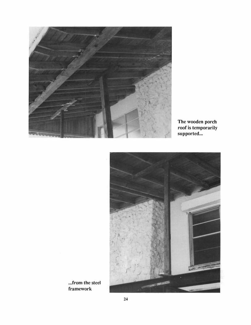
The wooden porch roof is temporarily supported...
... from the steel framework
24

Inequalities in the underside of the floor slab are accommodated by shims ...
...and wedges.
25

Piers from the original foundation, encountered during the excavation and tunneling ...
...cut away using an air saw.
26

This large home had to be moved in several sections to accomodate the restrictions of the travel route.llere the slab has been cut with a street saw.
One section of the house has been raised preparatory to inserting the wheeled dollies.
27
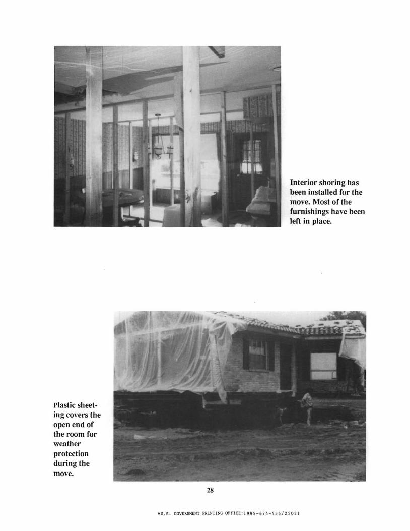
Interior shoring has been installed for the move. Most of the furnishings have been left in place.
Plastic sheeting covers the open end of the room for weather protection during the move.
28
ou.s. GOVERNMENT PRINTING OFFICE:1995-674-455/25031


![[PPT]Grillage Analysis for Slab & Pseudo-Slab Bridge Decksenggprog.com/Downloads/Lectures/BridgeEngg/Lecture No. 3... · Web viewTitle Grillage Analysis for Slab & Pseudo-Slab Bridge](https://img.pdfslide.us/doc/110x75/5adedacf7f8b9afd1a8beaa6/pptgrillage-analysis-for-slab-pseudo-slab-bridge-no-3web-viewtitle-grillage.jpg)