Embed Size (px)
Citation preview

Applications & Tools
Answers for industry.
Cover
Data Communication via ModbusTCP with S7-1200
with SIMATIC S7-1200, SENTRON PAC3200
Library Description April 2010

2 Data communication via Modbus/TCP with S7-1200
v1.0, Entry ID: 40614428
Co
pyr
igh
t
Sie
me
ns
AG
20
10
All
righ
ts r
ese
rve
d
Industry Automation and Drives Technologies Service & Support Portal This article is taken from the Service Portal of Siemens AG, Industry Automation and Drives Technologies. The following link takes you directly to the download page of this document. http://support.automation.siemens.com/WW/view/en/40614428
If you have any questions about this document, please contact us at the following e-mail address: [email protected]
Data communication via Modbus/TCP with S7-1200 v1.0, Entry ID: 40614428 3
Co
pyr
igh
t
Sie
me
ns
AG
20
10
All
righ
ts r
ese
rve
d
s
SIMATIC Data communication via Modbus/TCP with S7-1200
with SIMATIC S7-1200, Sentron PAC3200
Library Overview
1
Interface Description
2
Working with the Library
3
Links & Literature
4
History
5
Warranty and Liability
4 Data communication via Modbus/TCP with S7-1200
v1.0, Entry ID: 40614428
Co
pyr
igh
t
Sie
me
ns
AG
20
10
All
righ
ts r
ese
rve
d
Warranty and Liability Note The application examples are not binding and do not claim to be complete
regarding configuration, equipment and any eventuality. The application examples do not represent customer-specific solutions. They are only intended to provide support for typical applications. You are responsible for ensuring that the described products are used correctly. These application examples do not relieve you of the responsibility to use sound practices in application, installation, operation and maintenance. When using these Application Examples, you recognize that we cannot be made liable for any damage/claims beyond the liability clause described. We reserve the right to make changes to these Application Examples at any time without prior notice. If there are any deviations between the recommendations provided in this application example and other Siemens publications – e.g. Catalogs – the contents of the other documents have priority.
We accept no liability for information contained in this document. Any claims against us – based on whatever legal reason – resulting from the use of the examples, information, programs, engineering and performance data etc., described in this Application Example shall be excluded. Such an exclusion shall not apply in the case of mandatory liability, e.g. under the German Product Liability Act (“Produkthaftungsgesetz”), in case of intent, gross negligence, or injury of life, body or health, guarantee for the quality of a product, fraudulent concealment of a deficiency or breach of a condition which goes to the root of the contract (“wesentliche Vertragspflichten”). However, claims arising from a breach of a condition which goes to the root of the contract shall be limited to the foreseeable damage which is intrinsic to the contract, unless caused by intent or gross negligence or based on mandatory liability for injury of life, body or health. The above provisions do not imply a change in the burden of proof to your detriment.
It is not permissible to transfer or copy these Application Examples or excerpts thereof without express authorization from Siemens Industry Sector.
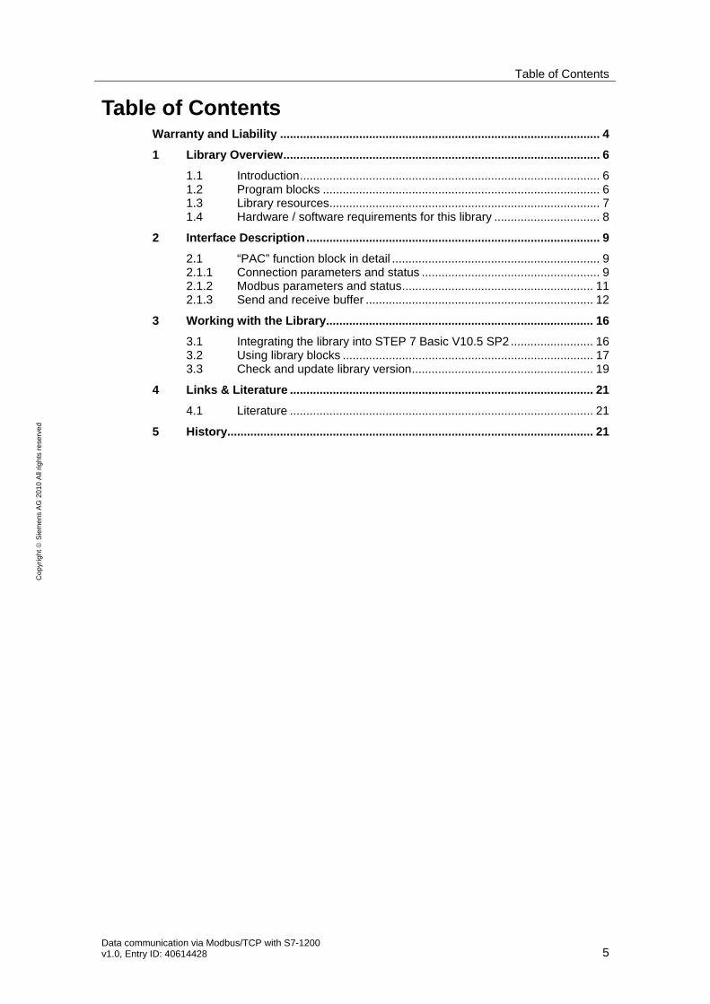
Table of Contents
Data communication via Modbus/TCP with S7-1200 v1.0, Entry ID: 40614428 5
Co
pyr
igh
t
Sie
me
ns
AG
20
10
All
righ
ts r
ese
rve
d
Table of Contents Warranty and Liability ................................................................................................. 4 1 Library Overview................................................................................................ 6
1.1 Introduction........................................................................................... 6 1.2 Program blocks .................................................................................... 6 1.3 Library resources.................................................................................. 7 1.4 Hardware / software requirements for this library ................................ 8
2 Interface Description......................................................................................... 9 2.1 “PAC” function block in detail ............................................................... 9 2.1.1 Connection parameters and status ...................................................... 9 2.1.2 Modbus parameters and status.......................................................... 11 2.1.3 Send and receive buffer ..................................................................... 12
3 Working with the Library................................................................................. 16 3.1 Integrating the library into STEP 7 Basic V10.5 SP2 ......................... 16 3.2 Using library blocks ............................................................................ 17 3.3 Check and update library version....................................................... 19
4 Links & Literature ............................................................................................ 21 4.1 Literature ............................................................................................ 21
5 History............................................................................................................... 21
1 Library Overview
6 Data communication via Modbus/TCP with S7-1200
v1.0, Entry ID: 40614428
Co
pyr
igh
t
Sie
me
ns
AG
20
10
All
righ
ts r
ese
rve
d
1 Library Overview
1.1 Introduction
With the Modbus/TCP protocol data can be exchanged between one or several Modbus/TCP devices using an Ethernet connection. This document describes the data exchange of an S7-1200 controller with one or several SENTRON PAC3200 type Power Management Devices based on the Modbus/TCP protocol. Recommended accompanying literature are the documents and links in Table 4-1.
Figure 1-1
Modbus on TCP
1.2 Program blocks
Table 1-1
Library Element Content
PAC_FB [v1.0] Function block FB500
PAC_Tags PLC tags
PAC_TxRx_Buffer Global data block DB502 (optional send and receive block)
PAC_ModbusTCP_Client
PAC_Watch Tables Monitoring tables for send / receive buffer
When calling the function block “PAC” an instance data block is created. It is recommended to assign the name “PAC_DB” for the instance data block to be able to use the monitoring table described below. To create and maintain the communication via the Modbus/TCP protocol the “PAC” function block must be called cyclically in OB1.
The PLC tags contain necessary system memory bits and clock memory bits in memory byte 0 and 1. These must be activated in the hardware configuration of the CPU (see chapter 3.2). Furthermore prefabricated tags for switching the function block are contained in the library.
1 Library Overview
Data communication via Modbus/TCP with S7-1200 v1.0, Entry ID: 40614428 7
Co
pyr
igh
t
Sie
me
ns
AG
20
10
All
righ
ts r
ese
rve
d
The symbolically created global data block “PAC_TxRx_Buffer” can be used optionally. It is adapted especially to the application examples of PAC3200. The data block contains three arrays with different data types for receiving data and an array for filing the data to be sent.
Using the monitoring tables the function block can be operated and the send/receive buffer be monitored.
1.3 Library resources
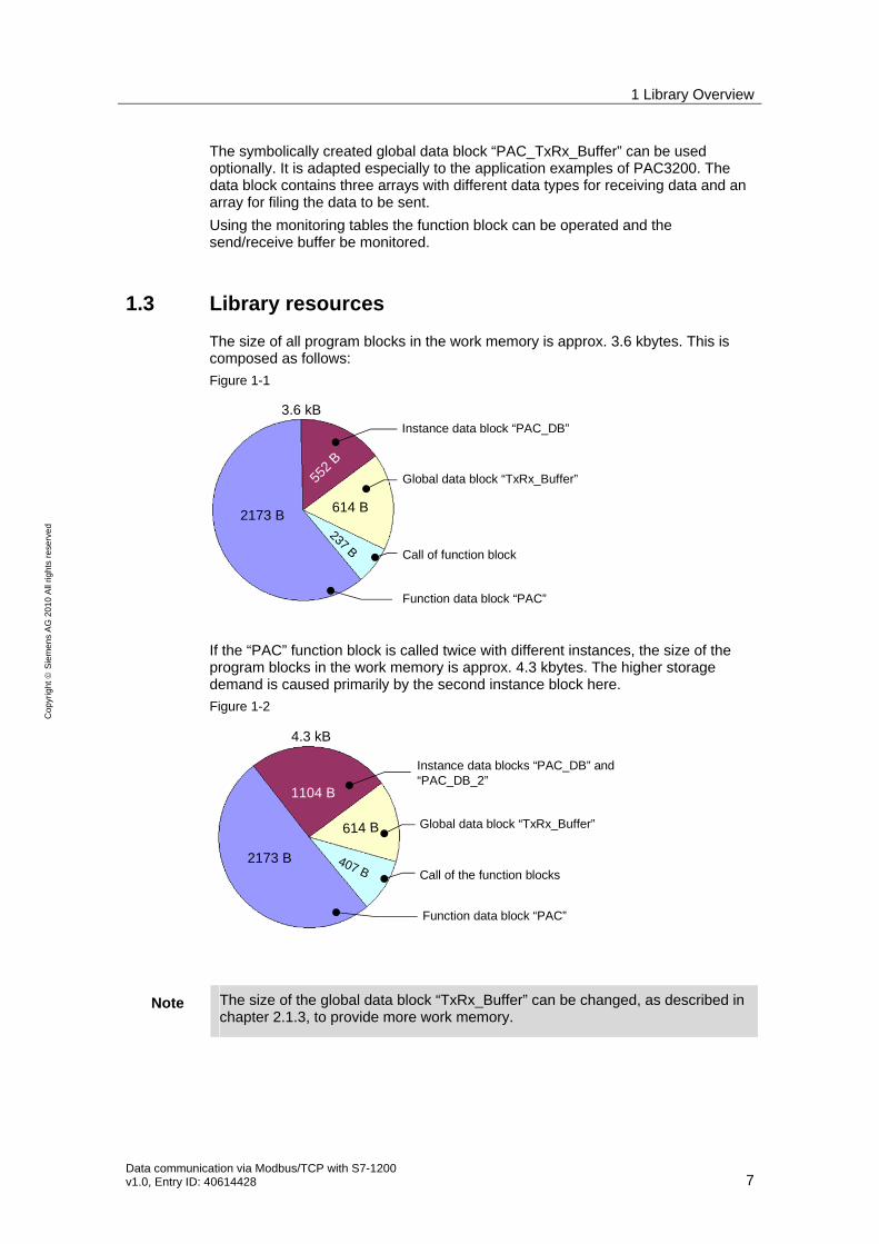
The size of all program blocks in the work memory is approx. 3.6 kbytes. This is composed as follows:
Figure 1-1
3.6 kB
2173 B
552
B
614 B
237 B
Instance data block “PAC_DB”
Global data block “TxRx_Buffer”
Call of function block
Function data block “PAC”
If the “PAC” function block is called twice with different instances, the size of the program blocks in the work memory is approx. 4.3 kbytes. The higher storage demand is caused primarily by the second instance block here.
Figure 1-2
4.3 kB
2173 B
1104 B
614 B
407 B
Instance data blocks “PAC_DB” and“PAC_DB_2”
Global data block “TxRx_Buffer”
Call of the function blocks
Function data block “PAC”
Note The size of the global data block “TxRx_Buffer” can be changed, as described in chapter 2.1.3, to provide more work memory.
1 Library Overview
8 Data communication via Modbus/TCP with S7-1200
v1.0, Entry ID: 40614428
Co
pyr
igh
t
Sie
me
ns
AG
20
10
All
righ
ts r
ese
rve
d
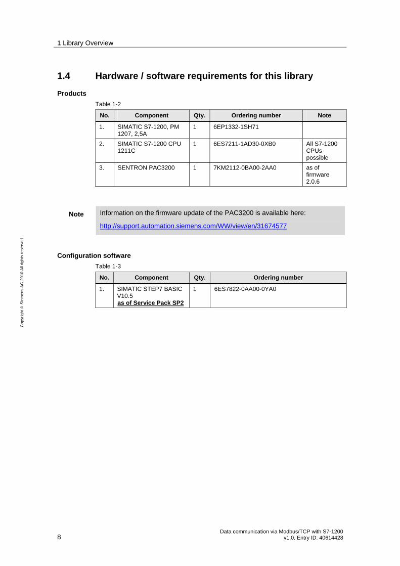
1.4 Hardware / software requirements for this library
Products
Table 1-2
No. Component Qty. Ordering number Note
1. SIMATIC S7-1200, PM 1207, 2,5A
1 6EP1332-1SH71
2. SIMATIC S7-1200 CPU 1211C
1 6ES7211-1AD30-0XB0 All S7-1200 CPUs possible
3. SENTRON PAC3200 1 7KM2112-0BA00-2AA0 as of firmware 2.0.6
Note Information on the firmware update of the PAC3200 is available here:
http://support.automation.siemens.com/WW/view/en/31674577
Configuration software
Table 1-3
No. Component Qty. Ordering number
1. SIMATIC STEP7 BASIC V10.5 Uas of Service Pack SP2
1 U6ES7822-0AA00-0YA0
2 Interface Description
Data communication via Modbus/TCP with S7-1200 v1.0, Entry ID: 40614428 9
Co
pyr
igh
t
Sie
me
ns
AG
20
10
All
righ
ts r
ese
rve
d
2 Interface Description
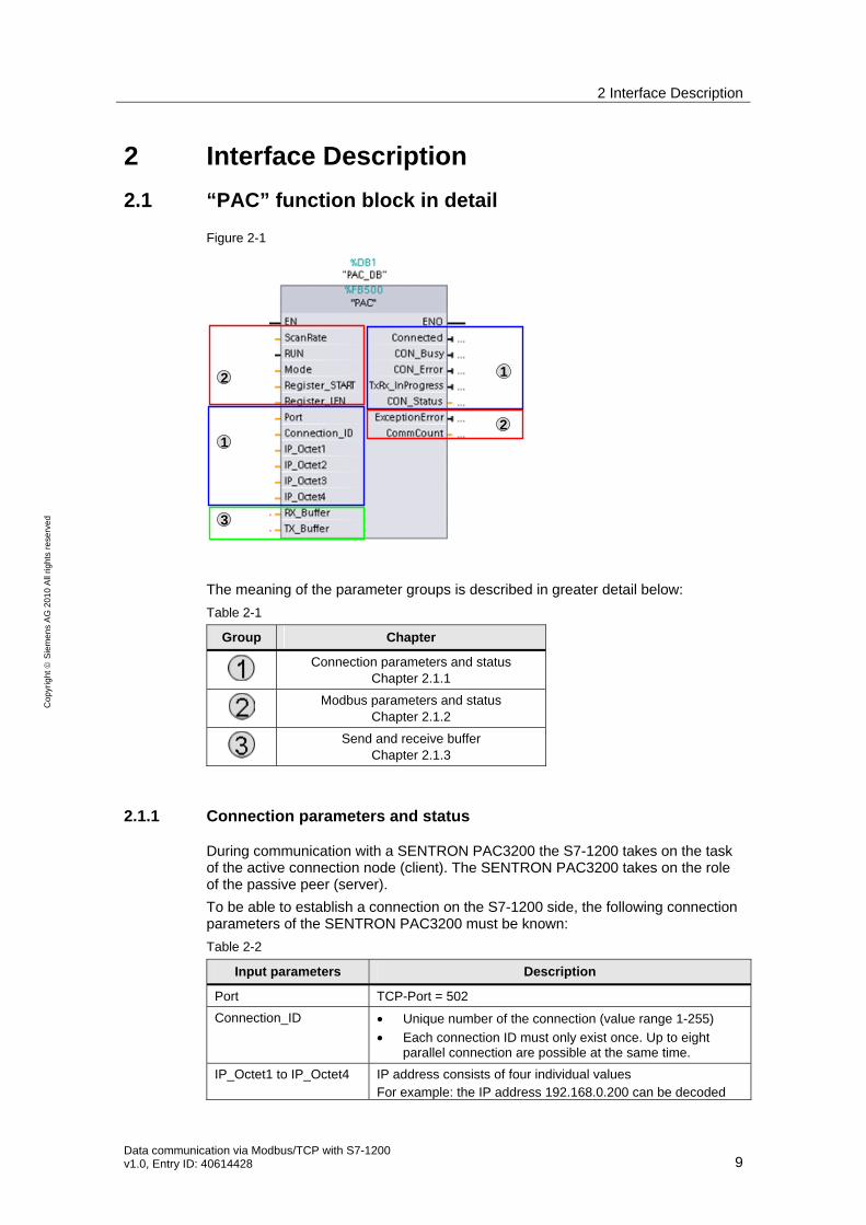
2.1 “PAC” function block in detail
Figure 2-1
1
2
3
1
2
The meaning of the parameter groups is described in greater detail below:
Table 2-1
Group Chapter
Connection parameters and status
Chapter 2.1.1
Modbus parameters and status
Chapter 2.1.2
Send and receive buffer
Chapter 2.1.3
2.1.1 Connection parameters and status
During communication with a SENTRON PAC3200 the S7-1200 takes on the task of the active connection node (client). The SENTRON PAC3200 takes on the role of the passive peer (server).
To be able to establish a connection on the S7-1200 side, the following connection parameters of the SENTRON PAC3200 must be known:
Table 2-2
Input parameters Description
Port TCP-Port = 502
Connection_ID • Unique number of the connection (value range 1-255)
• Each connection ID must only exist once. Up to eight parallel connection are possible at the same time.
IP_Octet1 to IP_Octet4 IP address consists of four individual values For example: the IP address 192.168.0.200 can be decoded
2 Interface Description
10 Data communication via Modbus/TCP with S7-1200
v1.0, Entry ID: 40614428
Co
pyr
igh
t
Sie
me
ns
AG
20
10
All
righ
ts r
ese
rve
d
Input parameters Description
as follows:
• Octet1: 192
• Octet2: 168
• Octet3: 0
• Octet4: 200
If the function block “PAC” is only called once, a connection is active and “1” can be entered for the “Connection_ID”.
If two devices communicate simultaneously, the function block must be called twice with an own respective instance. The IDs of the connection can be selected differently (e.g. 1 and 2).
Note The connection parameters:
• Connection_ID
• Port
• IP address
Can only be changed in the inactive state of the “PAC” function block.
Changes during execution of the block are ignored.
The following output parameters of the “PAC” function block give the status of the connection.
Table 2-3
Output parameters Description
Connected TRUE, if the connection was established active and successful
CON_Busy TRUE, if established connection is active If the output is pending longer, it is possible that the connection partner cannot be found. Possible causes:
• wrong IP address
• connection peer switched off
• Ethernet cable defective or unplugged
CON_Error TRUE, if an error has occurred (see CON_STATUS)
CON_STATUS Error and status information (see S7-1200 manual chapter 6.2.5.1)
TxRx_InProgress TRUE, if send or receive job is active
Note A damaged or unplugged Ethernet cable causes a disrupted connection. In this case CON_Busy is pending permanently and CON_STATUS contains the status code 7002.
If the cable is plugged in here again, the connection is established automatically after approx. 120 seconds.
Prerequisite here is at least the firmware version v2.0.6 in SENTRON PAC 3200.
2 Interface Description
Data communication via Modbus/TCP with S7-1200 v1.0, Entry ID: 40614428 11
Co
pyr
igh
t
Sie
me
ns
AG
20
10
All
righ
ts r
ese
rve
d
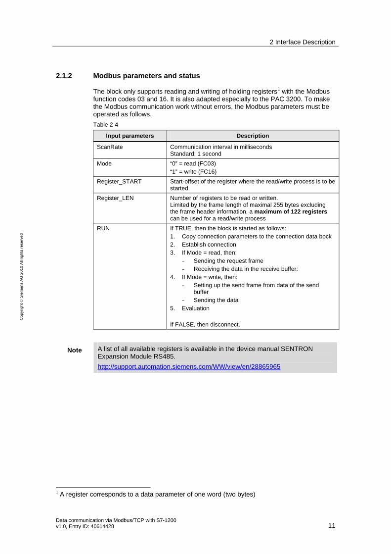
2.1.2 Modbus parameters and status
The block only supports reading and writing of holding registers1 with the Modbus function codes 03 and 16. It is also adapted especially to the PAC 3200. To make the Modbus communication work without errors, the Modbus parameters must be operated as follows.
Table 2-4
Input parameters Description
ScanRate Communication interval in milliseconds Standard: 1 second
Mode “0” = read (FC03) “1” = write (FC16)
Register_START Start-offset of the register where the read/write process is to be started
Register_LEN Number of registers to be read or written. Limited by the frame length of maximal 255 bytes excluding the frame header information, a maximum of 122 registers can be used for a read/write process
RUN If TRUE, then the block is started as follows: 1. Copy connection parameters to the connection data bock 2. Establish connection 3. If Mode = read, then:
– Sending the request frame – Receiving the data in the receive buffer:
4. If Mode = write, then: – Setting up the send frame from data of the send
buffer – Sending the data
5. Evaluation If FALSE, then disconnect.
Note A list of all available registers is available in the device manual SENTRON Expansion Module RS485.
http://support.automation.siemens.com/WW/view/en/28865965
1 A register corresponds to a data parameter of one word (two bytes)
2 Interface Description
12 Data communication via Modbus/TCP with S7-1200
v1.0, Entry ID: 40614428
Co
pyr
igh
t
Sie
me
ns
AG
20
10
All
righ
ts r
ese
rve
d
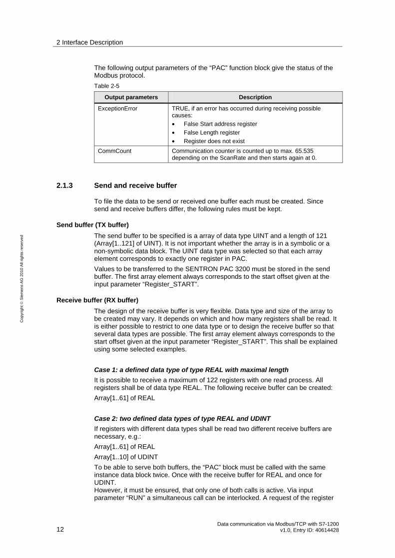
The following output parameters of the “PAC” function block give the status of the Modbus protocol.
Table 2-5
Output parameters Description
ExceptionError TRUE, if an error has occurred during receiving possible causes:
• False Start address register
• False Length register
• Register does not exist
CommCount Communication counter is counted up to max. 65.535 depending on the ScanRate and then starts again at 0.
2.1.3 Send and receive buffer
To file the data to be send or received one buffer each must be created. Since send and receive buffers differ, the following rules must be kept.
Send buffer (TX buffer)
The send buffer to be specified is a array of data type UINT and a length of 121 (Array[1..121] of UINT). It is not important whether the array is in a symbolic or a non-symbolic data block. The UINT data type was selected so that each array element corresponds to exactly one register in PAC.
Values to be transferred to the SENTRON PAC 3200 must be stored in the send buffer. The first array element always corresponds to the start offset given at the input parameter “Register_START”.
Receive buffer (RX buffer)
The design of the receive buffer is very flexible. Data type and size of the array to be created may vary. It depends on which and how many registers shall be read. It is either possible to restrict to one data type or to design the receive buffer so that several data types are possible. The first array element always corresponds to the start offset given at the input parameter “Register_START”. This shall be explained using some selected examples.
Case 1: a defined data type of type REAL with maximal length
It is possible to receive a maximum of 122 registers with one read process. All registers shall be of data type REAL. The following receive buffer can be created:
Array[1..61] of REAL
Case 2: two defined data types of type REAL and UDINT
If registers with different data types shall be read two different receive buffers are necessary, e.g.:
Array[1..61] of REAL
Array[1..10] of UDINT
To be able to serve both buffers, the “PAC” block must be called with the same instance data block twice. Once with the receive buffer for REAL and once for UDINT. However, it must be ensured, that only one of both calls is active. Via input parameter “RUN” a simultaneous call can be interlocked. A request of the register
2 Interface Description
Data communication via Modbus/TCP with S7-1200 v1.0, Entry ID: 40614428 13
Co
pyr
igh
t
Sie
me
ns
AG
20
10
All
righ
ts r
ese
rve
d
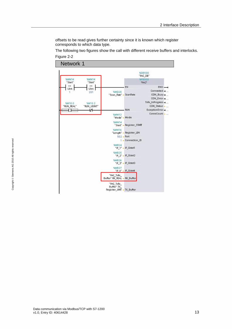
offsets to be read gives further certainty since it is known which register corresponds to which data type.
The following two figures show the call with different receive buffers and interlocks.
Figure 2-2
Network 1
2 Interface Description
14 Data communication via Modbus/TCP with S7-1200
v1.0, Entry ID: 40614428
Co
pyr
igh
t
Sie
me
ns
AG
20
10
All
righ
ts r
ese
rve
d
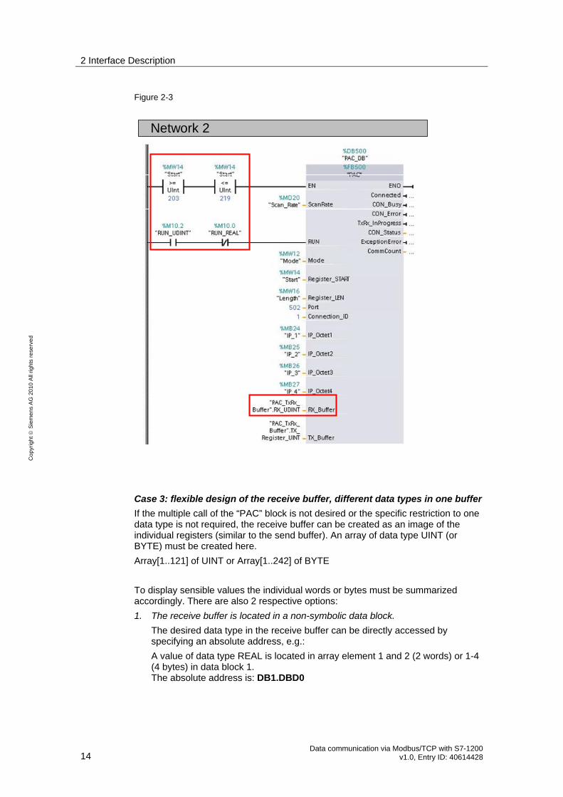
Figure 2-3
Network 2
Case 3: flexible design of the receive buffer, different data types in one buffer
If the multiple call of the “PAC” block is not desired or the specific restriction to one data type is not required, the receive buffer can be created as an image of the individual registers (similar to the send buffer). An array of data type UINT (or BYTE) must be created here.
Array[1..121] of UINT or Array[1..242] of BYTE
To display sensible values the individual words or bytes must be summarized accordingly. There are also 2 respective options:
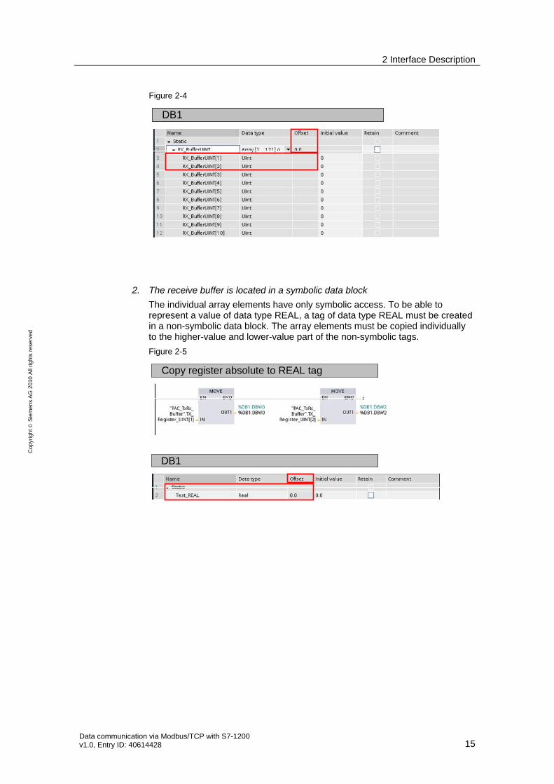
1. The receive buffer is located in a non-symbolic data block.
The desired data type in the receive buffer can be directly accessed by specifying an absolute address, e.g.:
A value of data type REAL is located in array element 1 and 2 (2 words) or 1-4 (4 bytes) in data block 1. The absolute address is: DB1.DBD0
2 Interface Description
Data communication via Modbus/TCP with S7-1200 v1.0, Entry ID: 40614428 15
Co
pyr
igh
t
Sie
me
ns
AG
20
10
All
righ
ts r
ese
rve
d
Figure 2-4
DB1
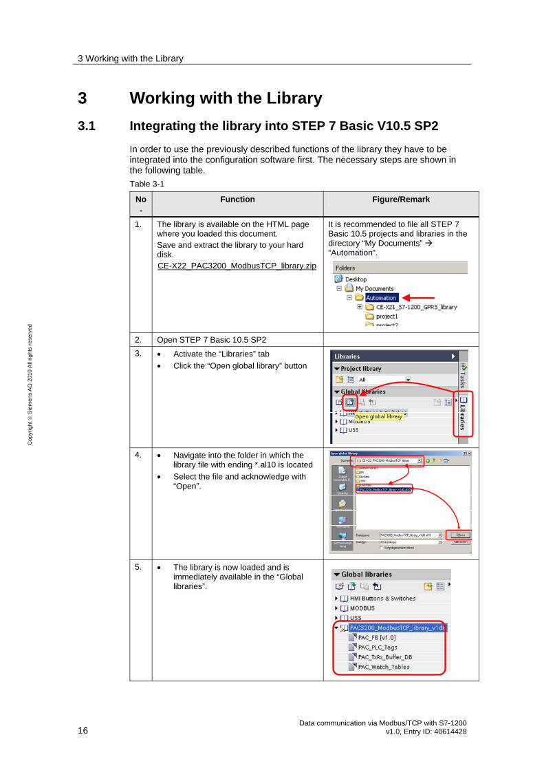
2. The receive buffer is located in a symbolic data block
The individual array elements have only symbolic access. To be able to represent a value of data type REAL, a tag of data type REAL must be created in a non-symbolic data block. The array elements must be copied individually to the higher-value and lower-value part of the non-symbolic tags.
Figure 2-5
Copy register absolute to REAL tag
DB1
3 Working with the Library
16 Data communication via Modbus/TCP with S7-1200
v1.0, Entry ID: 40614428
Co
pyr
igh
t
Sie
me
ns
AG
20
10
All
righ
ts r
ese
rve
d
3 Working with the Library
3.1 Integrating the library into STEP 7 Basic V10.5 SP2
In order to use the previously described functions of the library they have to be integrated into the configuration software first. The necessary steps are shown in the following table.
Table 3-1
No.
Function Figure/Remark
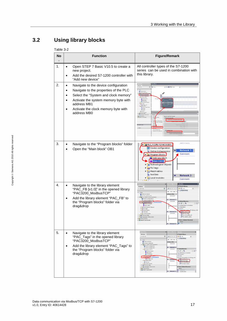
1. The library is available on the HTML page where you loaded this document. Save and extract the library to your hard disk. UCE-X22_PAC3200_ModbusTCP_library.zipU
It is recommended to file all STEP 7 Basic 10.5 projects and libraries in the directory “My Documents” “Automation”.
2. Open STEP 7 Basic 10.5 SP2
3. • Activate the “Libraries” tab
• Click the “Open global library” button
4. • Navigate into the folder in which the library file with ending *.al10 is located
• Select the file and acknowledge with “Open”.
5. • The library is now loaded and is immediately available in the “Global libraries”.
3 Working with the Library
Data communication via Modbus/TCP with S7-1200 v1.0, Entry ID: 40614428 17
Co
pyr
igh
t
Sie
me
ns
AG
20
10
All
righ
ts r
ese
rve
d
3.2 Using library blocks
Table 3-2
No.
Function Figure/Remark
1. • Open STEP 7 Basic V10.5 to create a new project.
• Add the desired S7-1200 controller with “Add new device”
All controller types of the S7-1200 series can be used in combination with this library.
2. • Navigate to the device configuration
• Navigate to the properties of the PLC
• Select the “System and clock memory”
• Activate the system memory byte with address MB1
• Activate the clock memory byte with address MB0
3. • Navigate to the “Program blocks” folder
• Open the “Main block” OB1
4. • Navigate to the library element “PAC_FB [v1.0]” in the opened library “PAC3200_ModbusTCP”
• Add the library element “PAC_FB” to the “Program blocks” folder via drag&drop
5. • Navigate to the library element “PAC_Tags” in the opened library “PAC3200_ModbusTCP”
• Add the library element “PAC_Tags” to the “Program blocks” folder via drag&drop
3 Working with the Library
18 Data communication via Modbus/TCP with S7-1200
v1.0, Entry ID: 40614428
Co
pyr
igh
t
Sie
me
ns
AG
20
10
All
righ
ts r
ese
rve
d
No.
Function Figure/Remark
6. • Navigate to the library element “PAC_Watch_Tables” in the opened library “PAC3200_ModbusTCP”
• Add the library element “PAC_Watch_Tables” to the “Watch tables” folder via drag&drop
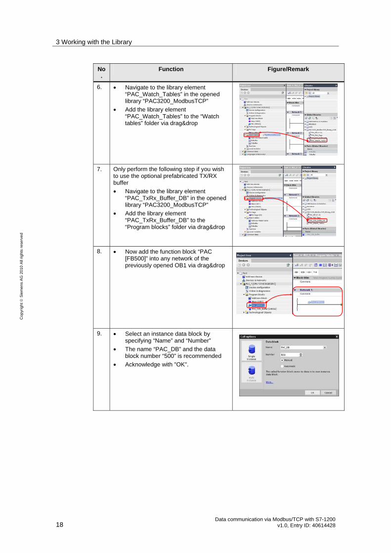
7. Only perform the following step if you wish to use the optional prefabricated TX/RX buffer
• Navigate to the library element “PAC_TxRx_Buffer_DB” in the opened library “PAC3200_ModbusTCP”
• Add the library element “PAC_TxRx_Buffer_DB” to the “Program blocks” folder via drag&drop
8. • Now add the function block “PAC [FB500]” into any network of the previously opened OB1 via drag&drop
9. • Select an instance data block by specifying “Name” and “Number”
• The name “PAC_DB” and the data block number “500” is recommended
• Acknowledge with "OK".
3 Working with the Library
Data communication via Modbus/TCP with S7-1200 v1.0, Entry ID: 40614428 19
Co
pyr
igh
t
Sie
me
ns
AG
20
10
All
righ
ts r
ese
rve
d
No.
Function Figure/Remark
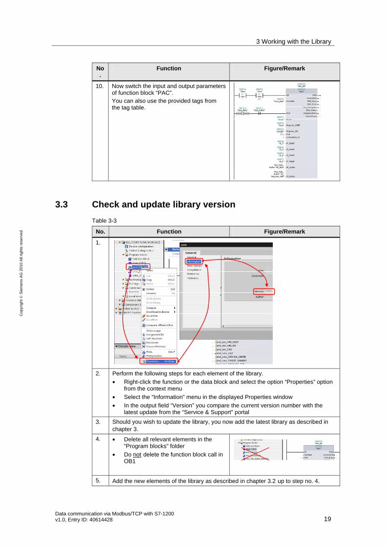
10. Now switch the input and output parameters of function block “PAC”. You can also use the provided tags from the tag table.
3.3 Check and update library version
Table 3-3
No. Function Figure/Remark
1.
2. Perform the following steps for each element of the library.
• Right-click the function or the data block and select the option “Properties” option from the context menu
• Select the “Information” menu in the displayed Properties window
• In the output field “Version” you compare the current version number with the latest update from the “Service & Support” portal
3. Should you wish to update the library, you now add the latest library as described in chapter 3 .
4. • Delete all relevant elements in the “Program blocks” folder
• Do notU delete the function block call in OB1
5. Add the new elements of the library as described in chapter 3.2X up to step no. 4.
3 Working with the Library
20 Data communication via Modbus/TCP with S7-1200
v1.0, Entry ID: 40614428
Co
pyr
igh
t
Sie
me
ns
AG
20
10
All
righ
ts r
ese
rve
d
No. Function Figure/Remark
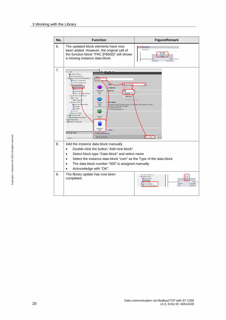
6. The updated block elements have now been added. However, the original call of the function block “PAC [FB500]” still shows a missing instance data block.
7.
8. Add the instance data block manually
• Double-click the button “Add new block”.
• Select block type “Data block” and select name
• Select the instance data block “com” as the Type of the data block
• The data block number “500” is assigned manually
• Acknowledge with "OK".
9. The library update has now been completed.
4 Links & Literature
Data communication via Modbus/TCP with S7-1200 v1.0, Entry ID: 40614428 21
Co
pyr
igh
t
Sie
me
ns
AG
20
10
All
righ
ts r
ese
rve
d
4 Links & Literature
4.1 Literature
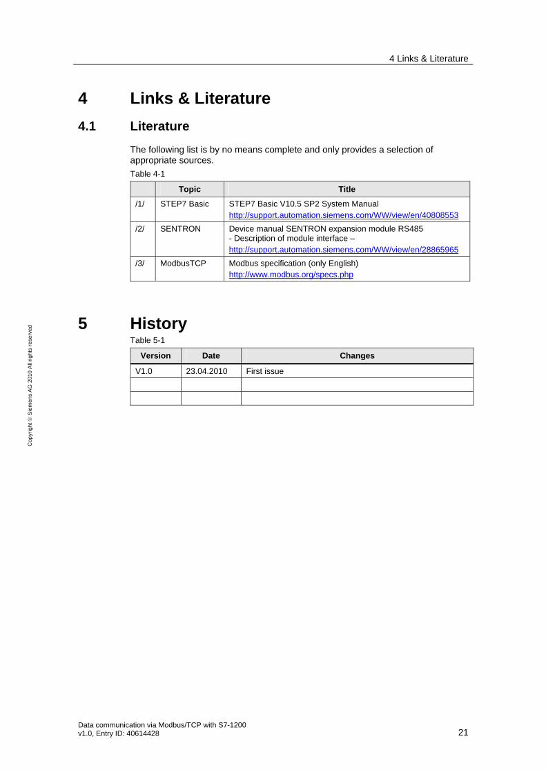
The following list is by no means complete and only provides a selection of appropriate sources.
Table 4-1
Topic Title
/1/ STEP7 Basic STEP7 Basic V10.5 SP2 System Manual http://support.automation.siemens.com/WW/view/en/40808553
/2/ SENTRON Device manual SENTRON expansion module RS485 - Description of module interface – http://support.automation.siemens.com/WW/view/en/28865965
/3/ ModbusTCP Modbus specification (only English) http://www.modbus.org/specs.php
5 History Table 5-1
Version Date Changes
V1.0 23.04.2010 First issue
![LAN DISK 管理マニュアル - I-O Data...で192.168.0.200と表示されている場合は、スタートをクリックし、[検索の開始]をクリック後、 「\\192.168.0.200」と入力し[Enter]キーを押します。](https://img.pdfslide.us/doc/110x75/5e87b142a733723e02513b7b/lan-disk-ccffff-i-o-1921680200ecoefffffoecefffoe.jpg)


![Sentron Pac3200 Manual en 04[1]](https://img.pdfslide.us/doc/110x75/553e86ef55034684398b4a4e/sentron-pac3200-manual-en-041.jpg)
