Embed Size (px)
Citation preview

MB
SM
A
RAMS 2020 - PAPER ID 71 Jan 29th 2020 Model-based System Engineering for Reliability Analysis SESSION – 12
Reliability Analysis of Complex NASA Systemswith Model Based Engineering
Nancy J. Lindsey, Risk & Reliability Branch Head NASA/GSFCMahdi Alimardani, Reliability Engineer NASA/GSFCLuis D. Gallo, Reliability Engineer NASA/GSFC
Sponsored by NASA/HQ : John Evans and Anthony DiVenti
https://ntrs.nasa.gov/search.jsp?R=20200000583 2020-04-13T09:58:50+00:00Z

N A S A M O D E L B A S E D S a f e t y a n d M i s s i o n A s s u r a n c e
2
MBSMA Initiative Pathfinder Partner Project Objectives
Is Model-Based Engineering valid and useable for Reliability Engineering for NASA mission Safety and Mission Assurance ?
• Investigate methodologies for the deployment of Model Based SMA/MA:
– Reliability (e.g., FMECA, LLA, FTA, PRA, Maintainability, Availability)– System Safety (e.g., MSPSP, Hazard Analysis)– Software Assurance (e.g., Control/Testing Plans, Process/Supplier Risks, Software FMECA/FTA)– Quality Assurance (e.g., Control/Testing Plans, Process/Supplier Risks, Parts/Materials Approvals,
Mission Assurance Requirements, PRACA/FRACAs)
• Provide Recommendations, Guidance, and Risk-Based Strategies for MBSMA/MA and MBSE Collaboration

N A S A M O D E L B A S E D S a f e t y a n d M i s s i o n A s s u r a n c e
MBSMAI Methodology
3
Use three mission test cases to evaluate the ability of Model-Based Engineering to support Reliability Analyses of Probability Analysis (PA)) Failure Mode Effects and Criticality Analysis (FMECA), Fault Tree Analysis (FTA), and Limited Life Analysis (LLA).

N A S A M O D E L B A S E D S a f e t y a n d M i s s i o n A s s u r a n c e
MBSMAI Methodology
4
Model
Report
Evaluate
Itera
teModel
Report
Evaluate
Itera
te
Model
Report
Evaluate
Itera
te
Itera
te
Model
Report
Evaluate
Itera
te
Model
Report
Evaluate
Itera
te
Model
Report
Evaluate
Modeling Process Guidance
Optimal Modeling Environment Requirements*
* Tool readiness was also assessed.
MAD
eSy
sML/
Mag
icD
raw
N A S A M O D E L B A S E D S a f e t y a n d M i s s i o n A s s u r a n c e
MBSMAI Phase 1: EUROPA Propulsion Modeling
Failure Diagrams and Functional Block Diagrams are the core of the MADe
model. 5

N A S A M O D E L B A S E D S a f e t y a n d M i s s i o n A s s u r a n c e
6
MBSMAI Phase 1: EUROPA Propulsion Modeling
Failure Diagrams and Functional Block Diagrams are the core of the MADe
model.

N A S A M O D E L B A S E D S a f e t y a n d M i s s i o n A s s u r a n c e
MBSMAI Phase 1: EUROPA Propulsion Modeling
The inherent error checking capability of MADe was able to alert the modeler of any discrepancy in the design.
7

N A S A M O D E L B A S E D S a f e t y a n d M i s s i o n A s s u r a n c e
MBSMAI Phase 1: EUROPA Propulsion Modeling
8
Defining the model required the modeler to use different elements i.e. Block, Operation, Signal, etc.) and different diagrams (i.e. State
Machine Diagram).
Defining the model required the modeler to use different elements i.e. Block, Operation, Signal, etc.) and different diagrams (i.e. State
Machine Diagram).

N A S A M O D E L B A S E D S a f e t y a n d M i s s i o n A s s u r a n c e
MBSMAI Phase 1: EUROPA Propulsion Modeling
Defining Orthogonal State Machines with appropriate Guard Conditions are required in order to define Redundancy in SysML/MagicDraw when using
Tietronox Plugin.
Appropriate signal were defined in order to connect the model at different levels.
9
N A S A M O D E L B A S E D S a f e t y a n d M i s s i o n A s s u r a n c e
MBSMAI Phase 1: EUROPA Propulsion Modeling
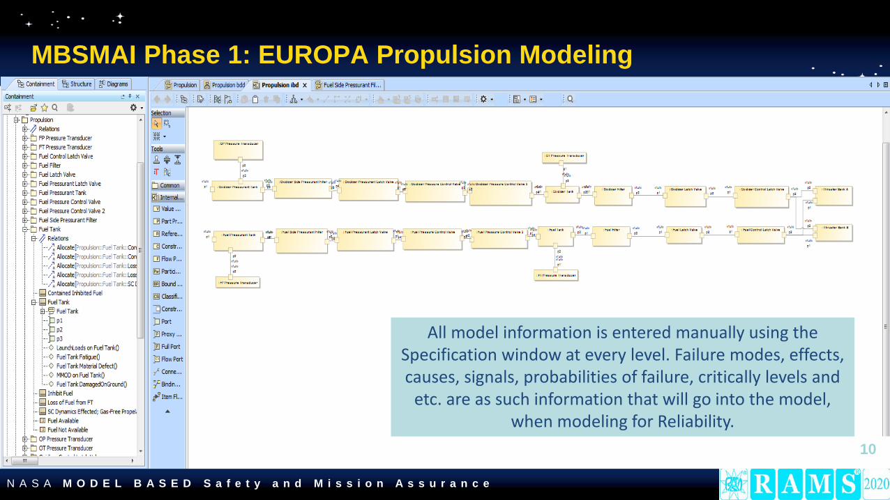
10
All model information is entered manually using the Specification window at every level. Failure modes, effects, causes, signals, probabilities of failure, critically levels and
etc. are as such information that will go into the model, when modeling for Reliability.
N A S A M O D E L B A S E D S a f e t y a n d M i s s i o n A s s u r a n c e
MBSMAI Phase 1: EUROPA Model Probability Analysis Evaluation
11
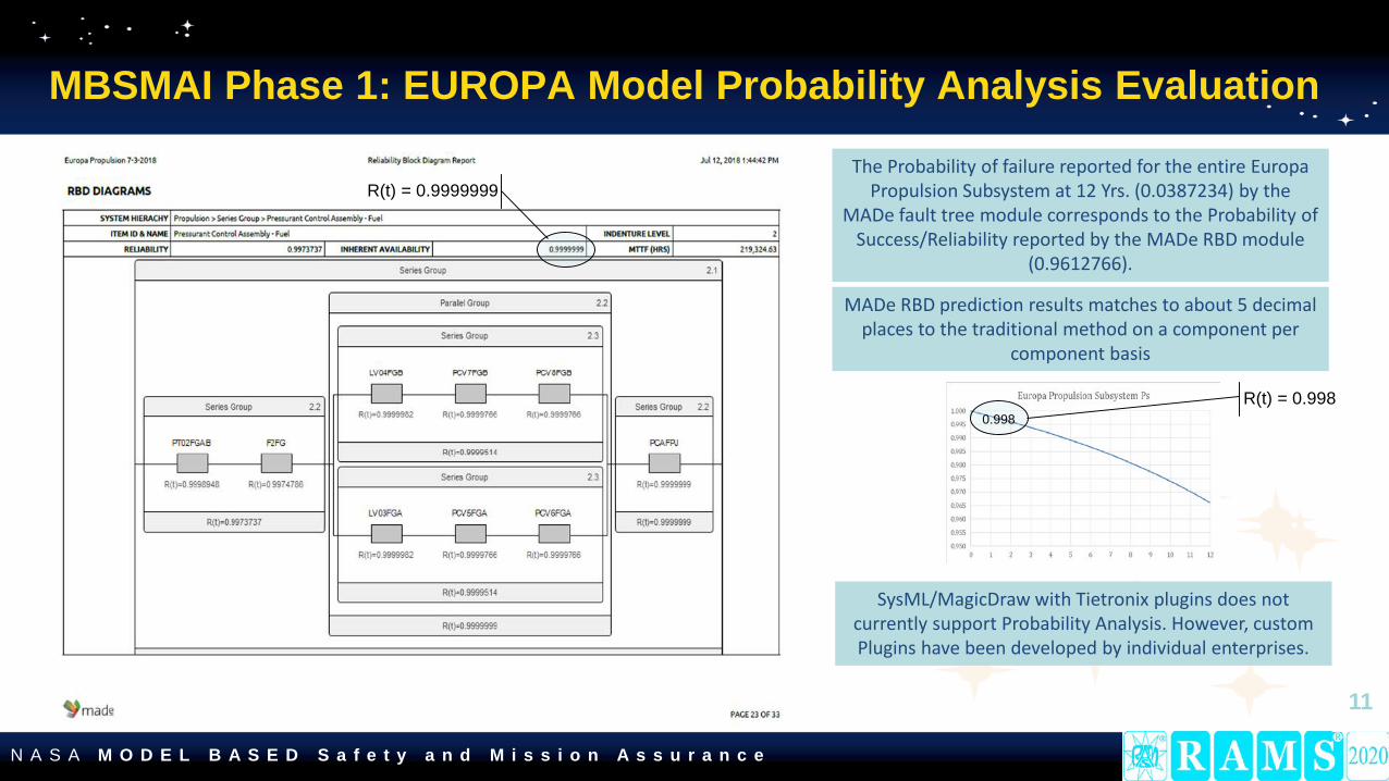
The Probability of failure reported for the entire Europa Propulsion Subsystem at 12 Yrs. (0.0387234) by the
MADe fault tree module corresponds to the Probability of Success/Reliability reported by the MADe RBD module
(0.9612766).
0.998
MADe RBD prediction results matches to about 5 decimal places to the traditional method on a component per
component basis
SysML/MagicDraw with Tietronix plugins does not currently support Probability Analysis. However, custom Plugins have been developed by individual enterprises.
R(t) = 0.9999999
R(t) = 0.998
N A S A M O D E L B A S E D S a f e t y a n d M i s s i o n A s s u r a n c e
MBSMAI Phase 1: EUROPA Model Fault Tree Evaluation
12
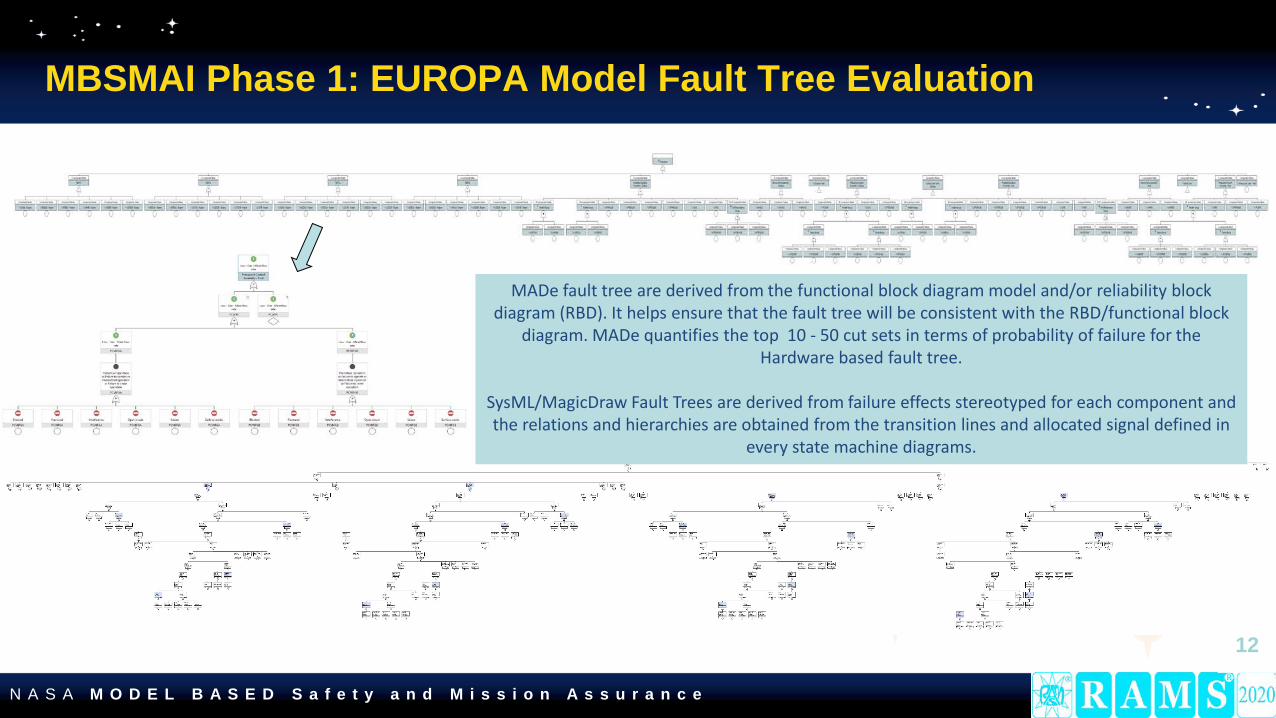
MADe fault tree are derived from the functional block diagram model and/or reliability block diagram (RBD). It helps ensure that the fault tree will be consistent with the RBD/functional block
diagram. MADe quantifies the top 10 - 50 cut sets in terms of probability of failure for the Hardware based fault tree.
SysML/MagicDraw Fault Trees are derived from failure effects stereotyped for each component and the relations and hierarchies are obtained from the transition lines and allocated signal defined in
every state machine diagrams.
N A S A M O D E L B A S E D S a f e t y a n d M i s s i o n A s s u r a n c e
MBSMAI Phase 1: EUROPA Model Failure Modes Effects and Criticality Analysis (FMECA)
13
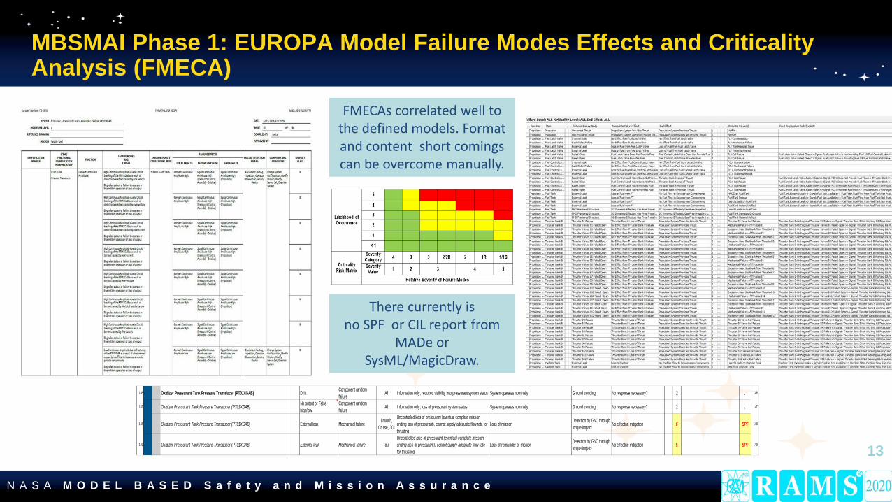
146 Oxidizer Pressurant Tank Pressure Transducer (PT01XGAB) Drift Component random failure All Information only, reduced visibility into pressurant system status System operates nominally Ground trending No response necessary? 2 . 146
147 Oxidizer Pressurant Tank Pressure Transducer (PT01XGAB) No output or False high/low
Component random failure All Information only, loss of pressurant system status System operates nominally Ground trending No response necessary? 2 . 147
148 Oxidizer Pressurant Tank Pressure Transducer (PT01XGAB) External leak Mechanical failure Launch, Cruise, JOI
Uncontrolled loss of pressurant (eventual complete mission ending loss of pressurant), cannot supply adequate flow rate for thrusting
Loss of mission Detection by GNC through torque impact No effective mitigation 6 SPF 148
149 Oxidizer Pressurant Tank Pressure Transducer (PT01XGAB) External leak Mechanical failure TourUncontrolled loss of pressurant (eventual complete mission ending loss of pressurant), cannot supply adequate flow rate for thrusting
Loss of remainder of mission Detection by GNC through torque impact No effective mitigation 5 SPF 149
There currently is no SPF or CIL report from
MADe or SysML/MagicDraw.
FMECAs correlated well to the defined models. Format and content short comings can be overcome manually.

N A S A M O D E L B A S E D S a f e t y a n d M i s s i o n A s s u r a n c e
MBSMAI Phase 1: Sounding Rocket Modeling
14
N A S A M O D E L B A S E D S a f e t y a n d M i s s i o n A s s u r a n c e
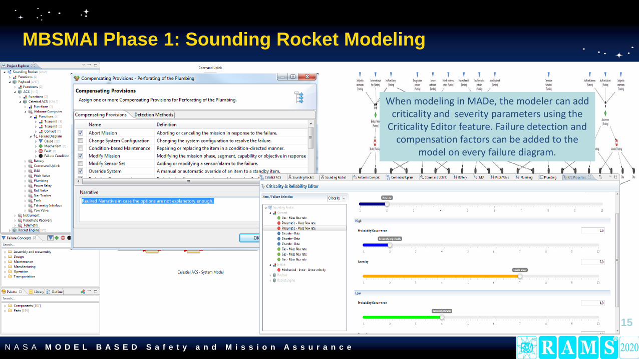
MBSMAI Phase 1: Sounding Rocket Modeling
15
When modeling in MADe, the modeler can add criticality and severity parameters using the
Criticality Editor feature. Failure detection and compensation factors can be added to the
model on every failure diagram.

N A S A M O D E L B A S E D S a f e t y a n d M i s s i o n A s s u r a n c e
MBSMAI Phase 1: Sounding Rocket Modeling
16
State Machines are the core of the model when modeling in
SysML/MagicDraw for Tietronix and we need a state machine at every level.
All model information was entered manually using the Specification
window at every level. Failure modes, effects, causes, signals, probabilities of failure, critically
levels and etc. are as such information that will go into the
model, when modeling for Reliability.

N A S A M O D E L B A S E D S a f e t y a n d M i s s i o n A s s u r a n c e
MBSMAI Phase 1: Sounding Rocket Probability Analysis Evaluation
17
The Probability of failure reported for the Sounding Rocket MADe model corresponds to the Probability of Success/Reliability of the traditional method at the component
level; mission life probabilities also compare favorably if the duration and duty cycles
assumed for each are the same.
SysML/MagicDraw with Tietronix plugins does not currently support Probability Analysis. However,
custom Plugins have been developed by individual enterprises.
R(t) = 0.9999965
R(t) = 0.999998923

N A S A M O D E L B A S E D S a f e t y a n d M i s s i o n A s s u r a n c e
MBSMAI Phase 1: Sounding Rocket Fault Tree Evaluation
SysML/MagicDraw FT output from the TietronixPlugin shows immediate
Failure Causes as the basic event not hardware failure since State Diagrams were optimized for the FMECA.
MADe, and Traditional
Method Fault Trees show similar basic
events.
18
SysML/MagicDraw Fault Trees also contain Boolean logic
errors (i.e., events decomposed into to subordinate events
without a combining logic or gate, and logic gates with only
one input) but perform accurate Boolean math.

N A S A M O D E L B A S E D S a f e t y a n d M i s s i o n A s s u r a n c e
MBSMAI Phase 1: Sounding Rocket Model Failure Modes Effects and Criticality Analysis (FMECA) Evaluation
SysML/MagicDraw Severity and Likelihood values are entered manually and can correlate to the
GSFC Risk definitions. To have a complete FMECA all thinking and data entry for to calculate RPN
would be done at manually at the modeling stage and the plugin will extract the data and tabulate it
for the user. 19
Narrative additions were used to clarify MADe FMECA outputs but
tool modifications may be required to synthesize/input mission consequences more
autonomously.

N A S A M O D E L B A S E D S a f e t y a n d M i s s i o n A s s u r a n c e
MBSMAI Phase 1: HUMAN SYSTEM – CapiBRIC Modeling
20
The CapiBRICSysML model in
SysML/MagicDrawprovided by JSC consisted of a
Block Definition Diagram, a wiring Diagram and 13 state machines
In MADe a limited model was developed
that consisted of 1 main
functional block diagram and 1
failure diagram.

N A S A M O D E L B A S E D S a f e t y a n d M i s s i o n A s s u r a n c e
MBSMAI Phase 1: CapiBRIC Model Fault Tree Evaluation
Traditional fault tree method was used to confirm that the hardware fault tree quantification in MADe was equivalent to
those in traditional software tool.
The SysML/MagicDraw CapiBRIC model was provided to the MBSMAI model development and evaluation team and not developed internally
so the model structure is similar but not exactly the same as that in MADe or traditional analysis performed by the team
21

N A S A M O D E L B A S E D S a f e t y a n d M i s s i o n A s s u r a n c e
MBSMAI Phase 1: CapiBRIC Model Failure Modes Effects and Criticality Analysis (FMECA) Evaluation
22
It is currently unclear if a SysML model FMECA can be customized to characterize severity/likelihood for risk assessment. SysML/MagicDrawFMECAs were generated at the system, and all other lower levels using
Tietronix FMEA Plugin. MagicDraw Tietronix generated FMECAs were found to correspond well with traditional artifacts in content and format when the
state machines were defined accordingly.
MADe FMECAs were generated at the system, and fully decomposed levels using a simple override/mode setting. MADe FMECAs were found
to relatively correspond well with traditional artifacts in content and format once optional mission specific narratives were added.
N A S A M O D E L B A S E D S a f e t y a n d M i s s i o n A s s u r a n c e
Model-Based Engineering is found to be valid and useable for Reliability Engineering for NASA Safety and Mission Assurance,
if adequate modeling processes and environment are established.
23
IS MODEL-BASED ENGINEERING VALID AND USEABLE FOR RELIABILITY ENGINEERING?

N A S A M O D E L B A S E D S a f e t y a n d M i s s i o n A s s u r a n c e
Recommended Process Guidance for Cross-Discipline Model-Based Engineering
24
Pre- Requisite: Establish Modelling process and controls
1) Establish a multi-discipline modeling team (Systems Engineering (SE) and SMA at a minimum);
2) Establish modeling responsibilities (e.g., SE’s model requirements, Designer’s model structure (Functional Block Diagram/Wire Diagram), REs model failure behaviors and characteristics) and controls;
3) Complete modeling and share common data between modelling elements; 4) Produce Reliability artifacts and share resulting data between modelling elements; 5) Verify and refine modelling (and designs) until a final and acceptable result is
achieved; 6) Share modeling with future missions.

N A S A M O D E L B A S E D S a f e t y a n d M i s s i o n A s s u r a n c e
Recommended Optimal Modeling Environment Requirementsfor Cross-Discipline Model-Based Engineering
25
The Modeling environment/tool shall:
• Be easily mastered structure and interface for efficiency.• Support for the development of models from the traditional reliability artifacts rather than only deriving the artifacts
from the models for efficiency via model re-use.• Have the ability to create a functional model of the systems for efficiency and clarity.• Have the ability to ensure that changes to one diagram (e.g., adding a component) propagates to other parts/diagrams
of the model automatically or at least shows as an error that needs to be resolved by the modeler.• Have the ability to allocate requirements to a functional diagram/element for consistent and accurate effect
assessment.• Include modeling diagrams that connect hierarchically to each other for efficiency and clarity which will allow non-
modelers to easily traverse and drill down within the model for understanding and accuracy validation.• Have Libraries of standard components with baseline failure and function data for consistency and accuracy.• Have Libraries of standard failure mechanisms and causes for consistency and efficiency.• Have the ability to combine models and duplicate modeling for efficiency.• Include Model component and system error checking for accuracy. • Include Model change control/reporting for accuracy.• Have performance that shortens analysis time while maintaining consistency and accuracy between models.• Have the ability to add models of systems or portions of systems to a library of shareable models for efficiency.

N A S A M O D E L B A S E D S a f e t y a n d M i s s i o n A s s u r a n c e
Recommended Optimal Modeling Environment Requirementsfor Cross-Discipline Model-Based Engineering
26
The Modeling environment/tool shall:
• Have the ability to produce a FMECA with NASA defined levels and characterization factors, a Fault tree with precise Boolean logic for accuracy, life assessments at the component and system level, and availability assessments at the component and system level.
• Have the ability to perform maintainability assessments interconnected with maintenance/sparing plans at the component and system level.
• Have the ability to import requirements, CAD and BOM/part lists type data to create modeling elements or as supporting data for efficiency.
• Have the ability to select requirements allocated to each element as the effects and functions for accuracy and efficiency.
• Include an export function to other modeling formats and reliability tools (e.g., Windchill Prediction tool (formerly Relex), Saphire, QRAS, etc.)
• Have the ability to perform probability analysis using at least 217F, Telecordia, FIDES, PRISM, and/or enterprise custom databases (SEAM). Or import data from reliability tools (e.g., Windchill Prediction tool, etc.) for accuracy and efficiency.
• Have the ability to import results (e.g., radiation effects, life expectancy data, traditional analysis data) from other models or sources for efficiency and accuracy.

N A S A M O D E L B A S E D S a f e t y a n d M i s s i o n A s s u r a n c e
Conclusion and Path Forward
Conclusions
• Model-Based Organizations, including NASA, must decide for themselves how to implement model-based engineering in a way that makes sense for all their engineering, assurance, operational, and production elements. Therefor it is essential to the subject matter experts from each element as early as possible.
• Not all tools are ready to support all disciplines.
Path Forward
• Conduct Phase 2 of this study in which evaluations and testing will consist of follow-on Reliability evaluations with more complex system/model (e.g., Cubesat Mission) and Safety Analyses.
• Work with tool vendor’s to customize tools for even more compatibility with SMA disciplines.
• Conduct Phase 3 of this study which will evaluate Software Assurance and Quality Engineering Analysis compatibility.
20

N A S A M O D E L B A S E D S a f e t y a n d M i s s i o n A s s u r a n c e
21