Embed Size (px)
Citation preview

E22” Elima-Matic Bolted Non-Metallicwith Metallic Center Section
Performance
Dimensions
Specifications
NOTE: Performance based on the following: elastomeric fitted pump, flooded suction, water at ambient conditions. The use of other materials and varying hydraulic conditions may result in deviations in excess of 5%.
Disc
harg
e Hea
d in
PSI
0Capacity in Liters Per Minute
Capacity in U.S. Gallons Per Minute
Displacement Per Stroke, 0.52 Gal. (2.0 L)
AIR CONSUMPTION IN SCFMAIR PRESSURE IN PSI
SCFM M3/HR 10 17 20 34 40 51 60 102 80 136 100 170 120 204
00
20
40
60
80
100
20
80 160 240 320 400 480 560 640 720
10 20 4060
80
100
120
40 60 80 100 120 140 160 180Meters Feet
240
220
200
180
160
140
120
100
80
60
40
20
0
75 70 65 60 55 50 45 40 35 30 25 20 15 10 5 0 0
1
3
2
4
5
6
7
BAR
Flow RateAdjustable to . . . . . . . 0-177 gpm (670 lpm)
Port Size Suction . . . . . . .2" ANSI, 150 Class (DIN 50) Discharge . . . . .2" ANSI, 150 Class (DIN 50)Air Inlet . . . . . . . . . . . . . . . . . . . . . . 1/2" NPTAir Exhaust . . . . . . . . . . . . . . . . . . . 1" NPTSuction Lift Dry . . . . . . . . . . . . . . . . . . . . . . . .16' (4 .9 m) Wet . . . . . . . . . . . . . . . . . . . . . . . .32' (9 .8 m)Max Solid Size (Diameter)
. . . . . . . . . . . . . . . . . . . . . . . . 1/4" (6 .3 mm)Max Noise Level . . . . . . . . . . . . . 96 dB(A)Shipping Weights Polypropylene . . . . . . . . . . .69 lbs (31 .3 kg)
w/ center port options . . . . . .73 lbs (33 .1 kg) PVDF . . . . . . . . . . . . . . . . . .93 lbs (42 .2 kg)
w/ center port options . . . . .100 lbs (45 .4 kg)
NOTES:
8
A
.84
11.55
21.58
30.25
19.82
1/2" NPTAIR INLET
1" NPTAIR EXHAUST
R.28
10.00
12.81
9.00
15.07
2.26
3.02
27.25
12.01
2" 150# ANSI / DINDISCHARGE FLANGE
2" 150# ANSI / DINSUCTION FLANGE
BOTTOM VIEW
NOTES:
8
A
.84
11.55
21.58
30.25
19.82
1/2" NPTAIR INLET
1" NPTAIR EXHAUST
R.28
10.00
12.81
9.00
15.07
2.26
3.02
27.25
12.01
2" 150# ANSI / DINDISCHARGE FLANGE
2" 150# ANSI / DINSUCTION FLANGE
BOTTOM VIEW
NOTES:
8
A
.84
11.55
21.58
30.25
19.82
1/2" NPTAIR INLET
1" NPTAIR EXHAUST
R.28
10.00
12.81
9.00
15.07
2.26
3.02
27.25
12.01
2" 150# ANSI / DINDISCHARGE FLANGE
2" 150# ANSI / DINSUCTION FLANGE
BOTTOM VIEW
JH Process Equipment Inc. | 617 Jeffers Circle, Exton, PA 19341 | 610-903-0900 | www.jhprocess.com

Ver
sa-M
atic
E2 Non-Metallic Pumps• Polypropylene• PVDF
2" Elima-Matic Bolted Non-Metallicwith Metallic Center Section E2
Serv
ice
& O
per
ati
ng
Ma
nu
al
1: P
UMP
SPEC
S2:
INST
AL &
OP
3: E
XP V
IEW
4: W
ARRA
NTY
Orig
inal
Inst
ruct
ions
JH Process Equipment Inc. | 617 Jeffers Circle, Exton, PA 19341 | 610-903-0900 | www.jhprocess.com

IMPORTANT
Read the safety warnings and instructions in this manual before pump installation and start-up. Failure to comply with the recommendations stated in this manual could damage the pump and void factory warranty.
When used for toxic or aggressive fluids, the pump should always be flushed clean prior to disassembly.
Airborne particles and loud noise hazards. Wear eye and ear protection.
Before maintenance or repair, shut off the compressed air line, bleed the pressure, and disconnect the air line from the pump. Be certain that approved eye protection and protective clothing are worn at all times. Failure to follow these recommendations may result in serious injury or death.
To be fully groundable, the pumps must be ATEX Compliant. Refer to the nomenclature page for ordering information.
Optional 8 foot long (244 centimeters) Ground Strap is available for easy ground connection.
To reduce the risk of static electrical sparking, this pump must be grounded. Check the local electrical code for detailed grounding instruction and the type of equipment required.
Refer to nomenclature page for ordering information.
When the pump is used for materials that tend to settle out or solidify, the pump should be flushed after each use to prevent damage. In freezing temperatures the pump should be completely drained between uses.
Before pump operation, inspect all fasteners for loosening caused by gasket creep. Retighten loose fasteners to prevent leakage. Follow recommended torques stated in this manual.
CAUTION
WARNING
Nonmetallic pumps and plastic components are not UV stabilized. Ultraviolet radiation can damage these parts and negatively affect material properties. Do not expose to UV light for extended periods of time.
In the event of diaphragm rupture, pumped material may enter the air end of the pump, and be discharged into the atmosphere. If pumping a product that is hazardous or toxic, the air exhaust must be piped to an appropriate area for safe containment.
This pump is pressurized internally with air pressure during operation. Make certain that all fasteners are in good condition and are reinstalled properly during reassembly.
Take action to prevent static sparking. Fire or explosion can result, especially when handling flammable liquids. The pump, piping, valves, containers and other miscellaneous equipment must be properly grounded.
Safety Information
Grounding the Pump
WARNINGTake action to prevent static sparking. Fire or explosion can result, especially when handling flammable liquids. The pump, piping, valves, containers or other miscellaneous equipment must be grounded.
WARNINGPump not designed, tested or certified to be powered by compressed natural gas. Powering the pump with natural gas will void the warranty.
Use safe practices when liftingkg
UNIVERSAL ALL AODD
JH Process Equipment Inc. | 617 Jeffers Circle, Exton, PA 19341 | 610-903-0900 | www.jhprocess.com

Table of Contents
SECTION 1: PumP SPECIfICaTIONS ................1• Nomenclature• Performance• Materials• DimensionalDrawings
SECTION 2: INSTallaTION & OPEraTION ......6• PrincipleofPumpOperation• TypicalInstallationGuide• Troubleshooting
SECTION 3: ExPlOdEd VIEw ...........................9• CompositeDrawings• PartsList• MaterialsCode
SECTION 4: warraNTy & CErTIfICaTES ....13• Warranty• CEDeclarationofConformity-Machinery
Universal*
1: P
UMP
SPEC
S2:
INST
AL &
OP
3: E
XP V
IEW
4: W
ARRA
NTY
JH Process Equipment Inc. | 617 Jeffers Circle, Exton, PA 19341 | 610-903-0900 | www.jhprocess.com

1 • Model E2 Non-Metallic Bolted
Explanation of Pump Nomenclature
*More than one option may be specified for a particular pump model.
Model Pump Size Wetted Parts Non-Wetted Parts Diaphragm MaterialE Elima-Matic 6 1/4" A Aluminum A Aluminum 1 NeopreneUUltra-Matic 8 3/8" C Cast Iron S Stainless Steel 2Nitrile(Nitrile)VV-Series 5 1/2" S Stainless Steel PPolypropylene 3 FKM(Fluorocarbon)RE AirVantage 7 3/4" H Alloy C G Groundable Acetal 4EPDM
1 1" PPolypropylene ZPTFE-coatedAluminum 5PTFE41-1/4"or1-1/2" K Kynar JNickel-platedAluminum 6SantopreneXL2 2" G Groundable Acetal C Cast Iron 7 Hytrel3 3" B Aluminum (screen mount) QEpoxy-CoatedAluminum 9 Geolast
YFDASantoprene
Diaphragm Series Valve Ball Material Valve Seat/Valve Seat O-Ring Material Construction Design Miscellaneous OptionsR Rugged 1Neoprene 1 Neoprene 9 Bolted BBSPTaperedThreadDDome 2 Nitrile 2Nitrile 0 Clamped CPCenterPortXThermo-Matic 3(FKM)Fluorocarbon 3(FKM)Fluorocarbon ATEXATEXCompliantTTef-Matic(2-piece) 4EPDM 4EPDM Design Level FPFoodProcessingBVersa-Tuff(1-piece) 5PTFE 5PTFE A SPSanitaryPumpFFUSION(one-piece 6SantopreneXL 6SantopreneXL C HPHighPressureintegrated plate) 7 Hytrel 7 Hytrel OEOriginalElima-Matic
8 Polyurethane 8Polyurethane F Flap Valve9 Geolast 9 Geolast HDHorizontalDischargeA Acetal AAluminumw/PTFEO-Rings 3A3-ACertifiedS Stainless Steel SStainlessSteelw/PTFEO-Rings ULULListedYFDASantoprene CCarbonSteelw/PTFEO-Rings OB Oil Bottle
HAlloyCw/PTFEO-RingsTPTFEEncapsulatedSiliconeO-RingsYFDASantoprene
Model
Pump Size
Wetted Parts
Non-Wetted Parts
Diaphragm Material
Diaphragm Series
Valve Ball Material
Valve Seat Material/Valve Seat O-Ring Material
Construction Design
Design Level
Options (if applicable)
Your Serial #: (fill in from pump nameplate) _____________________________________
Model #:
__ __ __ __ __ __ __ __ __ __ __ __ __(fill in from pump nameplate)
Your Model #:
UNIVERSAL TO ALL VM
1: P
UMP
SPEC
S
JH Process Equipment Inc. | 617 Jeffers Circle, Exton, PA 19341 | 610-903-0900 | www.jhprocess.com

Model E2 Non-Metallic Bolted • 2
materials
Material Profile: Operating Temperatures:Max. Min.
Conductive Acetal: Tough, impact resistant, ductile. Good abrasionresistanceandlowfrictionsurface.Generallyinert,withgoodchemicalresistanceexceptforstrongacidsandoxidizingagents.
190°F88°C
-20°F-29°C
EPDM:Showsverygoodwaterandchemicalresistance.Haspoor resistance to oils and solvents, but is fair in ketones and alcohols.
280°F138°C
-40°F-40°C
FKM:(Fluorocarbon)Showsgoodresistancetoawiderange of oils and sovents; especially all aliphatic, aromatic and halogenated hydrocarbons, acids, animal and vegetable oils. Hotwaterorhotaqueoussolutions(over70°F)willattackFKM.
350°F177°C
-40°F-40°C
Hytrel®: Good on acids, bases, amines and glycols at room temperatures only.
220°F104°C
-20°F-29°C
Neoprene: All purpose. Resistance to vegetable oils. Generally not affected by moderate chemicals, fats, greases and many oilsandsolvents.Generallyattackedbystrongoxidizingacids,ketones, esters and nitro hydrocarbons and chlorinated aromatic hydrocarbons.
200°F93°C
-10°F-23°C
Nitrile: Generalpurpose,oil-resistant.Showsgoodsolvent,oil,waterandhydraulicfluidresistance.ShouldnotbeusedwithhighlypolarsolventslikeacetoneandMEK,ozone,chlorinatedhydrocarbons and nitro hydrocarbons.
190°F88°C
-10°F-23°C
Nylon: 6/6Highstrengthandtoughnessoverawide temperaturerange.Moderatetogoodresistancetofuels,oilsand chemicals.
180°F82°C
32°F0°C
Polypropylene:Athermoplasticpolymer.Moderatetensileandflexstrength.Resistsstongacidsandalkali.Attackedbychlorine,fumingnitricacidandotherstrongoxidizingagents.
180°F82°C
32°F0°C
PVDF:(PolyvinylideneFluoride)Adurablefluoroplasticwithexcellentchemicalresistance.ExcellentforUVapplications.High tensile strength and impact resistance.
250°F121°C
0°F-18°C
Santoprene®:Injectionmoldedthermoplasticelastomerwithnofabriclayer.Longmechanicalflexlife.Excellentabrasionresistance.
275°F135°C
-40°F-40°C
UHMW PE: A thermoplastic that is highly resistant to a broad rangeofchemicals.Exhibitsoutstandingabrasionandimpactresistance,alongwithenvironmentalstress-crackingresistance.
180°F82°C
-35°F-37°C
Urethane:Showsgoodresistancetoabrasives.Haspoorresistance to most solvents and oils.
150°F66°C
32°F0°C
Virgin PTFE:(PFA/TFE)Chemicallyinert,virtuallyimpervious.VeryfewchemicalsareknowntochemicallyreactwithPTFE;moltenalkalimetals,turbulentliquidorgaseousfluorineandafewfluoro-chemicalssuchaschlorinetrifluorideoroxygendifluoridewhichreadilyliberatefreefluorineatelevated temperatures.
220°F104°C
-35°F-37°C
Maximum and Minimum Temperatures are the limits for which these materials can be operated. Temperatures coupled with pressure affect the longevity of diaphragm pump components. Maximum life should not be expected at the extreme limits of the temperature ranges.
Metals:Alloy C:EqualtoASTM494CW-12M-1specificationfornickelandnickelalloy.Stainless Steel: EqualtoorexceedingASTMspecificationA743CF-8Mforcorrosionresistant iron chromium, iron chromium nickel and nickel based alloy castings for general applicaitons. Commonly referred to as 316 Stainless Steel in the pump industry.
For specific applications, always consult the Chemical Resistance Chart.
CAUTION! Operating temperature limitations are as follows:
afTErmarKET ParTS
Pumper Parts is your single source for parts that fit Air-Operated Double Diaphragm (AODD) pumps
• Wilden®
• ARO®
• Yamada®
RIGHT PART, RIGHT NOW
designed to perform equal to or greater than original equipment manufacture.
Phone: (419) 526-7296info@pum perparts.comwww.pumperparts.com
Pumper Parts and its products are not affiliated with any of the original equipment manufacturers referenced herein. All original equipment manufacturers’ names, colors, pictures, descriptions and part numbers are used for identification purposes only. Pumper Parts® is a registered trade name of IDEX Corporation. All other trademarks, registered trademarks and product names are the property of their respective owners. Yamada® is a registered trademark of Yamada Corporation. ARO® is a registered trade name of Ingersoll-Rand Company. Wilden® is a registered trade name of Wilden Pump and Engineering Company, a Dover Resources Company.
MODEL SPECIFIC UNIVERSAL ALL AODD
1: P
UMP
SPEC
S
JH Process Equipment Inc. | 617 Jeffers Circle, Exton, PA 19341 | 610-903-0900 | www.jhprocess.com

3 • Model E2 Non-Metallic Bolted
PerformanceE2 - 2” Non-Metallic Bolted Pump – Metallic CenterELASTOMERIC AND TPE FITTED - Domed
Flow Rate Adjustable to . . . . . . . 0-177gpm(670lpm)Port Size Suction . . . . . . .2"ANSI,150Class(DIN50) Discharge . . . . .2"ANSI,150Class(DIN50)Air Inlet . . . . . . . . . . . . . . . . . . . . . . 1/2"NPTAir Exhaust . . . . . . . . . . . . . . . . . . . 1"NPTSuction Lift
Dry . . . . . . . . . . . . . . . . . . . . . . . .16' (4.9 m) Wet. . . . . . . . . . . . . . . . . . . . . . . .32' (9.8 m)Max Solid Size(Diameter) . . . . . . . . . . . . . . . . . . . . . . . . 1/4" (6.3 mm)Max Noise Level . . . . . . . . . . . . . 96 dB(A)Shipping Weights
Polypropylene . . . . . . . . . . .69 lbs (31.3 kg)w/centerportoptions. . . . . .73lbs(33.1kg)PVDF . . . . . . . . . . . . . . . . . .93 lbs (42.2 kg) w/centerportoptions. . . . .100 lbs (45.4 kg)
E2 - 2” Non-Metallic Bolted Pump – Metallic CenterPTFE FITTED
Flow Rate Adjustable to . . . . . . . 0-145gpm(549lpm)Port Size Suction . . . . . . .2"ANSI,150Class(DIN50) Discharge . . . . .2"ANSI,150Class(DIN50)Air Inlet . . . . . . . . . . . . . . . . . . . . . . 1/2"NPTAir Exhaust . . . . . . . . . . . . . . . . . . . 1"NPTSuction Lift
Dry . . . . . . . . . . . . . . . . . . . . . . . . .8' (2.4 m) Wet. . . . . . . . . . . . . . . . . . . . . . . .30' (9.1 m)Max Solid Size(Diameter) . . . . . . . . . . . . . . . . . . . . . . . . 1/4" (6.3 mm)Max Noise Level . . . . . . . . . . . . . 99 dB(A)Shipping Weights
Polypropylene . . . . . . . . . . .69 lbs (31.3 kg)w/centerportoptions. . . . . .73lbs(33.1kg)PVDF . . . . . . . . . . . . . . . . . .93 lbs (42.2 kg) w/centerportoptions. . . . .100 lbs (45.4 kg)
Disc
harg
e Hea
d in
PSI
0Capacity in Liters Per Minute
Capacity in U.S. Gallons Per Minute
Capacity Per Stroke, 0.34 Gal. (1.3 L)
AIR CONSUMPTION IN SCFMAIR PRESSURE IN PSI
SCFM M3/HR 10 17 20 34 40 51 60 102 80 136 100 170 120 204
00
20
40
60
80
100
20
80 160 240 320 400 480 560
Meters Feet0 0
40
80
120
160
200
10
20
30
40
50
60
7010 20 40
6080
100
120
40 60 80 100 120 1400
1
3
2
4
5
6
7
BAR
NOTE: Performance based on the following: elastomeric fitted pump, flooded suction, water at ambient conditions. The use of other materials and varying hydraulic conditions may result in deviations in excess of 5%.
Disc
harg
e Hea
d in
PSI
0Capacity in Liters Per Minute
Capacity in U.S. Gallons Per Minute
Displacement Per Stroke, 0.52 Gal. (2.0 L)
AIR CONSUMPTION IN SCFMAIR PRESSURE IN PSI
SCFM M3/HR 10 17 20 34 40 51 60 102 80 136 100 170 120 204
00
20
40
60
80
100
20
80 160 240 320 400 480 560 640 720
10 20 4060
80
100
120
40 60 80 100 120 140 160 180Meters Feet
240
220
200
180
160
140
120
100
80
60
40
20
0
75 70 65 60 55 50 45 40 35 30 25 20 15 10 5 0 0
1
3
2
4
5
6
7
BAR
NOTE: Performance based on the following: elastomeric fitted pump, flooded suction, water at ambient conditions. The use of other materials and varying hydraulic conditions may result in deviations in excess of 5%.
1: P
UMP
SPEC
S
JH Process Equipment Inc. | 617 Jeffers Circle, Exton, PA 19341 | 610-903-0900 | www.jhprocess.com

Model E2 Non-Metallic Bolted • 4
E2 Non-Metallic Bolted Dimensionsininches(mm dimensions in brackets) The dimensions on this drawing are for reference only. A certified drawing can be requested if physical dimensions are needed.
dimensional drawings
NOTES:
8
A
.84
11.55
21.58
30.25
19.82
1/2" NPTAIR INLET
1" NPTAIR EXHAUST
R.28
10.00
12.81
9.00
15.07
2.26
3.02
27.25
12.01
2" 150# ANSI / DINDISCHARGE FLANGE
2" 150# ANSI / DINSUCTION FLANGE
BOTTOM VIEW
NOTES:
8
A
.84
11.55
21.58
30.25
19.82
1/2" NPTAIR INLET
1" NPTAIR EXHAUST
R.28
10.00
12.81
9.00
15.07
2.26
3.02
27.25
12.01
2" 150# ANSI / DINDISCHARGE FLANGE
2" 150# ANSI / DINSUCTION FLANGE
BOTTOM VIEW
NOTES:
8
A
.84
11.55
21.58
30.25
19.82
1/2" NPTAIR INLET
1" NPTAIR EXHAUST
R.28
10.00
12.81
9.00
15.07
2.26
3.02
27.25
12.01
2" 150# ANSI / DINDISCHARGE FLANGE
2" 150# ANSI / DINSUCTION FLANGE
BOTTOM VIEW
Model Specific
1: P
UMP
SPEC
S
JH Process Equipment Inc. | 617 Jeffers Circle, Exton, PA 19341 | 610-903-0900 | www.jhprocess.com

5 • Model E2 Non-Metallic Bolted
3.0276.58
11.55293.24
27.25692.15
21.58548.11
1.0025.40
2" 150 # ANSI / DINSUCTION FLANGE
2" 150 # ANSI / DINDISCHARGE FLANGE
1/2" NPTAIR INLET
1" NPTAIR EXHAUST
30.25768.35
4.14105.16
12.01305.15
R.287.11
10.00254.00
12.81325.45
9.00228.60
15.07382.85
2.2657.40
17.52445.03
NOTES:
1. THE DIMENSIONS ON THIS DRAWING ARE FOR REFERENCE ONLY. A CERTIFIED DRAWING CAN BE REQUESTED IF PHYSICAL DIMENSIONS ARE NEEDED.
BOTTOM VIEW
1 UPDATED TO CURRENT DESIGN MAV 3309
REV REVISION CHG DATE ECN
THIS IS A PROPRIETARY DOCUMENT. DO NOT REPRODUCE OR DISCLOSE WITHOUT THE EXPRESS WRITTEN PERMISSION OF WARREN RUPP INC.
MADE FROM
WETTED END MATERIAL:
PART NUMBER
DESCRIPTION
DRAWING NUMBER
WARREN RUPP INC.
REV
1
DO NOT SCALE DRAWING
DIMENSIONS ARE INCHES
SHEET
C
678
A
8 7 6 5 4 3 2 1
D
B
D
C
B
A
E2PAxxxx9C-CP
E2 CENTER PORTED PLASTIC BOLTED PUMP
1 1of
E2PAxxxx9C-CP
POLYPROYLENE / PVDF
SEE BOM
ALL DIAPHRAGM TYPES ELASTOMERIC MATERIAL:
AIR END MATERIAL:ALUMINUM
E2 Non-Metallic Bolted - Optional Center Porting Dimensionsininches(mm dimensions in brackets) The dimensions on this drawing are for reference only. A certified drawing can be requested if physical dimensions are needed.
dimensional drawings1:
PUM
P SP
ECS
JH Process Equipment Inc. | 617 Jeffers Circle, Exton, PA 19341 | 610-903-0900 | www.jhprocess.com

Model E2 Non-Metallic Bolted • 6
Air-OperatedDoubleDiaphragm(AODD)pumpsarepoweredby compressed air or nitrogen.
The main directional (air) control valve ① distributes compressedairtoanairchamber,exertinguniformpressureover the inner surface of the diaphragm ②. At the same time, theexhaustingair③ from behind the opposite diaphragm isdirectedthroughtheairvalveassembly(s)toanexhaust port ④.
As inner chamber pressure (P1)exceedsliquidchamberpressure (P2), the rod ⑤ connected diaphragms shift together creating discharge on one side and suction on the opposite side. The discharged and primed liquid’s directions arecontrolledbythecheckvalves(ballorflap)⑥ orientation.
The pump primes as a result of the suction stroke. The suctionstrokelowersthechamberpressure(P3) increasing the chamber volume. This results in a pressure differential necessary for atmospheric pressure (P4)topushthefluidthrough the suction piping and across the suction side check valveandintotheouterfluidchamber⑦.
Suction (side) stroking also initiates the reciprocating (shifting, stroking or cycling) action of the pump. The suction diaphragm’s movement is mechanically pulled through its stroke.Thediaphragm’sinnerplatemakescontactwithanactuator plunger aligned to shift the pilot signaling valve. Once actuated, the pilot valve sends a pressure signal to the opposite end of the main directional air valve, redirecting the compressed air to the opposite inner chamber.
Principle of Pump Operation
SAFE AIREXHAUSTDISPOSALAREA
PUMP INSTALLATION AREA
1" DIAMETER AIREXHAUST PIPING
1" DIAMETER AIREXHAUST PIPING
1" DIAMETER AIREXHAUST PIPING
MUFFLER
LIQUIDLEVEL
SUCTIONLINE
LIQUIDLEVEL
SUCTIONLINE
MUFFLER
MUFFLER
SUBMERGED ILLUSTRATION
Pumpcanbesubmergedifthepumpmaterialsofconstructionarecompatiblewiththeliquidbeingpumped.Theairexhaustmust be piped above the liquid level. When the pumped product sourceisatahigherlevelthanthepump(floodedsuctioncondition),pipetheexhausthigherthantheproductsourcetoprevent siphoning spills.
MODEL SPECIFIC
Air Line
Discharged Fluid
DischargeStroke Suction
Stroke
PrimedFluid
2: IN
STAL
& O
P
JH Process Equipment Inc. | 617 Jeffers Circle, Exton, PA 19341 | 610-903-0900 | www.jhprocess.com
7 • Model E2 Non-Metallic Bolted
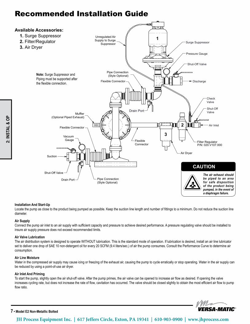
Installation And Start-Up Locatethepumpasclosetotheproductbeingpumpedaspossible.Keepthesuctionlinelengthandnumberoffittingstoaminimum.Donotreducethesuctionlinediameter.
Air Supply Connectthepumpairinlettoanairsupplywithsufficientcapacityandpressuretoachievedesiredperformance.Apressureregulatingvalveshouldbeinstalledtoinsureairsupplypressuredoesnotexceedrecommendedlimits.
Air Valve Lubrication The air distribution system is designed to operate WITHOUT lubrication. This is the standard mode of operation. If lubrication is desired, install an air line lubricator settodeliveronedropofSAE10non-detergentoilforevery20SCFM(9.4liters/sec.)ofairthepumpconsumes.ConsultthePerformanceCurvetodetermineairconsumption.
Air Line Moisture Waterinthecompressedairsupplymaycauseicingorfreezingoftheexhaustair,causingthepumptocycleerraticallyorstopoperating.Waterintheairsupplycanbereducedbyusingapoint-of-useairdryer.
Air Inlet And Priming Tostartthepump,slightlyopentheairshut-offvalve.Afterthepumpprimes,theairvalvecanbeopenedtoincreaseairflowasdesired.Ifopeningthevalveincreasescyclingrate,butdoesnotincreasetherateofflow,cavitationhasoccurred.Thevalveshouldbeclosedslightlytoobtainthemostefficientairflowtopumpflowratio.
Surge Suppressor
Shut-Off Valve
Pressure Gauge
Drain PortShut-OffValve
CheckValve
Air Inlet
Discharge
Unregulated AirSupply to Surge
Suppressor
Pipe Connection(Style Optional)
Flexible Connector
Flexible Connector
VacuumGauge
Suction
Shut-Off Valve
Drain Port Pipe Connection(Style Optional)
FlexibleConnector
Air Dryer
Filter RegulatorP/N: 020.V107.000
Note: Pipe weight should not be supported by pump connections.
Muffler(Optional Piped Exhaust)
recommended Installation Guide
Available Accessories:1. Surge Suppressor2. Filter/Regulator3. Air Dryer
1
2
3
Note: Surge Suppressor and Pipingmustbesupportedaftertheflexibleconnection.
CAUTIONThe air exhaust should be piped to an area for safe disposition of the product being pumped, in the event of a diaphragm failure.
UNIVERSAL ALL AODD
2: IN
STAL
& O
P
JH Process Equipment Inc. | 617 Jeffers Circle, Exton, PA 19341 | 610-903-0900 | www.jhprocess.com

Model E2 Non-Metallic Bolted • 8
recommended Installation Guide Troubleshooting GuideSymptom: Potential Cause(s): Recommendation(s):Pump Cycles Once Deadhead(systempressuremeetsorexceedsair
supply pressure).Increasetheinletairpressuretothepump.Pumpisdesignedfor1:1pressureratioatzeroflow. (Doesnotapplytohighpressure2:1units).
Air valve or intermediate gaskets installed incorrectly. Installgasketswithholesproperlyaligned.Bent or missing actuator plunger. Remove pilot valve and inspect actuator plungers.
Pump Will Not Operate / Cycle
Pumpisoverlubricated. Setlubricatoronlowestpossiblesettingorremove.Unitsaredesignedforlubefreeoperation.Lackofair(linesize,PSI,CFM). Checktheairlinesizeandlength,compressorcapacity(HPvs.cfmrequired).Check air distribution system. Disassembleandinspectmainairdistributionvalve,pilotvalveandpilotvalveactuators.Dischargelineisblockedorcloggedmanifolds. Check for inadvertently closed discharge line valves. Clean discharge manifolds/piping.Deadhead(systempressuremeetsorexceedsairsupply pressure).
Increasetheinletairpressuretothepump.Pumpisdesignedfor1:1pressureratioatzeroflow. (Doesnotapplytohighpressure2:1units).
Blockedairexhaustmuffler. Removemufflerscreen,cleanorde-ice,andre-install.Pumpedfluidinairexhaustmuffler. Disassemblepumpchambers.Inspectfordiaphragmruptureorloosediaphragmplateassembly.Pumpchamberisblocked. Disassembleandinspectwettedchambers.Removeorflushanyobstructions.
Pump Cycles and Will Not Prime or No Flow
Cavitation on suction side. Check suction condition (move pump closer to product).Check valve obstructed. Valve ball(s) not seating properly or sticking.
Disassemblethewetendofthepumpandmanuallydislodgeobstructioninthecheckvalvepocket. Clean out around valve ball cage and valve seat area. Replace valve ball or valve seat if damaged. Use heavier valve ball material.
Valve ball(s) missing (pushed into chamber or manifold).
Wornvalveballorvalveseat.Wornfingersinvalveballcage(replacepart).CheckChemical Resistance Guide for compatibility.
Valve ball(s)/seat(s) damaged or attacked by product. Check Chemical Resistance Guide for compatibility.Checkvalveand/orseatiswornorneedsadjusting. Inspectcheckvalvesandseatsforwearandpropersetting.Replaceifnecessary.Suction line is blocked. Removeorflushobstruction.Checkandclearallsuctionscreensorstrainers.Excessivesuctionlift. Forliftsexceeding20’ofliquid,fillingthechamberswithliquidwillprimethepumpinmostcases.Suction side air leakage or air in product. Visuallyinspectallsuction-sidegasketsandpipeconnections.Pumpedfluidinairexhaustmuffler. Disassemblepumpchambers.Inspectfordiaphragmruptureorloosediaphragmplateassembly.
Pump Cycles Running Sluggish/Stalling, Flow Unsatisfactory
Over lubrication. Setlubricatoronlowestpossiblesettingorremove.Unitsaredesignedforlubefreeoperation.Icing. Removemufflerscreen,de-ice,andre-install.Installapointofuseairdrier.Clogged manifolds. CleanmanifoldstoallowproperairflowDeadhead(systempressuremeetsorexceedsairsupply pressure).
Increasetheinletairpressuretothepump.Pumpisdesignedfor1:1pressureratioatzeroflow. (Doesnotapplytohighpressure2:1units).
Cavitation on suction side. Check suction (move pump closer to product).Lackofair(linesize,PSI,CFM). Check the air line size, length, compressor capacity.Excessivesuctionlift. Forliftsexceeding20’ofliquid,fillingthechamberswithliquidwillprimethepumpinmostcases.Airsupplypressureorvolumeexceedssystemhd. Decreaseinletair(press.andvol.)tothepump.Pumpiscavitatingthefluidbyfastcycling.Undersized suction line. Meetorexceedpumpconnections.Restrictive or undersized air line. Install a larger air line and connection. Suction side air leakage or air in product. Visuallyinspectallsuction-sidegasketsandpipeconnections.Suction line is blocked. Removeorflushobstruction.Checkandclearallsuctionscreensorstrainers.Pumpedfluidinairexhaustmuffler. Disassemblepumpchambers.Inspectfordiaphragmruptureorloosediaphragmplateassembly.Check valve obstructed. Disassemblethewetendofthepumpandmanuallydislodgeobstructioninthecheckvalvepocket.Checkvalveand/orseatiswornorneedsadjusting. Inspectcheckvalvesandseatsforwearandpropersetting.Replaceifnecessary.Entrainedairorvaporlockinchamber(s). Purgechambersthroughtappedchamberventplugs.Purgingthechambersofaircanbedangerous.
Product Leaking Through Exhaust
Diaphragmfailure,ordiaphragmplatesloose. Replace diaphragms, check for damage and ensure diaphragm plates are tight.Diaphragmstretchedaroundcenterholeorboltholes. Checkforexcessiveinletpressureorairpressure.ConsultChemicalResistanceChartforcompatibility
withproducts,cleaners,temperaturelimitationsandlubrication.Premature Diaphragm Failure
Cavitation. Enlargepipediameteronsuctionsideofpump.Excessivefloodedsuctionpressure. Movepumpclosertoproduct.Raisepump/placepumpontopoftanktoreduceinletpressure.
Install Back pressure device (Tech bulletin 41r). Add accumulation tank or pulsation dampener.Misapplication(chemical/physicalincompatibility). ConsultChemicalResistanceChartforcompatibilitywithproducts,cleaners,temperaturelimitations
and lubrication.Incorrectdiaphragmplatesorplatesonbackwards,installedincorrectlyorworn.
CheckOperatingManualtocheckforcorrectpartandinstallation.Ensureouterplateshavenotbeenworntoasharpedge.
Unbalanced Cycling Excessivesuctionlift. Forliftsexceeding20’ofliquid,fillingthechamberswithliquidwillprimethepumpinmostcases.Undersized suction line. Meetorexceedpumpconnections.Pumpedfluidinairexhaustmuffler. Disassemblepumpchambers.Inspectfordiaphragmruptureorloosediaphragmplateassembly.Suction side air leakage or air in product. Visuallyinspectallsuction-sidegasketsandpipeconnections.Check valve obstructed. Disassemblethewetendofthepumpandmanuallydislodgeobstructioninthecheckvalvepocket.Checkvalveand/orseatiswornorneedsadjusting. Inspectcheckvalvesandseatsforwearandpropersetting.Replaceifnecessary.Entrainedairorvaporlockinchamber(s). Purgechambersthroughtappedchamberventplugs.
For additional troubleshooting tips contact After Sales Support at [email protected] or 419-524-8388
UNIVERSAL ALL AODD, EXCEPT FLAP
2: IN
STAL
& O
P
JH Process Equipment Inc. | 617 Jeffers Circle, Exton, PA 19341 | 610-903-0900 | www.jhprocess.com

9 • Model E2 Non-Metallic Bolted
Composite repair Parts drawing - Elastomeric and TPE fitted
2
3
4
5
6
7
8
910
11
11
12
14
15
16
17
18
1920
21
22
23
24
25
26
27
28
29
30
31
31
32
33
34
35
37
38
40
40
36
43
13
DISCHARGE CENTER PORT MANIFOLDASSEMBLY
44
45
46
46
47
47
50
50 42
SUCTION CENTER PORT MANIFOLDASSEMBLY
49
48
49
48
39
392
3
4
5
6
7
8
910
11
11
12
14
15
16
17
18
1920
21
22
23
24
25
26
27
28
29
30
31
31
32
33
34
35
37
38
40
40
36
43
13
DISCHARGE CENTER PORT MANIFOLDASSEMBLY
44
45
46
46
47
47
50
50 42
SUCTION CENTER PORT MANIFOLDASSEMBLY
49
48
49
48
39
39
2
3
4
5
6
7
8
910
11
11
12
14
15
16
17
18
1920
21
22
23
24
25
26
27
28
29
30
31
31
32
33
34
35
37
38
40
40
36
43
13
DISCHARGE CENTER PORT MANIFOLDASSEMBLY
44
45
46
46
47
47
50
50 42
SUCTION CENTER PORT MANIFOLDASSEMBLY
49
48
49
48
39
39
General Model Specific
3: E
XP V
IEW
JH Process Equipment Inc. | 617 Jeffers Circle, Exton, PA 19341 | 610-903-0900 | www.jhprocess.com
Model E2 Non-Metallic Bolted • 10
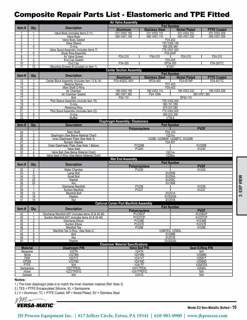
Notes:1.)Theinnerdiaphragmplateistomatchtheinnerchambermaterial(Ref.Note3)2.)TES=PTFEEncapsulatedSilicone,XL=Santoprene3.)V=Aluminum,TC=PTFECoated,NP=NickelPlated,SV=StainlessSteel
Composite repair Parts list - Elastomeric and TPE fittedAir Valve Assembly
Item # Qty. Description Part NumberAluminum Stainless Steel Nickel Plated PTFE Coated
1 1 ValveBody(includesitems2-11) 031.V002.156 031.V002.110 031.V002.332 031.V002.3092 1 Valve Body 095.V001.156 095.V001.110 095.V001.332 095.V001.3093 1 Valve Body Gasket P24-2024 1 Valve Sleeve 755.V006.1485 6 O-ring 560.206.3606 1 ValveSpoolAssembly(Includesitems7) 775.V001.0007 6 Glyde Ring Assembly P34-204F8 1 Air Valve Screen P24-210 P34-210 P24-210 P24-2109 2 EndCapGasket P24-20510 2 EndCap P34-300 SP34-300 P34-300TC11 13 MountingScrews(8includedonitem1) S1001
Center Section AssemblyItem # Qty. Description Part Number
Aluminum Stainless Steel Nickel Plated PTFE Coated12 1 Center Block Assembly (Includes item 13 & 14) P24-400DCASY SP24-400 P24-401NP P24-401TC13 2 Bearing Sleeve P31-40314 2 MainShaftO-Ring P24-40315 2 Air Chamber 196.V003.156 196.V003.110 196.V003.332 196.V003.30916 2 Air Chamber Gasket 360.V001.360 P24-109A 360.V001.36017 8 Bolt P24-110 SP24-11018 1 PilotSleeveAssembly(includeitem19) 755.V002.00019 6 O-ring 560.101.35820 1 Retaining Ring 675.037.08021 1 PilotSpoolAssembly(Includesitem22) 775.V002.00022 8 O-ring 560.023.35823 1 Muffler VTM-8
Diaphragm Assembly / ElastomersItem # Qty. Description Part Number
Polypropylene PVDF24 1 MainShaft P24-10325 2 Diaphragm(SeeBelowMaterialChart) V227xx26 2 InnerDiaphragmPlate(SeeNote3) V226B,V226BNP,V226BTC,SV226B27 2 Bumper Washer P24-50128 2 OuterDiaphragmPlate(SeeNote1Below) PV226B KV226B29 4 Valve Seat PV240 KV24030 4 ValveBall(SeeBelowMaterialChart) V241xx31 8 ValveSeatO-Ring(SeeBelowMaterialChart) V258xx
Wet End AssemblyItem # Qty. Description Part Number
Polypropylene PVDF32 2 Water Chamber PV235 KV23533 8 LargeBolt SV250B34 12 Small Bolt SV250A35 20 Washer SV250C36 20 Nut SV185B37 1 DischargeManifold PV236 KV23638 1 SuctionManifold PV237 KV23739 16 ManifoldBolt SV251A40 16 Washer SV302GA41 16 Nut SV251B
Optional Center Port Manifold AssemblyItem # Qty. Description Part Number
Polypropylene PVDF42 1 DischargeManifoldASY(includesitems43&45-49) PV236CP KV236CP43 1 SuctionManifoldASY(includesitems42&45-49) PV237CP KV237CP44 2 DischargeElbow PV236E KV236E45 2 SuctionElbow PV237E KV237E46 2 ManifoldTee PV288 KV28847 4 ManifoldTeeO-Ring(SeeNote2) V288TES,V258XL48 8 Bolt SV288B49 8 Nut SV251B50 8 Washer SV302GA
Elastomer Material SpecificationsMaterial Diaphragm P/N Valve Ball P/N Seat O-Ring P/NNeoprene V227N V241N N/ANitrile V227BN V241BN V258BNFKM V227VT V241VT V258VTEPDM V227ND V241ND V258NDPTFE N/A V241TF V258TES
Santoprene V227TPEXL V241TPEXL V258XLHytrel V227TPEFG V241TPEFG N/A
Geolast N/A V241G N/A
MODEL SPECIFIC
3: E
XP V
IEW
JH Process Equipment Inc. | 617 Jeffers Circle, Exton, PA 19341 | 610-903-0900 | www.jhprocess.com

11 • Model E2 Non-Metallic Bolted
2
3
4
5
6
7
8
910
11
11
12
14
15
16
17
18
1920
21
22
23
24
27
28
29
26
31
32
33
33
34
35
36
37
39
40
41
41
42
42
43
30
25
38
SUCTION CENTER PORT MANIFOLDASSEMBLY
13
DISCHARGE CENTER PORT MANIFOLDASSEMBLY
48
48
45
4450
51
52
50
52
51
49
46
49
47
FUSION DIAPHRAGMASSEMBLY
26
24
29
2
3
4
5
6
7
8
910
11
11
12
14
15
16
17
18
1920
21
22
23
24
27
28
29
26
31
32
33
33
34
35
36
37
39
40
41
41
42
42
43
30
25
38
SUCTION CENTER PORT MANIFOLDASSEMBLY
13
DISCHARGE CENTER PORT MANIFOLDASSEMBLY
48
48
45
4450
51
52
50
52
51
49
46
49
47
FUSION DIAPHRAGMASSEMBLY
26
24
29
2
3
4
5
6
7
8
910
11
11
12
14
15
16
17
18
1920
21
22
23
24
27
28
29
26
31
32
33
33
34
35
36
37
39
40
41
41
42
42
43
30
25
38
SUCTION CENTER PORT MANIFOLDASSEMBLY
13
DISCHARGE CENTER PORT MANIFOLDASSEMBLY
48
48
45
4450
51
52
50
52
51
49
46
49
47
FUSION DIAPHRAGMASSEMBLY
26
24
29
2
3
4
5
6
7
8
910
11
11
12
14
15
16
17
18
1920
21
22
23
24
27
28
29
26
31
32
33
33
34
35
36
37
39
40
41
41
42
42
43
30
25
38
SUCTION CENTER PORT MANIFOLDASSEMBLY
13
DISCHARGE CENTER PORT MANIFOLDASSEMBLY
48
48
45
4450
51
52
50
52
51
49
46
49
47
FUSION DIAPHRAGMASSEMBLY
26
24
29
Composite repair Parts drawing - PTfE fitted3:
EXP
VIE
W
JH Process Equipment Inc. | 617 Jeffers Circle, Exton, PA 19341 | 610-903-0900 | www.jhprocess.com

Model E2 Non-Metallic Bolted • 12
Notes:1.) The inner diaphragm plate is to match the inner chamber materialV=Aluminum,TC=PTFECoated,NP=NickelPlated,SV=StainlessSteel
Air Valve AssemblyItem # Qty. Description Part Number
Aluminum Stainless Steel Nickle Plated PTFE Coated1 1 ValveBody(includesitems2-11) 031.V002.156 031.V002.110 031.V002.332 031.V002.3092 1 Valve Body 095.V001.156 095.V001.110 095.V001.332 095.V001.3093 1 Valve Body Gasket P24-2024 1 Valve Sleeve 755.V006.1485 6 O-ring 560.206.3606 1 ValveSpoolAssembly(Includesitems7) 775.V001.0007 6 Glyde Ring Assembly P34-204F8 1 Air Valve Screen P24-210 P34-210 P24-210 P24-2109 2 EndCapGasket P24-205
10 2 EndCap P34-300 SP34-300 P34-300TC11 13 MountingScrews(8includedonitem1) S1001
Center Section AssemblyItem # Qty. Description Part Number
Aluminum Stainless Steel Nickle Plated PTFE Coated12 1 Center Block Assembly (Includes item 13 & 14) P24-400DCASY SP24-400 P24-401NP P24-401TC13 2 Bearing Sleeve P31-40314 2 MainShaftO-Ring P24-40315 2 Air Chamber 196.V003.156 196.V003.110 196.V003.332 196.V003.30916 2 Air Chamber Gasket 360.V001.360 P24-109A 360.V001.36017 8 Bolt P24-110 SP24-11018 1 PilotSleeveAssembly(includeitem19) 755.V002.00019 6 O-ring 560.101.35820 1 Retaining Ring 675.037.08021 1 PilotSpoolAssembly(Includesitem22) 775.V002.00022 8 O-ring 560.023.35823 1 Muffler VTM-8
Diaphragm Assembly / ElastomersItem # Qty. Description Part Number
PTFE Two Peice FusionPolyproylene PVDF Polyproylene PVDF
24 1 MainShaft P24-102 P24-103F25 2 Shaft Stud V221F N/A26 2 Diaphragm V227TF V227F27 2 Back-UpDiaphragm V227TFB N/A28 2 InnerDiaphragmPlate V221TI,V221TINP,V221TITC,SV221TI N/A29 2 Bumper Washer P24-50130 2 OuterDiaphragmPlate PV221TO KV221TO N/A31 4 Valve Seat PV240 KV240 PV240 KV24032 4 Valve Ball V241TF33 8 ValveSeatO-Ring V258TES
Wet End AssemblyItem # Qty. Description Part Number
Polyproylene PVDF34 2 Water Chamber PV235 KV23535 8 LargeBolt SV250B36 12 Small Bolt SV250A37 20 Washer SV250C38 20 Nut SV185B39 1 DischargeManifold PV236 KV23640 1 SuctionManifold PV237 KV23741 16 ManifoldBolt SV251A42 16 Washer SV302GA43 16 Nut SV251B
Optional Center Port Manifold AssemblyItem # Qty. Description Part Number
Polypropylene PVDF44 1 DischargeManifoldASY(includesitems46&48-52) PV236CP KV236CP45 1 SuctionManifoldASY(includesitems47&48-52) PV237CP KV237CP46 2 DischargeElbow PV236E KV236E47 2 SuctionElbow PV237E KV237E48 2 ManifoldTee PV288 KV28849 4 ManifoldTeeO-Ring V288TES,V258XL50 8 Bolt SV288B51 8 Nut SV251B52 8 Washer SV302GA
Composite repair Parts list - PTfE fitted
3: E
XP V
IEW
JH Process Equipment Inc. | 617 Jeffers Circle, Exton, PA 19341 | 610-903-0900 | www.jhprocess.com
13 • Model E2 Non-Metallic Bolted
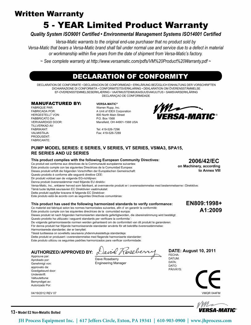
written warranty5 - yEar limited Product warranty
Quality System ISO9001 Certified • Environmental Management Systems ISO14001 Certified Versa-Matic warrants to the original end-use purchaser that no product sold by
Versa-Matic that bears a Versa-Matic brand shall fail under normal use and service due to a defect in materialor workmanship within five years from the date of shipment from Versa-Matic’s factory.
~ See complete warranty at http://www.versamatic.com/pdfs/VM%20Product%20Warranty.pdf ~
DATE: August 10, 2011FECHA: DATUM:DATA:DATO:PÄIVÄYS:
AUTHORIZED / APPROVED BY: Approuve par: Aprobado por: Genehmigt von: approvato da: Goedgekeurd door: Underskrift: Valtuutettuna: Bemyndiget av: Autorizado Por:
04/19/2012 REV 07 VMQR 044FM
This product complies with the following European Community Directives: Ce produit est conforme aux directives de la Communauté européenne suivantes: Este producto cumple con las siguientes Directrices de la Comunidad Europea: Dieses produkt erfüllt die folgenden Vorschriften der Europäischen Gemeinschaft: Questo prodotto è conforme alle seguenti direttive CEE: Dir produkt voldoet aan de volgende EG-richtlijnen: Denna produkt överensstämmer med följande EU direktiv: Versa-Matic, Inc., erklærer herved som fabrikant, at ovennævnte produkt er i overensstemmelse med bestemmelserne i Direkktive:Tämä tuote täyttää seuraavien EC Direktiivien vaatimukstet:Dette produkt oppfyller kravene til følgende EC Direktiver:Este produto está de acordo com as seguintes Directivas comunitárias:
MANUFACTURED BY:FABRIQUE PAR:FABRICADA POR:HERGESTELLT VON:FABBRICATO DA:VERVAARDIGD DOOR:TILLVERKAD AV:FABRIKANT:VALMISTAJA:PRODUSENT:FABRICANTE:
DECLARATION DE CONFORMITE • DECLARACION DE CONFORMIDAD • ERKLÄRUNG BEZÜGLICH EINHALTUNG DER VORSCHRIFTENDICHIARAZIONE DI CONFORMITÀ • CONFORMITEITSVERKLARING • DEKLARATION OM ÖVERENSSTÄMMELSE
EF-OVERENSSTEMMELSESERKLÆRING • VAATIMUSTENMUKAISUUSVAKUUTUS • SAMSVARSERKLÄRING DECLARAÇAO DE CONFORMIDADE
VERSA-MATIC®
Warren Rupp, Inc.A Unit of IDEX Corporation 800 North Main Street P.O. Box 1568 Mansfield, OH 44901-1568 USA
Tel: 419-526-7296Fax: 419-526-7289
This product has used the following harmonized standards to verify conformance: EN809:1998+A1:2009Ce materiel est fabriqué selon les normes harmonisées suivantes, afin d’ en garantir la conformité:
Este producto cumple con las siquientes directrices de la comunidad europa:Dieses produkt ist nach folgenden harmonisierten standards gefertigtworden, die übereinstimmung wird bestätigt:Questo prodotto ha utilizzato i seguenti standards per verificare la conformita´:De volgende geharmoniseerde normen werden gehanteerd om de conformiteit van dit produkt te garanderen: För denna produkt har följande harmoniserande standarder använts för att bekräfta överensstämmelse:Harmoniserede standarder, der er benyttet:Tässä tuotteessa on sovellettu seuraavia yhdenmukaistettuja standardeja:Dette produkt er produsert i overenstemmelse med fløgende harmoniserte standarder:Este produto utilizou os seguintes padrões harmonizados para varificar conformidade:
PUMP MODEL SERIES: E SERIES, V SERIES, VT SERIES, VSMA3, SPA15, RE SERIES AND U2 SERIES
Dave RoseberryEngineering Manager
DECLARATION OF CONFORMITY
2006/42/ECon Machinery, according
to Annex VIII
MODEL SPECIFIC
JH Process Equipment Inc. | 617 Jeffers Circle, Exton, PA 19341 | 610-903-0900 | www.jhprocess.com