Embed Size (px)
Citation preview
The Drive & Control Company
Compact Modules CKLwith Ball Rail Systems and Linear Motor
RE 82 617/2003-05
RE 82 617/2003-05 2
Rexroth Linear Motion Technology
Ball Rail Systems Standard Ball Rail SystemsSuper Ball Rail SystemsBall Rail Systems with Aluminum Runner BlocksHigh Speed Ball Rail SystemsCorrosion-Resistant Ball Rail SystemsWide Ball Rail Systems
Ball Rail Systems with Integrated Measuring SystemBraking and Clamping Units for Ball Rail SystemsRack and Pinion Drives for Ball Rail SystemsMiniature Ball Rail SystemsCam Roller Guides
Roller Rail Systems Standard Roller Rail SystemsWide Roller Rail SystemsHeavy Duty Roller Rail SystemsRoller Rail Systems with Integrated Measuring SystemBraking and Clamping Units for Roller Rail SystemsRack and Pinion Drives for Roller Rail Systems
Linear Bushings and Shafts Linear Bushings, Linear SetsShafts, Shaft Support Rails, Shaft Support Blocks
Ball Transfer UnitsTraditional Engineering Components
Screw Drives
Linear Motion Systems Linear Motion Slides – Ball Screw Drive– Toothed Belt Drive
Linear Modules – Ball Screw Drive– Toothed Belt Drive– Rack and Pinion Drive– Pneumatic Drive– Linear Motor
Compact Modules – Linear Motor
– Ball Screw Drive– Toothed Belt Drive
Precision Modules – Ball Screw Drive
Ball Rail Tables – Ball Screw Drive– Linear Motor
Controllers, Motors – Servomotors
Electrical Accessories – Three-phase Motors, Stepping Motors
Linear Actuators
3 RE 82 617/2003-05
Compact Modules CKL with Linear Motor
Product Overview 4
Structure 7
Technical Data 8
Mounting 11
CKL 7-90 12Components and Ordering Data 12Dimension Drawings 14
CKL 9-110 16Components and Ordering Data 16Dimension Drawings 18
CKL 15-145 20Components and Ordering Data 20Dimension Drawings 22
Linear Motor 24
Linear Encoder 26
Digital Servo Controller DSC 28Technical Data 29
Documentation 30
Inquiry / Order Form 31
RE 82 617/2003-05 4
Compact Modules CKL with Linear Motor
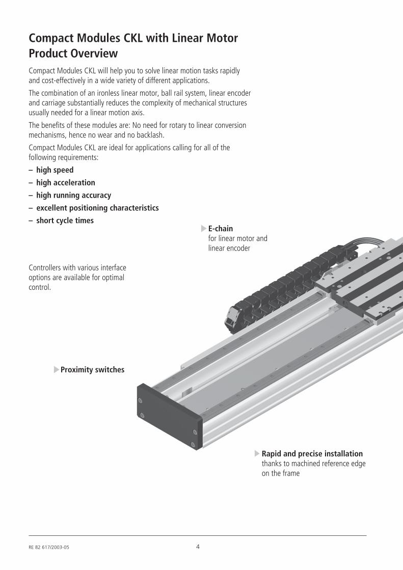
Compact Modules CKL will help you to solve linear motion tasks rapidlyand cost-effectively in a wide variety of different applications.
The combination of an ironless linear motor, ball rail system, linear encoderand carriage substantially reduces the complexity of mechanical structuresusually needed for a linear motion axis.
The benefits of these modules are: No need for rotary to linear conversionmechanisms, hence no wear and no backlash.
Compact Modules CKL are ideal for applications calling for all of thefollowing requirements:
– high speed
– high acceleration
– high running accuracy
– excellent positioning characteristics
– short cycle timesE-chainfor linear motor andlinear encoder
Proximity switches
Product Overview
Controllers with various interfaceoptions are available for optimalcontrol.
Rapid and precise installationthanks to machined reference edgeon the frame

5 RE 82 617/2003-05
High positioning accuracyand repeatabilitydue to precise optical positionsensor
Easy maintenanceof the ball rail system due toone-point lubrication; linearmotor maintenance-free
Rapid mountingusing clamping fixturesor tap holes in frame
High speed and highaccelerationdue to excellent dynamic ofthe ironless linear motor
Carriageavailable in various lengths
Servocontroller DSCcomes withparameter fileson CD for easyparametrization
RE 82 617/2003-05 6
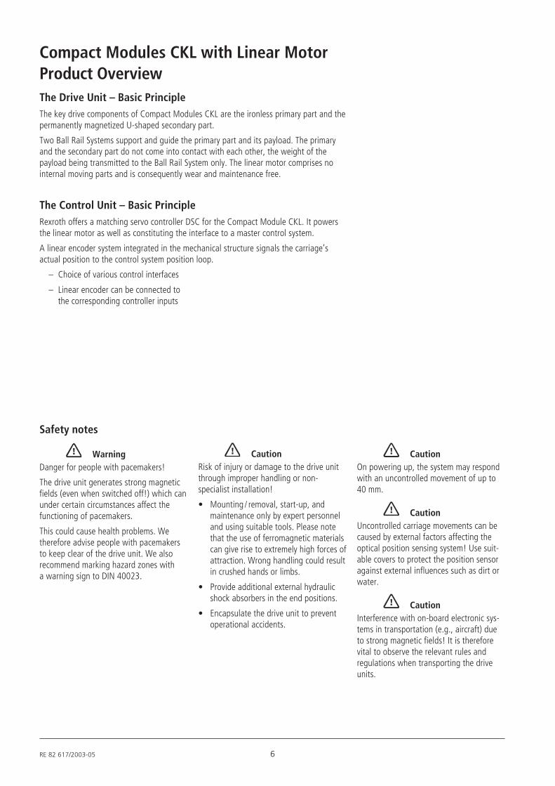
Compact Modules CKL with Linear MotorProduct OverviewThe Drive Unit – Basic PrincipleThe key drive components of Compact Modules CKL are the ironless primary part and thepermanently magnetized U-shaped secondary part.
Two Ball Rail Systems support and guide the primary part and its payload. The primaryand the secondary part do not come into contact with each other, the weight of thepayload being transmitted to the Ball Rail System only. The linear motor comprises nointernal moving parts and is consequently wear and maintenance free.
The Control Unit – Basic PrincipleRexroth offers a matching servo controller DSC for the Compact Module CKL. It powersthe linear motor as well as constituting the interface to a master control system.
A linear encoder system integrated in the mechanical structure signals the carriage’sactual position to the control system position loop.
– Choice of various control interfaces
– Linear encoder can be connected tothe corresponding controller inputs
Safety notes
WarningDanger for people with pacemakers!
The drive unit generates strong magneticfields (even when switched off!) which canunder certain circumstances affect thefunctioning of pacemakers.
This could cause health problems. Wetherefore advise people with pacemakersto keep clear of the drive unit. We alsorecommend marking hazard zones witha warning sign to DIN 40023.
CautionRisk of injury or damage to the drive unitthrough improper handling or non-specialist installation!
• Mounting / removal, start-up, andmaintenance only by expert personneland using suitable tools. Please notethat the use of ferromagnetic materialscan give rise to extremely high forces ofattraction. Wrong handling could resultin crushed hands or limbs.
• Provide additional external hydraulicshock absorbers in the end positions.
• Encapsulate the drive unit to preventoperational accidents.
CautionOn powering up, the system may respondwith an uncontrolled movement of up to40 mm.
CautionUncontrolled carriage movements can becaused by external factors affecting theoptical position sensing system! Use suit-able covers to protect the position sensoragainst external influences such as dirt orwater.
CautionInterference with on-board electronic sys-tems in transportation (e.g., aircraft) dueto strong magnetic fields! It is thereforevital to observe the relevant rules andregulations when transporting the driveunits.
7 RE 82 617/2003-05
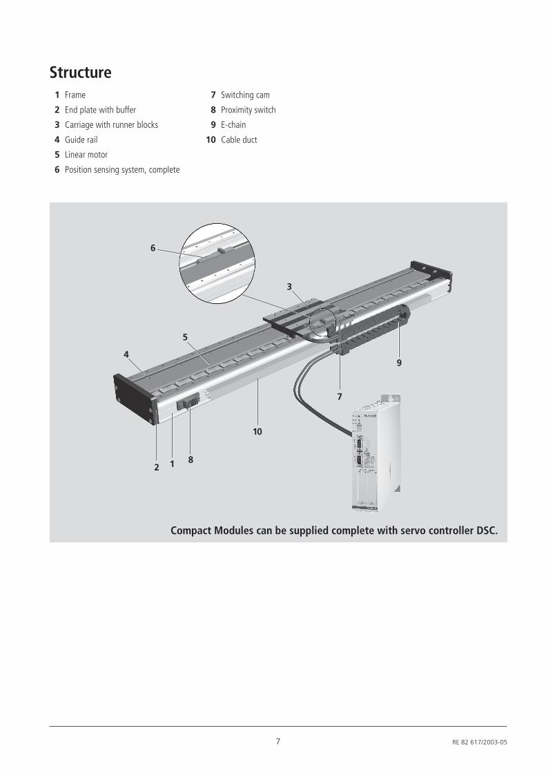
Structure1 Frame
2 End plate with buffer
3 Carriage with runner blocks
4 Guide rail
5 Linear motor
6 Position sensing system, complete
1
Compact Modules can be supplied complete with servo controller DSC.
7 Switching cam
8 Proximity switch
9 E-chain
10 Cable duct
28
5
7
9
3
6
4
10

RE 82 617/2003-05 8
Compact Modules CKL with Linear MotorTechnical Data
E = 70,000 N/mm2Modulus of elasticity E
General technical dataLoad capacities and moments
Compact Carriage Motor Dynamic Dynamic Maximum Maximum Continuous Maximum permissible
Module length type load capacity moments length thrust thrust forces
Mt ML Lmax Fmax Mtmax MLmax
(mm) (N) (Nm) (Nm) (mm) (N) (N) (N) (Nm) (Nm)
CKL 7-90
CKL 9-110
CKL15-145
140
200
160
220
180
240
305
365
LM110-1
LM110-2
LM210-2
LM210-3
LM310-2
LM310-3
LM310-4
LM310-5
2794
3834
13646
100
165
760
160
240
200
310
750
1160
1570
1980
2500
2800
2800
108
202
255
375
410
600
788
980
24
45
57
84
91
134
176
219
The dynamic load capacities and momentsare based on 100,000 m travel.However, a travel of just 50,000 m is oftentaken as a basis.If this is the case, for comparison purposes:
Multiply value C, Mt and ML from the tableby 1.26.
Note on dynamic load capacities andmoments
As far as the desired service life is con-cerned, loads of up to approximately 10%of the dynamic characteristics have provedacceptable.
Suitable loads With a side load above 8%, it should betaken into account when considering theservice life that only one rail is securedlaterally.
ML
Cy
Mt
MLCx
Cx
The dynamic load capacities and moments are required for calculating the nominal life.
1950
2300
7290
69
100
406
110
165
120
185
390
610
810
1000
9 RE 82 617/2003-05
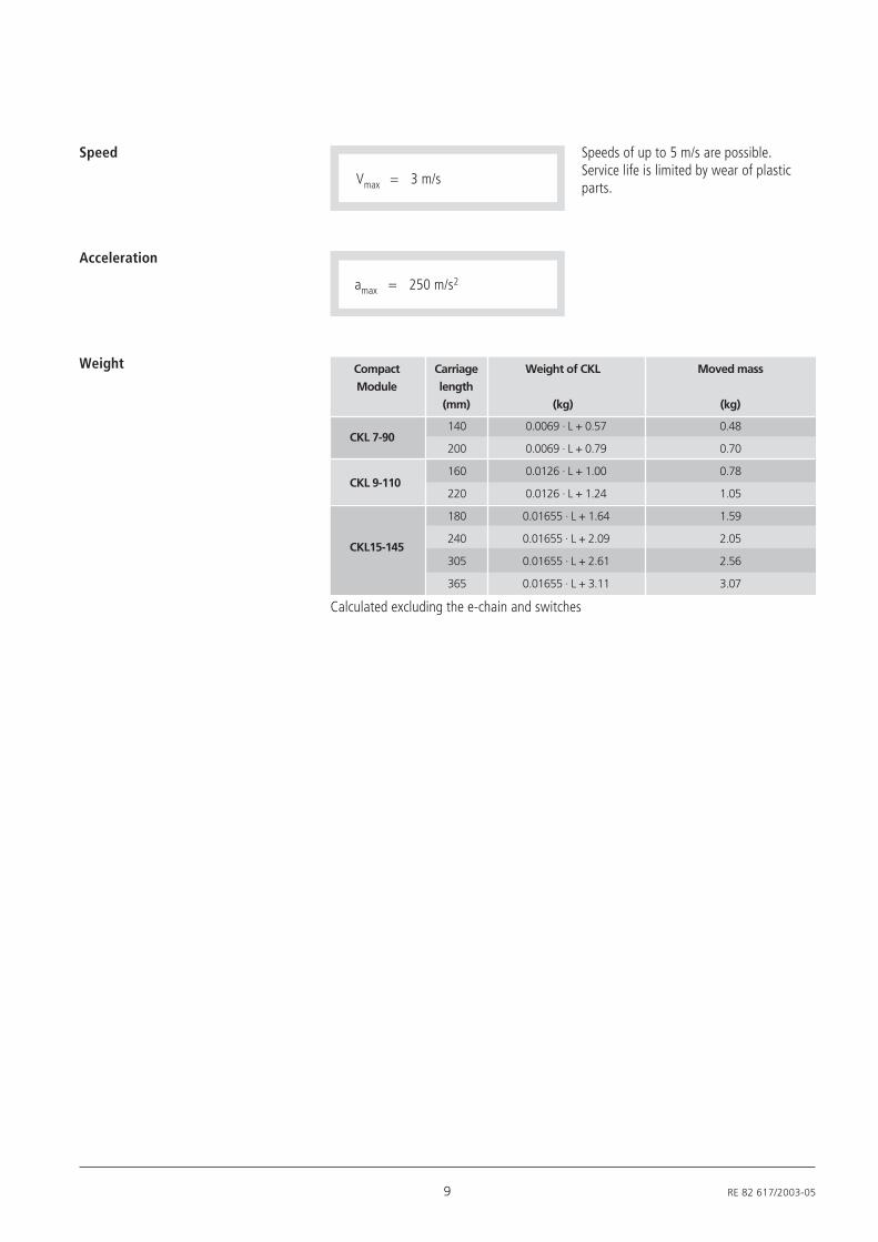
Speeds of up to 5 m/s are possible.Service life is limited by wear of plasticparts.
Speed
Vmax = 3 m/s
Acceleration
amax = 250 m/s2
Weight
Calculated excluding the e-chain and switches
Compact Carriage Weight of CKL Moved mass
Module length
(mm) (kg) (kg)
CKL 7-90
CKL 9-110
CKL15-145
140
200
160
220
180
240
305
365
0.0069 · L + 0.57
0.0069 · L + 0.79
0.0126 · L + 1.00
0.0126 · L + 1.24
0.01655 · L + 1.64
0.01655 · L + 2.09
0.01655 · L + 2.61
0.01655 · L + 3.11
0.48
0.70
0.78
1.05
1.59
2.05
2.56
3.07
RE 82 617/2003-05 10
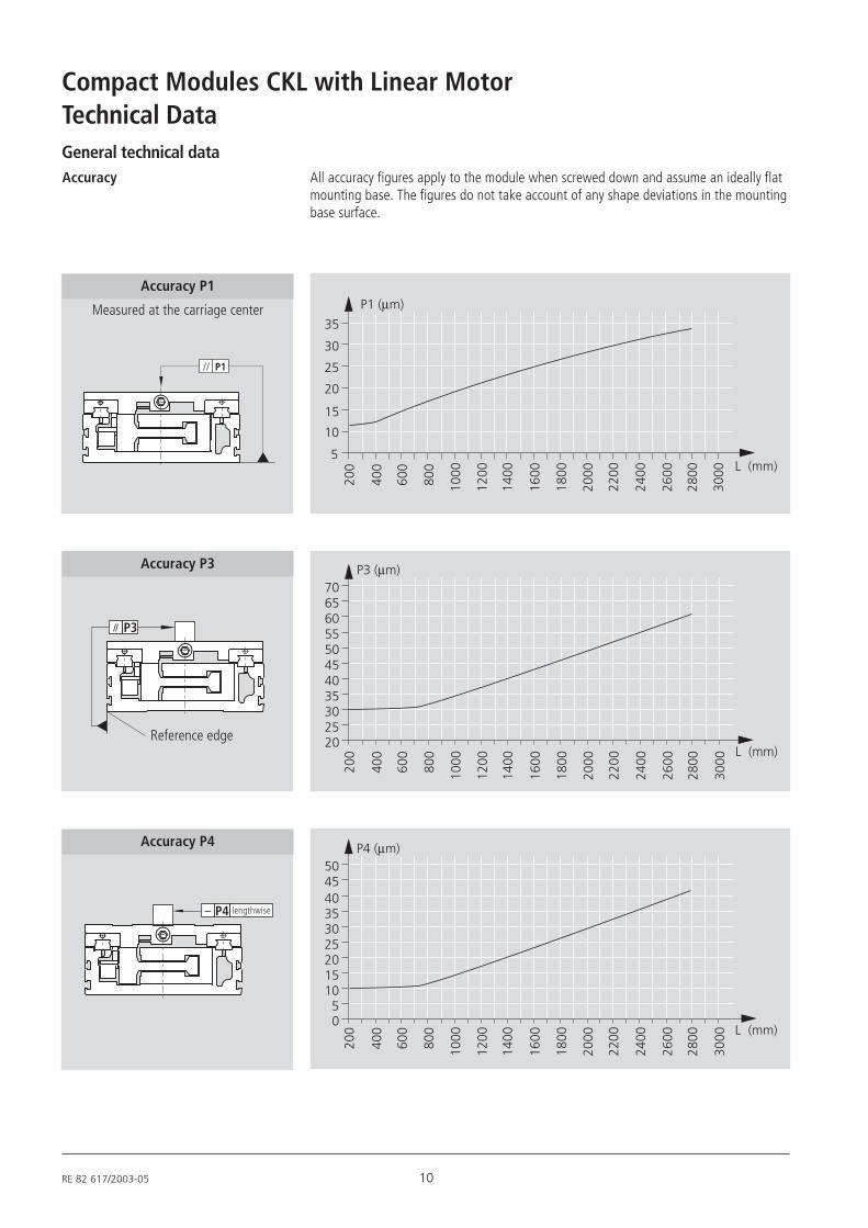
Compact Modules CKL with Linear MotorTechnical DataGeneral technical dataAccuracy All accuracy figures apply to the module when screwed down and assume an ideally flat
mounting base. The figures do not take account of any shape deviations in the mountingbase surface.
P1
Accuracy P1
Measured at the carriage center P1 (µm)
5
10
15
20
25
30
35
200
400
600
800
1000
1200
1600
1800
2000
2200
2400
2600
2800
3000 L (mm)
1400
P3 (µm)
L (mm)20
200
400
600
800
1000
1200
1600
1800
2000
2200
2400
2600
2800
3000
1400
70656055504540353025
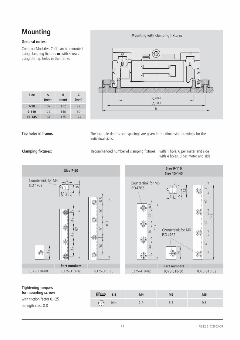
Accuracy P3
P3
Reference edge
P4 (µm)
L (mm)0
200
400
600
800
1000
1200
1600
1800
2000
2200
2400
2600
2800
3000
1400
403530252015105
5045
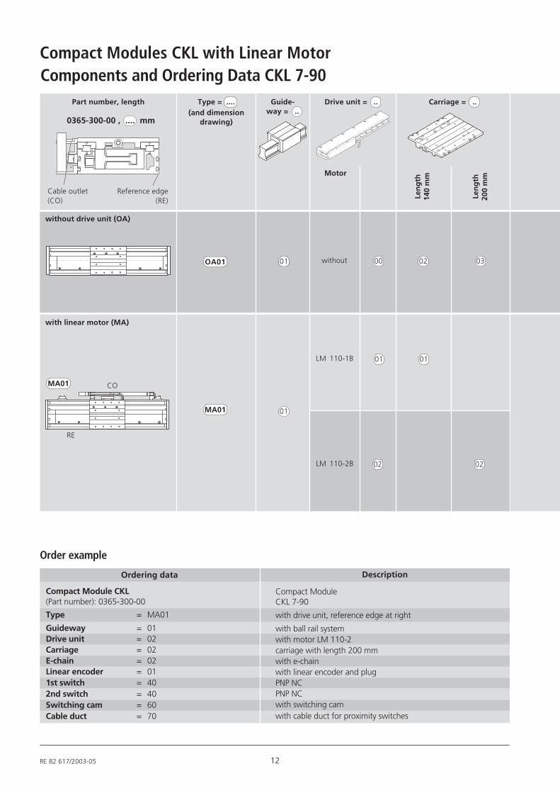
Accuracy P4
P4 lengthwise
11 RE 82 617/2003-05
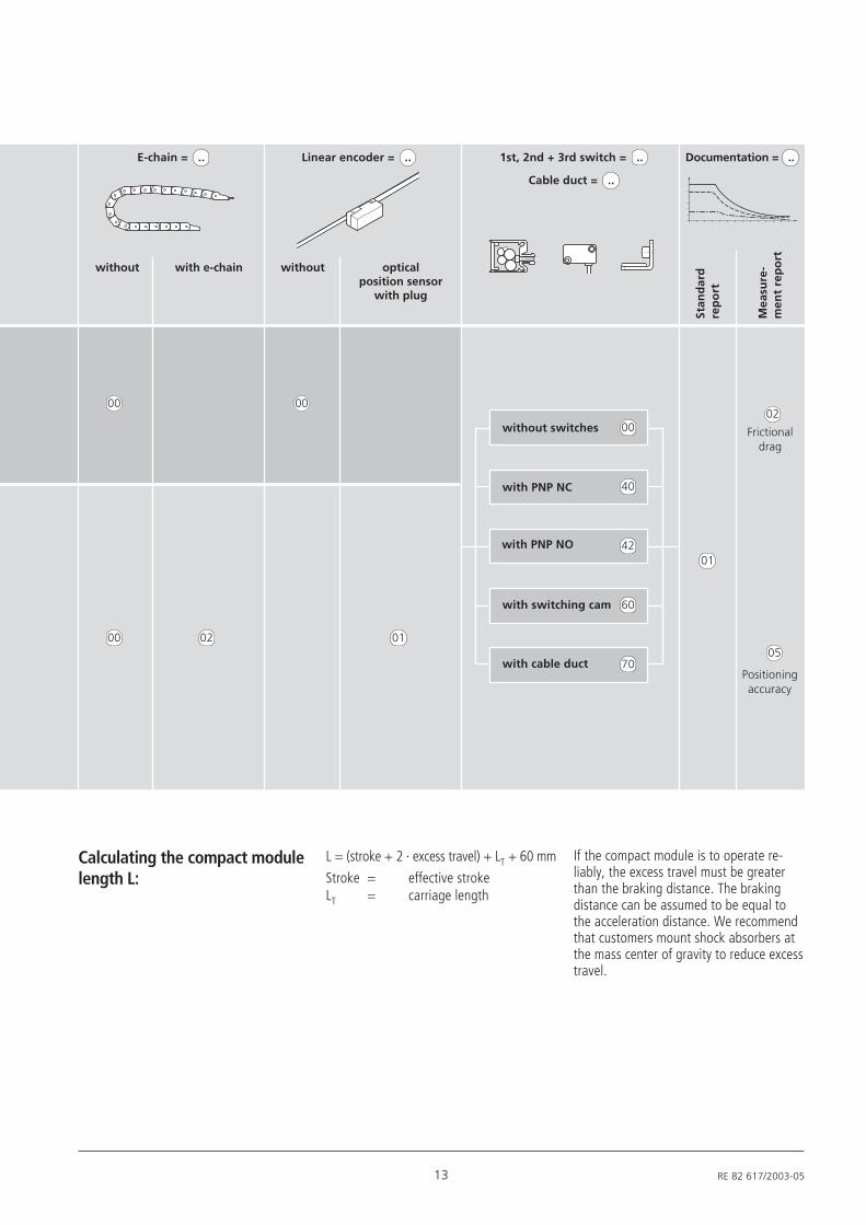
Mounting
Compact Modules CKL can be mountedusing clamping fixtures or with screwsusing the tap holes in the frame.
General notes:25
625
2525
87
8.5
3030
30
107
4.6
9
5
14.5
Clamping fixtures: Recommended number of clamping fixtures: with 1 hole, 6 per meter and sidewith 4 holes, 3 per meter and side
Tightening torquesfor mounting screws
with friction factor 0.125
strength class 8.8
0375-310-00
8.8 M4 M5 M6
Nm 2.7 5.5 9.5
Size 9-110Size 15-145
Size 7-90
Mounting with clamping fixtures
Size A B C
(mm) (mm) (mm)
7-90 102 112 72
9-110 126 140 80
15-145 161 175 124
0375-310-02
Part numbers0375-310-03
Countersink for M4ISO 4762
Tap holes in frame: The tap hole depths and spacings are given in the dimension drawings for theindividual sizes.
B
C ± 0.1
A ± 0.1
5.5
11.5
8.5
3030
30
107
1140
4040
142
25
7
19.3
0375-510-000375-410-02Part numbers
0375-510-02
Countersink for M6ISO 4762
Countersink for M5ISO 4762
RE 82 617/2003-05 12
Compact Modules CKL with Linear MotorComponents and Ordering Data CKL 7-90
without drive unit (OA)
Motor
Len
gth
200
mm
OA01
MA01
without
LM 110-1B
00
02
03
01
02
with linear motor (MA)
Part number, length
0365-300-00 , .... mm
Type = ....(and dimension
drawing)
Guide-way = ..
Drive unit = .. Carriage = ..
Len
gth
140
mm
01
01
LM 110-2B 02
01
Description
Compact ModuleCKL 7-90
with drive unit, reference edge at right
with ball rail systemwith motor LM 110-2carriage with length 200 mmwith e-chainwith linear encoder and plugPNP NCPNP NCwith switching camwith cable duct for proximity switches
Ordering data
Compact Module CKL(Part number): 0365-300-00
Type = MA01
Guideway = 01Drive unit = 02Carriage = 02E-chain = 02Linear encoder = 011st switch = 402nd switch = 40Switching cam = 60Cable duct = 70
Order example
CO
RE
MA01
Cable outlet(CO)
Reference edge(RE)
13 RE 82 617/2003-05
Frictionaldrag
Positioningaccuracy
02
05
01
Stan
dar
dre
po
rt
Mea
sure
-m
ent
rep
ort
E-chain = .. Linear encoder = .. 1st, 2nd + 3rd switch = .. Documentation = ..
without with e-chain without opticalposition sensor
with plug
Cable duct = ..
00 00
00 02 01
L = (stroke + 2 · excess travel) + LT + 60 mm
Stroke = effective strokeLT = carriage length
If the compact module is to operate re-liably, the excess travel must be greaterthan the braking distance. The brakingdistance can be assumed to be equal tothe acceleration distance. We recommendthat customers mount shock absorbers atthe mass center of gravity to reduce excesstravel.
Calculating the compact modulelength L:
70with cable duct
60with switching cam
42with PNP NO
40with PNP NC
00without switches

RE 82 617/2003-05 14
Compact Modules CKL with Linear MotorDimension Drawings CKL 7-90
All dimensions in mm
Diagrams to different scales
140
10 1040 40 40
10 45
min. 15 min. 15N x 45
L
39.2
5
8.5 8.5
Carriage with LT = 140 mm
15 RE 82 617/2003-05
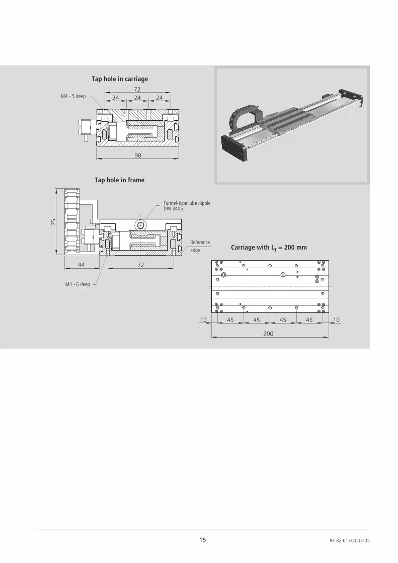
24 24 2472
75
44 72
90
200
10 45 45 45 45 10
Carriage with LT = 200 mm
Tap hole in carriage
Tap hole in frame
M4 - 6 deep
Funnel-type lube nippleDIN 3405
Reference
edge
M4 - 5 deep
RE 82 617/2003-05 16
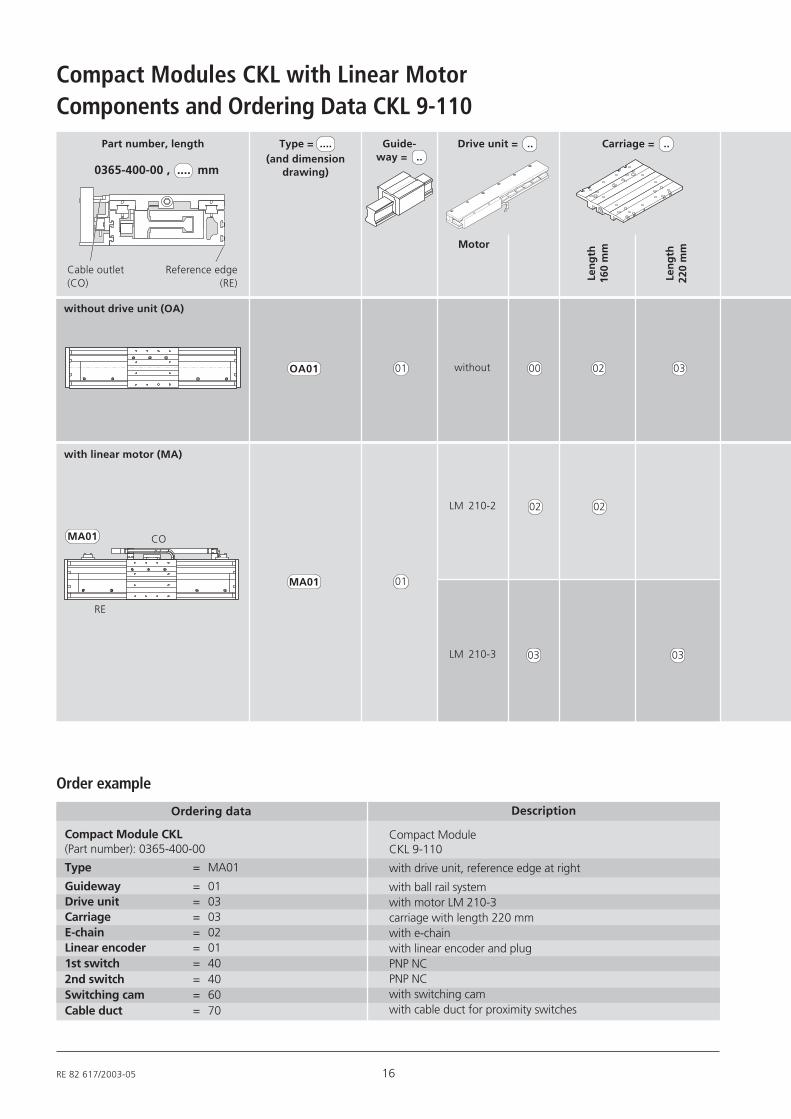
Compact Modules CKL with Linear MotorComponents and Ordering Data CKL 9-110
without drive unit (OA)
Motor
Len
gth
220
mm
OA01
MA01
without
LM 210-2
00
03
03
02
02
with linear motor (MA)
Part number, length
0365-400-00 , .... mm
Type = ....(and dimension
drawing)
Guide-way = ..
Drive unit = .. Carriage = ..
Len
gth
160
mm
01
01
LM 210-3 03
02
Description
Compact ModuleCKL 9-110
with drive unit, reference edge at right
with ball rail systemwith motor LM 210-3carriage with length 220 mmwith e-chainwith linear encoder and plugPNP NCPNP NCwith switching camwith cable duct for proximity switches
Ordering data
Compact Module CKL(Part number): 0365-400-00
Type = MA01
Guideway = 01Drive unit = 03Carriage = 03E-chain = 02Linear encoder = 011st switch = 402nd switch = 40Switching cam = 60Cable duct = 70
Order example
CO
RE
MA01
Cable outlet(CO)
Reference edge(RE)

17 RE 82 617/2003-05
02
05
01
E-chain = .. Linear encoder = .. 1st, 2nd + 3rd switch = .. Documentation = ..
without with e-chain without
Cable duct = ..
00 00
00 02 01
L = (stroke + 2 · excess travel) + LT + 60 mm
Stroke = effective strokeLT = carriage length
If the compact module is to operate re-liably, the excess travel must be greaterthan the braking distance. The brakingdistance can be assumed to be equal tothe acceleration distance. We recommendthat customers mount shock absorbers atthe mass center of gravity to reduce excesstravel.
Calculating the compact modulelength L:
opticalposition sensor
with plug
70with cable duct
60with switching cam
42with PNP NO
40with PNP NC
00without switches Frictionaldrag
Positioningaccuracy
Stan
dar
dre
po
rt
Mea
sure
-m
ent
rep
ort
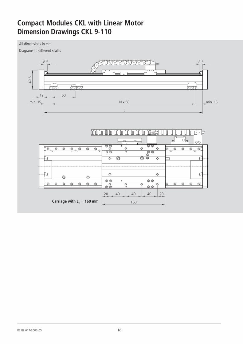
RE 82 617/2003-05 18
Compact Modules CKL with Linear Motor49
.5
12 60
min. 15 min. 15N x 60
L
8.5 8.5
160
20 2040 40 40
Dimension Drawings CKL 9-110
All dimensions in mm
Diagrams to different scales
Carriage with LT = 160 mm

19 RE 82 617/2003-05
90
25 252020
11044
75
50
80
220
25 2542.5 42.5 42.542.5
M5 - 5 deep
Carriage with LT = 220 mm
Tap hole in carriage
Tap hole in frame
M5 - 8 deep
Reference
edge
Funnel-type lube nipple
DIN 3405
RE 82 617/2003-05 20
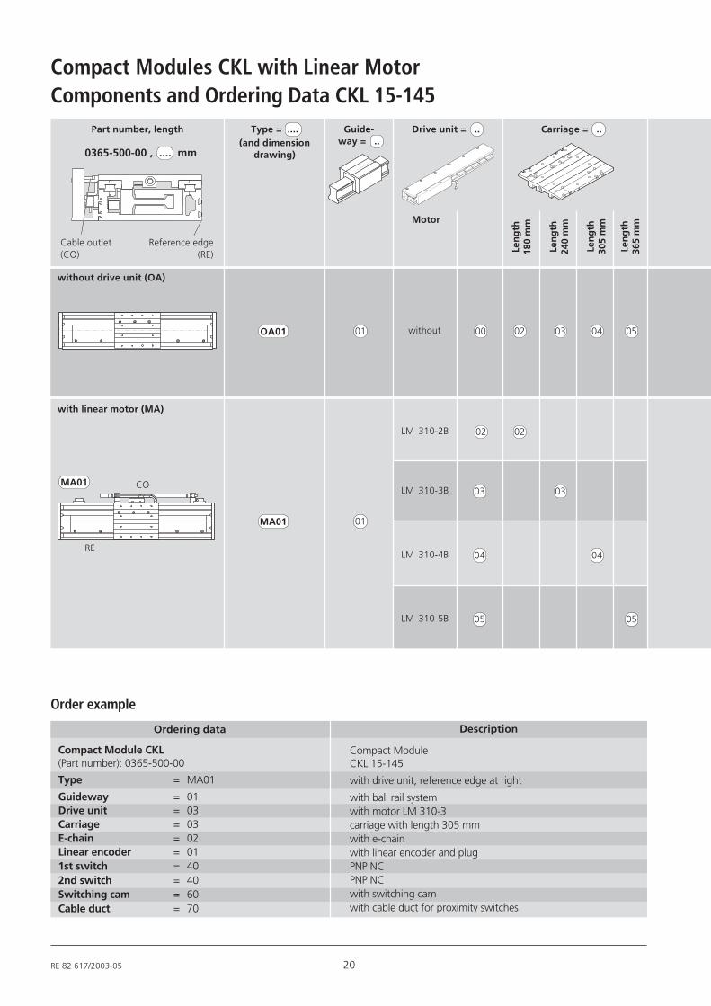
Compact Modules CKL with Linear MotorComponents and Ordering Data CKL 15-145
without drive unit (OA)
Motor
Len
gth
240
mm
Len
gth
305
mm
OA01
MA01
without
LM 310-2B
00
03
03
02
02
with linear motor (MA)
Part number, length
0365-500-00 , .... mm
Type = ....(and dimension
drawing)
Guide-way = ..
Drive unit = .. Carriage = ..
Len
gth
180
mm
01
01
LM 310-3B 03
02
Description
Compact ModuleCKL 15-145
with drive unit, reference edge at right
with ball rail systemwith motor LM 310-3carriage with length 305 mmwith e-chainwith linear encoder and plugPNP NCPNP NCwith switching camwith cable duct for proximity switches
Ordering data
Compact Module CKL(Part number): 0365-500-00
Type = MA01
Guideway = 01Drive unit = 03Carriage = 03E-chain = 02Linear encoder = 011st switch = 402nd switch = 40Switching cam = 60Cable duct = 70
Order example
Len
gth
365
mm
04 05
04LM 310-4B 04
05LM 310-5B 05
CO
RE
MA01
Cable outlet(CO)
Reference edge(RE)

21 RE 82 617/2003-05
02
05
01
E-chain = .. Linear encoder = .. 1st, 2nd + 3rd switch = .. Documentation = ..
without with e-chain without
Cable duct = ..
00 00
00 02 01
L = (stroke + 2 · excess travel) + LT + 60 mm
Stroke = effective strokeLT = carriage length
If the compact module is to operate re-liably, the excess travel must be greaterthan the braking distance. The brakingdistance can be assumed to be equal tothe acceleration distance. We recommendthat customers mount shock absorbers atthe mass center of gravity to reduce excesstravel.
Calculating the compact modulelength L:
70with cable duct
60with switching cam
42with PNP NO
40with PNP NC
00without switches
opticalposition sensor
with plug
Frictionaldrag
Positioningaccuracy
Stan
dar
dre
po
rt
Mea
sure
-m
ent
rep
ort
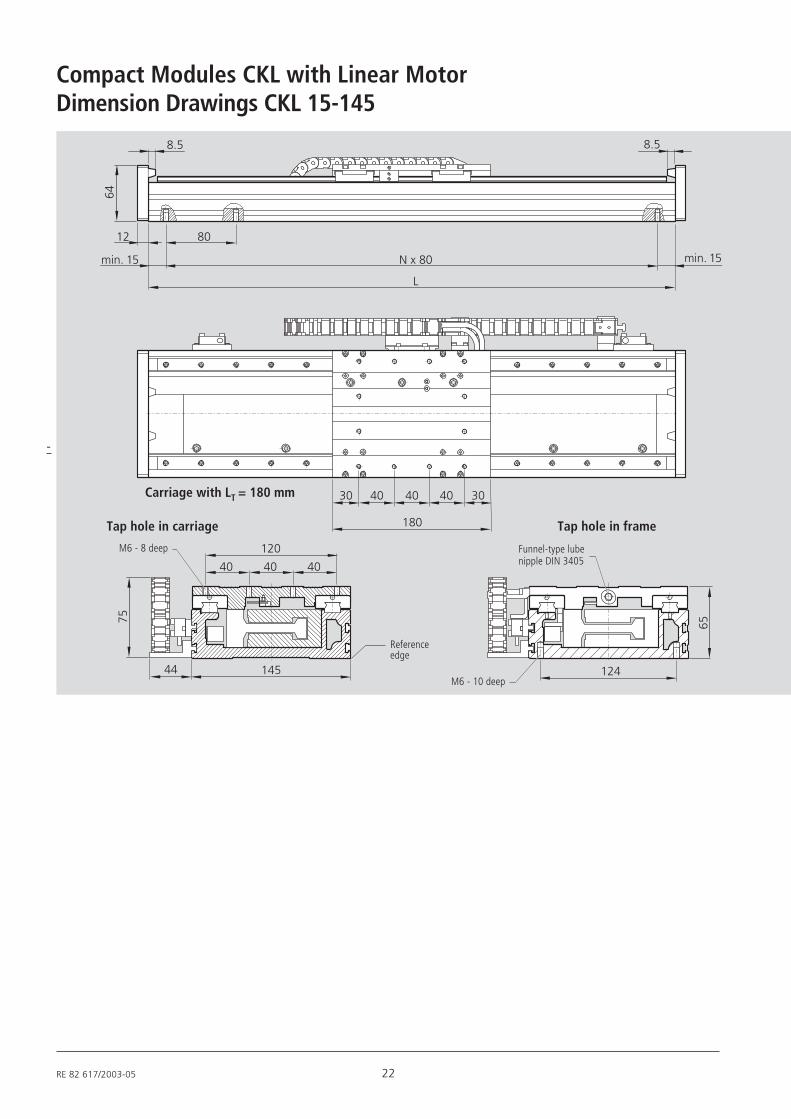
RE 82 617/2003-05 22
Compact Modules CKL with Linear Motor
12 80
min. 15 min. 15N x 80
L
64
8.5 8.5
180
30 3040 40 40
14544
75
40 40 40
120
124
65
Dimension Drawings CKL 15-145
M6 - 10 deep
Carriage with LT = 180 mm
Tap hole in carriage Tap hole in frame
M6 - 8 deep Funnel-type lubenipple DIN 3405
-
Referenceedge
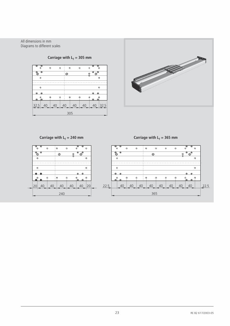
23 RE 82 617/2003-05
20 2040 40 40 40 40
240
32.5 40 40 40 40 40
305
32.540
40 40 40 40 40
365
4022.5 40 40 22.5
All dimensions in mmDiagrams to different scales
Carriage with LT = 305 mm
Carriage with LT = 240 mm Carriage with LT = 365 mm
RE 82 617/2003-05 24
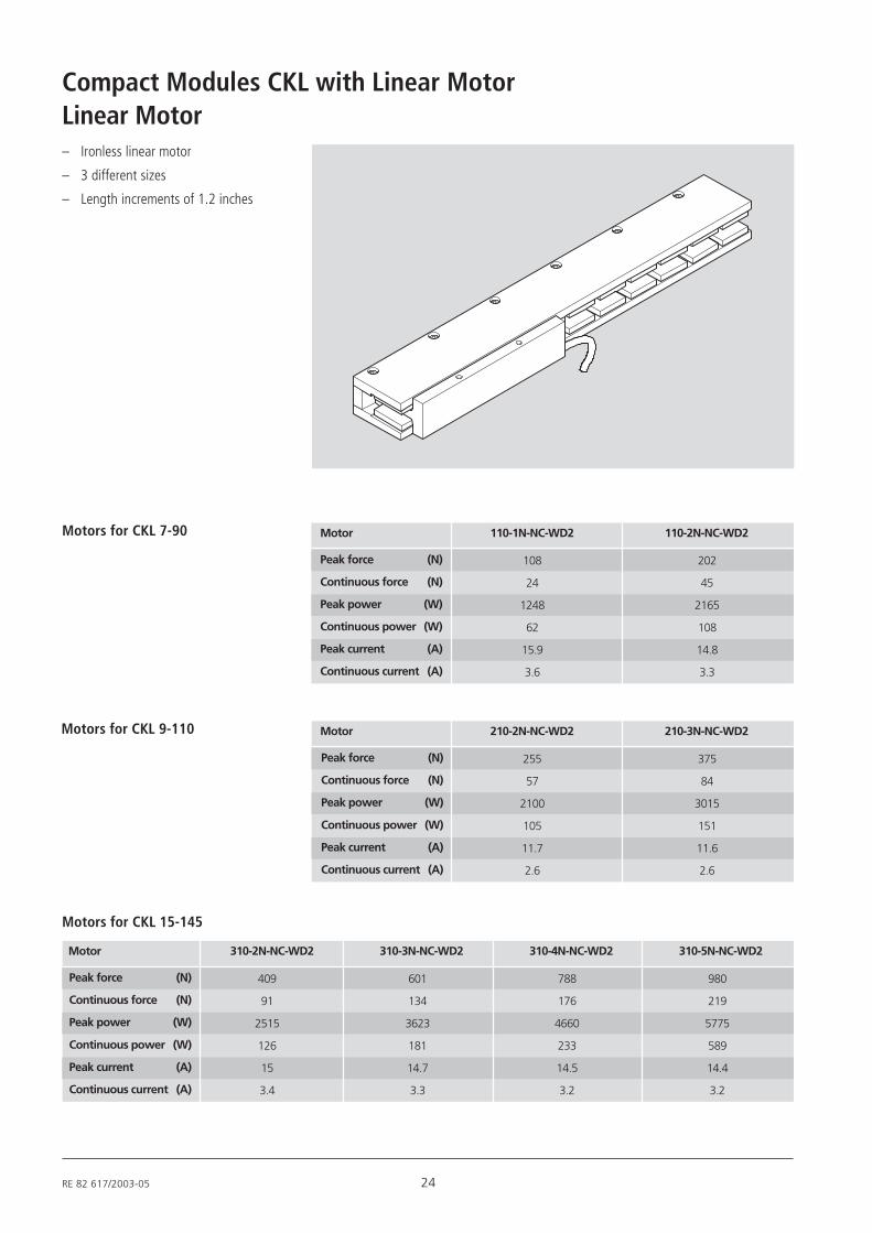
Compact Modules CKL with Linear MotorLinear Motor– Ironless linear motor
– 3 different sizes
– Length increments of 1.2 inches
Motors for CKL 7-90
Motors for CKL 9-110 Motor 210-2N-NC-WD2 210-3N-NC-WD2
255
57
2100
105
11.7
2.6
375
84
3015
151
11.6
2.6
Peak force (N)
Continuous force (N)
Peak power (W)
Continuous power (W)
Peak current (A)
Continuous current (A)
Motor 110-1N-NC-WD2 110-2N-NC-WD2
Peak force (N)
Continuous force (N)
Peak power (W)
Continuous power (W)
Peak current (A)
Continuous current (A)
108
24
1248
62
15.9
3.6
202
45
2165
108
14.8
3.3
Motors for CKL 15-145
Motor 310-2N-NC-WD2 310-3N-NC-WD2 310-4N-NC-WD2 310-5N-NC-WD2
409
91
2515
126
15
3.4
601
134
3623
181
14.7
3.3
Peak force (N)
Continuous force (N)
Peak power (W)
Continuous power (W)
Peak current (A)
Continuous current (A)
788
176
4660
233
14.5
3.2
980
219
5775
589
14.4
3.2
25 RE 82 617/2003-05
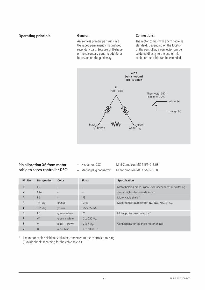
General:
An ironless primary part runs in aU-shaped permanently magnetizedsecondary part. Because of U-shapeof the secondary part, no additionalforces act on the guideway.
Operating principle Connections:
The motor comes with a 5 m cable asstandard. Depending on the locationof the controller, a connector can besoldered directly to the end of thiscable, or the cable can be extended.
– Header on DSC: Mini-Combicon MC 1.5/9-G-5.08
– Mating plug connector: Mini-Combicon MC 1.5/9-ST-5.08
Pin allocation X6 from motorcable to servo controller DSC:
Pin No. Designation Color Signal Specification
BR-
BR+
PE
-MTdig
+MTdig
PE
W
V
U
1
2
3
4
5
6
7
8
9
-
-
PE
GND
+5 V / 5 mA
PE
0 to 230 Veff
0 to 4 Aeff
0 to 1000 Hz
Motor holding brake, signal level independent of switching
status, high-side / low-side switch
Motor cable shield*
Motor temperature sensor, NC, NO, PTC, KTY…
Motor protective conductor*
Connections for the three motor phases
* The motor cable shield must also be connected to the controller housing.(Provide shrink-sheathing for the cable shield.)
WD2Delta woundTHF 10 cable
red
black
Thermostat (NC)opens at 90°C
yellow (+)
orange (–)
blueU
brownV Wgreen
white
-
-
-
orange
yellow
green / yellow
green + white
black + brown
red + blue
RE 82 617/2003-05 26
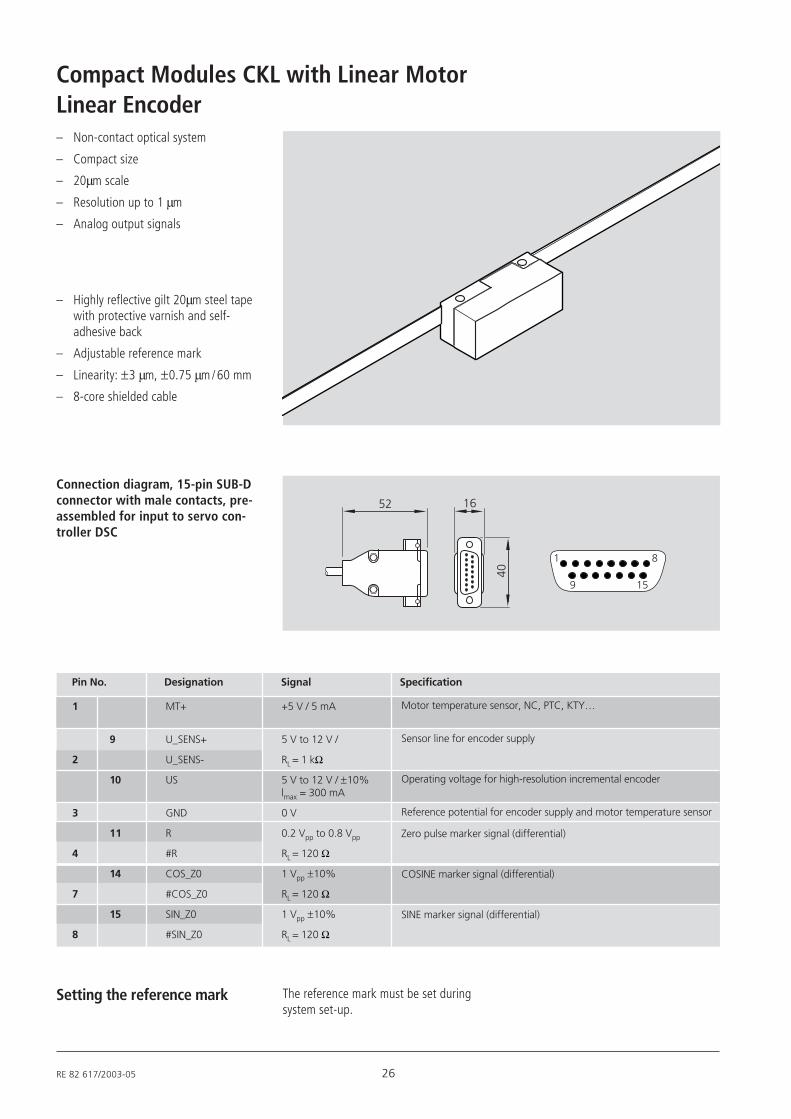
Compact Modules CKL with Linear MotorLinear Encoder– Non-contact optical system
– Compact size
– 20µm scale
– Resolution up to 1 µm
– Analog output signals
– Highly reflective gilt 20µm steel tapewith protective varnish and self-adhesive back
– Adjustable reference mark
– Linearity: ±3 µm, ±0.75 µm / 60 mm
– 8-core shielded cable
Connection diagram, 15-pin SUB-Dconnector with male contacts, pre-assembled for input to servo con-troller DSC
Pin No. Designation Signal Specification
MT+
U_SENS+
U_SENS-
US
GND
R
#R
COS_Z0
#COS_Z0
SIN_Z0
#SIN_Z0
1
9
2
10
3
11
4
14
7
15
8
+5 V / 5 mA
5 V to 12 V /
RL = 1 kΩ
5 V to 12 V / ±10%lmax = 300 mA
0 V
0.2 Vpp to 0.8 Vpp
RL = 120 Ω
1 Vpp ±10%
RL = 120 Ω
1 Vpp ±10%
RL = 120 Ω
Motor temperature sensor, NC, PTC, KTY…
Sensor line for encoder supply
Operating voltage for high-resolution incremental encoder
Reference potential for encoder supply and motor temperature sensor
Zero pulse marker signal (differential)
COSINE marker signal (differential)
SINE marker signal (differential)
The reference mark must be set duringsystem set-up.
Setting the reference mark
27 RE 82 617/2003-05
Electrical specification andtechnical data
Power supply 5 V ±5% 120 mA (typical)150 mA (RGH24Y and RGH24W)
Temperature Storage -20°C to +70°COperating 0°C to +55°C
Humidity 10 - 90% RH non-condensing
Enclosure IP40
Acceleration operating 30 g
Shock (non-operating) 100 g, 11 ms, 1/2 sine
Vibration (operating) 10 g, 55 to 2000 Hz as per IEC 68-2-6
Weight Readhead 11 gCable 34 g/m
EMC compliance EN 50081-2EN 50082-2EN 55011 (cable versions only)
Cable Ø 4.2 mm double shielded cable (standard)Various lengths available on request.Flex life >20 x 106 cycles at min. 20 mm bend radius
Connector options without connector15-pin Sub-D connector as option
Recommended signalconnections
Electrical integration To achieve EMC compliance, the JST connector must becorrectly integrated. In particular, the shielding and ground-ing arrangements are critical. Renishaw recommends the useof a double shielded cable, as described under “Cable”.Refer to the RGH24JST data sheet for electrical connectioninformation.
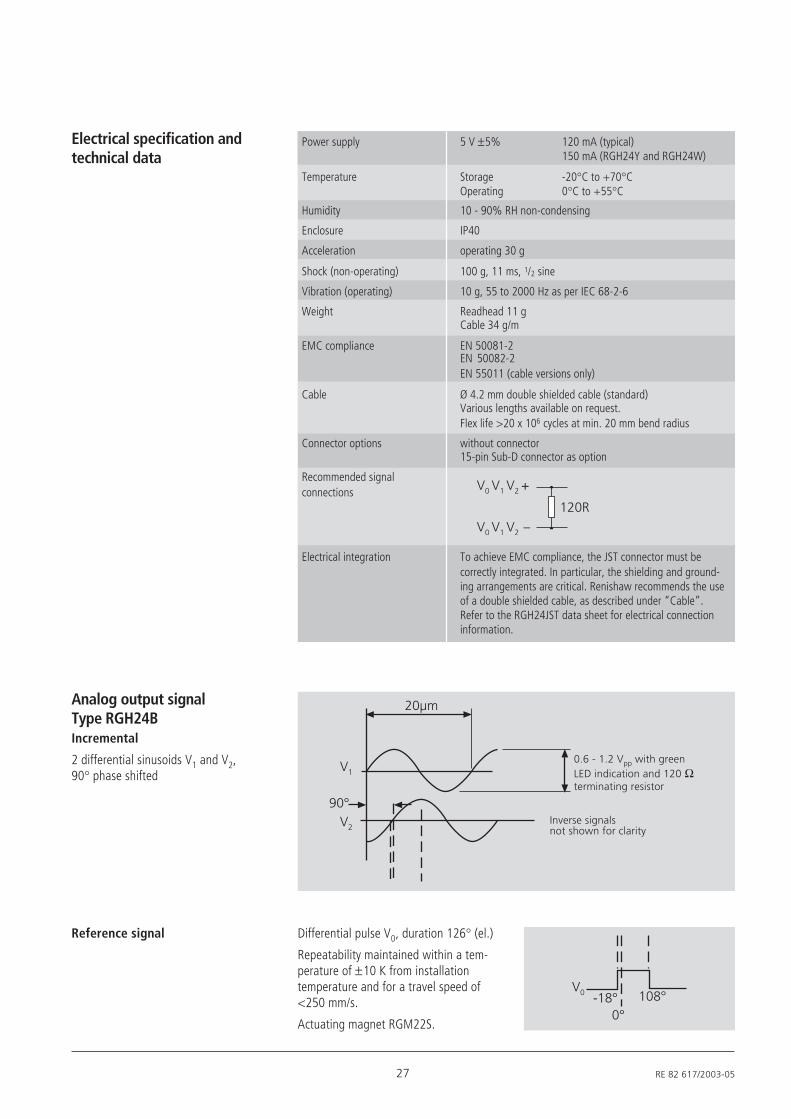
Analog output signalType RGH24BIncremental
2 differential sinusoids V1 and V2,90° phase shifted
Reference signal Differential pulse V0, duration 126° (el.)
Repeatability maintained within a tem-perature of ±10 K from installationtemperature and for a travel speed of<250 mm/s.
Actuating magnet RGM22S.
0.6 - 1.2 Vpp with greenLED indication and 120 Ωterminating resistor
Inverse signalsnot shown for clarity
RE 82 617/2003-05 28
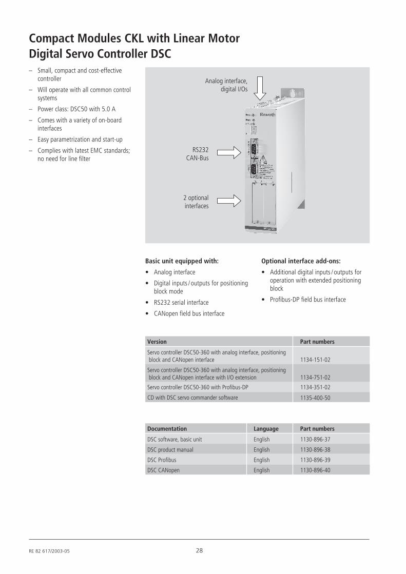
Compact Modules CKL with Linear MotorDigital Servo Controller DSC– Small, compact and cost-effective
controller
– Will operate with all common controlsystems
– Power class: DSC50 with 5.0 A
– Comes with a variety of on-boardinterfaces
– Easy parametrization and start-up
– Complies with latest EMC standards;no need for line filter
Analog interface,digital I/Os
RS232CAN-Bus
2 optionalinterfaces
Basic unit equipped with:
• Analog interface
• Digital inputs / outputs for positioningblock mode
• RS232 serial interface
• CANopen field bus interface
Optional interface add-ons:
• Additional digital inputs / outputs foroperation with extended positioningblock
• Profibus-DP field bus interface
Version Part numbers
Servo controller DSC50-360 with analog interface, positioning block and CANopen interface 1134-151-02
Servo controller DSC50-360 with analog interface, positioning block and CANopen interface with I/O extension 1134-751-02
Servo controller DSC50-360 with Profibus-DP 1134-351-02
CD with DSC servo commander software 1135-400-50
Documentation Language Part numbers
DSC software, basic unit English 1130-896-37
DSC product manual English 1130-896-38
DSC Profibus English 1130-896-39
DSC CANopen English 1130-896-40
29 RE 82 617/2003-05
For start-up, you will require a CD-ROMcontaining:
• the servo commander operating andparametrizing software
• pre-configured parametrizing profilesfor rapid start-up of CKL axes
The CD-ROM and the correspondingmanual can be ordered.
Technical data Before start-up, check that the followingconnections have been made:
• Linear encoder cable to controller
• Motor cable to controller
• Power supply to controller
– Header on DSC: Mini-Combicon MC 1.5/9-G-5.08
– Mating plug connector: Mini-Combicon MC 1.5/9-ST-5.08
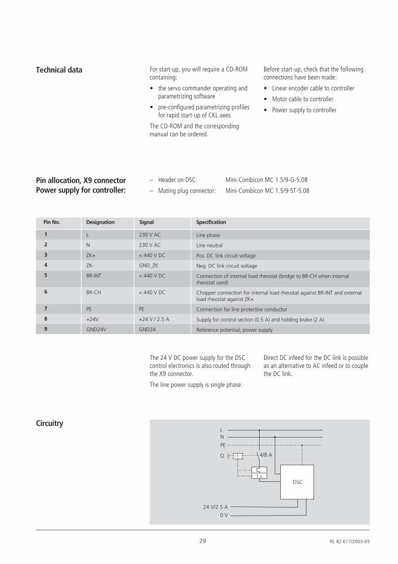
Pin allocation, X9 connectorPower supply for controller:
Pin No. Designation Signal Specification
L
N
ZK+
ZK-
BR-INT
BR-CH
PE
+24V
GND24V
1
2
3
4
5
6
7
8
9
230 V AC
230 V AC
< 440 V DC
GND_ZK
< 440 V DC
< 440 V DC
PE
+24 V / 2.5 A
GND24
Line phase
Line neutral
Pos. DC link circuit voltage
Neg. DC link circuit voltage
Connection of internal load rheostat (bridge to BR-CH when internalrheostat used)
Chopper connection for internal load rheostat against BR-INT and externalload rheostat against ZK+
Connection for line protective conductor
Supply for control section (0.5 A) and holding brake (2 A)
Reference potential, power supply
The 24 V DC power supply for the DSCcontrol electronics is also routed throughthe X9 connector.
The line power supply is single phase.
Direct DC infeed for the DC link is possibleas an alternative to AC infeed or to couplethe DC link.
L
24 V/2.5 A
0 V
N
DSC
PE
I >
4/8 AQ
Circuitry
RE 82 617/2003-05 30
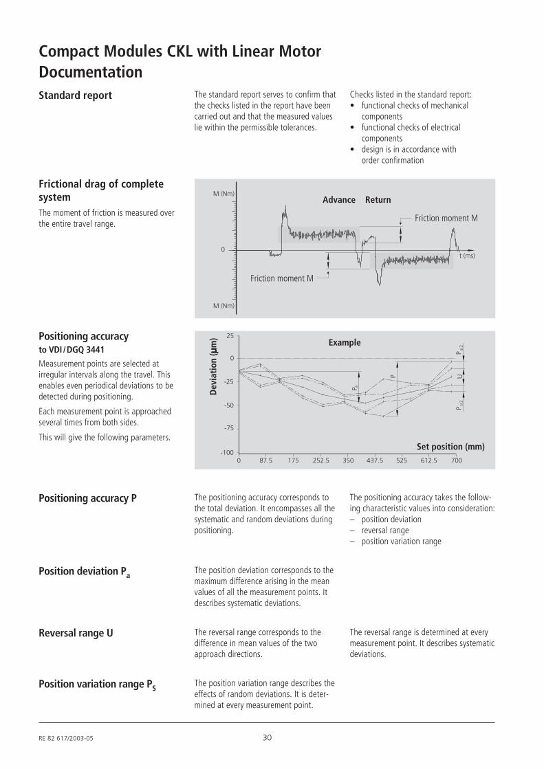
Compact Modules CKL with Linear MotorDocumentationStandard report The standard report serves to confirm that
the checks listed in the report have beencarried out and that the measured valueslie within the permissible tolerances.
Checks listed in the standard report:• functional checks of mechanical
components• functional checks of electrical
components• design is in accordance with
order confirmation
Frictional drag of completesystemThe moment of friction is measured overthe entire travel range.
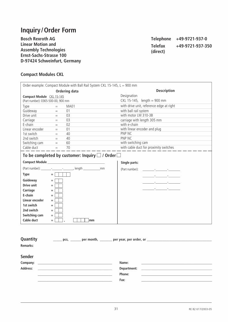
Positioning accuracyto VDI / DGQ 3441
Measurement points are selected atirregular intervals along the travel. Thisenables even periodical deviations to bedetected during positioning.
Each measurement point is approachedseveral times from both sides.
This will give the following parameters.
175 252.5 350 612.5 700
25
0
-25
-50
-75
-1000 87.5 437.5 525
P a
P
Ps/
2P
s/2
U
Advance Return
Friction moment M
Friction moment M
Example
Dev
iati
on ( .... .
m)
Set position (mm)
Reversal range U The reversal range corresponds to thedifference in mean values of the twoapproach directions.
The reversal range is determined at everymeasurement point. It describes systematicdeviations.
Position variation range PSThe position variation range describes theeffects of random deviations. It is deter-mined at every measurement point.
Position deviation PaThe position deviation corresponds to themaximum difference arising in the meanvalues of all the measurement points. Itdescribes systematic deviations.
Positioning accuracy P The positioning accuracy corresponds tothe total deviation. It encompasses all thesystematic and random deviations duringpositioning.
The positioning accuracy takes the follow-ing characteristic values into consideration:– position deviation– reversal range– position variation range
31 RE 82 617/2003-05
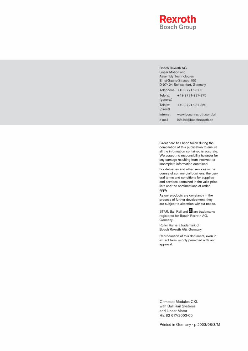
Order example: Compact Module with Ball Rail System CKL 15-145, L = 900 mm
Compact Modules CKL
Ordering data Description
To be completed by customer: Inquiry / OrderCompact Module __________________________________
(Part number): ______-______-______, length __________mm
Type =
Guideway =Drive unit =Carriage =E-chain =Linear encoder =1st switch =2nd switch =Switching cam =Cable duct = , mm
Quantity _____ pcs, ______ per month, _______ per year, per order, or _____________________________________
Remarks:
SenderCompany: ___________________________________________ Name: _________________________________________
Address: ___________________________________________ Department: _________________________________________
___________________________________________ Phone: _________________________________________
___________________________________________ Fax: _________________________________________
Telephone +49-9721-937-0
Telefax +49-9721-937-350(direct)
Compact Module CKL 15-145(Part number): 0365-500-00, 900 mm
Type = MA01Guideway = 01Drive unit = 03Carriage = 03E-chain = 02Linear encoder = 011st switch = 402nd switch = 40Switching cam = 60Cable duct = 70
DesignationCKL 15-145, length = 900 mmwith drive unit, reference edge at rightwith ball rail systemwith motor LM 310-3Bcarriage with length 305 mmwith e-chainwith linear encoder and plugPNP NCPNP NCwith switching camwith cable duct for proximity switches
Single parts:
(Part number): _______-_______-_______
_______-_______-_______
_______-_______-_______
_______-_______-_______
Inquiry / Order FormBosch Rexroth AGLinear Motion andAssembly TechnologiesErnst-Sachs-Strasse 100D-97424 Schweinfurt, Germany
Bosch Rexroth AGLinear Motion andAssembly TechnologiesErnst-Sachs-Strasse 100D-97424 Schweinfurt, Germany
Telephone +49-9721-937-0
Telefax +49-9721-937-275(general)
Telefax +49-9721-937-350(direct)
Internet www.boschrexroth.com/brl
e-mail [email protected]
Great care has been taken during thecompilation of this publication to ensureall the information contained is accurate.We accept no responsibility however forany damage resulting from incorrect orincomplete information contained.
For deliveries and other services in thecourse of commercial business, the gen-eral terms and conditions for suppliesand services contained in the valid pricelists and the confirmations of orderapply.
As our products are constantly in theprocess of further development, theyare subject to alteration without notice.
STAR, Ball Rail and are trademarksregistered for Bosch Rexroth AG,Germany.
Roller Rail is a trademark ofBosch Rexroth AG, Germany.
Reproduction of this document, even inextract form, is only permitted with ourapproval.
Compact Modules CKLwith Ball Rail Systemsand Linear MotorRE 82 617/2003-05
Printed in Germany - p 2003/08/3/M


![Mini Ball Rail[1]](https://img.pdfslide.us/doc/110x75/541b10f67bef0ae1168b4764/mini-ball-rail1.jpg)