Embed Size (px)
Citation preview
WIT FOR POST-INSTALLED REBAR
Benefi ts:• Europ
28
POST -INSTALLED REBAR
The guideline specifi es a number of tests in order to qualify products for post-installed rebar applications. These are the performance areas checked by the tests:1. Bond strength in diff erent strengths of concrete.2. Substandard hole cleaning.3. Wet concrete.4. Sustained load and temperature infl uence.5. Freeze-thaw conditions.6. Installation directions.7. Maximum embedment depth.8. Avoidance of air bubbles during injection.9. Durability (corrosion, chemical attack).
If an adhesive meets all assessment criteria, rebar connections carried out with this adhesive can be designed with the bond strength and minimum anchorage length according to EN 1992-1-1as given in the tables below for diff erent Würth injection adhesives.Adhesives (or in conjunction with a certain drilling procedure) which do not fully comply with all assessment criteria can still obtain an approval.• If the bond strength obtained in tests does not fulfi l the specifi ed requirements, then bond strengths lower than those given by EN 1992-1-1 shall be applied. These values are given in the respective approval.
Rebar used as Anchor versus Post-installed Rebar Connections
Tab. 1: Comparison of potential failure modes.
Rebar used as AnchorSituations where the concrete needs to take up tensile load from the anchorage or where reinforcing bars are designed to carry shear loads should be considered as “rebar used as anchors” and designed according to anchor design method such as given e.g. in the guidelines of EOTA and ACI or simplifi ed in this Design Manual. Those guidelines verify all possible failure loads in tension and shear.
Post-installed Rebar ConnectionThe design of the rebar anchorage is performed according to structural concrete design codes, e.g. EN 1992-1-1 or ACI 318. With a given test regime
and a subsequent assessment (EOTA-Technical Report TR 023) it is proven that the load transfer for post-installed reinforcing bars is similar to cast in bars if the stiff ness of the overall load transfer mechanism is similar to the cast-in system. The effi ciency depends on the strength of the adhesive mortar against the concentrated load close to the ribs and on the capacity of load transfer at the interface of the drilled hole.In many cases the bond values of post-installed bars are higher compared to cast in bars due to better performance of the adhesive mortar. But for small edge distance and/or narrow spacing, splitting or spalling forces become decisive due to the low tensile capacity of the concrete.
Rebar used as Anchor Post-installed Rebar Connection
Failure modes in tension Failure modes in shear Failure modes in tension Failure modes in shear
Steel failure of fastener Steel failure of fastener without lever arm
Steel failure of reinforcing bar
Steel failure of fastener with lever arm
Bond failure
Pull-out failure of fastener Concrete pry-out failure Splitting failure
Combined pull-out and concrete failure
Concrete edge failure
Concrete cone failure
Splitting failure
Post-installed rebar anchorage – The assessment criteria of EOTA-Technical Report TR 023
29
POST
-INS
TALL
ED R
EBAR
• If it cannot be shown that the bond strength of reinforcing bars post-installed with a selected product and cast-in reinforcing bars in cracked concrete (w=0.3mm) is similar, then the minimum anchorage length lb,min and the minimum overlap length l0,min shall be increased by a factor 1.5.
Applications
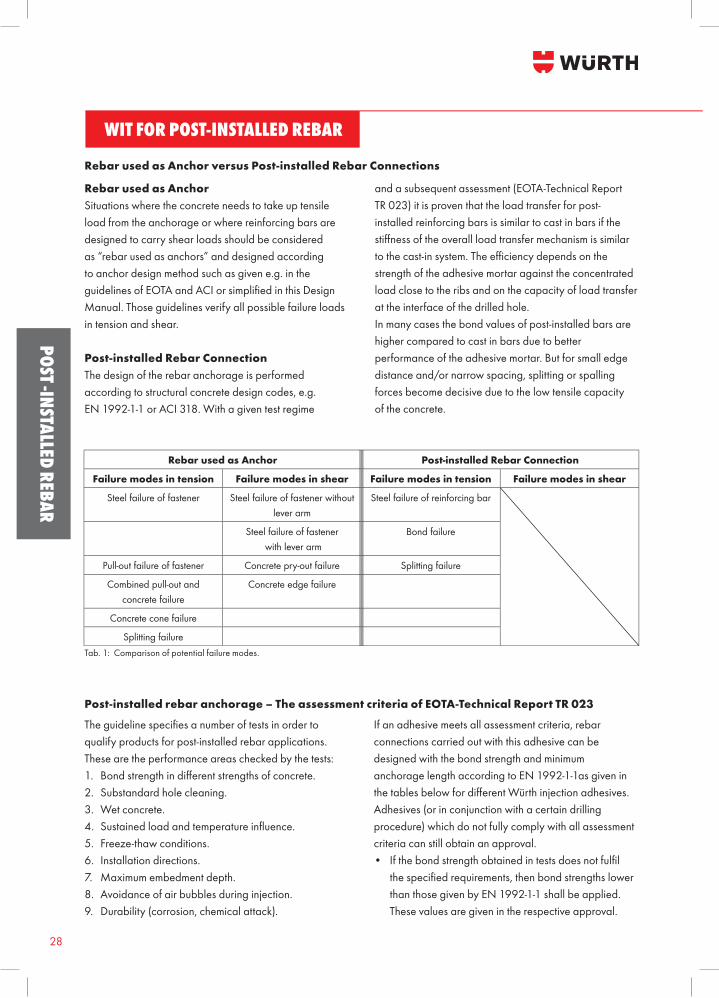
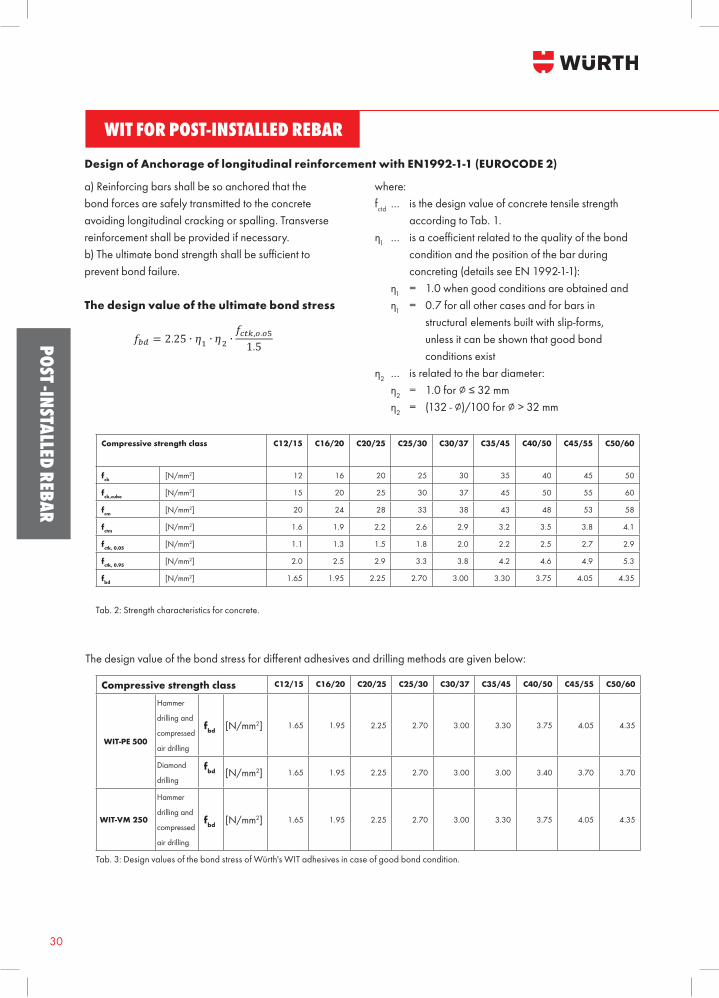
Products tested according to above guideline can be used for applications in non-carbonated concrete C12/15 to C50/60 (EN 206) only, which are also allowed with straight deformed cast-in bars according to (EC2), e.g. those in the following applications: Note to the following Figures: In the Figures no transverse reinforcement is plotted, the transverse reinforcement as required by EC 2 shall be present. The shear transfer between old and new concrete shall be designed according to EC 2.
Fig. 1: Overlap joint for rebar connections.
Fig. 2: End anchoring of slabs or beams.
Fig. 3: Overlap joint at a foundation of a column or wall where the
rebars are stressed in tension.
Fig. 4: Rebar connection for components stressed primarily in
compression. The rebars are stressed in compression.
Fig. 5: Anchoring of reinforcement to cover.
Design Manual 2 (18) JoB-130605-001
WIT fo r po s t - in s ta lled r ebar
If an adhesive meets all assessment criteria, rebar connections carried out with this adhesive can be designed with the bond strength and minimum anchorage length according to EN 1992-1-1as given in the tables below for different Würth injection adhesives. Adhesives (or in conjunction with a certain drilling procedure) which do not fully comply with all assessment criteria can still obtain an approval.
If the bond strength obtained in tests does not fulfil the specified requirements, then bond strengths lower than those
given by EN 1992-1-1 shall be applied. These values are given in the respective approval. If it cannot be shown that the bond strength of reinforcing bars post-installed with a selected product and cast-in
reinforcing bars in cracked concrete (w=0.3mm) is similar, then the minimum anchorage length lb,min and the minimum overlap length l0,min shall be increased by a factor 1.5.
Applications Products tested according to above guideline can be used for applications in non-carbonated concrete C12/15 to C50/60
(EN 206) only, which are also allowed with straight deformed cast-in bars according to (EC2), e.g. those in the following applications: Note to the following Figures: In the Figures no transverse reinforcement is plotted, the transverse reinforcement as required by EC 2 shall be present. The shear transfer between old and new concrete shall be designed according to EC 2.
Fig. 1: Overlap joint for rebar connections
Fig. 2: End anchoring of slabs or beams,
Design Manual 3 (18) JoB-130605-001
WIT fo r po s t - in s ta lled r ebar
Fig. 3: Overlap joint at a foundation of a column or wall where the rebars are stressed in tension
Fig. 4: Rebar connection for components stressed primarily in compression. The rebars are stressed in compression
Fig. 5: Anchoring of reinforcement to cover
Anwendungsbilder
WIT FOR POST-INSTALLED REBAR
Benefits:• Europ
30
POST -INSTALLED REBAR
a) Reinforcing bars shall be so anchored that the bond forces are safely transmitted to the concrete avoiding longitudinal cracking or spalling. Transverse reinforcement shall be provided if necessary.b) The ultimate bond strength shall be sufficient to prevent bond failure.
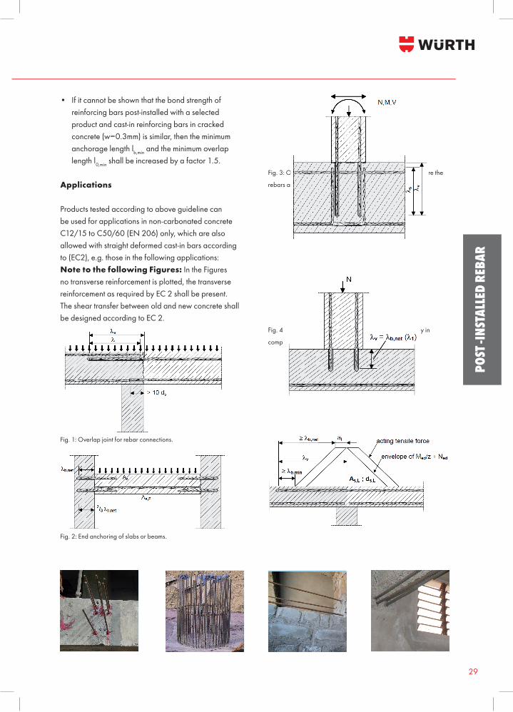
The design value of the ultimate bond stress
where:fctd … is the design value of concrete tensile strength according to Tab. 1.η1 … is a coefficient related to the quality of the bond condition and the position of the bar during concreting (details see EN 1992-1-1): η1 = 1.0 when good conditions are obtained and η1 = 0.7 for all other cases and for bars in structural elements built with slip-forms, unless it can be shown that good bond conditions existη2 … is related to the bar diameter: η2 = 1.0 for ∅ ≤ 32 mm η2 = (132 - ∅)/100 for ∅ > 32 mm
Design of Anchorage of longitudinal reinforcement with EN1992-1-1 (EUROCODE 2)
Compressive strength class C12/15 C16/20 C20/25 C25/30 C30/37 C35/45 C40/50 C45/55 C50/60
fck [N/mm2] 12 16 20 25 30 35 40 45 50
fck,cube [N/mm2] 15 20 25 30 37 45 50 55 60
fcm [N/mm2] 20 24 28 33 38 43 48 53 58
fctm [N/mm2] 1.6 1.9 2.2 2.6 2.9 3.2 3.5 3.8 4.1
fctk, 0.05 [N/mm2] 1.1 1.3 1.5 1.8 2.0 2.2 2.5 2.7 2.9
fctk, 0.95 [N/mm2] 2.0 2.5 2.9 3.3 3.8 4.2 4.6 4.9 5.3
fbd [N/mm2] 1.65 1.95 2.25 2.70 3.00 3.30 3.75 4.05 4.35
Tab. 2: Strength characteristics for concrete.
The design value of the bond stress for different adhesives and drilling methods are given below:
Compressive strength class C12/15 C16/20 C20/25 C25/30 C30/37 C35/45 C40/50 C45/55 C50/60
WIT-PE 500
Hammer
drilling and
compressed
air drilling
fbd [N/mm2] 1.65 1.95 2.25 2.70 3.00 3.30 3.75 4.05 4.35
Diamond
drilling
fbd [N/mm2] 1.65 1.95 2.25 2.70 3.00 3.00 3.40 3.70 3.70
WIT-VM 250
Hammer
drilling and
compressed
air drilling
fbd [N/mm2] 1.65 1.95 2.25 2.70 3.00 3.30 3.75 4.05 4.35
Tab. 3: Design values of the bond stress of Würth's WIT adhesives in case of good bond condition.
31
POST
-INS
TALL
ED R
EBAR
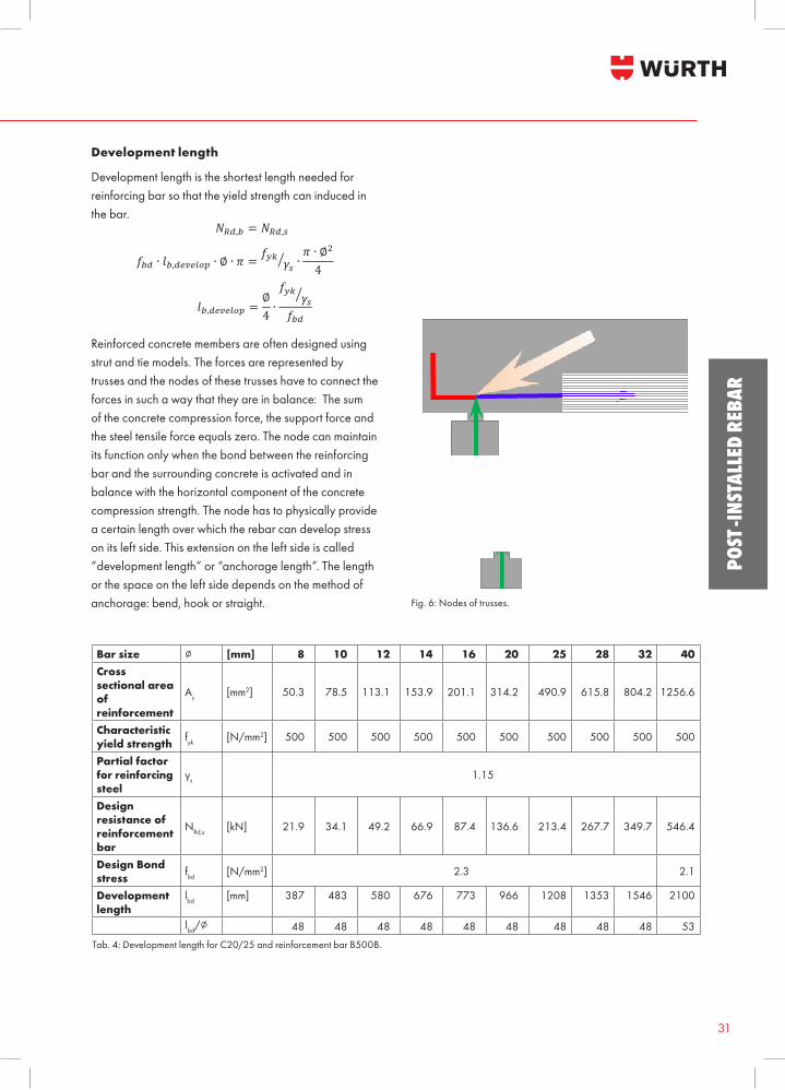
Development length is the shortest length needed for reinforcing bar so that the yield strength can induced in the bar.
Reinforced concrete members are often designed using strut and tie models. The forces are represented by trusses and the nodes of these trusses have to connect the forces in such a way that they are in balance: The sum of the concrete compression force, the support force and the steel tensile force equals zero. The node can maintain its function only when the bond between the reinforcing bar and the surrounding concrete is activated and in balance with the horizontal component of the concrete compression strength. The node has to physically provide a certain length over which the rebar can develop stress on its left side. This extension on the left side is called “development length” or “anchorage length”. The length or the space on the left side depends on the method of anchorage: bend, hook or straight.
Development length
Fig. 6: Nodes of trusses.
Bar size ∅ [mm] 8 10 12 14 16 20 25 28 32 40Cross sectional area of reinforcement
As [mm2] 50.3 78.5 113.1 153.9 201.1 314.2 490.9 615.8 804.2 1256.6
Characteristic yield strength fyk [N/mm2] 500 500 500 500 500 500 500 500 500 500
Partial factor for reinforcing steel
γs 1.15
Design resistance of reinforcement bar
NRd,s [kN] 21.9 34.1 49.2 66.9 87.4 136.6 213.4 267.7 349.7 546.4
Design Bond stress fbd [N/mm2] 2.3 2.1
Development length
lbd [mm] 387 483 580 676 773 966 1208 1353 1546 2100
lbd/∅ 48 48 48 48 48 48 48 48 48 53Tab. 4: Development length for C20/25 and reinforcement bar B500B.
WIT FOR POST-INSTALLED REBAR
Benefi ts:• Europ
32
POST -INSTALLED REBAR
Bar
size
Cross sectional areaof reinforcement
Characteristic yield strength of reinforcement B500B
Partial factor for reinforcing steelDesign restistance of reinforcement bar
Design Bond stress
Development length
Minimum anchorage length
Des
ign
load
for
good
bon
d co
nditi
on, C
20/2
5
∅A s
f ykγ s
NRd
,sf bd
l bdl b,
min
Nb,
d
[mm
][m
m2 ]
[N/m
m2 ][k
N]
[N/m
m2 ][m
m]
[kN
]
850
.350
01.
1521
.92.
338
611
67
78
811
1417
20
1078
.550
01.
1534
.12.
348
314
511
1418
2125
28
1211
3.1
500
1.15
49.2
2.3
580
174
1721
2530
3442
1415
3.9
500
1.15
66.9
2.3
676
203
2530
3540
4959
1620
1.1
500
1.15
87.4
2.3
773
232
2834
4045
5768
79
2031
4.2
500
1.15
136.
62.
396
629
042
4957
7185
9911
312
7
2549
0.9
500
1.15
213.
42.
312
0836
271
8810
612
414
115
917
719
421
2
2861
5.8
500
1.15
267.
72.
313
5340
699
119
139
158
178
198
218
238
257
3280
4.2
500
1.15
349.
72.
315
4646
411
313
615
818
120
422
624
927
129
431
733
9
4012
56.6
500
1.15
546.
42.
121
0063
018
220
823
426
028
631
233
836
439
041
644
246
849
452
054
6
Anch
orag
e le
ngth
[mm
]12
013
014
015
020
025
030
035
040
050
060
070
080
090
010
0011
0012
0013
0014
0015
0016
0017
0018
0019
0020
0021
00
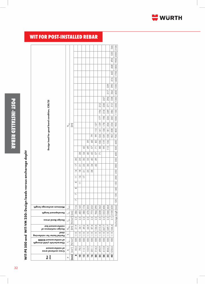
WIT
-PE
500
and
WIT
-VM
250
: Des
ign
load
s ve
rsus
anc
hora
ge d
epht
33
POST
-INS
TALL
ED R
EBAR
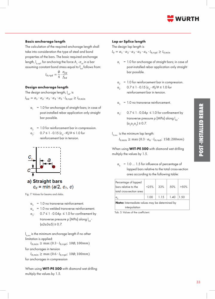
Basic anchorage length The calculation of the required anchorage length shall take into consideration the type of steel and bond properties of the bars. The basic required anchorage length, lb,rqd, for anchoring the force As ■ σsd in a bar assuming constant bond stress equal to fbd follows from:
Design anchorage lengthThe design anchorage length, lbd, is
α1 = 1.0 for anchorage of straight bars; in case of post-installed rebar application only straight bar possible. α2 = 1.0 for reinforcement bar in compression. α2: 0.7 ≤ 1 - 0.15 (cd - ∅)/∅ ≤ 1.0 for reinforcement bar in tension.
Fig. 7: Values for beams and slabs.
α3 = 1.0 no transverse reinforcement. α4 = 1.0 no welded transverse reinforcement. α5: 0.7 ≤ 1 - 0.04ρ ≤ 1.0 for confi nement by transverse pressure ρ [MPa] along lbd ■ (α2α3α5) ≥ 0.7.
lb,min is the minimum anchorage length if no other limitation is applied: for anchorages in tension
for anchorages in compression
When using WIT-PE 500 with diamond wet drilling multiply the values by 1.5.
Lap or Splice length The design lap length is
α1 = 1.0 for anchorage of straight bars; in case of post-installed rebar application only straight bar possible. α2 = 1.0 for reinforcement bar in compression. α2 0.7 ≤ 1 - 0.15 (cd - ∅)/∅ ≤ 1.0 for reinforcement bar in tension.
α3 = 1.0 no transverse reinforcement.
α5: 0.7 ≤ 1 - 0.04ρ ≤ 1.0 for confi nement by transverse pressure ρ [MPa] along lbd ■ (α2α3α5) ≥ 0.7.
l0,min is the minimum lap length:
When using WIT-PE 500 with diamond wet drilling multiply the values by 1.5.
α6 = 1.0 … 1.5 for infl uence of percentage of lapped bars relative to the total cross-section area according to the following table:
Tab. 5: Values of the coeffi cient.
Design Manual 9 (18) JoB-130605-001
WIT fo r po s t - in s ta lled r ebar
Basic anchorage length The calculation of the required anchorage length shall take into consideration the type of steel and bond properties of the bars. The basic required anchorage length, lb,rqd, for anchoring the force As.σsd in a bar assuming constant bond stress equal to fbd follows from:
!!,!"# =∅4∙!!"!!"
Design anchorage length The design anchorage length, lbd, is !!" = !! ∙ !! ∙ !! ∙ !! ∙ !! ∙ !!,!"# ≥ !!,!"#
α1 = 1.0 for anchorage of straight bars; in case of post-installed rebar application only straight bar possible.
α2 = 1.0 for reinforcement bar in compression. α2: 0.7 ≤ 1 - 0.15 (cd - ∅)/∅ ≤ 1.0 for reinforcement bar in tension.
Fig. 7: Values for beams and slabs
α3 = 1.0 no transverse reinfordement.
α4 = 1.0 no welded transverse reinforcement. α5: 0.7 ≤ 1 - 0.04ρ ≤ 1.0 for confinement by transverse pressure ρ [MPa] along lbd . (α2α3α5) ≥ 0.7. lb,min is the minimum anchorage length if no other limitation is applied:
!!,!"# ≥ max (0.3 ∙ !!,!"#; 10∅; 100!!) for anchorages in tension
!!,!"# ≥ max (0.6 ∙ !!,!"#; 10∅; 100!!) for anchorages in compression
When using WIT-PE 500 with diamond wet drilling multiply the values by 1.5. Lap or Splice length The design lap length is !! = !! ∙ !! ∙ !! ∙ !! ∙ !! ∙ !!,!"# ≥ !!,!"#
Percentage of lapped bars relative to the total cross-section area
<25% 33% 50% >50%
a6 1.00 1.15 1.40 1.50
Note: Intermediate values may be determined by interpolation
WIT FOR POST-INSTALLED REBAR
Benefits:• Europ
34
POST -INSTALLED REBAR
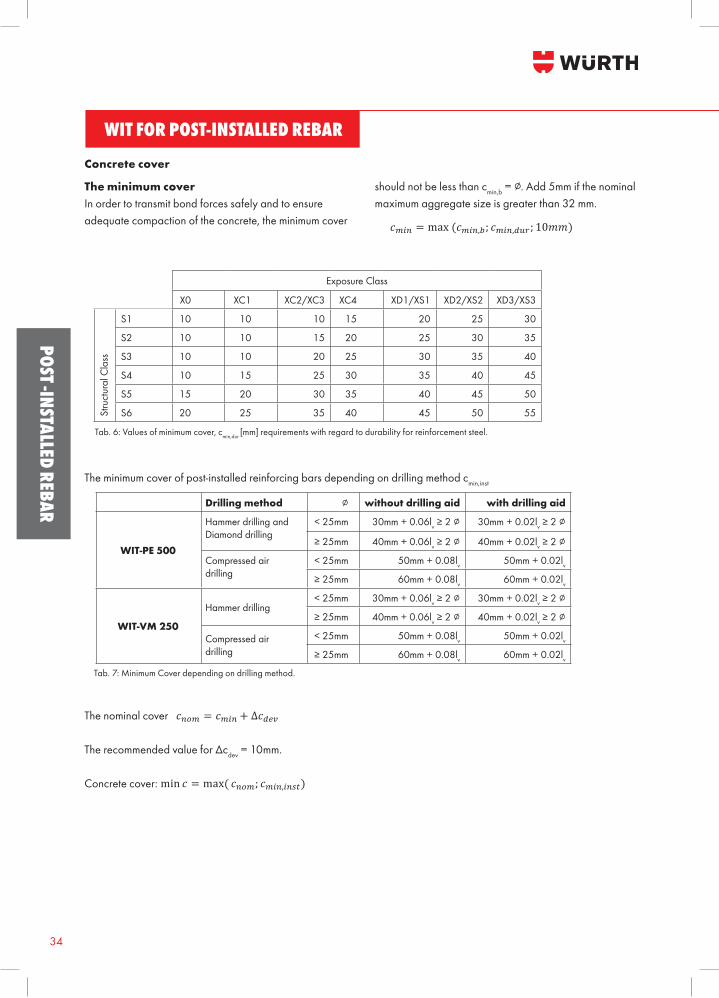
The minimum coverIn order to transmit bond forces safely and to ensure adequate compaction of the concrete, the minimum cover
should not be less than cmin,b = ∅. Add 5mm if the nominal maximum aggregate size is greater than 32 mm.
Concrete cover
Tab. 6: Values of minimum cover, cmin,dur [mm] requirements with regard to durability for reinforcement steel.
The minimum cover of post-installed reinforcing bars depending on drilling method cmin,inst
Drilling method ∅ without drilling aid with drilling aid
WIT-PE 500
Hammer drilling andDiamond drilling
< 25mm 30mm + 0.06lv ≥ 2 ∅ 30mm + 0.02lv ≥ 2 ∅
≥ 25mm 40mm + 0.06lv ≥ 2 ∅ 40mm + 0.02lv ≥ 2 ∅
Compressed airdrilling
< 25mm 50mm + 0.08lv 50mm + 0.02lv≥ 25mm 60mm + 0.08lv 60mm + 0.02lv
WIT-VM 250
Hammer drilling< 25mm 30mm + 0.06lv ≥ 2 ∅ 30mm + 0.02lv ≥ 2 ∅
≥ 25mm 40mm + 0.06lv ≥ 2 ∅ 40mm + 0.02lv ≥ 2 ∅
Compressed airdrilling
< 25mm 50mm + 0.08lv 50mm + 0.02lv≥ 25mm 60mm + 0.08lv 60mm + 0.02lv
Exposure Class
X0 XC1 XC2/XC3 XC4 XD1/XS1 XD2/XS2 XD3/XS3
Stru
ctur
al C
lass
S1 10 10 10 15 20 25 30
S2 10 10 15 20 25 30 35
S3 10 10 20 25 30 35 40
S4 10 15 25 30 35 40 45
S5 15 20 30 35 40 45 50
S6 20 25 35 40 45 50 55
Tab. 7: Minimum Cover depending on drilling method.
The nominal cover
The recommended value for Δcdev = 10mm.
Concrete cover:
35
POST
-INS
TALL
ED R
EBAR
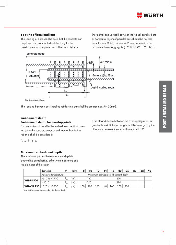
Spacing of bars and lapsThe spacing of bars shall be such that the concrete can be placed and compacted satisfactorily for the development of adequate bond. The clear distance
(horizontal and vertical) between individual parallel bars or horizontal layers of parallel bars should be not less than the max(∅; (dg + 5 mm) or 20mm) where dg is the maximum size of aggregate (8.2; EN1992-1-1:2011-01).
Design Manual 11 (18) JoB-130605-001
WIT fo r po s t - in s ta lled r ebar
WIT-VM 250
Hammer drilling < 25mm 30mm + 0.06 lv ≥ 2∅ 30mm + 0.02 lv ≥ 2∅
≥ 25mm 40mm + 0.06 lv ≥ 2∅ 40mm + 0.02 lv ≥ 2∅
Compressed air drilling
< 25mm 50mm + 0.08 lv 50mm + 0.02 lv
≥ 25mm 60mm + 0.08 lv 60mm + 0.02 lv Tab. 7: Minimum Cover depending on drilling method
The nominal cover !!"# = !!"# + ∆!!"#
The recommended value for ∆cdev = 10mm. Concrete cover: min ! = max( !!"#; !!"#,!"#$) Spacing of bars and laps The spacing of bars shall be such that the concrete can be placed and compacted satisfactorily for the development of
adequate bond. The clear distance (horizontal and vertical) between individual parallel bars or horizontal layers of parallel bars should be not less than the max(∅; (dg + 5 mm) or 20mm) where dg is the maximum size of aggregate (8.2; EN1992-1-
1:2011-01 .
Fig. 8: Adjacent laps
The spacing between post-installed reinforcing bars shall be greater max(5∅; 50mm), Embedment depth Embedment depth for overlap joints For calculation of the effective embedment depth of overlap joints the concrete cover at end-face of bonded-in rebar c1 shall be considered: !! ≥ !! + !! If the clear distance between the overlapping rebar is greater than 4 Ø the lap length shall be enlarged by the difference between the clear distance and 4 Ø.
Fig. 8: Adjacent laps.
The spacing between post-installed reinforcing bars shall be greater max(5∅; 50mm).
Embedment depthEmbedment depth for overlap jointsFor calculation of the eff ective embedment depth of over-lap joints the concrete cover at end-face of bonded-in rebar c1 shall be considered:
If the clear distance between the overlapping rebar is greater than 4 Ø the lap length shall be enlarged by the diff erence between the clear distance and 4 Ø.
Maximum embedment depth The maximum permissible embedment depth is depending on adhesive, adhesive temperature and the diameter of the rebar:
Bar size ∅ [mm] 8 10 12 14 16 20 25 28 32 40Adhesive temperature Maximum permissible embedment depth
WIT-PE 500+5°C to +19°C lmax [cm] 130 200≥ 20°C lmax [cm] 200 280
WIT-VM 250 +5°C to +25°C lmax [cm] 100 100 120 140 160 200 200Tab. 8: Maximum approved embedment depth.
WIT FOR POST-INSTALLED REBAR
Benefi ts:• Europ
36
POST -INSTALLED REBAR
Transverse reinforcementThe requirements of transverse reinforcement in the area of the post-installed rebar connection shall comply with EN 1992-1-1, Section 8.7.4.
Connection jointThe transfer of shear forces between new concrete and existing structure shall be designed according to EN 1992-1-1, Section 6.2.5 “Shear at the interface between concrete cast at diff erent times”.The joints for concreting must be roughened to at least such an extent that aggregate protrude. In case of a carbonated surface of the existing concrete structure the carbonated layer shall be removed in the area of the post-installed rebar connection with a diameter of (Ø + 60mm) prior to the installation of the new rebar. The depth of concrete to be removed shall correspond to at least the minimum concrete cover for the respective environmental conditions in accordance with EN 1992-1-1. The foregoing may be neglected if building components are new and not carbonated and if building components are in dry conditions.
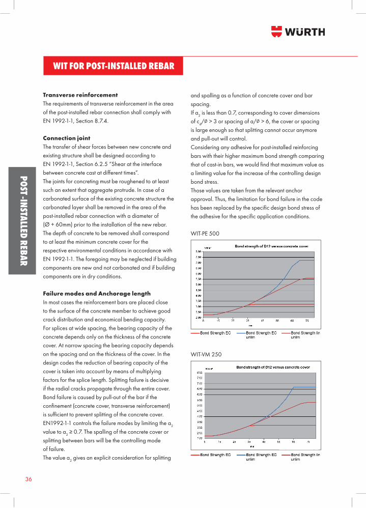
Failure modes and Anchorage lengthIn most cases the reinforcement bars are placed close to the surface of the concrete member to achieve good crack distribution and economical bending capacity. For splices at wide spacing, the bearing capacity of the concrete depends only on the thickness of the concrete cover. At narrow spacing the bearing capacity depends on the spacing and on the thickness of the cover. In the design codes the reduction of bearing capacity of the cover is taken into account by means of multiplying factors for the splice length. Splitting failure is decisive if the radial cracks propagate through the entire cover. Bond failure is caused by pull-out of the bar if the confi nement (concrete cover, transverse reinforcement) is suffi cient to prevent splitting of the concrete cover. EN1992-1-1 controls the failure modes by limiting the α2 value to α2 ≥ 0.7. The spalling of the concrete cover or splitting between bars will be the controlling mode of failure. The value α2 gives an explicit consideration for splitting
and spalling as a function of concrete cover and bar spacing.If α2 is less than 0.7, corresponding to cover dimensions of cd/∅ > 3 or spacing of a/∅ > 6, the cover or spacing is large enough so that splitting cannot occur anymore and pull-out will control. Considering any adhesive for post-installed reinforcing bars with their higher maximum bond strength comparing that of cast-in bars, we would fi nd that maximum value as a limiting value for the increase of the controlling design bond stress. Those values are taken from the relevant anchor approval. Thus, the limitation for bond failure in the code has been replaced by the specifi c design bond stress of the adhesive for the specifi c application conditions.
WIT-PE 500
WIT-VM 250
Design Manual 13 (18) JoB-130605-001
WIT fo r po s t - in s ta lled r ebar
For the modification of the design for a particular adhesives with its specific design bond strength, the value α2 was adapted
in such a way to create a linear extension of the bond strength function exceeding cd/∅ > 3 or spacing of a/∅ > 6 and calibrated on the basis of tests with the additional limit of a lowest adapted α2 of 0.25. The design values exceeding cd/∅ > 3 or spacing of a/∅ > 6
Bar size ∅ [mm] 8 10 12 14 16 20 25 28 32 40
Service temperature Maximum design bond strength
WIT-PE 500 ≤ +24°C fbd,ext [N/mm2] 6.0 6.0 5.6 5.6 5.3 4.7 4.4 4.4 4.4 3.4
WIT-VM 250 fbd,ext [N/mm2] 5.3 5.3 5.3 5.3 5.3 5.3 5.3 4.9 4.6 -
37
POST
-INS
TALL
ED R
EBAR
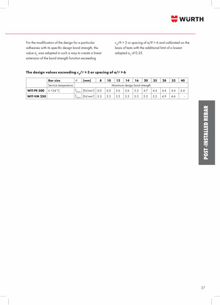
For the modifi cation of the design for a particular adhesives with its specifi c design bond strength, the value α2 was adapted in such a way to create a linear extension of the bond strength function exceeding
cd/∅ > 3 or spacing of a/∅ > 6 and calibrated on the basis of tests with the additional limit of a lowest adapted α2 of 0.25.
The design values exceeding cd/∅ > 3 or spacing of a/∅ > 6
Bar size ∅ [mm] 8 10 12 14 16 20 25 28 32 40Service temperature Maximum design bond strength
WIT-PE 500 ≤ +24°C fbd,ext [N/mm2] 6.0 6.0 5.6 5.6 5.3 4.7 4.4 4.4 4.4 3.4
WIT-VM 250 fbd,ext [N/mm2] 5.3 5.3 5.3 5.3 5.3 5.3 5.3 4.9 4.6 -
WIT FOR POST-INSTALLED REBAR
Benefits:• Europ
38
POST -INSTALLED REBAR
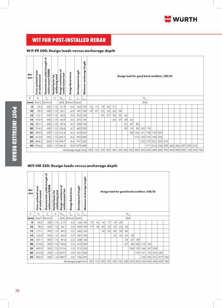
W IT-PE 500: Design loads versus anchorage depth
Barsize
Cros
s se
ctio
nal a
rea
of r
einf
orce
men
t
Char
acte
rist
ic y
ield
str
engt
h of
re
info
rcem
ent B
500B
Part
ial f
acto
r fo
r r
einf
orci
ng s
teel
Des
ign
rest
ista
nce
of
rein
forc
emen
t bar
Des
ign
Bond
str
ess
Dev
elop
men
t len
gth
Min
imum
anc
hora
ge le
ngth
Design load for good bond condition, C20/25
∅ As fykγs NRd,s fbd lbd lb,min Nb,d
[mm] [mm2] [N/mm2] [kN] [N/mm2] [mm] [kN]
8 50.3 500 1.15 21.9 6.0 145 100 15 17 18 20 21
10 78.5 500 1.15 34.1 6.0 181 100 19 21 23 25 26 28
12 113.1 500 1.15 49.2 5.6 233 120 25 27 30 32 42
14 153.9 500 1.15 66.9 5.6 272 140 34 37 49 62
16 201.1 500 1.15 87.4 5.3 328 160 53 67 80
20 314.2 500 1.15 136.6 4.7 463 200 59 74 89 103 118
25 490.9 500 1.15 213.4 4.4 618 250 86 104 121 138 173 207
28 615.8 500 1.15 267.7 4.4 692 280 116 135 155 194 232
32 804.2 500 1.15 349.7 4.4 791 320 155 177 221 265 310
40 1256.6 500 1.15 546.4 3.4 1279 400 171 214 256 299 342 385 427 470 513
Anchorage length [mm] 100 110 120 130 140 150 200 250 300 350 400 500 600 700 800 900 1000 1100 1200 1300
WIT-VM 250: Design loads versus anchorage depth
Barsize
Cros
s se
ctio
nal a
rea
of r
einf
orce
men
t
Char
acte
rist
ic y
ield
str
engt
h of
re
info
rcem
ent B
500B
Part
ial f
acto
r fo
r r
einf
orci
ng s
teel
Des
ign
rest
ista
nce
of
rein
forc
emen
t bar
Des
ign
Bond
str
ess
Dev
elop
men
t len
gth
Min
imum
anc
hora
ge le
ngth
Design load for good bond condition, C20/25
∅ As fykγs NRd,s fbd lbd lb,min Nb,d
[mm] [mm2] [N/mm2] [kN] [N/mm2] [mm] [kN]
8 50.3 500 1.15 21.9 5.3 164 100 13 15 16 17 19 20
10 78.5 500 1.15 34.1 5.3 205 100 17 18 20 22 23 25 33
12 113.1 500 1.15 49.2 5.3 246 120 24 26 28 30 40
14 153.9 500 1.15 66.9 5.3 287 140 33 35 47 58
16 201.1 500 1.15 87.4 5.3 328 160 53 67 80
20 314.2 500 1.15 136.6 5.3 410 200 67 83 100 117 133
25 490.9 500 1.15 213.4 5.3 513 250 104 125 146 167 208
28 615.8 500 1.15 267.7 4.9 621 280 129 151 172 216 259
32 804.2 500 1.15 349.7 4.6 756 320 162 185 231 277 324
Anchorage length [mm] 100 110 120 130 140 150 200 250 300 350 400 500 600 700
39
POST
-INS
TALL
ED R
EBAR
Barsize
Cros
s se
ctio
nal a
rea
of r
einf
orce
men
t
Char
acte
rist
ic y
ield
str
engt
h of
re
info
rcem
ent B
500B
Part
ial f
acto
r fo
r r
einf
orci
ng s
teel
Des
ign
rest
ista
nce
of
rein
forc
emen
t bar
Des
ign
Bond
str
ess
Dev
elop
men
t len
gth
Min
imum
anc
hora
ge le
ngth
Design load for good bond condition, C20/25
∅ As fykγs NRd,s fbd lbd lb,min Nb,d
[mm] [mm2] [N/mm2] [kN] [N/mm2] [mm] [kN]
8 50.3 500 1.15 21.9 6.0 145 100 15 17 18 20 21
10 78.5 500 1.15 34.1 6.0 181 100 19 21 23 25 26 28
12 113.1 500 1.15 49.2 5.6 233 120 25 27 30 32 42
14 153.9 500 1.15 66.9 5.6 272 140 34 37 49 62
16 201.1 500 1.15 87.4 5.3 328 160 53 67 80
20 314.2 500 1.15 136.6 4.7 463 200 59 74 89 103 118
25 490.9 500 1.15 213.4 4.4 618 250 86 104 121 138 173 207
28 615.8 500 1.15 267.7 4.4 692 280 116 135 155 194 232
32 804.2 500 1.15 349.7 4.4 791 320 155 177 221 265 310
40 1256.6 500 1.15 546.4 3.4 1279 400 171 214 256 299 342 385 427 470 513
Anchorage length [mm] 100 110 120 130 140 150 200 250 300 350 400 500 600 700 800 900 1000 1100 1200 1300
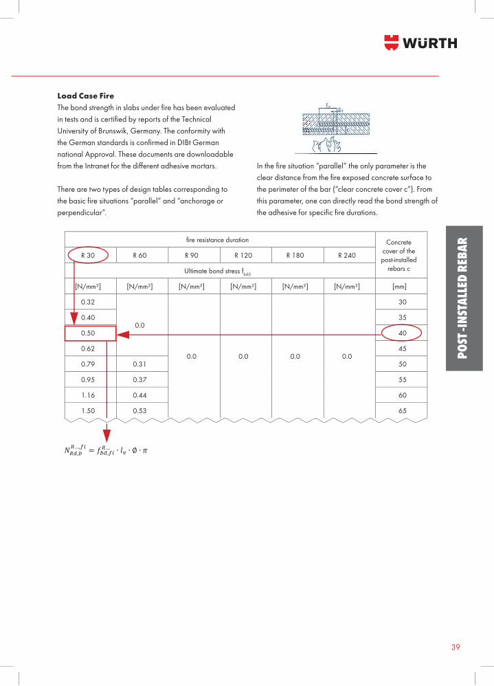
Load Case FireThe bond strength in slabs under fi re has been evaluated in tests and is certifi ed by reports of the Technical University of Brunswik, Germany. The conformity with the German standards is confi rmed in DIBt German national Approval. These documents are downloadable from the Intranet for the diff erent adhesive mortars.
There are two types of design tables corresponding to the basic fi re situations “parallel” and “anchorage or perpendicular”.
In the fi re situation “parallel” the only parameter is the clear distance from the fi re exposed concrete surface to the perimeter of the bar (“clear concrete cover c”). From this parameter, one can directly read the bond strength of the adhesive for specifi c fi re durations.
Design Manual 15 (18) JoB-130605-001
WIT fo r po s t - in s ta lled r ebar
Load C ase Fire The bond strength in slabs under fire has been evaluated in tests and is certified by reports of the Technical University of
Brunswik, Germany. The conformity with the German standards is confirmed in DIBt German national Approval. These documents are downloadable from the Intranet for the different adhesive mortars. There are two types of design tables corresponding to the basic fire situations “parallel” and “anchorage or perpendicular”.
In the fire situation “parallel” the only parameter is the clear distance from the fire exposed concrete surface to the perimeter of the bar (“clear concrete cover c”). From this parameter, one can directly read the bond strength of the adhesive for specific fire durations.
!!",!!…,!" = !!",!"!… ∙ !! ∙ ∅ ∙ !
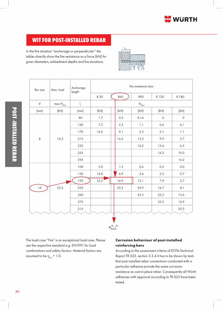
In the fire situation “anchorage or perpendicular” the tables directly show the fire resistance as a force [kN] for given diameters, embedment depths and fire durations.
Da müssen wir was englisches draus machen. Strater hat bestimmt die Urtabellen
fi re resistance duration Concrete cover of the post-installed
rebars c
R 30 R 60 R 90 R 120 R 180 R 240
Ultimate bond stress fbd,fi
[N/mm²] [N/mm²] [N/mm²] [N/mm²] [N/mm²] [N/mm²] [mm]
0.32
0.0
0.0 0.0 0.0 0.0
30
0.40 35
0.50 40
0.62 45
0.79 0.31 50
0.95 0.37 55
1.16 0.44 60
1.50 0.53 65
WIT FOR POST-INSTALLED REBAR
Benefi ts:• Europ
40
POST -INSTALLED REBAR
Bar size Max. load Anchorage lenght
fi re resistance class
R 30 R60 R90 R 120 R 180
∅ max NRd,fi lv NRd,fi
[mm] [kN] [mm] [kN] [kN] [kN] [kN] [kN]
8 16.2
80 1.7 0.5 0.14 0 0
120 7.5 2.3 1.1 0.6 0.1
170 16.2 9.1 5.3 3.1 1.1
215 16.2 13.2 9.9 3.7
235 16.2 13.4 6.5
255 16.2 10.0
295 16.2
10 25.3
100 5.0 1.5 0.6 0.2 0.0
150 16.0 6.9 3.6 2.2 0.7
195 25.3 16.9 12.1 7.9 2.7
235 25.3 20.9 16.7 8.1
260 25.3 22.2 13.6
275 25.3 16.9
315 25.3
The load case “Fire” is an exceptional load case. Please see the respective standard e.g. EN1991 for load combinations and safety factors. Material factors are assumed to be γM,fi = 1.0.
Corrosion behaviour of post-installed reinforcing barsAccording to the assessment criteria of EOTA-Technical Report TR 023, section 3.3.4 it has to be shown by tests that post installed rebar connections conducted with a particular adhesive provide the same corrosion resistance as cast-in-place rebar. Consequently all Würth adhesives with approval according to TR 023 have been tested.
In the fi re situation “anchorage or perpendicular” the tables directly show the fi re resistance as a force [kN] for given diameters, embedment depths and fi re durations.
Design Manual 15 (18) JoB-130605-001
WIT fo r po s t - in s ta lled r ebar
Load C ase Fire The bond strength in slabs under fire has been evaluated in tests and is certified by reports of the Technical University of
Brunswik, Germany. The conformity with the German standards is confirmed in DIBt German national Approval. These documents are downloadable from the Intranet for the different adhesive mortars. There are two types of design tables corresponding to the basic fire situations “parallel” and “anchorage or perpendicular”.
In the fire situation “parallel” the only parameter is the clear distance from the fire exposed concrete surface to the perimeter of the bar (“clear concrete cover c”). From this parameter, one can directly read the bond strength of the adhesive for specific fire durations.
!!",!!…,!" = !!",!"!… ∙ !! ∙ ∅ ∙ !
In the fire situation “anchorage or perpendicular” the tables directly show the fire resistance as a force [kN] for given diameters, embedment depths and fire durations.
Da müssen wir was englisches draus machen. Strater hat bestimmt die Urtabellen
41
POST
-INS
TALL
ED R
EBAR
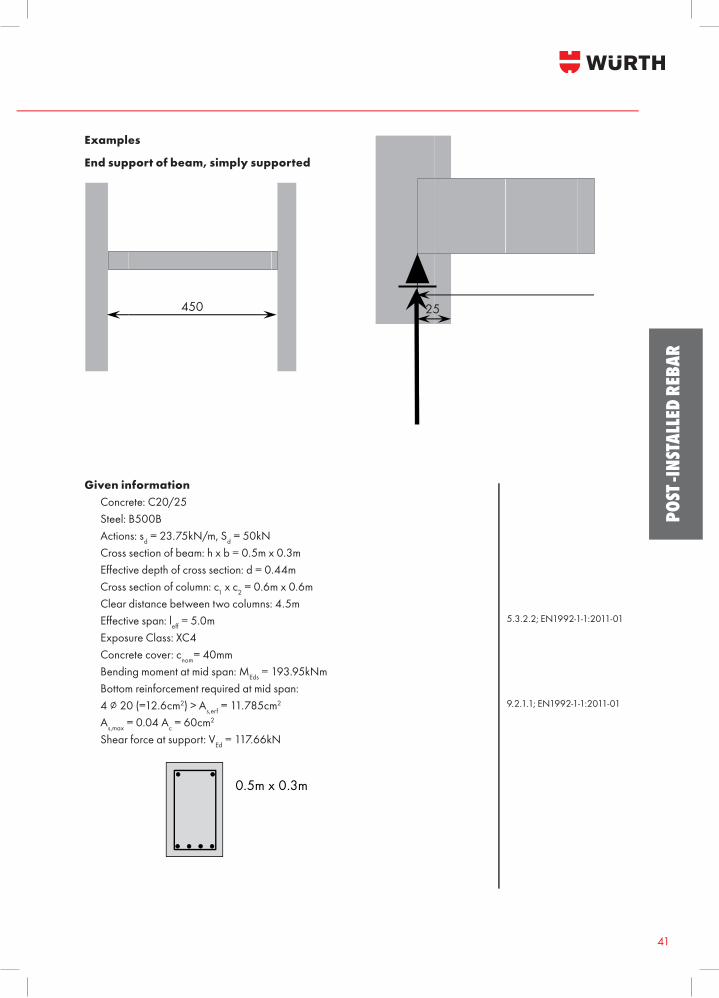
End support of beam, simply supported
Given information Concrete: C20/25 Steel: B500B Actions: sd = 23.75kN/m, Sd = 50kN Cross section of beam: h x b = 0.5m x 0.3m Eff ective depth of cross section: d = 0.44m Cross section of column: c1 x c2 = 0.6m x 0.6m Clear distance between two columns: 4.5m Eff ective span: leff = 5.0m Exposure Class: XC4 Concrete cover: cnom= 40mm Bending moment at mid span: MEds = 193.95kNm Bottom reinforcement required at mid span: 4 ∅ 20 (=12.6cm2) > As,erf = 11.785cm2
As,max = 0.04 Ac = 60cm2
Shear force at support: VEd = 117.66kN
Examples
5.3.2.2; EN1992-1-1:2011-01
9.2.1.1; EN1992-1-1:2011-01
Design Manual 17 (18) JoB-130605-001
WIT fo r po s t - in s ta lled r ebar
Examples End support of beam, simply supported
Given information Concrete: C20/25 Steel: B500B Actions: sd = 23.75kN/m, Sd = 50kN Cross section of beam: h x b = 0.5m x 0.3m Effective depth of cross section: d = 0.44m Cross section of column: c1 x c2 = 0.6m x 0.6m Clear distance between two columns: 4.5m Effective span: leff = 5.0m 5.3.2.2; EN1992-1-1:2011-01 Exposure Class: XC4 Concrete cover: cnom= 40mm Bending moment at mid span: MEds = 193.95kNm
Bottom reinforcement required at mid span: 4 ∅ 20 (=12.6cm2) > As,erf = 11.785cm2
As,max = 0.04 Ac = 60cm2 9.2.1.1; EN1992-1-1:2011-01 Shear force at support: VEd = 117.66kN
Bottom reinforcement at Support
Tensile force to be anchored: !! = !!" ∙ !!!
9.2.1.4 (2); EN1992-1-1:2011-01
! = 0.9 ∙ ! = 0.9 ∙ 0.44 = 0.396 6.2.3 (1); EN1992-1-1:2011-01
!! =! cot ! − cot!
2
9.2.1.3 (2); EN1992-1-1:2011-01 6.2.3 (1); EN1992-1-1:2011-01
!! = ! 9.2.1.3 (2); EN1992-1-1:2011-01
!! = !!" ∙!!!=117.660.9
= 130.73!"
450
25
500
VEd = 117.66kN
0.5m x 0.3m
De
E E G
B
esign Manual
WIT for p
xamples
End support of
Given informatConcretSteel: BActions:Cross seEffectiveCross seClear dEffectiveExposurConcretBendingBottom 4 ∅ 20As,max = 0Shear fo
ottom reinforcTensile
post-installe
f beam, simply
tion te: C20/25 500B : sd = 23.75kection of beae depth of croection of coluistance betwee span: leff = 5re Class: XC4te cover: cnom=g moment at mreinforcemen (=12.6cm2) >0.04 Ac = 60corce at suppo
cement at Supforce to be a
450
ed rebar ap
ly supported
N/m, Sd = 50m: h x b = 0.oss section: dumn: c1 x c2 = een two colum
5.0m 4 = 40mm mid span: ME
nt required at > As,erf = 11.7cm2 ort: VEd = 117
pport nchored:
0
0.5m
17
pplication
0kN 5m x 0.3m = 0.44m 0.6m x 0.6mmns: 4.5m
ds = 193.95kN mid span: 85cm2
7.66kN
m x 0.3m
7 (18)
m
Nm
25
VEd
5.3
9.2
9.2
6.29.26.29.2
5
5
= 117.66kN
.2.2; EN1992
.1.1; EN1992
.1.4 (2); EN19
.3 (1); EN199
.1.3 (2); EN19
.3 (1); EN199
.1.3 (2); EN19
500
N
JoB-130
-1-1:2011-01
-1-1:2011-01
992-1-1:2011-
92-1-1:2011-0992-1-1:2011-92-1-1:2011-0992-1-1:2011-
0605-001
-01
1 -01 1 -01
WIT FOR POST-INSTALLED REBAR
Benefi ts:• Europ
42
POST -INSTALLED REBAR
Bottom reinforcement at SupportTensile force to be anchored:
Steel section required:
Minimum reinforcement at support:
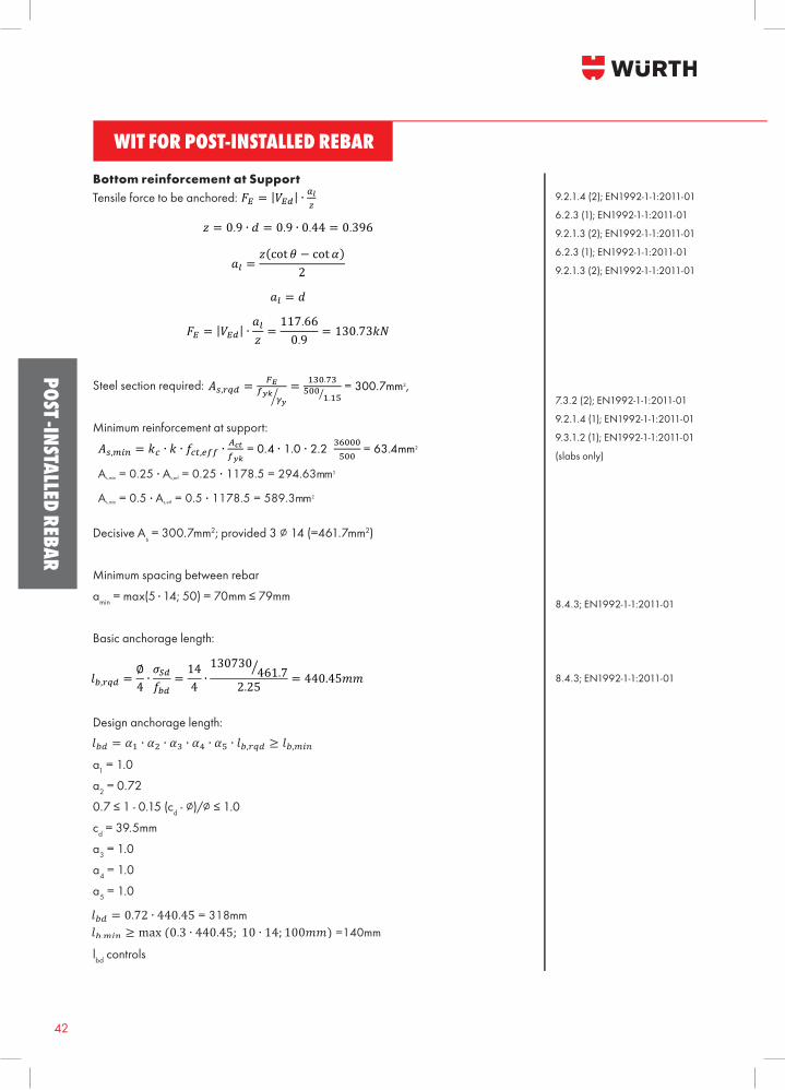
Decisive As = 300.7mm2; provided 3 ∅ 14 (=461.7mm2)
Minimum spacing between rebar
amin = max(5 ■ 14; 50) = 70mm ≤ 79mm
Basic anchorage length:
Design anchorage length:
α1 = 1.0
α2 = 0.72
0.7 ≤ 1 - 0.15 (cd - ∅)/∅ ≤ 1.0
cd = 39.5mm
α3 = 1.0
α4 = 1.0
α5 = 1.0
lbd controls
9.2.1.4 (2); EN1992-1-1:2011-01
6.2.3 (1); EN1992-1-1:2011-01
9.2.1.3 (2); EN1992-1-1:2011-01
6.2.3 (1); EN1992-1-1:2011-01
9.2.1.3 (2); EN1992-1-1:2011-01
7.3.2 (2); EN1992-1-1:2011-01
9.2.1.4 (1); EN1992-1-1:2011-01
9.3.1.2 (1); EN1992-1-1:2011-01
(slabs only)
8.4.3; EN1992-1-1:2011-01
8.4.3; EN1992-1-1:2011-01
43
POST
-INS
TALL
ED R
EBAR
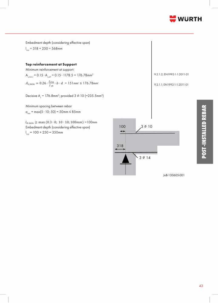
Top reinforcement at SupportMinimum reinforcement at support:As,min,t = 0.15 ■ As,erf = 0.15 ■ 1178.5 = 176.78mm2
Decisive As = 176.8mm2; provided 3 ∅ 10 (=235.5mm2)
Minimum spacing between rebar amin = max(5 ■ 10; 50) = 50mm ≤ 85mm
Embedment depth (considering eff ective span)linst = 100 + 250 = 350mm
9.2.1.2; EN1992-1-1:2011-01
9.2.1.1; EN1992-1-1:2011-01
Design Manual 18 (18) JoB-130605-001
WIT fo r po s t - in s ta lled r ebar
Steel section required: !!,!"# =!!
!!"!!= !"#.!"
!""!.!"
= 300.7mm2,
Minimum reinforcement at support:
!!,!"# = !! ∙ ! ∙ !!",!"" ∙!!"!!"
= 0.4 ∙ 1.0 ∙ 2.2 ∙ !"###!""
= 63.4mm2 7.3.2 (2); EN1992-1-1:2011-01
As,min = 0.25 . As,erf = 0.25 . 1178.5 = 294.63mm2 9.2.1.4 (1); EN1992-1-1:2011-01
As,min = 0.5 . As,erf = 0.5 . 1178.5 = 589.3mm2 9.3.1.2 (1); EN1992-1-1:2011-01 (slabs only)
Decisive As = 300.7mm2; provided 3 ∅ 14 (=461.7mm2) Minimum spacing between rebar amin = max(5 . 14; 50) = 70mm ≤ 79mm Basic anchorage length: 8.4.3; EN1992-1-1:2011-01
!!,!"# =∅4∙!!"!!"
=144∙130730461.72.25
= 440.45!!
Design anchorage length: 8.4.3; EN1992-1-1:2011-01 !!" = !! ∙ !! ∙ !! ∙ !! ∙ !! ∙ !!,!"# ≥ !!,!"# α1 = 1.0 α2 = 0.72 0.7 ≤ 1 - 0.15 (cd - ∅)/∅ ≤ 1.0 cd = 39.5mm α3 = 1.0 α4 = 1.0 α5 = 1.0 !!" = 0.72 ∙ 440.45 = 318mm !!,!"# ≥ max (0.3 ∙ 440.45; 10 ∙ 14; 100!!) =140mm
lbd controls Embedment depth (considering effective span) linst = 318 + 250 = 568mm Top reinforcement at Support Minimum reinforcement at support: As,min,t = 0.15 . As,erf = 0.15 . 1178.5 = 176.78mm2 9.2.1.2; EN1992-1-1:2011-01
!!,!"# = 0.26 ∙ !!"#!!"
∙ ! ∙ ! = 151mm2 ≤ 176.78mm2 9.2.1.1; EN1992-1-1:2011-01
Decisive As = 176.8mm2; provided 3 ∅ 10 (=235.5mm2) Minimum spacing between rebar amin = max(5 . 10; 50) = 50mm ≤ 85mm
!!,!"# ≥ max (0.3 ∙ 0; 10 ∙ 10; 100!!) =100mm
Embedment depth (considering effective span) linst = 100 + 250 = 350mm
318
100 3 ∅ 10
3 ∅ 14
Embedment depth (considering eff ective span)
linst = 318 + 250 = 568mm