Embed Size (px)
Citation preview
WISDOM: Wire Spreading Enhanced Decomposition of Masksin Double Patterning Lithography ∗
Kun Yuan, David Z. PanECE Dept. Univ. of Texas at Austin, Austin, TX 78712
{kyuan,dpan}@cerc.utexas.edu
ABSTRACTIn Double Patterning Lithography (DPL), conflict and stitchminimization are two main challenges. Post-routing mask de-composition algorithms [1–4] may not be enough to achievehigh quality solution for DPL-unfriendly designs, due to com-plex metal patterns. In this paper, we propose an efficientframework of WISDOM to perform wire spreading and mask as-signment simultaneously for enhanced decomposability. A setof Wire Spreading Candidates (WSC) are identified to elim-inate coloring constraints or create additional splitting loca-tions. Based on these candidates, an Integer Linear Program-ming (ILP) formulation is proposed to simultaneously mini-mize the number of conflicts and stitches, while introducingas less layout perturbation as possible. To improve scalabil-ity, we further propose three acceleration techniques withoutloss of solution quality: odd-cycle union optimization, coloring-independent group computing, and suboptimal solution prun-ing. The experimental results show that, compared to a post-routing mask decomposition method [2], we are able to reducethe number of conflicts and stitches by 41% and 23% respec-tively, with only 0.43% wire length increase. Moreover, withproposed acceleration methods, we achieve 9x speed-up.
1. INTRODUCTIONAs minimum feature size decreases, semiconductor industry
is facing the limitation of patterning sub-32nm due to the delayof the next generation lithography equipment such as ExtremeUltra Violet (EUV) [5]. Double patterning lithography is cur-rently the forerunner for 32nm, 22nm, and even 16nm technol-ogy [6]. In DPL, the original layout will be decomposed into twomasks, e.g., BLACK and GRAY, and manufactured throughtwo exposure/etching steps. As the benefit, the effective pitchcan be doubled, which improves lithography resolution.
There are two critical issues with decomposition of masks inDPL [7,8]: coloring conflict and splitting stitch. If the distancebetween two polygons is less than minimum coloring spacingmincs, they should be assigned different masks. Otherwise,there will be a conflict. Sometimes, a feature may be split intotwo touching parts and colored differently to resolve conflict.However, this introduces stitches, which cause yield loss dueto overlay error and increase manufacturing cost. Therefore,conflict and stitch minimization are two of the main challengesin DPL.
Many researches focus on post-routing mask decomposition.A novel flow is proposed in [1] to optimize splitting locationswith ILP. Xu et al. [4] present an efficient graph reduction basedalgorithm for stitch minimization, and Yang et al. [9] proposea fast partition-based approach. In these works, conflicts areeliminated in a greedy way. To enable simultaneous conflictand stitch minimization, ILP is adopted in [2,3] with differentfeature pre-slicing techniques. Xu et al. [10] propose a matchingbased decomposer that handles the same optimization problemas [2,3].
∗This work is supported in part by NSF, SRC, and equipment donations
from Intel.
There are also several DPL-aware optimization works fromdesign side. Cho et al. [11] propose a correct-by-constructionDPL-friendly routing with built-in layout decomposer. Theidea is extended by [12] with enhancement of lazy evaluationand with-in net optimization. In [13], the DPL awareness andredundant via insertion are considered together during routing.Hsu at al. [14] propose a simultaneous layout migration and de-composition for standard cell design, which aims to minimizestitch number and layout area together. Because the spacingbetween the features are considered dynamically during color-ing, their approach suffers from run time overhead, which isnot suitable for large-scale layout modification.
In this paper, we present WIre Spreading enhanced Decom-position of Masks in double patterning lithography (WISDOM).The chip area is fixed in our work. After initial DecompositionGraph (DG) construction, we create a set of wire spreadingcandidates. The DG is updated then to model layout decom-position problem together with these potential WSCs. Ourmain technical contributions are two-fold: first, we develop aninteger linear programming formulation from DG to simulta-neously minimize the number of conflicts, stitches and amountof layout perturbation; three acceleration methods are furtherproposed without losing solution quality. The experimental re-sults are promising and show the effectiveness and efficiency ofour WISDOM methodology.
2. PRELIMINARY AND FORMULATION2.1 Wire Spreading for Decomposability
Our key idea of performing wire spreading for decompositionof masks is to push layout segments away for more flexible col-oring. This helps reducing the number of conflicts and stitches.
mincs
A
B
C
(a)
A
B
C
(b)
A
B
C
D
E
(c)
A
B
C
D
E
(d)
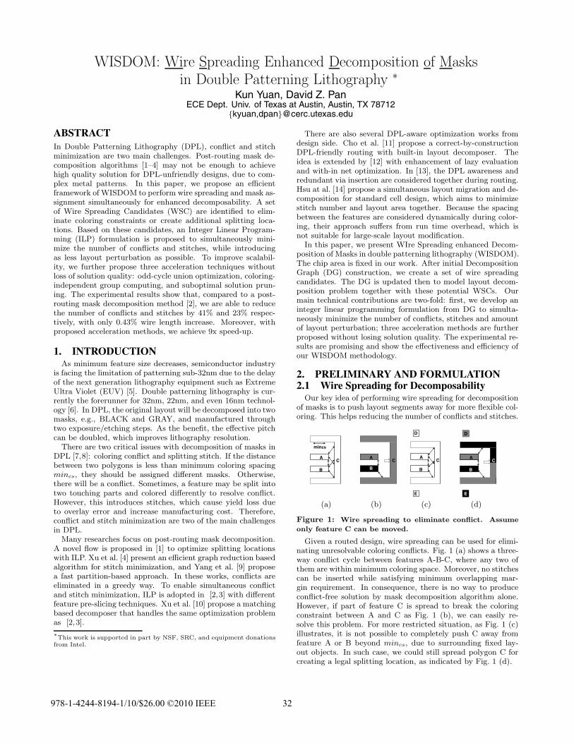
Figure 1: Wire spreading to eliminate conflict. Assume
only feature C can be moved.
Given a routed design, wire spreading can be used for elimi-nating unresolvable coloring conflicts. Fig. 1 (a) shows a three-way conflict cycle between features A-B-C, where any two ofthem are within minimum coloring space. Moreover, no stitchescan be inserted while satisfying minimum overlapping mar-gin requirement. In consequence, there is no way to produceconflict-free solution by mask decomposition algorithm alone.However, if part of feature C is spread to break the coloringconstraint between A and C as Fig. 1 (b), we can easily re-solve this problem. For more restricted situation, as Fig. 1 (c)illustrates, it is not possible to completely push C away fromfeature A or B beyond mincs, due to surrounding fixed lay-out objects. In such case, we could still spread polygon C forcreating a legal splitting location, as indicated by Fig. 1 (d).
978-1-4244-819 - /10/$26.00 ©2010 IEEE 324 1
A
B
CD
E
(a)
A
BC
D
E
(b)
Figure 2: Wire spreading to reduce stitch. Assume only
feature C can be moved.
It is also possible to spread wire to reduce the number ofstitches. For the example in Fig. 2 (a), initially, feature C isnot splittable, and two stitches are required on A and D forresolving conflicts. If we spread the route C as Fig. 2 (b), onlyone stitch is needed.
2.2 Problem FormulationAs it can be seen from Section 2.1, with help of wire spread-
ing, the solution space of DPL decomposition can be extraor-dinarily high. On the other hand, as nanometer designs aremostly grid-based, that restricts wire spreading to its nearbydiscrete routing grids. Therefore, we will preprocess the initialdecomposition graph and generate a library of Wire SpreadingCandidates (WSC)s to improve decomposability (more detaileddescription to be presented in Section 3.2). Mask assignment isperformed together with these candidates as options. As exam-ples, Fig. 1 (b)/(d) and Fig. 2 (a) are simple WSCs for Fig. 1(a)/(c) and Fig. 2 (f), respectively.
With this library of WSCs, our optimization problem is for-mally defined as follows:
Problem Formulation: Given a layout, perform mask de-composition with pre-computed WSCs as design modificationoptions. The goal is to minimize the number of conflicts andstitches, while introducing as less layout perturbation as possi-ble.
ILP Formulation(Odd-Cycle Union Optimization)
Coloring-Independent Group Computing
(Suboptimal Solution Pruning)
Decomposition Graph Initialization
Wire Spreading Candidate Generation and Modeling in Decomposition Graph
Figure 3: The overview of WISDOM
3. BASIC ALGORITHMS FOR WISDOMIn following two sections, we will present our WISDOM al-
gorithm. The entire flow is shown in Figure 3.
3.1 Decomposition Graph InitializationFor simplification purpose, we adopt a flow similar to [2]
to construct an initial DG for modeling mask decompositionproblem. Other approaches as in [3, 4] are also flexible to ap-ply. There are two kinds of edges: Conflict Edge (CE) andStitch Edge (SE). If and only if two nodes(polygons) are con-nected by CE/SE and in same/different masks, it results in aconflict/stitch.
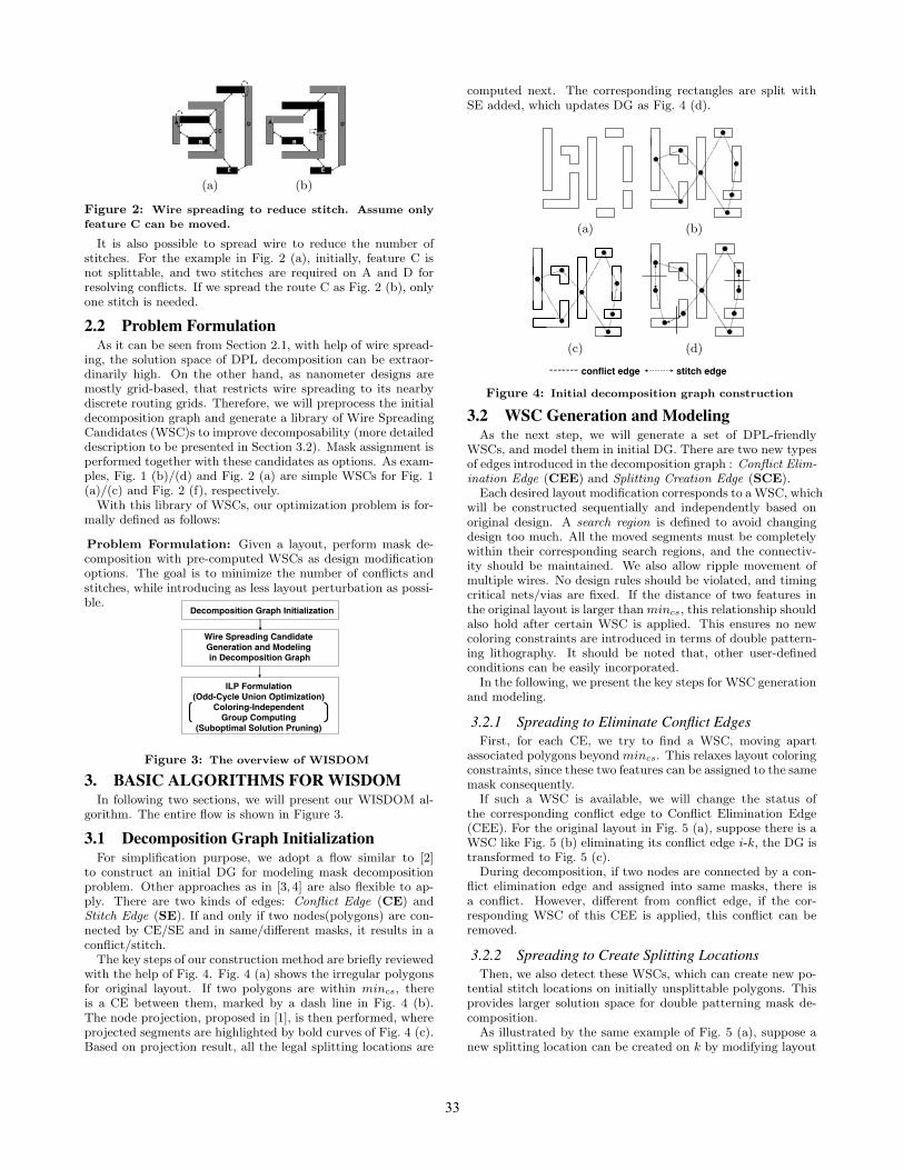
The key steps of our construction method are briefly reviewedwith the help of Fig. 4. Fig. 4 (a) shows the irregular polygonsfor original layout. If two polygons are within mincs, thereis a CE between them, marked by a dash line in Fig. 4 (b).The node projection, proposed in [1], is then performed, whereprojected segments are highlighted by bold curves of Fig. 4 (c).Based on projection result, all the legal splitting locations are
computed next. The corresponding rectangles are split withSE added, which updates DG as Fig. 4 (d).
(a) (b)
(c) (d)
conflict edge stitch edge
Figure 4: Initial decomposition graph construction
3.2 WSC Generation and ModelingAs the next step, we will generate a set of DPL-friendly
WSCs, and model them in initial DG. There are two new typesof edges introduced in the decomposition graph : Conflict Elim-ination Edge (CEE) and Splitting Creation Edge (SCE).
Each desired layout modification corresponds to a WSC, whichwill be constructed sequentially and independently based onoriginal design. A search region is defined to avoid changingdesign too much. All the moved segments must be completelywithin their corresponding search regions, and the connectiv-ity should be maintained. We also allow ripple movement ofmultiple wires. No design rules should be violated, and timingcritical nets/vias are fixed. If the distance of two features inthe original layout is larger than mincs, this relationship shouldalso hold after certain WSC is applied. This ensures no newcoloring constraints are introduced in terms of double pattern-ing lithography. It should be noted that, other user-definedconditions can be easily incorporated.
In the following, we present the key steps for WSC generationand modeling.
3.2.1 Spreading to Eliminate Conflict EdgesFirst, for each CE, we try to find a WSC, moving apart
associated polygons beyond mincs. This relaxes layout coloringconstraints, since these two features can be assigned to the samemask consequently.
If such a WSC is available, we will change the status ofthe corresponding conflict edge to Conflict Elimination Edge(CEE). For the original layout in Fig. 5 (a), suppose there is aWSC like Fig. 5 (b) eliminating its conflict edge i-k, the DG istransformed to Fig. 5 (c).
During decomposition, if two nodes are connected by a con-flict elimination edge and assigned into same masks, there isa conflict. However, different from conflict edge, if the cor-responding WSC of this CEE is applied, this conflict can beremoved.
3.2.2 Spreading to Create Splitting LocationsThen, we also detect these WSCs, which can create new po-
tential stitch locations on initially unsplittable polygons. Thisprovides larger solution space for double patterning mask de-composition.
As illustrated by the same example of Fig. 5 (a), suppose anew splitting location can be created on k by modifying layout
33
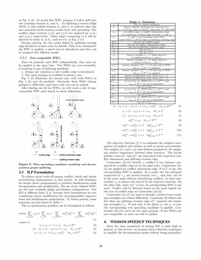
as Fig. 5 (d). To model this WSC, polygon k is first split intotwo touching features ki and kj . An Splitting Creation Edge(SCE) is then added between ki and kj to indicate that thisnew potential stitch location results from wire spreading. Theconflict edges between (i, k) and (j, k) are replaced by (i, ki)and (j, kj) respectively. Other edges connecting to k will bedirected to either ki or kj , such as o-kj in Fig. 5 (e).
During coloring, the two nodes linked by splitting creatingedge should be in same color by default. Only if its correspond-ing WSC is applied, a stitch can be introduced and they canbe assigned into different masks.
3.2.3 Non-compatible WSCsSince we generate each WSC independently, they may not
be applied in the same time. Two WSCs are non-compatible,if resulting in any of following problems:
1. Design rule violation or new conflict edge is introduced.2. The same polygon is modified in distinct way.Fig. 5 (f) illustrates the second case, with both WSCs in
Fig. 5 (b) and (d) modeled. Obviously, these WSCs changepolygon k differently, and hence only one can be picked.
After finding out all the WSCs, we will create a list of non-compatible WSC pairs based on above definitions.
(a) (b) (c)
j
k
o
i
j
k
o
i
j
k
o
iConflict Elimination Edge
(d) (e) (f)
j o
i
j
ik
o
i
jk j
ik
o
i
jk
Sp
litting
creation
edg
e
conflict edge
splitting creation edge
conflict elimination edge
Figure 5: Wire spreading candidate modeling and decom-
position graph updating.
3.3 ILP FormulationTo achieve good trade-off among conflict, stitch and layout
perturbation minimization, in this section, we will formulatean integer linear programming to perform simultaneous maskdecomposition and modification. The set of pre defined WSCsare the only available design pertubation configurations. OurILP is different from [1, 3], because their formulations are notconsidering layout modification for decomposability improve-ment and simultaneous optimization. To better present, somenotations are first listed in Table 1.
The co-optimization problem can be formulated as follows:
min(α∑
eij∈E
cij+ε∑
tij∈T
sij+∑
eij∈Ecee
mceeij pcee
ij +∑
eij∈Esce
msceij psce
ij )
(1)subject to
xi + xj <= 1 + cij ∀eij ∈ Ece (2)
(1 − xi) + (1 − xj) <= 1 + cij ∀eij ∈ Ece (3)
xi + xj <= 1 + cij + mceeij ∀eij ∈ Ecee (4)
Table 1: Notationri The ith layout polygonsxi binary variable denoting the coloring of ri
xi = 0 if the color is GRAY, otherwise it is BLACKeij a conflict edge, a conflict elimination edge
or a splitting creation edge between ri and rj
tij ri and rj are touching each other,connected by a stitch edge or splitting creating edge
Ece the set of conflict edgesEcee the set of conflict elimination edgesEsce the set of splitting creation edges
E the set of eij
T the set of tij
cij binary variable cij =1 when there isa conflict between ri and rj
sij binary variable sij =1 when there isa stitch between ri and rj
mceeij binary variable mcee
ij = 1 if and only if WSCfor eij ∈ Ecee is applied
msceij binary variable msce
ij = 1 if and only if WSCfor eij ∈ Esce is applied
pceeij layout modification cost, when mcee
ij =1
psceij layout modification cost, when msce
ij =1
yccij,mn (i, j) �= (m, n). WSCs for eij ∈ Ecee and
emn ∈ Ecee are not compatible.Y cc the set of ycc
ij,mn
yssij,mn (i, j) �= (m, n). WSCs for eij ∈ Esce and
emn ∈ Esce are not compatible.Y ss the set of yss
ij,mn
ycsij,mn (i, j) �= (m, n). WSCs for eij ∈ Ecee and
emn ∈ Esce are not compatible.Y cs the set of ycs
ij,mn
(1 − xi) + (1 − xj) <= 1 + cij + mceeij ∀eij ∈ Ecee (5)
xi + (1 − xj) <= 1 + sij ∀tij ∈ T (6)
(1 − xi) + xj <= 1 + sij ∀tij ∈ T (7)
msceij = sij ∀eij ∈ Esce (8)
mceeij + mcee
mn <= 1 ∀yccij,mn ∈ Y cc (9)
msceij + msce
mn <= 1 ∀yssij,mn ∈ Y ss (10)
mceeij + msce
mn <= 1 ∀ycsij,mn ∈ Y cs (11)
The objective function (1) is to minimize the weighted sum-mation of conflicts and stitches as well as layout perturbation.The weights of α and ε are user-defined parameters, for assign-ing relative importance between these matrices. The layoutpenalty costs pcee
ij and psceij are associated with respective con-
flict elimination and splitting creation edge.Constraints (2)-(3) identify a conflict if two features con-
nected by a conflict edge are in the same color. Constraints (4)-(5) are applied for conflict elimination edge. If mcee
ij is one, thecorresponding WSC is applied. As a result, the two polygonsconnected by eij are moved beyond mincs, and they can bein the same mask without introducing conflicts. In such case,variable cij is always zero forced by the objective function. Onthe other side, when mcee
ij is zero, its corresponding WSC is notused. Conflict will be detected based on the same logistic forthe case of conflict edge as Constraints (2)-(3).
Constraints (6)-(7) are used to identify a stitch if two touch-ing rectangles are colored differently. Constraint (8) follows thefact that any splitting creation edge esce
ij connects two touch-ing rectangles tij . If and only if the stitch sij for tij is one,the corresponding wire spreading candidate is applied. Con-straints (9)-(11) serve for the same purpose. If two WSCs arenot compatible, at most one will be picked.
4. WISDOM SPEEDUP TECHNIQUESSince the time complexity of solving ILP is quite high in
general, in this section, we propose three reduction techniquesto simplify the decomposition graph without losing optimality.
34
Definition 1 odd/even cycle (OC/EC): a cycle, whose totalnumber of conflict edges and conflict elimination edges is odd/even.
4.1 Odd-Cycle Union OptimizationNaively, ILP formulation would be performed on the entire
decomposition graph. In this section, we will show that, it issufficient to conduct ILP only on a subgraph of the DG, whichis the union of all the odd-cycles. It will not lose optimality.
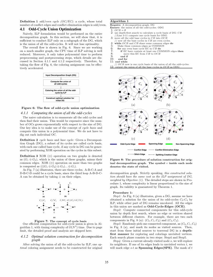
The overall flow is shown in Fig. 6. Since we are workingon a much smaller graph, the CPU time of ILP solving is wellreduced. Moreover, it only takes polynomial time to performpreprocessing and postprocessing steps, which details are dis-cussed in Section 4.1.1 and 4.1.2 respectively. Therefore, bytaking the flow of Fig. 6, the coloring assignment can be effec-tively accelerated.
Coloring the union of all the odd-cycle by ILP
Input Decomposition Graph (DG)
Compute the union of all odd-cycles
Construct optimal solution for initial DG
Figure 6: The flow of odd-cycle union optimization
4.1.1 Computing the union of all the odd-cyclesThe naive calculation is to enumerate all the odd cycles and
then find their union. This would be expensive since the num-ber of OCs grows exponentially with respect to the size of DG.Our key idea is to make use of the concept of cycle basis andcompute this union in a polynomial time. We do not have todig out each individual OC.
Definition 2 cycle basis and base cycle: Given a Decomposi-tion Graph (DG), a subset of its cycles are called cycle basis,with each one called base cycle, if any cycle in DG can be gener-ated by performing XOR operation on the cycles in this subset.
Definition 3 XOR (⊕) operation on two graphs is denotedas (G1 ⊕ G2), which is the union of these graphs, minus theircommon edges. XOR (⊕) operation on more than two graphsis computed as (((G1 ⊕ G2) ⊕ G3)... ⊕ Gi).
As Fig. 7 (a) illustrates, there are three cycles. A-B-C-A andD-B-C-D could be a cycle basis, since the third loop A-B-D-C-A can be obtained by taking ⊕ on their edges.
A
B
C
D ⊕
B
C
B
C
D
A
B
C
DA
B
C
D
B
C
1 2C C∪ 1 2C C∩ 1 2 1 2 1 2: ( ) \ ( )C C C C C C⊕ ∪ ∩
1C 2C
(a) (b)
(c)
A
Figure 7: The concept of cycle basisOur efficient computation for odd-cycle union is given in Al-
gorithm 1, with timing complexity of O(N3) time. Due to pagelimit, the detailed proof and analysis are skipped here.
4.1.2 Optimal solution construction for decompositiongraph
After solving the union of all the odd-cycles by ILP, one op-timal coloring assignment needs to be constructed for original
Algorithm 1Require: A decomposition graph, DGEnsure: the union of all the odd-cycles: ODG1: OCB = ∅2: use depth-first search to calculate a cycle basis of DG: CB
//Line 3-11 compute one cycle basis for ODG.3: move all the odd base cycles in CB into OCB
// now all the base cycles in CB are even cycles.4: while OCB and CB share some common edges do5: Make these common edges as COMMON6: for any even base cycle EC in CB do7: if EC have contain at least one COMMON edges then8: move this EC from CB to OCB9: end if10: end for11: end while
// OCB now is one cycle basis of the union of all the odd-cycles.12: output the union of all the base cycles in OCB as ODG
V V
VV
V
v
V
A BC
D
E
S
V
V1C
3C
2C0C
(a)
V V
VV
V
v
V
A BC
D
E
S
V
V1C
3C
2C0C
4CV
?
(b)
V V
VV
VVV
A BC
D
E
S
V
v
V
V
V
V1C
3C
2C0C
4CVV
(c)
V V
VV
VV
AE
S
V
v
V
V
V
V1C
3C
2C0C
4CVV
V V
VB
C
DS
V
(d)
Odd-Cycle Edge Spanning Edge Non-Spanning Edge
Conflict Edge
Splitting Creation Edge
Conflict Elimination Edge
Stitch Edge
Figure 8: The procedure of solution construction for orig-
inal decomposition graph. The symbol v inside each node
denotes the state of visited.
decomposition graph. Strictly speaking, this constructed solu-tion should have the same cost as the ILP assignment of DG,weighted by Objective (1). The detailed steps are shown in Pro-cedure 1, whose complexity is linear proportional to the size ofgraph. Its validity is guaranteed by Theorem 1.
Procedure 1:Step1: As Fig. 8 (a) illustrates, given a DG, assume we have
obtained a solution for the union of its odd-cycles C0-C4 byILP, while other part of DG remains uncolored. All the edgesin this union are marked as Odd-Cycle-Edges (OCE).
Step2: Compute connected components for this odd-cycleunion by depth first search, where no edge or vertices sharedbetween different clusters. For example, there are two suchcomponents in Fig. 8 (a): (C0, C1, C2) and (C3, C4).
Step3: Randomly pick one connected component, as (C0, C1, C2)in Fig. 8 (a), and mark its nodes as visited sources. Then,start from these initial sources to traversal DG in a depth-first manner for exploring and colorings unvisited vertices.Each search phase consists in two steps: Step4 and Step5.
Step4: Given a current already-visited node s, we will exploreits neighbors. If one of its edges leads to unvisited vertex t, wewill mark edge s-t as Spanning Edges(SPE). The mask of t
35
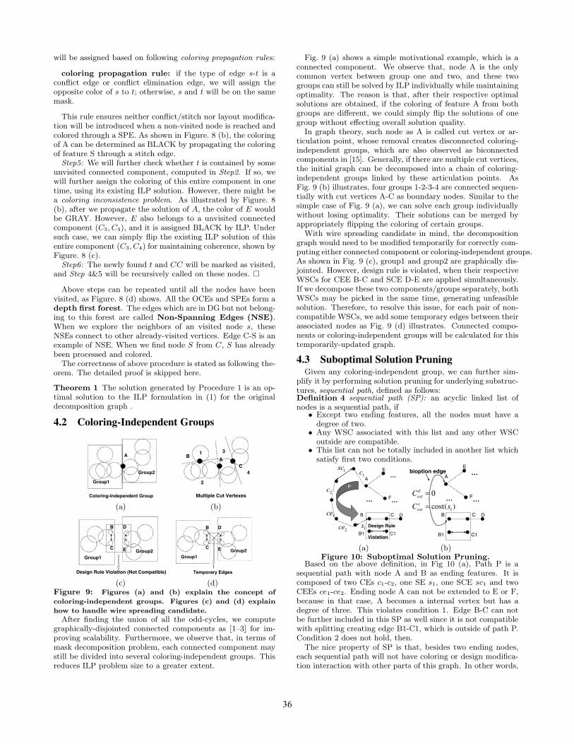
will be assigned based on following coloring propagation rules:
coloring propagation rule: if the type of edge s-t is aconflict edge or conflict elimination edge, we will assign theopposite color of s to t; otherwise, s and t will be on the samemask.
This rule ensures neither conflict/stitch nor layout modifica-tion will be introduced when a non-visited node is reached andcolored through a SPE. As shown in Figure. 8 (b), the coloringof A can be determined as BLACK by propagating the coloringof feature S through a stitch edge.
Step5: We will further check whether t is contained by someunvisited connected component, computed in Step2. If so, wewill further assign the coloring of this entire component in onetime, using its existing ILP solution. However, there might bea coloring inconsistence problem. As illustrated by Figure. 8(b), after we propagate the solution of A, the color of E wouldbe GRAY. However, E also belongs to a unvisited connectedcomponent (C3, C4), and it is assigned BLACK by ILP. Undersuch case, we can simply flip the existing ILP solution of thisentire component (C3, C4) for maintaining coherence, shown byFigure. 8 (c).
Step6: The newly found t and CC will be marked as visited,and Step 4&5 will be recursively called on these nodes. �
Above steps can be repeated until all the nodes have beenvisited, as Figure. 8 (d) shows. All the OCEs and SPEs form adepth first forest. The edges which are in DG but not belong-ing to this forest are called Non-Spanning Edges (NSE).When we explore the neighbors of an visited node s, theseNSEs connect to other already-visited vertices. Edge C-S is anexample of NSE. When we find node S from C, S has alreadybeen processed and colored.
The correctness of above procedure is stated as following the-orem. The detailed proof is skipped here.
Theorem 1 The solution generated by Procedure 1 is an op-timal solution to the ILP formulation in (1) for the originaldecomposition graph .
4.2 Coloring-Independent Groups
A
Group1
Group2
Coloring-Independent Group
(a)
Multiple Cut Vertexes
AB
C
1
2
3
4
(b)
D
Group1Group2E
B
C
Design Rule Violation (Not Compatible)
(c)
D
Group1Group2E
B
C
Temporary Edges
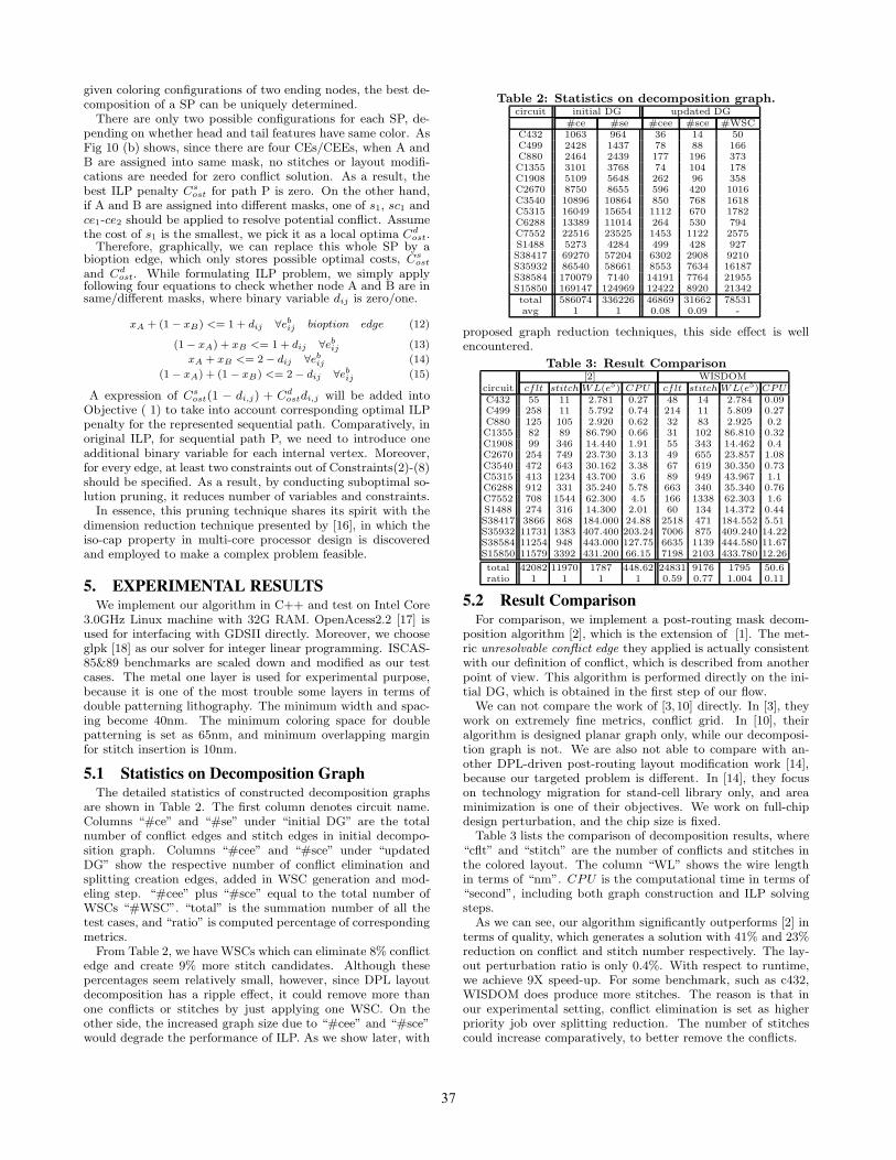
(d)Figure 9: Figures (a) and (b) explain the concept of
coloring-independent groups. Figures (c) and (d) explain
how to handle wire spreading candidate.
After finding the union of all the odd-cycles, we computegraphically-disjointed connected components as [1–3] for im-proving scalability. Furthermore, we observe that, in terms ofmask decomposition problem, each connected component maystill be divided into several coloring-independent groups. Thisreduces ILP problem size to a greater extent.
Fig. 9 (a) shows a simple motivational example, which is aconnected component. We observe that, node A is the onlycommon vertex between group one and two, and these twogroups can still be solved by ILP individually while maintainingoptimality. The reason is that, after their respective optimalsolutions are obtained, if the coloring of feature A from bothgroups are different, we could simply flip the solutions of onegroup without effecting overall solution quality.
In graph theory, such node as A is called cut vertex or ar-ticulation point, whose removal creates disconnected coloring-independent groups, which are also observed as biconnectedcomponents in [15]. Generally, if there are multiple cut vertices,the initial graph can be decomposed into a chain of coloring-independent groups linked by these articulation points. AsFig. 9 (b) illustrates, four groups 1-2-3-4 are connected sequen-tially with cut vertices A-C as boundary nodes. Similar to thesimple case of Fig. 9 (a), we can solve each group individuallywithout losing optimality. Their solutions can be merged byappropriately flipping the coloring of certain groups.
With wire spreading candidate in mind, the decompositiongraph would need to be modified temporarily for correctly com-puting either connected component or coloring-independent groups.As shown in Fig. 9 (c), group1 and group2 are graphically dis-jointed. However, design rule is violated, when their respectiveWSCs for CEE B-C and SCE D-E are applied simultaneously.If we decompose these two components/groups separately, bothWSCs may be picked in the same time, generating unfeasiblesolution. Therefore, to resolve this issue, for each pair of non-compatible WSCs, we add some temporary edges between theirassociated nodes as Fig. 9 (d) illustrates. Connected compo-nents or coloring-independent groups will be calculated for thistemporarily-updated graph.
4.3 Suboptimal Solution PruningGiven any coloring-independent group, we can further sim-
plify it by performing solution pruning for underlying substruc-tures, sequential path, defined as follows:Definition 4 sequential path (SP): an acyclic linked list ofnodes is a sequential path, if
• Except two ending features, all the nodes must have adegree of two.
• Any WSC associated with this list and any other WSCoutside are compatible.
• This list can not be totally included in another list whichsatisfy first two conditions.
A
B
P
P2
E
F
B1 C1
… …
…
DC
1s
1ce
2c
1sc1c
2ce Design Rule
Violation
(a)
A
B
P2
E
F
B1 C1
… …
…
D1
0
cost( )
dost
sost
C
C s
=
=
P
bioption edge
C
(b)Figure 10: Suboptimal Solution Pruning.
Based on the above definition, in Fig 10 (a), Path P is asequential path with node A and B as ending features. It iscomposed of two CEs c1-c2, one SE s1, one SCE sc1 and twoCEEs ce1-ce2. Ending node A can not be extended to E or F,because in that case, A becomes a internal vertex but has adegree of three. This violates condition 1. Edge B-C can notbe further included in this SP as well since it is not compatiblewith splitting creating edge B1-C1, which is outside of path P.Condition 2 does not hold, then.
The nice property of SP is that, besides two ending nodes,each sequential path will not have coloring or design modifica-tion interaction with other parts of this graph. In other words,
36
given coloring configurations of two ending nodes, the best de-composition of a SP can be uniquely determined.
There are only two possible configurations for each SP, de-pending on whether head and tail features have same color. AsFig 10 (b) shows, since there are four CEs/CEEs, when A andB are assigned into same mask, no stitches or layout modifi-cations are needed for zero conflict solution. As a result, thebest ILP penalty Cs
ost for path P is zero. On the other hand,if A and B are assigned into different masks, one of s1, sc1 andce1-ce2 should be applied to resolve potential conflict. Assumethe cost of s1 is the smallest, we pick it as a local optima Cd
ost.Therefore, graphically, we can replace this whole SP by a
bioption edge, which only stores possible optimal costs, Csost
and Cdost. While formulating ILP problem, we simply apply
following four equations to check whether node A and B are insame/different masks, where binary variable dij is zero/one.
xA + (1 − xB) <= 1 + dij ∀ebij bioption edge (12)
(1 − xA) + xB <= 1 + dij ∀ebij (13)
xA + xB <= 2 − dij ∀ebij (14)
(1 − xA) + (1 − xB) <= 2 − dij ∀ebij (15)
A expression of Csost(1 − di,j) + Cd
ostdi,j will be added intoObjective ( 1) to take into account corresponding optimal ILPpenalty for the represented sequential path. Comparatively, inoriginal ILP, for sequential path P, we need to introduce oneadditional binary variable for each internal vertex. Moreover,for every edge, at least two constraints out of Constraints(2)-(8)should be specified. As a result, by conducting suboptimal so-lution pruning, it reduces number of variables and constraints.
In essence, this pruning technique shares its spirit with thedimension reduction technique presented by [16], in which theiso-cap property in multi-core processor design is discoveredand employed to make a complex problem feasible.
5. EXPERIMENTAL RESULTSWe implement our algorithm in C++ and test on Intel Core
3.0GHz Linux machine with 32G RAM. OpenAcess2.2 [17] isused for interfacing with GDSII directly. Moreover, we chooseglpk [18] as our solver for integer linear programming. ISCAS-85&89 benchmarks are scaled down and modified as our testcases. The metal one layer is used for experimental purpose,because it is one of the most trouble some layers in terms ofdouble patterning lithography. The minimum width and spac-ing become 40nm. The minimum coloring space for doublepatterning is set as 65nm, and minimum overlapping marginfor stitch insertion is 10nm.
5.1 Statistics on Decomposition GraphThe detailed statistics of constructed decomposition graphs
are shown in Table 2. The first column denotes circuit name.Columns “#ce” and “#se” under “initial DG” are the totalnumber of conflict edges and stitch edges in initial decompo-sition graph. Columns “#cee” and “#sce” under “updatedDG” show the respective number of conflict elimination andsplitting creation edges, added in WSC generation and mod-eling step. “#cee” plus “#sce” equal to the total number ofWSCs “#WSC”. “total” is the summation number of all thetest cases, and “ratio” is computed percentage of correspondingmetrics.
From Table 2, we have WSCs which can eliminate 8% conflictedge and create 9% more stitch candidates. Although thesepercentages seem relatively small, however, since DPL layoutdecomposition has a ripple effect, it could remove more thanone conflicts or stitches by just applying one WSC. On theother side, the increased graph size due to “#cee” and “#sce”would degrade the performance of ILP. As we show later, with
Table 2: Statistics on decomposition graph.circuit initial DG updated DG
#ce #se #cee #sce #WSCC432 1063 964 36 14 50C499 2428 1437 78 88 166C880 2464 2439 177 196 373C1355 3101 3768 74 104 178C1908 5109 5648 262 96 358C2670 8750 8655 596 420 1016C3540 10896 10864 850 768 1618C5315 16049 15654 1112 670 1782C6288 13389 11014 264 530 794C7552 22516 23525 1453 1122 2575S1488 5273 4284 499 428 927S38417 69270 57204 6302 2908 9210S35932 86540 58661 8553 7634 16187S38584 170079 7140 14191 7764 21955S15850 169147 124969 12422 8920 21342total 586074 336226 46869 31662 78531avg 1 1 0.08 0.09 -
proposed graph reduction techniques, this side effect is wellencountered.
Table 3: Result Comparison[2] WISDOM
circuit cflt stitch WL(e5) CPU cflt stitch WL(e5) CPUC432 55 11 2.781 0.27 48 14 2.784 0.09C499 258 11 5.792 0.74 214 11 5.809 0.27C880 125 105 2.920 0.62 32 83 2.925 0.2C1355 82 89 86.790 0.66 31 102 86.810 0.32C1908 99 346 14.440 1.91 55 343 14.462 0.4C2670 254 749 23.730 3.13 49 655 23.857 1.08C3540 472 643 30.162 3.38 67 619 30.350 0.73C5315 413 1234 43.700 3.6 89 949 43.967 1.1C6288 912 331 35.240 5.78 663 340 35.340 0.76C7552 708 1544 62.300 4.5 166 1338 62.303 1.6S1488 274 316 14.300 2.01 60 134 14.372 0.44S38417 3866 868 184.000 24.88 2518 471 184.552 5.51S35932 11731 1383 407.400 203.24 7006 875 409.240 14.22S38584 11254 948 443.000 127.75 6635 1139 444.580 11.67S15850 11579 3392 431.200 66.15 7198 2103 433.780 12.26
total 42082 11970 1787 448.62 24831 9176 1795 50.6ratio 1 1 1 1 0.59 0.77 1.004 0.11
5.2 Result ComparisonFor comparison, we implement a post-routing mask decom-
position algorithm [2], which is the extension of [1]. The met-ric unresolvable conflict edge they applied is actually consistentwith our definition of conflict, which is described from anotherpoint of view. This algorithm is performed directly on the ini-tial DG, which is obtained in the first step of our flow.
We can not compare the work of [3,10] directly. In [3], theywork on extremely fine metrics, conflict grid. In [10], theiralgorithm is designed planar graph only, while our decomposi-tion graph is not. We are also not able to compare with an-other DPL-driven post-routing layout modification work [14],because our targeted problem is different. In [14], they focuson technology migration for stand-cell library only, and areaminimization is one of their objectives. We work on full-chipdesign perturbation, and the chip size is fixed.
Table 3 lists the comparison of decomposition results, where“cflt” and “stitch” are the number of conflicts and stitches inthe colored layout. The column “WL” shows the wire lengthin terms of “nm”. CPU is the computational time in terms of“second”, including both graph construction and ILP solvingsteps.
As we can see, our algorithm significantly outperforms [2] interms of quality, which generates a solution with 41% and 23%reduction on conflict and stitch number respectively. The lay-out perturbation ratio is only 0.4%. With respect to runtime,we achieve 9X speed-up. For some benchmark, such as c432,WISDOM does produce more stitches. The reason is that inour experimental setting, conflict elimination is set as higherpriority job over splitting reduction. The number of stitchescould increase comparatively, to better remove the conflicts.
37
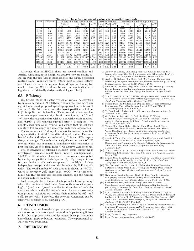
Table 4: The effectiveness of various acceleration methodscircuit CPU(base) odd-cycle union optimization +c-independent +suboptimal solution pruning
#nodes #edges CPU #CC #CG CPU #var #con CPUw/o w w/o w w/o w w/o w w/o w
C432 0.35 2350 715 3398 798 0.26 127 138 0.22 1596 792 1502 914 0.09C499 1.2 3996 1539 7485 1926 0.78 164 180 0.55 3854 1933 3449 2013 0.27C880 0.64 5525 2195 6562 2428 0.57 293 311 0.64 4864 1904 4604 2254 0.2C1355 0.87 7893 3084 9633 7893 0.67 551 585 0.82 6482 2796 6291 3449 0.32C1908 2.26 12122 4709 15321 12122 1.35 635 699 1.52 10366 4578 9828 5497 0.4C2670 2.96 18784 8788 23875 18784 2.05 916 977 2.93 20078 8849 18765 10229 1.08C3540 4.53 23878 10108 29925 23878 2.61 1196 1227 2.77 22784 9092 21469 10603 0.73C5315 3.91 34556 15245 44201 17320 2.92 1779 1920 2.18 34650 14567 32424 17056 1.1C6288 5.82 29192 8460 40968 9181 3.03 1266 1668 4.89 18368 8006 17239 9486 0.76C7552 5.22 50650 21565 62801 24029 4.14 2716 2869 1.27 48066 20061 45441 23769 1.6S1488 1.38 10538 4752 9771 5430 1.2 585 622 1.38 100680 4046 10050 4686 0.44S38417 27.54 141535 47592 127928 52660 14.67 5791 6989 12.53 105342 44790 99055 5222 5.51S35932 223.56 311931 139035 149018 152925 57.51 17123 20960 29.58 305906 131384 288123 147123 14.22S38584 129.85 338771 117352 181101 131147 49.46 13241 16605 27.97 262388 114148 245135 126849 11.67S15850 83.32 326454 132463 298576 147940 41.93 14960 18207 31.73 295942 123066 277157 137241 12.26total 493.41 1318175 517602 1010563 608461 183.15 61343 73957 120.98 1241366 490012 1080532 506391 50.65ratio 1 1 0.39 1 0.60 0.37 1 1.20 0.24 1 0.39 1 0.47 0.1
Although after WISDOM, there are several conflicts andstitches remaining in the design, we observe they are mainly re-sulting from the pins/vias in standard cells and highly-congestedrouting paths. While we search WSCs, most of these featuresare set as fixed for avoiding modifying design and timing toomuch. Thus, our WISDOM can be used in combination withhigh-level DPL-friendly design methodologies [11–14].
5.3 EfficiencyWe further study the effectiveness of various acceleration
techniques in Table 4. “CPU(base)” shows the runtime of ouralgorithm without proposed speed-up approaches, in terms of“seconds”. For fair comparison, the layout partition techniquein [2] is applied in this baseline. Then, we add in each acceler-ation technique incrementally. In all the columns, “w/o” and“w” show the respective data without and with certain method,and “CPU” is the resulting runtime after it is adopted. Wedouble check simulation results, and ensure that no solutionquality is lost by applying these graph reduction approaches.
The columns under “odd-cycle union optimization” show thegraph statistics of initial DG and its odd-cycle union. The num-ber of nodes and edges are reduced by 61% and 40% respec-tively in average. This reduction is significant in terms of ILPsolving, which has exponential complexity with respective toproblem size. As seen from Table 4, we achieve 2.7x speed-up.
The effectiveness of coloring-dependent group computing isinvestigated then with results listed under “+c-independent”.“#CC” is the number of connected components, computedby the layout partition technique in [2]. By using cut ver-tex, we further divide each component to multiple coloring-independent groups, which can also be solved by ILP individ-ually. The total number of such groups is shown in “#CG”,which is averagely 20% more than “#CC”. With this tech-nique, the ILP problem size becomes smaller, and the runtimeis further reduced by 37%.
Last, we apply the technique of suboptimal solution pruning,where the results are listed under “+suboptimal solution prun-ing”. “#var” and “#con” are the total number of variablesand constraints in the ILP formulations. As we can see, solu-tion pruning technique can reduce their number by 61% and53%, respectively. Therefore, the coloring assignment can beeffectively accelerated by another 2.4X.
6. CONCLUSIONIn this paper, we have developed a wire spreading enhanced
decomposition of masks algorithm for double patterning lithog-raphy. Our approach is featured by integer linear programmingand efficient graph reduction techniques. The experimental re-sults are very promising.
7. REFERENCES
[1] Andrew B. Kahng, Chul-Hong Park, Xu Xu, and Hailong Yao.Layout decomposition for double patterning lithography. In Proc.Int. Conf. on Computer Aided Design, November 2008.
[2] Andrew B. Kahng, Chul-Hong Park, Xu Xu, and Hailong Yao.Revisiting the layout decomposition problem for double patterninglithography. In Proc. of SPIE, October 2008.
[3] Kun Yuan, Jae-Seok Yang, and David Z. Pan. Double patterninglayout decomposition for simultaneous conflict and stitchminimization. In Proc. Int. Symp. on Physical Design, March2009.
[4] Yue Xu and Chris Chu. GREMA: Graph Reduction based EfficientMask Assignment for double patterning lithography. In Proc. Int.Conf. on Computer Aided Design, Nov 2009.
[5] Micrea Dusa, Jo Finders, and Stephen Hsu. Double patterninglithography: The bridge between low k1 ArF and EUV. InMicrolithography World, Feb 2008.
[6] Y. Borodovsky. Lithography 2009 overview of opportunities. InSemicon West, 2009.
[7] G. Bailey, A. Tritchkov, J. Park, L. Hong, V. Wiaux,E. Hendrickx, S. Verhaegen, P. Xie, and J. Versluijs. Doublepattern EDA solutions for 32nm HP and beyond. In Proc. ofSPIE, volume 6521, 2007.
[8] Tsann-Bim Chiou, Robert Socha, Hong Chen, Luoqi Chen,Stephen Hsu, Peter Nikolsky, Anton van Oosten, and Alek C.Chen. Development of layout split algorithms and printabilityevaluation for double patterning technology. In Proc. of SPIE,March 2008.
[9] Jae-Seok Yang, Katria Lu, Minsik Cho, Kun Yuan, and David Z.Pan. A New Graph-theoretic, Multi-objective LayoutDecomposition Framework for Double Patterning Lithography. InProc. Asia and South Pacific Design Automation Conf.,Janunary 2010.
[10] Yue Xu and Chris Chu. A Matching Based Decomposer for DoublePatterning Lithography. In Proc. Int. Symp. on Physical Design,March 2010.
[11] Minsik Cho, Yongchan Ban, and David Z. Pan. Double patterningtechnology friendly detailed routing. In Proc. Int. Conf. onComputer Aided Design, October 2008.
[12] Xin Gao and Luca Macchiarulo. Enhancing Double-PatterningDetailed Routing With Lazy Coloring and Within-Path ConflictAvoidance. In Proc. Design, Automation and Test in Eurpoe,March 2010.
[13] Kun Yuan, Katrina Lu, and David Z. Pan. Double patterninglithography friendly detailed routing with redundant viaconsideration. In Proc. Design Automation Conf., July 2009.
[14] Chin-Hsiung Hsu, Yao-Wen Chang, and Sani R. Nassif.Simultanous layout migration and decomposition for doublepatterning technology. In Proc. Int. Conf. on Computer AidedDesign, November 2009.
[15] Piotr Bermany, Andrew B. Kahng, Devendra Vidhani, HuijuanWang, and Alexander Zelikovsky. Optimal Phase Conflict Removalfor Layout of Dark Field Alternating Phase Shifting Masks. IEEETrans. on Computer-Aided Design of Integrated Circuits andSystems, 19(2):175–187, Feb 2000.
[16] Yifang Liu, Weiping Shi, and Jiang Hu. Buffering Interconnect forMulticore Processor Designs. IEEE Trans. on Computer-AidedDesign of Integrated Circuits and Systems, 27(12):2183–2196,December 2008.
[17] http://www.si2.org/?page=69.
[18] http://www.gnu.org/software/glpk/glpk.html/.
38