Embed Size (px)
Citation preview
Wisconsin Highway Research Program
Guidance, Parameters, and Recommendations for Rubblized Pavements
SPR# 0092-05-07
Harold L. Von Quintus, Chetana Rao, Jagannath Mallela and Brian Aho
Applied Research Associates, Inc.
January 2007
WHRP 06-13
GUIDANCE, PARAMETERS, AND RECOMMENDATIONS FOR RUBBLIZED
PAVEMENTS
Final Report Report No. WHRP 06-13 (ARA Project No. 16730)
Submitted to: Wisconsin Highway Research Program 1415 Engineering Drive, Room 2218
Madison, Wisconsin 53706
Prepared by: Harold L. Von Quintus, P.E.
Chetana Rao Jagannath Mallela
Brian Aho Applied Research Associates, Inc.
102 Northwest Drive, Suite C Round Rock, Texas 78664
January 2007
i
ACKNOWLEDGEMENTS
This report was prepared under sponsorship from the Wisconsin Department of Transportation through the Wisconsin Highway Research Program. The research team acknowledges the participation and support received from the Technical Oversight Committee project point, Signe Reichelt of Payne and Dolan, Inc., individuals with the Wisconsin Department of Transportation. The department’s Quality Management Section, Data Management Unit, and individuals from the Regional/District offices provided much of the data used within this study.
DISCLAIMER
This research was funded through the Wisconsin Highway Research Program by the Wisconsin Department of Transportation and the Federal Highway Administration under Project #0092-00-07. The contents of this report reflect the views of the authors who are responsible for the facts and accuracy of the data presented herein. The contents do not necessarily reflect the official views of the Wisconsin Department of Transportation or the Federal Highway Administration at the time of publication.
This document is disseminated under the sponsorship of the Department of Transportation in the interest of information exchange. The United States Government assumes no liability for its contents or use thereof. This report does not constitute a standard, specification, or regulation.
The United States Government does not endorse products or manufacturers. Trade and manufacturers’ names appear in this report only because they are considered essential to the objective of the document.
ii
Technical Report Documentation Page 1. Report No. WHRP 06-13
Government Accession No 3. Recipient’s Catalog No
4. Title and Subtitle Guidance, Parameters, and Recommendations for Rubblized Pavements
5. Report Date January 2007 6. Performing Organization Code
7. Authors Von Quintus, Harold L., Chetana Rao, Jagannath Mallela, and Brian Aho
8. Performing Organization Report No.
Project No. 16730 9. Performing Organization Name and Address Applied Research Associates, Inc. 102 Northwest Drive, Suite C Round Rock, Texas 78664
10. Work Unit No. (TRAIS)
11. Contract or Grant No. WisDOT SPR# 0092-05-07
12. Sponsoring Agency Name and Address Wisconsin Department of Transportation Division of Business Services Research Coordination Section 4802 Sheboygan Ave. Rm 801 Madison, WI 53707
13. Type of Report and Period Covered
Final Report, 2004-2006
14. Sponsoring Agency Code
15. Supplementary Notes
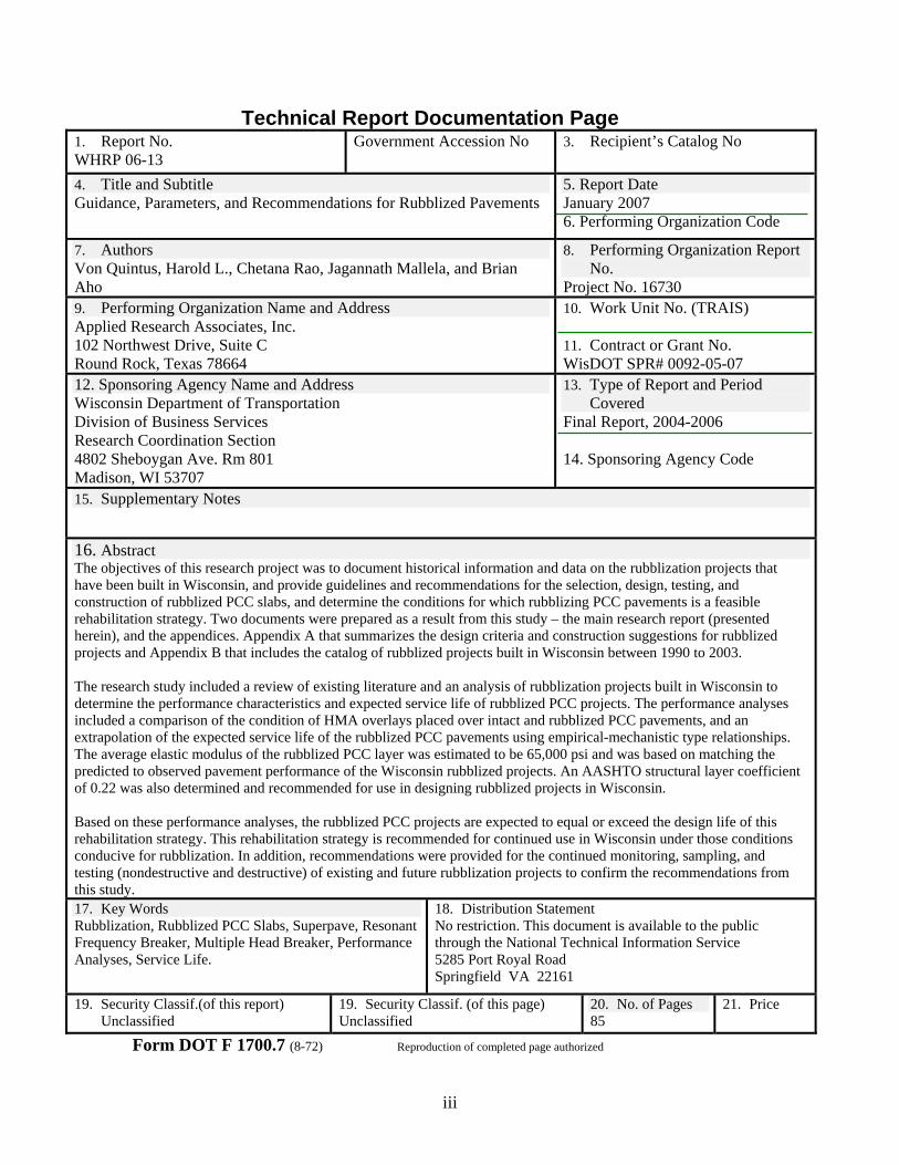
16. Abstract The objectives of this research project was to document historical information and data on the rubblization projects that have been built in Wisconsin, and provide guidelines and recommendations for the selection, design, testing, and construction of rubblized PCC slabs, and determine the conditions for which rubblizing PCC pavements is a feasible rehabilitation strategy. Two documents were prepared as a result from this study – the main research report (presented herein), and the appendices. Appendix A that summarizes the design criteria and construction suggestions for rubblized projects and Appendix B that includes the catalog of rubblized projects built in Wisconsin between 1990 to 2003.
The research study included a review of existing literature and an analysis of rubblization projects built in Wisconsin to determine the performance characteristics and expected service life of rubblized PCC projects. The performance analyses included a comparison of the condition of HMA overlays placed over intact and rubblized PCC pavements, and an extrapolation of the expected service life of the rubblized PCC pavements using empirical-mechanistic type relationships. The average elastic modulus of the rubblized PCC layer was estimated to be 65,000 psi and was based on matching the predicted to observed pavement performance of the Wisconsin rubblized projects. An AASHTO structural layer coefficient of 0.22 was also determined and recommended for use in designing rubblized projects in Wisconsin.
Based on these performance analyses, the rubblized PCC projects are expected to equal or exceed the design life of this rehabilitation strategy. This rehabilitation strategy is recommended for continued use in Wisconsin under those conditions conducive for rubblization. In addition, recommendations were provided for the continued monitoring, sampling, and testing (nondestructive and destructive) of existing and future rubblization projects to confirm the recommendations from this study. 17. Key Words Rubblization, Rubblized PCC Slabs, Superpave, Resonant Frequency Breaker, Multiple Head Breaker, Performance Analyses, Service Life.
18. Distribution Statement No restriction. This document is available to the public through the National Technical Information Service 5285 Port Royal Road Springfield VA 22161
19. Security Classif.(of this report) Unclassified
19. Security Classif. (of this page) Unclassified
20. No. of Pages 85
21. Price
Form DOT F 1700.7 (8-72) Reproduction of completed page authorized
iii
TABLE OF CONTENTS
Chapter Page
LIST OF TABLES .................................................................................................................... v LIST OF FIGURES ...................................................................................................................vi
1 INTRODUCTION ............................................................................................................. 1 1.1 Background............................................................................................................ 1 1.2 Study Objectives .................................................................................................... 2 1.3 Scope of Report and Study .................................................................................... 2
2 RUBBLIZATION STUDIES AND USE – AN OVERVIEW .......................................... 4 2.1 Definition and Purpose of Rubblization ................................................................ 4 2.2 Rubblization Useage .............................................................................................. 4 2.3 Wisconsin’s Use of Rubblization........................................................................... 5 2.4 Historical Studies and Projects .............................................................................. 6 2.5 Costs of Rubblization Process ............................................................................. 18 2.6 Summary of Concerns from Previous Studies ..................................................... 20
3 REHABILITATION DESIGN GUIDELINES AND PRACTICES ............................... 22 3.1 Factors to Consider in Evaluating the Rubblization Process for a Particular
Project .................................................................................................................. 22 3.2 Material Properties of the Rubblized Layer for Use in Rehabilitation
Design .................................................................................................................. 23 3.3 Rubblization Design Features .............................................................................. 26 3.4 HMA Overlay Thickness Design Requirements and Criteria.............................. 29
4 CONSTRUCTION PRACTICES AND SPECIFICATIONS.......................................... 33 4.1 Equipment Requirements and Operation ............................................................. 33 4.2 Rubblization Criteria – Material Requirements/Specifications ........................... 38 4.3 Seating and Rolling Requirements....................................................................... 39 4.4 Construction Sequence and Requirements........................................................... 40 4.5 Construction Specifications and Quality Assurance............................................ 44
5 PERFORMANCE ANALYSES OF WISCONSIN RUBBLIZATION PROJECTS ...... 47 5.1 Identification of Wisconsin Rubblized Projects .................................................. 48 5.2 Performance Indicators Used in Analysis............................................................ 48 5.3 Analysis Performance Data.................................................................................. 53 5.4 Summary of Findings from Performance Analysis ............................................. 67
6 SUMMARY OF FINDINGS AND CONCLUSIONS .................................................... 69 6.1 Findings and Conclusions .................................................................................... 69 6.2 Recommendations................................................................................................ 73
iv

TABLE OF CONTENTS (Continued)
REFERENCES .................................................................................................................. 75
APPENDICES (Included as Separate Documents) A Guidelines for Designing and Constructing Rubblized PCC Pavements ...................... A.1 B Performance History and Details of the Rubblized Projects and Segments in
Wisconsin ................................................................................................................ B.1
v
LIST OF TABLES
Table Table Caption Page No. No.
1 Relative Level of Use of the Rubblization Process by State Agencies.............................. 5 2 Wisconsin Rubblization Projects ....................................................................................... 7 3 LTPP SPS-6 Projects that Include Rubblization Test Sections ....................................... 14 4 Calculated Modulus Values for Selected Military Airfield Project (Source:
ERDC) .................................................................................................................. 26 5 Wisconsin Rubblization Projects and Segments Included in the Performance
Analysis .................................................................................................................. 50 6 Summary of the Average Service Life Extrapolated from the Performance Data
for Each Performance Indicator ....................................................................................... 63 7 Average Service Life for Different Conditions for the Rubblized Projects in
Wisconsin .................................................................................................................. 67
vi

LIST OF FIGURES
Figure Figure Caption Page No. No.
1 Amount of cracking on the LTPP SPS-6 rubblized test sections..................................... 15 2 Rubblization unit prices extracted from Wisconsin’s database between 1998 and
2004 .................................................................................................................. 19 3 Wisconsin rubblization unit prices over time .................................................................. 20 4 Typical edge drain system placed prior to the rubblization process................................ 27 5 FWD deflection basins measured on rubblized PCC airport pavement at different
times during the rubblization process .............................................................................. 28 6 Illinois DOT design thickness chart for HMA overlay for varying traffic factor
values .................................................................................................................. 30 7 Photo of the resonant frequency pavement breaker for rubblizing PCC slabs ................ 34 8 Photo of the multiple drop hammer for rubblizing PCC slabs......................................... 34 9 Graphical illustration of the selection of rubblization equipment type, as specified
by the Illinois DOT .......................................................................................................... 36 10 Effect of compaction on deflection basin; Grand Forks AFB ......................................... 40 11 Typical particle size distribution specifications for the two major competing
rubblization techniques (Velez-Vega, 2005) ................................................................... 45 12 RMI bulk modulus test on rubblized PCC highway pavement........................................ 45 13 Rubblized PCC projects completed over time in Wisconsin ........................................... 47 14 Histogram of the most recent PDI values determined for the rubblized projects in
Wisconsin .................................................................................................................. 54 15 Histogram of the most recent rut depths measured on the rubblized projects in
Wisconsin .................................................................................................................. 54 16 Histogram of the most recent IRI values measured on the rubblized projects in
Wisconsin .................................................................................................................. 55 17 Graphical illustration of the increase in HMA overlay thickness placed on
rubblized PCC slabs over time......................................................................................... 55 18 Average PDI values with project age for the rubblized projects ..................................... 56 19 Average rut depths with project age for the rubblized projects ....................................... 56 20 Average IRI values with project age for the rubblized projects ...................................... 57 21 Comparison between the average PDI and IRI values for the same rubblized
segments .................................................................................................................. 57 22 Effect of interlayer on the average PDI value.................................................................. 58 23 Effect of interlayer on the average rut depth ................................................................... 59 24 Effect of interlayer on the average IRI value................................................................... 59 25 Effect of overlay thickness on the average PDI............................................................... 60 26 ffect of overlay thickness on the average rut depth ......................................................... 60 27 ffect of overlay thickness on the average IRI value......................................................... 61 28 Predicted and measured PDI values for the rubblization project in Dane County
along SH-51, 1996 construction ...................................................................................... 63
vii
LIST OF FIGURES (Continued)
Figure Figure Caption Page No. No. 29 Average rut depth measured on each rubblization project by construction year or
date of rehabilitation ........................................................................................................ 64 30 Comparison between PDI values measured on rubblized segments and on
companion segments with other rehabilitation strategies ................................................ 64 31 Comparison between IRI values measured on rubblized segments and on
companion segments with other rehabilitation strategies ................................................ 65 32 Comparison between rut depths measured on rubblized segments and on
companion segments with other rehabilitation strategies ................................................ 65
viii
GUIDANCE, PARAMETERS AND RECOMMENDATIONS FOR RUBBLIZED PAVEMENTS
CHAPTER 1 INTRODUCTION
1.1 Background
A significant portion of our nation’s aging highway infrastructure is now beyond the design and serviceability for which it was designed and constructed, and is in need of repair. With reported savings in cost and construction time, rubblization of Portland cement concrete (PCC) slabs has become a rehabilitation strategy that many agencies are now using instead of total reconstruction for heavily distressed rigid pavements. More importantly, reflection cracking is a major problem in hot mix asphalt (HMA) overlays placed over intact PCC slabs, even when used in combination with other repair techniques (such as, slab-jacking, partial and full-depth slab replacement, etc.). Reflection cracks can start to appear in the HMA overlay within a few years after overlay placement. These reflection cracks then have to be sealed and maintained to prevent further deterioration of the HMA overlay.
The objective of rubblizing PCC slabs is to eliminate reflection cracking in an HMA overlay by destroying the integrity of the existing slab. This objective is achieved by fracturing the PCC slab in place into fragments of nominal three to eight-inch size or less, while retaining good interlock between the fractured particles. This process has been termed rubblization and is applicable to jointed plain concrete (JPC), jointed reinforced concrete (JRC), and continuously reinforced concrete (CRC) pavements. Reinforcing steel in JRC and CRC pavements must become debonded from the PCC slab when using this approach. Rubblization also offers economic benefits by reducing costs associated with hauling and disposal of the existing PCC slabs.
Colorado, Indiana, Illinois, Michigan, Ohio, Pennsylvania, and Wisconsin are a few states that have built demonstration projects using the rubblization process. Based on these demonstration projects, agencies like Alabama, Arkansas, and Michigan Department of Transportation (DOT) have made a decision to consider rubblization as one of their primary rehabilitation strategies of rigid pavements on heavily traveled roadways. Similarly, the Wisconsin DOT has selected and used this option on almost eighty PCC rehabilitation projects since 1990. Although the use of rubblizing PCC slabs as a viable rehabilitation strategy has increased significantly over the past decade, there have been few field and theoretical studies to determine the important parameters and factors that have a significant effect on the performance characteristics of this repair technique for rigid pavements.
The Wisconsin DOT specifications provide guidelines for acceptable maximum particle sizes after rubblization and give field engineers discretion to allow for larger particle sizes. To date, however, there have been no documented studies from Wisconsin, nor any other agency, that address the relationship between post-rubblized particle size
1
distribution and pavement performance. In addition, standard guidelines do not exist for engineering analyses of the pavement to determine the expected benefits of rubblization. Thus, the Wisconsin DOT has identified an important need to document the performance and construction histories of the rubblized projects that have been constructed to date and to prepare design and construction guidelines to maximize the benefit from this rehabilitation strategy. Without proper guidance, pavement designers may discount rubblization as a viable option for a specific project and the reported savings will not be realized. Conversely, a project can be selected for the rubblization process that has features not well-suited for this option.
1.2 Study Objectives
Stated simply, there are two objectives of this study, which are listed below
1. Document historical information and data on the rubblization projects that have been built in Wisconsin.
2. Provide guidelines and recommendations for the selection, design, testing, and construction of rubblized PCC slabs, and determine the conditions for which rubblizing PCC pavements is a feasible rehabilitation strategy.
1.3 Scope of Report and Study
The project activities were divided into three basic tasks – (1) information gathering and review, (2) preparation of a historical catalog of Wisconsin rubblization projects, and (3) performance analyses of these projects. All data used within this study was extracted from the Wisconsin pavement management system, available construction records, and discussion with construction personnel. Pavement and materials testing were outside the scope of this study. The activities completed within this study were designed to answer the following basic questions:
• What parameters should be considered in determining if rubblization is a feasible alternative or rehabilitation strategy for PCC pavements?
• What values of the design inputs should be used for determining HMA overlay thickness using the 1993 AASHTO Design Guide and mechanistic-based design procedures, such as the Mechanistic-Empirical (M-E) Pavement Design Guide developed under NCHRP 1-37A?
• What problems have been encountered and solutions applied during construction using this type of repair strategy of PCC pavements?
• What tests, the frequency of those tests, and inspection methods are needed during the rubblization and HMA overlay process, if different from current construction specifications and Quality Assurance (QA) procedures?
• What data are needed to monitor and confirm the performance and design guidelines of this rehabilitation strategy?
• Is the rubblization of PCC pavements a cost-effective rehabilitation strategy (i.e., when compared to other rehabilitation strategies)?
2
This report documents the results and findings from a literature review of previous studies, a review of state agency design procedures and construction specifications, and an analysis of the performance data on the rubblization projects completed within Wisconsin. The report is divided into six chapters, including Chapter 1 – the Introduction. Chapter 2 provides an overview of previous rubblization studies and projects, while Chapter 3 identifies the rubblization design and construction parameters considered important to the long-term performance of this rehabilitation strategy. Chapter 4 overviews and discusses the rubblization construction practices and specifications used by those agencies that have extensive experience with the rubblization process. Chapter 5 presents the analyses completed on the Wisconsin rubblized projects, and Chapter 6 is the conclusions and recommendations from this study.
3
CHAPER 2 RUBBLIZATION STUDIES AND USE – AN OVERVIEW
Since rubblization is a relatively new rehabilitation strategy, there are few projects that have recorded the performance of rubblized pavement, or investigated causes for the lack of good performance. Most studies have concluded, through the use of limited data, that rubblization is a viable technology for rehabilitating PCC pavements (Fitts, 2001), and have refined their specifications based on these limited performance studies. More importantly, many of the studies have alluded to the need for a good quality control program during the construction stage to achieve long term performance.
An overview of the design and construction specifications of those agencies that have used this process for many years is provided in Chapters 3 and 4. The purpose of this chapter is to provide an overview of studies and demonstration projects that have focused on the rubblization process – both its benefits and concerns of use.
2.1 Definition and Purpose of Rubblization
Rubblization has been successful in many highway and airport projects around the United States. Experience in the highway industry has shown that rubblization can be an effective technique for rehabilitation of PCC pavements. The process eliminates all slab action by breaking the PCC into small particles ranging from sand size to 75 mm (3 in) at the surface and 300 to 380 mm (12 to 15 in) on the bottom part of the rubblized layer. More importantly, rubblization is environmentally friendly and can result in cost and time savings because it utilizes the old PCC material as a structural layer.
The rubblized layer responds as an interlocked unbound layer – reducing the existing PCC to a material comparable to a high-quality aggregate base course. The fractured slab eliminates reflective cracking in HMA overlays by minimizing thermal expansion and contraction of the PCC slabs. An issue that has continually plagued industry, however, is how large can the PCC particles be and still eliminate reflection cracking. Conversely, is there a limit to the lower size of these particles (other than economics and practicality) where the rubblized layer’s strength is significantly reduced – loosing a key benefit. The documents reviewed and data collected within this study attempt to answer these types of questions, as noted in Chapter 1.
2.2 Rubblization Usage
The Asphalt Institute recently reported that more than 50 million square yards of U.S. highways were successfully rubblized between 1994 and 2002. Almost 75 percent of the highway agencies in the U.S. have completed some rubblization projects, since the first project in New York in 1986. Table 1 lists those agencies and the approximate number of rehabilitation projects that have used the rubblization process. This technique also has been implemented in the countries of Canada, Russia, Yugoslavia, Chile, and China.
4
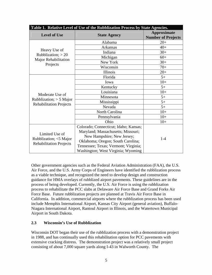
Table 1. Relative Level of Use of the Rubblization Process by State Agencies.
Level of Use State Agency Approximate Number of Projects
Heavy Use of Rubblization; > 20
Major Rehabilitation Projects
Alabama 20+ Arkansas 40+ Indiana 30+
Michigan 60+ New York 30+ Wisconsin 70+
Illinois 20+
Moderate Use of Rubblization; > 5 Major Rehabilitation Projects
Florida 5+ Iowa 10+
Kentucky 5+ Louisiana 10+ Minnesota 5+ Mississippi 5+
Nevada 5+ North Carolina 10+ Pennsylvania 10+
Ohio 10+
Limited Use of Rubblization; <5 Major Rehabilitation Projects
Colorado; Connecticut; Idaho; Kansas; Maryland; Massachusetts; Missouri;
New Hampshire; New Jersey; Oklahoma; Oregon; South Carolina;
Tennessee; Texas; Vermont; Virginia; Washington; West Virginia; Wyoming
1-4
Other government agencies such as the Federal Aviation Administration (FAA), the U.S. Air Force, and the U.S. Army Corps of Engineers have identified the rubblization process as a viable technique, and recognized the need to develop design and construction guidance for HMA overlays of rubblized airport pavements. These guidelines are in the process of being developed. Currently, the U.S. Air Force is using the rubblization process to rehabilitate the PCC slabs at Delaware Air Force Base and Grand Forks Air Force Base. Future rubblization projects are planned at Travis Air Force Base in California. In addition, commercial airports where the rubblization process has been used include Memphis International Airport, Kansas City Airport (general aviation), Buffalo-Niagara International Airport, Rantoul Airport in Illinois, and the Watertown Municipal Airport in South Dakota.
2.3 Wisconsin’s Use of Rubblization
Wisconsin DOT began their use of the rubblization process with a demonstration project in 1988, and has continually used this rehabilitation option for PCC pavements with extensive cracking distress. The demonstration project was a relatively small project consisting of about 7,000 square yards along I-43 in Walworth County. The
5
demonstration project showed that the process was viable, and was followed by a rubblization project along State Highway (SH) 16 in Waukesha County in 1990. After that first actual project in 1990, three were completed in 1992 and three in 1993. The use of this technology has steadily increased in Wisconsin since 1995.
Prior to 1996, most of the rubblization projects included the Resonant Frequency Breaker (RFB), while after 1996 all of the projects included the use of a Multiple Head Breaker (refer to Table 2). Wisconsin also included the use of a leveling or cushion course above the rubblized PCC slabs on some of the projects completed after 1996. This leveling course consists of millings, recycled asphalt pavement (RAP), or aggregate materials.
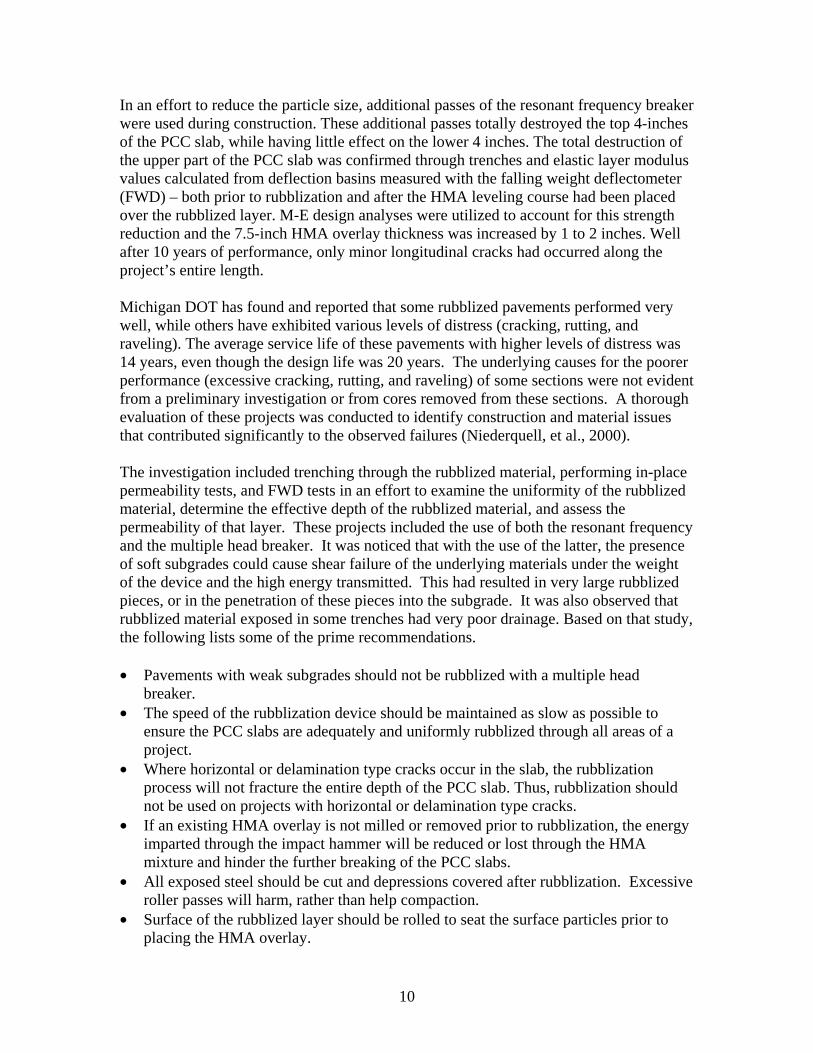
Through 2004, the Wisconsin DOT has successfully completed almost eighty projects. Table 2 lists the known projects that have been built in Wisconsin. Chapter 5 discusses the performance of some of these projects. In summary, it is expected that the performance of the projects will exceed their design lives based on performance data and observations collected to date.
2.4 Historical Studies and Projects
NAPA – 1994 NAPA completed a study in 1994, entitled Guidelines for the Use of Overlays to Rehabilitate PCC Pavements, to determine the modulus value for rubblized PCC slabs, as well as for the crack and seat and break and seat methods. The modulus values reported and recommended for use in design in that study were high; exceeding 100,000 psi, which result in fairly thin HMA overlays (less than 3.0 inches in thickness). The performance of these thin HMA overlays over rubblized PCC slabs has yet to be confirmed with sufficient field data. In fact, some agencies (for example, Colorado, Michigan, and Pennsylvania DOT) have reported early cracking in these thin HMA overlays. Other agencies have established minimum HMA overlay thickness requirements (as low as 4.0 inches) when placed on rubblized PCC slabs.
Michigan DOT - 2000 Michigan started implementing the rubblization process to rehabilitate deteriorated PCC slabs from as early as 1986, and was one of the first agencies to develop a specification for PCC pavement rubblization. Several States used this specification to build their own agency-specific requirements for rubblization.
On one of the first Michigan projects where the rubblization process was used (US Highway 23 in Washtenaw Country), the contractor (Thompson-McCully) had difficulty reducing the size of the PCC pieces to values less than 6-inches through the 9-inch slab thickness. Probable causes for this problem were related to weak soils, a high water table, and different type aggregate between the bottom and surface of the PCC slabs. A drainage layer was not included as a design feature to dry-out the soils, even though it had been recommended.
6
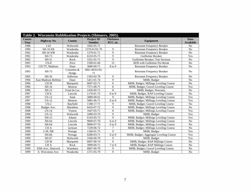
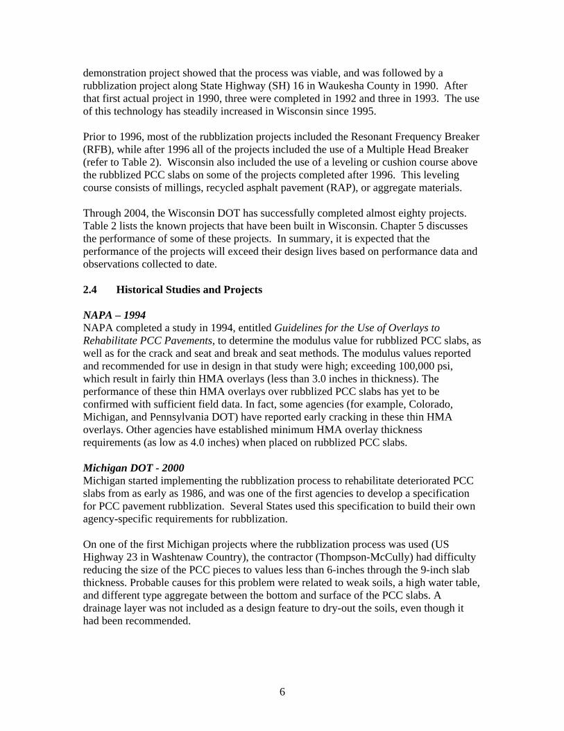
Table 2. Wisconsin Rubblization Projects (Shinners, 2005). Constr.
Year Highway No. County Project ID Number
Thickness PCC, in. Equipment Data
Available 1988 I-43 Walworth 1092-05-71 Resonant Frequency Breaker No 1990 SH-16 EB Waukesha 1370-01/02-70 9 Resonant Frequency Breaker No 1992 SH-16 WB Waukesha 1370-01-71 9 Resonant Frequency Breaker No 1992 SH-73 Waukesha 6310-05-71 9 Guillotine Breaker Yes 1992 SH-51 Rock 5351-01-71 9 Guillotine Breaker; Test Sections No 1993 US-8 Price 1589-01-60 15 RFB with Guillotine Pre-Break No 1993 CH TT, Madison Dane 3680-00-71 8 to 9 Resonant Frequency Breaker No
1993 SH-73 Columbia & Dodge
3061-00/01/0271 Resonant Frequency Breaker No
1995 SH-26 Jefferson 1393-02-78 9 Resonant Frequency Breaker No 1996 East Madison Beltline Dane 5411-01-74 9 MHB, Badger No 1996 CH M Marquette 6697-02-71 6 MHB, Badger; Millings Leveling Course No 1996 SH-16 Monroe 7571-08-71 8 MHB, Badger; Gravel Leveling Course Yes 1996 SH-23 Fond du Lac 1430-00-71 8 MHB, Badger; Warranty No 1997 CH K Lincoln 1176-01-75 6 to 9 MHB, Badger; RAP Leveling Course No 1997 US-12 Sauk 5880-00-61 9 MHB, Badger; Millings Leveling Course Yes 1997 US-12 Monroe 5881-06-71 6 to 9 MHB, Badger; Millings Leveling Course Yes 1998 US-2 Bayfield 1180-17-71 9 MHB, Badger; Gravel Leveling Course No 1998 Badger Ave. Marathon 6410-07-72 9 MHB, Badger; Millings Leveling Course No 1998 US-14 Vemon 1647-05-71 8 MHB, Badger; Millings Leveling Course Yes 1998 US-12 Walworth 1080-03-70 9 MHB, Badger Yes 1999 SH-13 Adams 6143-05-72 9 MHB, Badger; Millings Leveling Course Yes 1999 SH-64 Lincoln 9000-07-70 6 to 9 MHB, Badger; Millings Leveling Course No 1999 SH-64 Lincoln 9000-07-70 6 to 9 MHB, Badger; Millings Leveling Course No 1999 CH A Jackson 7239-06-72 7 MHB, Badger; Millings Leveling Course No 1999 I-39, NB Portage 1160-01-75 9 MHB, Badger Yes 1999 SH-66 Portage 6280-03-71 6 to 9 MHB, Badger; Aggregate Leveling Course Yes 1999 SH-67 Walworth 3160-00-70 9 MHB, Badger Yes 1999 CH M Marquette 6697-00-74 6 MHB, Badger; RAP Millings Course No 1999 CH X Rock 3999-00-71 7 to 9 MHB, Badger; RAP Millings Course No 1999 Fifth Ave.; Hancock Waushara 6867-00-70 9 MHB, Badger; Gravel Leveling Course No 1999 E. Wisconsin Ave. Waukesha 1371-05-70 9 MHB, Badger No
7
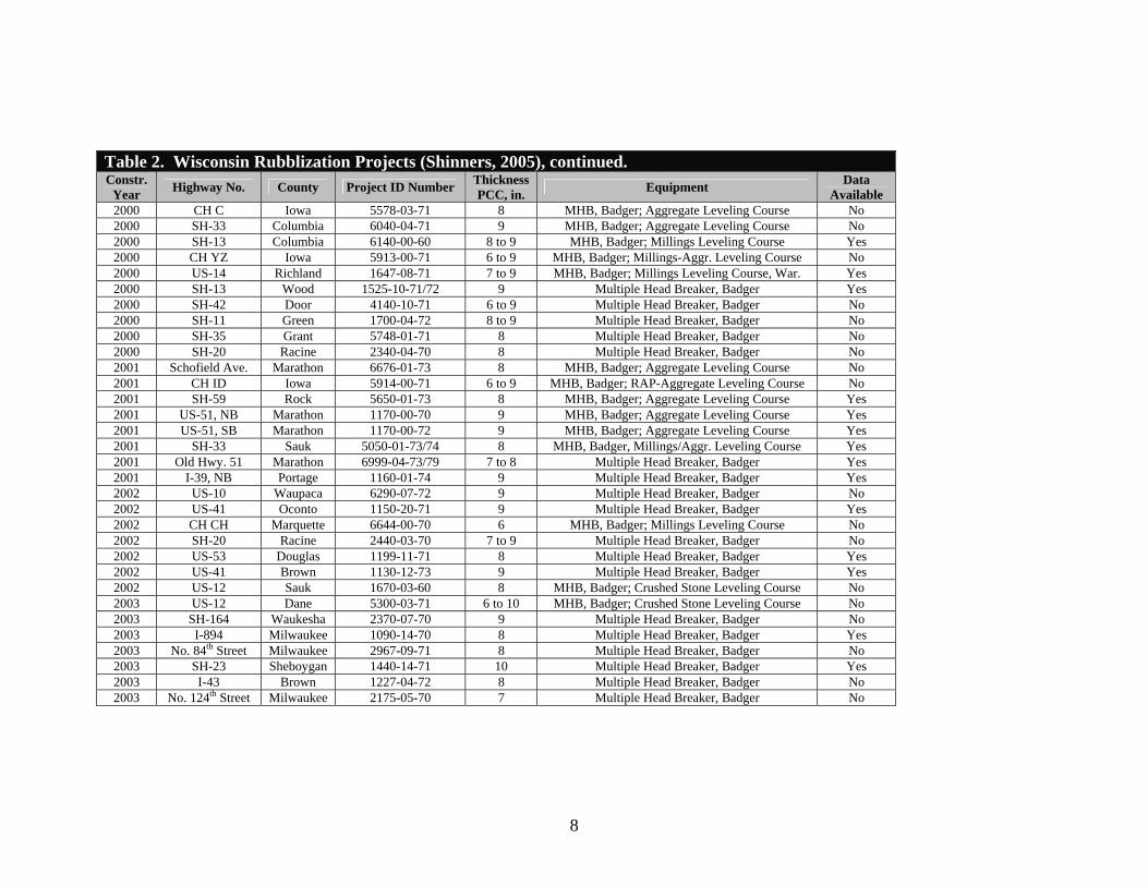
Table 2. Wisconsin Rubblization Projects (Shinners, 2005), continued. Constr.
Year Highway No. County Project ID Number Thickness PCC, in. Equipment Data
Available 2000 CH C Iowa 5578-03-71 8 MHB, Badger; Aggregate Leveling Course No 2000 SH-33 Columbia 6040-04-71 9 MHB, Badger; Aggregate Leveling Course No 2000 SH-13 Columbia 6140-00-60 8 to 9 MHB, Badger; Millings Leveling Course Yes 2000 CH YZ Iowa 5913-00-71 6 to 9 MHB, Badger; Millings-Aggr. Leveling Course No 2000 US-14 Richland 1647-08-71 7 to 9 MHB, Badger; Millings Leveling Course, War. Yes 2000 SH-13 Wood 1525-10-71/72 9 Multiple Head Breaker, Badger Yes 2000 SH-42 Door 4140-10-71 6 to 9 Multiple Head Breaker, Badger No 2000 SH-11 Green 1700-04-72 8 to 9 Multiple Head Breaker, Badger No 2000 SH-35 Grant 5748-01-71 8 Multiple Head Breaker, Badger No 2000 SH-20 Racine 2340-04-70 8 Multiple Head Breaker, Badger No 2001 Schofield Ave. Marathon 6676-01-73 8 MHB, Badger; Aggregate Leveling Course No 2001 CH ID Iowa 5914-00-71 6 to 9 MHB, Badger; RAP-Aggregate Leveling Course No 2001 SH-59 Rock 5650-01-73 8 MHB, Badger; Aggregate Leveling Course Yes 2001 US-51, NB Marathon 1170-00-70 9 MHB, Badger; Aggregate Leveling Course Yes 2001 US-51, SB Marathon 1170-00-72 9 MHB, Badger; Aggregate Leveling Course Yes 2001 SH-33 Sauk 5050-01-73/74 8 MHB, Badger, Millings/Aggr. Leveling Course Yes 2001 Old Hwy. 51 Marathon 6999-04-73/79 7 to 8 Multiple Head Breaker, Badger Yes 2001 I-39, NB Portage 1160-01-74 9 Multiple Head Breaker, Badger Yes 2002 US-10 Waupaca 6290-07-72 9 Multiple Head Breaker, Badger No 2002 US-41 Oconto 1150-20-71 9 Multiple Head Breaker, Badger Yes 2002 CH CH Marquette 6644-00-70 6 MHB, Badger; Millings Leveling Course No 2002 SH-20 Racine 2440-03-70 7 to 9 Multiple Head Breaker, Badger No 2002 US-53 Douglas 1199-11-71 8 Multiple Head Breaker, Badger Yes 2002 US-41 Brown 1130-12-73 9 Multiple Head Breaker, Badger Yes 2002 US-12 Sauk 1670-03-60 8 MHB, Badger; Crushed Stone Leveling Course No 2003 US-12 Dane 5300-03-71 6 to 10 MHB, Badger; Crushed Stone Leveling Course No 2003 SH-164 Waukesha 2370-07-70 9 Multiple Head Breaker, Badger No 2003 I-894 Milwaukee 1090-14-70 8 Multiple Head Breaker, Badger Yes 2003 No. 84th Street Milwaukee 2967-09-71 8 Multiple Head Breaker, Badger No 2003 SH-23 Sheboygan 1440-14-71 10 Multiple Head Breaker, Badger Yes 2003 I-43 Brown 1227-04-72 8 Multiple Head Breaker, Badger No 2003 No. 124th Street Milwaukee 2175-05-70 7 Multiple Head Breaker, Badger No
8
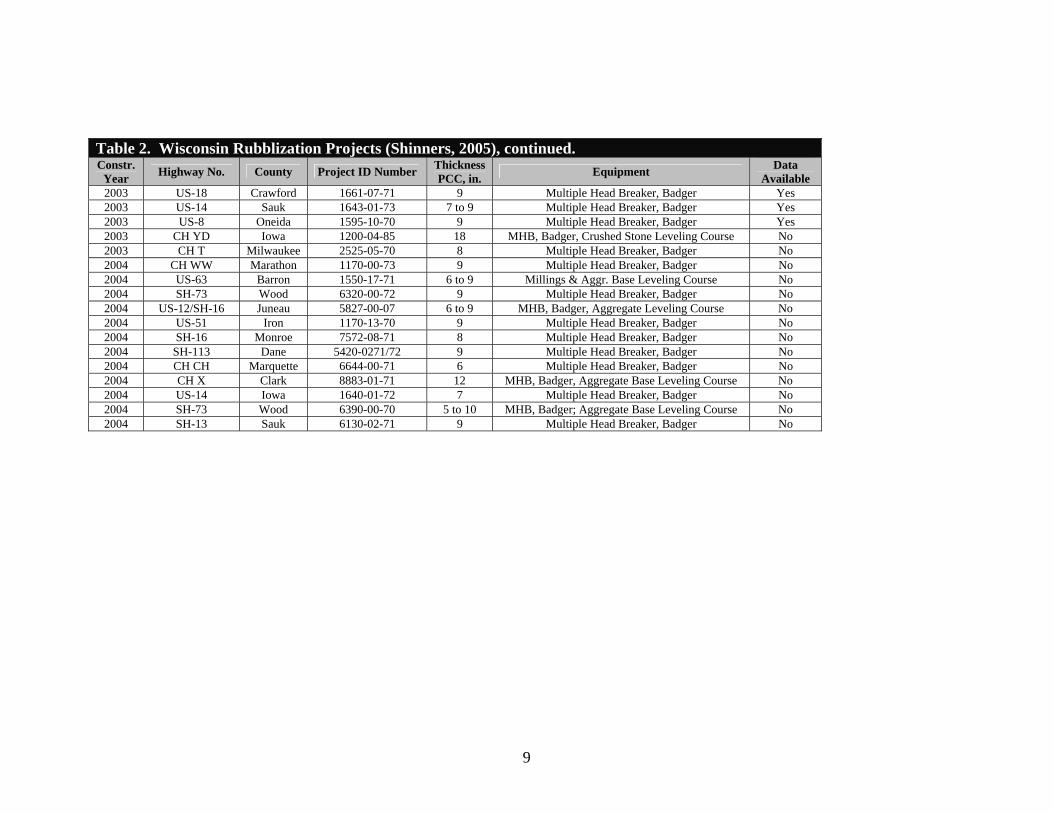
Table 2. Wisconsin Rubblization Projects (Shinners, 2005), continued. Constr.
Year Highway No. County Project ID Number Thickness PCC, in. Equipment Data
Available 2003 US-18 Crawford 1661-07-71 9 Multiple Head Breaker, Badger Yes 2003 US-14 Sauk 1643-01-73 7 to 9 Multiple Head Breaker, Badger Yes 2003 US-8 Oneida 1595-10-70 9 Multiple Head Breaker, Badger Yes 2003 CH YD Iowa 1200-04-85 18 MHB, Badger, Crushed Stone Leveling Course No 2003 CH T Milwaukee 2525-05-70 8 Multiple Head Breaker, Badger No 2004 CH WW Marathon 1170-00-73 9 Multiple Head Breaker, Badger No 2004 US-63 Barron 1550-17-71 6 to 9 Millings & Aggr. Base Leveling Course No 2004 SH-73 Wood 6320-00-72 9 Multiple Head Breaker, Badger No 2004 US-12/SH-16 Juneau 5827-00-07 6 to 9 MHB, Badger, Aggregate Leveling Course No 2004 US-51 Iron 1170-13-70 9 Multiple Head Breaker, Badger No 2004 SH-16 Monroe 7572-08-71 8 Multiple Head Breaker, Badger No 2004 SH-113 Dane 5420-0271/72 9 Multiple Head Breaker, Badger No 2004 CH CH Marquette 6644-00-71 6 Multiple Head Breaker, Badger No 2004 CH X Clark 8883-01-71 12 MHB, Badger, Aggregate Base Leveling Course No 2004 US-14 Iowa 1640-01-72 7 Multiple Head Breaker, Badger No 2004 SH-73 Wood 6390-00-70 5 to 10 MHB, Badger; Aggregate Base Leveling Course No 2004 SH-13 Sauk 6130-02-71 9 Multiple Head Breaker, Badger No
9
In an effort to reduce the particle size, additional passes of the resonant frequency breaker were used during construction. These additional passes totally destroyed the top 4-inches of the PCC slab, while having little effect on the lower 4 inches. The total destruction of the upper part of the PCC slab was confirmed through trenches and elastic layer modulus values calculated from deflection basins measured with the falling weight deflectometer (FWD) – both prior to rubblization and after the HMA leveling course had been placed over the rubblized layer. M-E design analyses were utilized to account for this strength reduction and the 7.5-inch HMA overlay thickness was increased by 1 to 2 inches. Well after 10 years of performance, only minor longitudinal cracks had occurred along the project’s entire length.
Michigan DOT has found and reported that some rubblized pavements performed very well, while others have exhibited various levels of distress (cracking, rutting, and raveling). The average service life of these pavements with higher levels of distress was 14 years, even though the design life was 20 years. The underlying causes for the poorer performance (excessive cracking, rutting, and raveling) of some sections were not evident from a preliminary investigation or from cores removed from these sections. A thorough evaluation of these projects was conducted to identify construction and material issues that contributed significantly to the observed failures (Niederquell, et al., 2000).
The investigation included trenching through the rubblized material, performing in-place permeability tests, and FWD tests in an effort to examine the uniformity of the rubblized material, determine the effective depth of the rubblized material, and assess the permeability of that layer. These projects included the use of both the resonant frequency and the multiple head breaker. It was noticed that with the use of the latter, the presence of soft subgrades could cause shear failure of the underlying materials under the weight of the device and the high energy transmitted. This had resulted in very large rubblized pieces, or in the penetration of these pieces into the subgrade. It was also observed that rubblized material exposed in some trenches had very poor drainage. Based on that study, the following lists some of the prime recommendations.
• Pavements with weak subgrades should not be rubblized with a multiple head breaker.
• The speed of the rubblization device should be maintained as slow as possible to ensure the PCC slabs are adequately and uniformly rubblized through all areas of a project.
• Where horizontal or delamination type cracks occur in the slab, the rubblization process will not fracture the entire depth of the PCC slab. Thus, rubblization should not be used on projects with horizontal or delamination type cracks.
• If an existing HMA overlay is not milled or removed prior to rubblization, the energy imparted through the impact hammer will be reduced or lost through the HMA mixture and hinder the further breaking of the PCC slabs.
• All exposed steel should be cut and depressions covered after rubblization. Excessive roller passes will harm, rather than help compaction.
• Surface of the rubblized layer should be rolled to seat the surface particles prior to placing the HMA overlay.
10
• The use of test strips is essential to calibrate the rubblization operation (speed, frequency, height of hammer drop, etc.) for each site.
Another study was sponsored by the Michigan DOT to identify causes for under performing rubblized concrete pavement projects. This study investigated 75 rubblized projects. About 25 percent of these projects exhibited no signs of distress, while about 50 percent exhibited longitudinal and transverse cracks. The longitudinal and transverse cracking observed was reported as the dominant distress exhibited on the rubblized PCC projects. Segregation in the HMA overlay was also found on about 50 percent of those projects with higher levels of cracking. It was hypothesized that the segregation caused most of the premature cracking, but that hypothesis was challenged.
Michigan State University, under the direction of Dr. Gilbert Baladi, completed theoretical simulations of the HMA overlay placed over rubblized PCC slabs using finite element analysis (FEA) to explain this premature cracking. The study found that the level of cracking was attributed to varying HMA thickness caused by surface profile differences of the rubblized slabs – a leveling course had not been included as part of the design-construction process. The study further concluded that the HMA overlay thickness should be greater for constructability reasons, rather than for structural design requirements.
Illinois DOT - 2002 The Illinois DOT was one of the first States to consider rubblization as a rehabilitation strategy, and has been using this technology since 1990. The Illinois DOT has continually monitored and documented both the construction and performance of these rubblized pavements. After about ten years of placing HMA overlays on rubblized PCC slabs, the Illinois DOT conducted a thorough evaluation of these projects to refine their standards and guidelines for designing and constructing rubblized pavements (Heckel, 2002).
The performance evaluation was conducted in 2002 and included projects built between 1990 and 1999. These projects were located between the north and southern ends of the State. A majority of these projects were on major highways and were found to perform better than patching or overlaying intact PCC slabs with various HMA mixtures. Only low severity distresses were observed on rubblized PCC pavements that were in service well beyond their design life. The Illinois DOT found and concluded that rubblization with HMA overlays, when performed under tight construction tolerances, can provide very good performance based on an evaluation of 70 percent of rubblized projects in the State.
The Illinois DOT refined their specifications for rubblization based on this evaluation, and developed guidelines for designers, contractors, and site engineers who oversee construction projects. This information was published in three different documents, which are listed below.
• Guidelines for Rubblizing PCC Pavement and Designing a Bituminous Concrete Overlay – This document provides guidelines for designers to review the existing
11
structure and designing the HMA overlay. The document requires that a thorough evaluation by the Illinois DOT to select rubblization designs for a specific project site.
• Special Provision for Rubblizing PCC Pavement – This document becomes a part of the contract documents and covers all issues related to the construction process, from rubblization to placing and compacting the HMA overlay.
• Construction Memorandum: Rubblizing PCC Pavement and Placing a Bituminous Concrete Overlay – This document is for the Resident Engineer. It covers and refers to the project background, construction sequence, equipment handling, etc.
Indiana DOT - 2003 The Indiana DOT recently undertook the rehabilitation of I-65, a 4-lane divided interstate, in which three rehabilitation strategies were used to evaluate and compare their relative performance (Gulen et al., 2000, 2004). The existing pavement, a 10-inch JRCP on 8-inch sandy subbase, was built in 1968. It was restored in 1985 when the pavement had deteriorated with about 20 and 7 percent cracked slabs in the outer and inner lanes, respectively. The project had an average serviceability of 2.67 in the north and southbound lanes. By 1994, the pavement showed distress levels comparable to those prior to the concrete pavement restoration (CPR) operations in 1985. The Indiana DOT rehabilitated the pavement using three options—a 12 inch unbonded concrete overlay, a 13-inch HMA overlay placed on rubblized JRCP, and a 7.5-inch fiber-reinforced HMA overlay placed on cracked and seated JRCP.
The Indiana DOT conducted a performance evaluation of all sections in 2003. Based on an initial traffic analysis, the highway has carried roughly 2,700 trucks per day with class 9 trucks prominent in the traffic mix. The rubblized section showed slightly higher signs of raveling than the cracked and seated sections. Transverse cracking was observed in both the HMA overlay sections with premature and higher levels of cracking in the crack and seat option. Crack spacings suggest that these cracks are reflective cracks from underlying joints in the JRCP that were not broken or shattered completely. The unbonded JPCP overlay showed the best performance through 2003.
All overlay types have shown good smoothness performance, although the IRI of rubblized section is lower than the other two options. This difference, however, is not statistically significant. Friction remained relatively constant after rehabilitation in the rubblized section, but showed a steady decrease in the PCC overlay section. The excessive raveling in the cracked and seated section showed an improvement in friction over time. The rubblized pavement also showed uniform structural capacity over time relative to the other options based on deflection basins measured over time. The study concluded that rubblization is the preferred rehabilitation treatment over the crack and seat method. The Indiana DOT is continuing a 20-year monitoring period to evaluate the performance of these rehabilitation strategies, and to perform a comprehensive life cycle cost analysis.
12
Nevada DOT -2003 The Nevada DOT sponsored a study to compare the performance and cost-effectiveness of various rehabilitation strategies (Sebaaly et al., 2003). The rehabilitation strategies included cold in place recycling, crumb rubber modified mixtures, HMA overlays over rubblized PCC pavements, Hveem mixtures with PG-graded binders, and special asphalt binders. Performance indicators used in the evaluation were present serviceability index (PSI), rutting, fatigue cracking, thermal cracking, and block cracking. The study’s objectives were to identify technologies that provide the best service in all Nevada climates, and recommend changes to the existing design and construction practices, both from a construction and materials perspective.
The pavement sections used in this evaluation were not common across the technologies and were under service for varying periods of time, traffic, and environments. The two rubblized pavement sections used in the analysis were built over 15 miles in 1995 and 5.5 miles in 1999. The first rubblization project included a 5-inch HMA overlay placed in 1995. The second included a 1.5-inch HMA overlay. Both projects included a 0.75-inch open-graded HMA mixture placed as a wearing surface. The first section has exhibited no rutting through 6 years of service, but some medium severity fatigue cracks were observed in the 6th year of service. The second rubblized section has performed well with no visible signs of distress. The study recommended the continued use of rubblized PCC pavements.
Colorado DOT – 1999 The Colorado DOT introduced the rubblization technology in 1999 on a three mile project along I-76 near Sterling, Colorado. The project was found to cost approximately 40% less per mile than the typical strategy used by the Colorado DOT, and continues to perform very well. Several rubblization projects have been undertaken since that first demonstration project in Colorado.
Kentucky DOT – 1990 The Kentucky DOT has used the rubblization process along with the break/crack and seat method since the mid-1980’s. Kentucky surveyed and tested over 450 lane-miles where these methods had been used to rehabilitate PCC pavements. Of these 450 lane miles, only one segment had exhibited premature reflection cracking. The department conducted a forensic study of that site and found that the PCC slabs had not been properly cracked. From that survey, the Kentucky DOT continues to use the rubblization and break/crack and seat methods to restore ride quality to some of their PCC pavements.
Strategic Highway Research Program, SPS-6 Experiment The Strategic Highway Research Program (SHRP), during the planning of the Long Term Pavement Performance (LTPP) experiments, recognized an increasing interest in rubblizing PCC slabs to reduce the occurrence of reflection cracks in HMA overlays. This repair strategy was included in the LTPP Special Pavement Study (SPS) experiment defined as SPS-6. However, only a few of these SPS-6 projects actually included the rubblization process. Those projects with rubblization test sections included Alabama, Arizona, Illinois, Michigan, Missouri, Oklahoma, and Pennsylvania, which are listed in
13
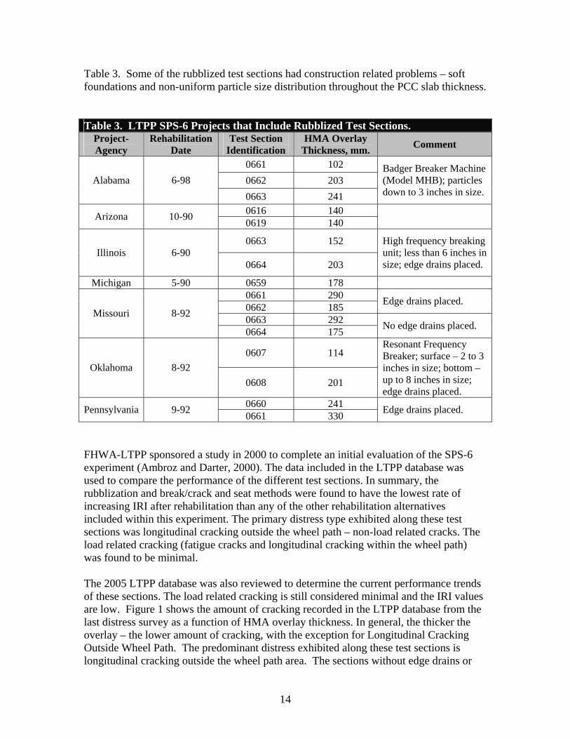
Table 3. Some of the rubblized test sections had construction related problems – soft foundations and non-uniform particle size distribution throughout the PCC slab thickness.
Table 3. LTPP SPS-6 Projects that Include Rubblized Test Sections. Project-Agency
Rehabilitation Date
Test Section Identification
HMA Overlay Thickness, mm. Comment
Alabama 6-98 0661 102 Badger Breaker Machine
(Model MHB); particles down to 3 inches in size.
0662 203 0663 241
Arizona 10-90 0616 140 0619 140
Illinois 6-90 0663 152 High frequency breaking
unit; less than 6 inches in size; edge drains placed. 0664 203
Michigan 5-90 0659 178
Missouri 8-92
0661 290 Edge drains placed.0662 185 0663 292 No edge drains placed.0664 175
Oklahoma 8-92 0607 114
Resonant Frequency Breaker; surface – 2 to 3 inches in size; bottom – up to 8 inches in size; edge drains placed.
0608 201
Pennsylvania 9-92 0660 241 Edge drains placed.0661 330
FHWA-LTPP sponsored a study in 2000 to complete an initial evaluation of the SPS-6 experiment (Ambroz and Darter, 2000). The data included in the LTPP database was used to compare the performance of the different test sections. In summary, the rubblization and break/crack and seat methods were found to have the lowest rate of increasing IRI after rehabilitation than any of the other rehabilitation alternatives included within this experiment. The primary distress type exhibited along these test sections was longitudinal cracking outside the wheel path – non-load related cracks. The load related cracking (fatigue cracks and longitudinal cracking within the wheel path) was found to be minimal.
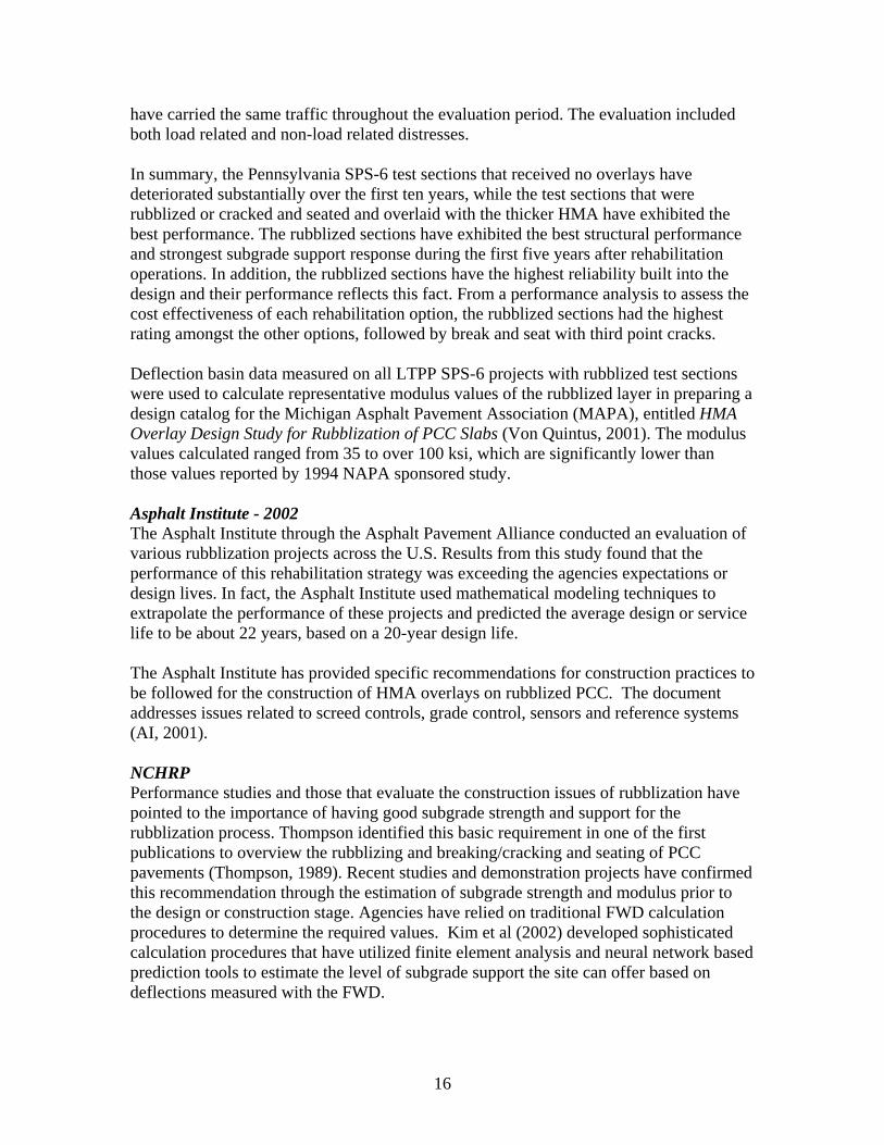
The 2005 LTPP database was also reviewed to determine the current performance trends of these sections. The load related cracking is still considered minimal and the IRI values are low. Figure 1 shows the amount of cracking recorded in the LTPP database from the last distress survey as a function of HMA overlay thickness. In general, the thicker the overlay – the lower amount of cracking, with the exception for Longitudinal Cracking Outside Wheel Path. The predominant distress exhibited along these test sections is longitudinal cracking outside the wheel path area. The sections without edge drains or
14

those with rubblized pieces less than 2 inches in size have the higher levels of cracking. A more complete discussion and data analysis of these sections is included in Chapter 5, along with an analysis of the performance data on the Wisconsin rubblized projects.
700 ide 120
200
300
400
500
600
Long
itudi
nal C
rack
ing
Out
sW
heel
Pat
h, m
.
40
60
80
100
Tran
sver
se C
rack
ing,
m.
100 20
0 0 50 100 150 200 250 300 350 50 100 150 200 250 300 350
Average HMA Overlay Thickness, mm. Average HMA Overlay Thickness, mm.
300 120
250
hin
Wit
100
.q.
m
200
Crac
king
h,
m.
80
150
heel
Pat 60
Fatig
ue C
rack
ing,
s100
dina
l
40
50
Long
ituW
20
0 0 50 100 150 200 250 300 350 50 100 150 200 250 300 350
Average HMA Overlay Thickness, mm. Average HMA Overlay Thickness, mm.
Figure 1 Amount of cracking on the LTPP SPS-6 rubblized test sections.
An evaluation of the performance of several rehabilitation options within the SPS-6 project along I-80 in Pennsylvania was conducted at the end of 10 years of service (Morian et al., 2003). This project was originally built as a jointed concrete pavement, and was included in the SPS-6 experiment in 1988. Rehabilitation operations were completed in 1992. In addition to the eight-core LTPP test sections, three supplemental test sections were built along this project. The three supplemental sections included different pre-overlay treatments and HMA overlays – two of these included rubblized PCC slabs.
The rehabilitation options evaluated by Morian included the minimal and intensive surface preparation with no overlay and a 4-inch HMA overlay section, the saw and seal with a 4-inch overlay section, break and seat with 4 and 8-inch overlay sections, the rubblized sections with 9.5 and 13-inch overlays, and third point sawing in slabs plus crack and seat with 8-inch overlay section. The two rubblized sections included in the study (9.5 and 13-inch HMA overlays) were referred to as LTPP sections 660 and 661, respectively. These two sections were designed for a terminal serviceability of 3.0 for a design life of 10 and 20 years, respectively.
Since 1992, the segment of I-80 has carried approximately 1.4 million equivalent single axle loads (ESALs) per year, with 35 percent truck traffic. All of these SPS-6 sections
15
have carried the same traffic throughout the evaluation period. The evaluation included both load related and non-load related distresses.
In summary, the Pennsylvania SPS-6 test sections that received no overlays have deteriorated substantially over the first ten years, while the test sections that were rubblized or cracked and seated and overlaid with the thicker HMA have exhibited the best performance. The rubblized sections have exhibited the best structural performance and strongest subgrade support response during the first five years after rehabilitation operations. In addition, the rubblized sections have the highest reliability built into the design and their performance reflects this fact. From a performance analysis to assess the cost effectiveness of each rehabilitation option, the rubblized sections had the highest rating amongst the other options, followed by break and seat with third point cracks.
Deflection basin data measured on all LTPP SPS-6 projects with rubblized test sections were used to calculate representative modulus values of the rubblized layer in preparing a design catalog for the Michigan Asphalt Pavement Association (MAPA), entitled HMA Overlay Design Study for Rubblization of PCC Slabs (Von Quintus, 2001). The modulus values calculated ranged from 35 to over 100 ksi, which are significantly lower than those values reported by 1994 NAPA sponsored study.
Asphalt Institute - 2002 The Asphalt Institute through the Asphalt Pavement Alliance conducted an evaluation of various rubblization projects across the U.S. Results from this study found that the performance of this rehabilitation strategy was exceeding the agencies expectations or design lives. In fact, the Asphalt Institute used mathematical modeling techniques to extrapolate the performance of these projects and predicted the average design or service life to be about 22 years, based on a 20-year design life.
The Asphalt Institute has provided specific recommendations for construction practices to be followed for the construction of HMA overlays on rubblized PCC. The document addresses issues related to screed controls, grade control, sensors and reference systems (AI, 2001).
NCHRP Performance studies and those that evaluate the construction issues of rubblization have pointed to the importance of having good subgrade strength and support for the rubblization process. Thompson identified this basic requirement in one of the first publications to overview the rubblizing and breaking/cracking and seating of PCC pavements (Thompson, 1989). Recent studies and demonstration projects have confirmed this recommendation through the estimation of subgrade strength and modulus prior to the design or construction stage. Agencies have relied on traditional FWD calculation procedures to determine the required values. Kim et al (2002) developed sophisticated calculation procedures that have utilized finite element analysis and neural network based prediction tools to estimate the level of subgrade support the site can offer based on deflections measured with the FWD.
16
Another basic requirement identified by Thompson, which has been confirmed through limited field studies and demonstration projects, is the need to place a minimum HMA overlay thickness – regardless of the structural requirements for traffic. The minimum HMA thickness suggested was 4 inches. Many agencies now require a minimum of 4 inches to be placed above any rubblized PCC layer.
Most recently, Arizona State University (ASU) included the use of rubblization as a rehabilitation alternative in developing the M-E Pavement Design Guide under NCHRP 1-37A (ARA, 2004). The default modulus recommended for the rubblized layer is 100,000 psi. Use of 100,000 psi for the rubblized layer will result in HMA overlay thicknesses less than 4 inches for some projects. However, there were no test sections included in the calibration process for this specific repair strategy. The SPS-6 test sections included within the LTPP program had insufficient data to support the calibration process.
Federal Aviation Administration – 2004 Airport agencies and the Federal Aviation Administration (FAA) have now recognized the potential of rubblization in rehabilitating old concrete airfields with the increased practice of rubblization in highways and its adoption by highway agencies (Boyer et al., 2004). The FAA recently published new guidelines and specifications for rubblizing airfield pavements as it foresees major rehabilitation needs for PCC airfield slabs that have such low condition ratings that restoring them into service is beyond the scope of traditional CPR techniques.
An ERDC study utilized information from previous highway and airfield projects, to establish criteria and procedures for economical rehabilitation techniques that will avoid costly premature failures of critical airfield pavement facilities. Some of the sites investigated by ERDC were:
1. I-10 Highway Rehabilitation Project, Louisiana DOT: a. 7-mile rubblization project. b. Equipment used: Resonant Machine Breaker (RMI). c. Pavement structure: new 250-mm (10-in) HMA overlay, 230-mm (9-in) PCC
layer, sandy soil with shells subgrade. d. RMI was using their loading device to measure in-place bulk modulus of the
rubblized layer along this project (refer to Chapter 4). 2. I-65 Highway Rehabilitation Project, Montgomery, Alabama DOT:
a. Equipment used: Multi-Head Hammer Breaker, Antigo Construction Inc. b. Pavement structure: new 280-mm (11-in) HMA overlay, 250-mm (10-in) PCC
layer, subgrade unknown. c. Alabama DOT requires tests pits to be excavated every 305 m (1,000 ft) to verify
fracture particle size distribution.
Engineering Brief (EB) No. 66, Rubblized Portland Cement Concrete Base Course, published by the FAA in April 2004, provides guidance and specifications for rubblization of existing PCC pavements. This document serves as an interim guidance for use in airfield
17
rehabilitation, and information assimilated from industry representatives and the Air Force Civil Engineering Support Agency (AFCESA) formed the basis of this EB. This interim document is being updated, but will not be available until 2007.
As with highway pavements, rubblization is most beneficial for the rehabilitation of PCC pavements with excessive cracking, faulting or rocking slabs. For efficient rubblization, the existing pavement needs to be supported by a strong subbase or subgrade of sufficient quality. Moisture problems, soft spots, voids underneath the slab, or horizontal cracking issues should be addressed prior to rubblization for good results.
FAA recommends the use of traditional overlay design procedures included in Advisory Circular 150/5320-6D to determine the thickness of the HMA overlay on the rubblized PCC layer. A minimum thickness of 4-inches for the HMA surface layer is specified for pavements that are designed to carry aircrafts with gross loads less than 30,000 lb., while 5 or more inches are required for pavement designed for gross loads greater than 30,000 lbs.
FAA treats the rubblized layer as the structural equivalent to a high-quality aggregate base course. For flexible pavement design, a California Bearing Ratio (CBR) of 100 percent is assigned to the rubblization PCC layer, while for rigid pavement design a modulus of subgrade reaction (k) value of 500 pci is used for that layer. These CBR and k assumptions are based on the highest possible values for a cement-stabilized base course. When test results are unavailable for strength parameters, it is assumed that the rubblized material will perform equal to or better than FAA standard Item P-209. Currently, the Department of Defense (DOD) is designing the HMA as a structural layer by assuming a CBR of 100 for the rubblized layer. Alternatively, an elastic modulus of 1034 MPa (150,000 psi) is used in the elastic layer design procedure.
Strength properties of the rubblized layer can be best determined using nondestructive techniques. This value, however, is unavailable prior to construction so the Asphalt Institute’s recommendation in MS-17 manual is considered. In selecting the design modulus for the rubblized layer, the recommended calculation is given below.
DesignModulus = AverageModulus −1.645* SD
Where: SD is the standard deviation.
2.5 Costs of Rubblization Process
With rubblization, the fractured layer is incorporated as a high-quality aggregate base that can be left in place. The rubblize for overlay and break for removal processes require about the same amount of time; however, when the rubblization process is complete, the pavement can be overlaid immediately without having to remove the pavement, make grade preparations, crush the removed material, or replace the underlying layers for the new pavement construction. Other important factors to consider in a rubblization project are the costs for installation of edge drains, which have often been ignored in pavement
18
design. It is now widely accepted that the use of proper drainage systems can greatly improve pavement performance and durability. Drainage costs will vary by project due to climatic conditions and type of drainage system required.
It is estimated that the cost of rubblizing and overlaying is approximately one-third of the cost of removing the old concrete and reconstructing. A recent study conducted by Ms. Vélez-Vega with the U.S. Army Corp of Engineers presented the costs for conventional break/removal/replacement versus rubblization based on a 19-inch-thick PCC airfield pavement (Velez-Vega, 2005). The cost for conventional break/removal/replacement ranged from $3.30-$6.50 per square yard, while rubblization ranged from $0.95-$4.50 per square yard. The removal cost increases, if the material has to be crushed to transport it to a new area. Other agencies (such as Illinois, Indiana, and Michigan DOT) have reported cost ratios between reconstruction and rubblization of about 3 to 1.
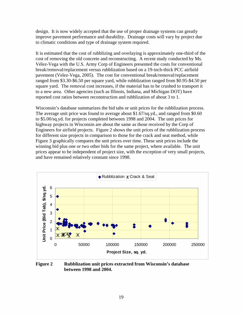
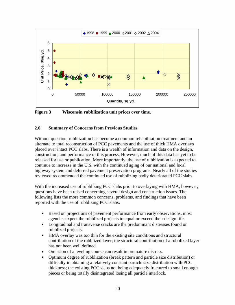
Wisconsin’s database summarizes the bid tabs or unit prices for the rubblization process. The average unit price was found to average about $1.67/sq.yd., and ranged from $0.60 to $5.00/sq.yd. for projects completed between 1998 and 2004. The unit prices for highway projects in Wisconsin are about the same as those received by the Corp of Engineers for airfield projects. Figure 2 shows the unit prices of the rubblization process for different size projects in comparison to those for the crack and seat method, while Figure 3 graphically compares the unit prices over time. These unit prices include the winning bid plus one or two other bids for the same project, where available. The unit prices appear to be independent of project size, with the exception of very small projects, and have remained relatively constant since 1998.
0
1
2
3
4
5
6
0 50000 100000 150000 200000 250000
Project Size, sq. yd.
Unit
Pric
e (B
id T
ab),
$/sq
.yd.
Rubblization Crack & Seat
Figure 2 Rubblization unit prices extracted from Wisconsin’s database between 1998 and 2004.
19
0
1
2
3
4
5
6
0 50000 100000 150000 200000 250000
Quantity, sq.yd.
Uni
t Pri
ce, $
/sq.
yd.
1998 1999 2000 2001 2002 2004
Figure 3 Wisconsin rubblization unit prices over time.
2.6 Summary of Concerns from Previous Studies
Without question, rubblization has become a common rehabilitation treatment and an alternate to total reconstruction of PCC pavements and the use of thick HMA overlays placed over intact PCC slabs. There is a wealth of information and data on the design, construction, and performance of this process. However, much of this data has yet to be released for use or publication. More importantly, the use of rubblization is expected to continue to increase in the U.S. with the continued aging of our national and local highway system and deferred pavement preservation programs. Nearly all of the studies reviewed recommended the continued use of rubblizing badly deteriorated PCC slabs.
With the increased use of rubblizing PCC slabs prior to overlaying with HMA, however, questions have been raised concerning several design and construction issues. The following lists the more common concerns, problems, and findings that have been reported with the use of rubblizing PCC slabs.
• Based on projections of pavement performance from early observations, most agencies expect the rubblized projects to equal or exceed their design life.
• Longitudinal and transverse cracks are the predominant distresses found on rubblized projects.
• HMA overlay was too thin for the existing site conditions and structural contribution of the rubblized layer; the structural contribution of a rubblized layer has not been well defined.
• Omission of a leveling course can result in premature distress. • Optimum degree of rubblization (break pattern and particle size distribution) or
difficulty in obtaining a relatively constant particle size distribution with PCC thickness; the existing PCC slabs not being adequately fractured to small enough pieces or being totally disintegrated losing all particle interlock.
20
• Optimum seating procedures; when the rubblized slab is not properly seated, depressions and longitudinal variations in the surface profile will result in large thickness differences of the HMA overlay and large differences in thickness have been reported to result in premature cracking of the HMA overlay.
• Foundation simply too weak to support the rubblization equipment or soft spots exist along the roadway that are not properly addressed. These soft spots cause depressions from the rubblization and other construction equipment, resulting in premature cracking of the HMA overlay.
• Effect of varying subgrade conditions; soft soils with varying depth to bedrock; high water table in the area; shallow depth to bedrock.
• Drainage needs of the rubblized layer: drainage layer excluded or improperly constructed and maintained over time; saturated soils and rubblized layer not being adequately drained prior to or after construction; many agencies have reported problems with placing a drainage layer as part of the rehabilitation process; inappropriate installation of the drainage systems themselves.
• Delamination or horizontal cracks in thick PCC slabs will restrict the lower portion of the slab from being fractured into acceptable pieces.
• Inadequate debonding of reinforcing steel in JRC and CRC pavements. • Lack of knowledge of the rubblization contractor on the pavement layer
thicknesses. • Inadequate density on the first lift of HMA over the rubblized PCC slabs;
inadequate placement and compaction of the HMA overlay – issue applicable to any HMA overlay.
21
CHAPTER 3 REHABILITATION DESIGN GUIDELINES AND PRACTICES
As noted in Chapters 1 and 2, rubblization is recognized as a cost-effective rehabilitation alternative for rigid pavements that have aged or deteriorated beyond restoration or overlaying (for example, excessive patching, severe joint spalling and deterioration, excessive mid-slab cracking, and slab settlement). Highway agencies have found this process to be very effective in controlling reflective cracks initiating from the existing PCC pavement. A best practices guide for the rehabilitation design using the rubblization method has yet to be prepared, but is needed for day-to-day designs.
Wisconsin has prepared a set of design guidelines for the design of rehabilitation projects using the rubblization technology. These design guidelines are included in their Facilities Development Manual, dated 2002 (Chapter 14, Section 15, Subject 15). The purpose of this chapter is to overview the design practices, parameters, and assumptions that agencies have used in designing HMA overlays for this rehabilitation option of PCC pavements. In summary, there are four key elements of good design practice, each of which is discussed in this chapter and in Wisconsin’s Facilities Development Manual.
1. Detailed evaluation of the existing PCC pavement and foundation support conditions – identifying what is there and the condition of any structures and features along the project limits.
2. Assignment or determination of an equivalent elastic modulus for the rubblized PCC layer, and the uniformity of the rubblized layer.
3. Inclusion of specific design features with the rubblization process – the most important are the use of edge drains and a leveling course.
4. Determining the HMA overlay thickness from a constructability and structural adequacy standpoint.
3.1 Factors to Consider in Evaluating the Rubblization Process for a Particular Project
Both engineering and economic factors need to be considered in selecting any rehabilitation strategy. Among these factors are environmental conditions, subgrade support, PCC condition, design traffic, and life cycle costs.
An evaluation of the existing pavement structure is mandated by the Illinois and Indiana DOT for any rubblization project to assess the feasibility and to ensure the pavement layers and foundation can withstand the loadings and vibrations from construction equipment. This evaluation includes a preliminary soils review, a detailed subsurface investigation that addresses issues related to HMA overlay thickness (if present), subbase condition and thickness (if present), soil support estimates from dynamic cone penetrometer (DCP) and FWD deflection basin tests, soil samples (if needed for further evaluation), survey of existing drainage conditions, shoulder stability to withstand construction equipment, replaced pavement locations, and soil stability during the rubblization process.
22
Similary, soil borings are encouraged by the Ohio DOT in the design phase as early as possible so that a sound judgment can be made on the feasibility of rubblization. Undercutting and backfill are performed as per standard Ohio Guidelines for subgrade treatments. Other agencies require a pavement investigation to estimate the foundation strength of the existing pavement. Experience indicates that rubblization is not recommended for pavements with a foundation modulus less than 100 MPa (15,000 psi). Most agencies calculate the modulus of the foundation layers from deflection basin measurements or DCP tests.
Some agencies give special attention to underground utilities; such as electrical conduits, drainage structures, and other underlying structures. The first step is to ensure that all underground features are located, evaluated, and marked. The rubblization and seating processes must be performed in a manner that will avoid damage to these underground features. In general, reflection and refraction of the stress waves at the interface between the bottom of the PCC and the underlying layers will diminish the energy transmitted into the substructure. The rubblization equipment must be operated in a manner such that the input energy is sufficient to rubblize the full depth of the slab, while not overstressing the underlying layers and structures.
In summary, rubblization is not used for projects with the following features or conditions.
• Projects that have a weak foundation or soft spots – in place soil modulus values less than 15,000 psi.
• Projects that have a high or perched water table, unless a drainage system is installed prior to rubblization for drying out the soils.
• Old-brittle utility lines located near the surface, which do not need to be replaced (generally within 3feet of the PCC layer).
• PCC pavements with low levels of structural distress; such as mid-panel cracks, faulting, corner cracks, etc. If the PCC pavement has remaining life, rubblization may not be a cost-effective solution.
• PCC pavements with potential slope stability problems along the shoulder.
3.2 Material Properties of the Rubblized Layer for Use in Rehabilitation Design
The modulus of a rubblized PCC slab is an important parameter that is needed for determining the thickness of HMA overlays. In fact, this is the most difficult decision for determining the HMA overlay thickness on a rubblized PCC pavement.
Nondestructive deflection basin testing provides significant advantages for selecting a representative design modulus value of the rubblized PCC layer. Unlike traffic, subgrade modulus or other material properties, the layer coefficient and/or modulus for a rubblized PCC slab cannot be tested directly until the rubblization has been completed and the first lift of HMA placed. Thus, previous studies must be used to estimate typical modulus values for the rubblized PCC layer.
23
NAPA recently completed and published a study that provided guidelines for selecting design criteria for the use of HMA overlays to rehabilitate PCC pavements (NAPA, 1994). Various relationships are provided between the AASHTO structural layer coefficient, effective PCC modulus of the cracked slab, and crack spacing for different conditions. For rubblized PCC layers, elastic modulus values of 100 to 150 ksi have been recommended for use in design. The default value recommended for use in the new M-E Pavement Design Guide developed under NCHRP 1-37A is 100 ksi (ARA, 2004). These values are relatively high and will result in thin HMA overlays using M-E based design procedures.
Deflection basin data measured on some of the FHWA LTPP SPS-6 test sections were used to calculate the elastic modulus of rubblized PCC slabs beneath HMA overlays using the MODCOMP, MODULUS, and EVERCALC programs. The resulting values ranged from 35 to over 100 ksi. The higher modulus values are consistent with results from the NAPA study. The particle sizes resulting from the rubblization process on these test sections is unknown and unavailable within the LTPP database. However, this detail is included in the construction reports for some of the SPS-6 projects (refer to table 2). Other agencies ( such as the Arkansas, Michigan, Pennsylvania, and Texas DOT) have used this process on some of their completed projects to select an elastic modulus value representative of the rubblized layer for use in rehabilitation design. The resulting modulus values calculated from deflection basins have been found to be highly variable.
Modulus values of 50, 60, and 70 ksi of the rubblized PCC layer were selected for use in preparing a catalog of rehabilitation designs for MAPA (Von Quintus, 2001). These modulus values were selected to cover the range of values that have been used in previous studies, and were determined from deflection basin testing of HMA overlays placed over rubblized PCC pavements – both from the LTPP SPS-6 experiment and actual construction projects.
In general, the greater extent of rubblization achieved during construction (smaller particle sizes), the lower the modulus of the PCC slab. This hypothesis was checked during the MAPA study referred to in Chapter 2. The representative elastic modulus calculated for an over-rubblized layer, with particle sizes less than 2-inches, was found to be about 35 ksi. This low value suggests that the interlocking of the fractured particles had been lost. The representative elastic modulus calculated for the rubblized layer with much larger particles (6 to 12 inches in size) was found to exceed 70 ksi – suggesting good interlocking between the fractured particles (Von Quintus, 2001).
The modulus of the rubblized PCC pavement can be influenced by the modulus of the supporting subgrade soils. If the rubblized PCC layer functions as a high quality unbound aggregate base material, then that layer will have a limiting modulus value which is dependent on the modulus of the supporting layers. It has been hypothesized that the modulus ratio to be used in design between the rubblized PCC and modulus of the supporting subgrade soils should not exceed a value of 3.5 (Von Quintus, 2001). Larger layer modulus ratios have been found based on the calculation of layer modulus values
24
from deflection basin data. However, field investigations have not been used to confirm the size of the particles in the rubblized layer.
In an ERDC study, several recently rehabilitated military airfields were evaluated to estimate representative modulus values for fractured PCC layers using deflection basin data. Pavement condition surveys were used for a visual examination, while deflection basins measured with a heavy weight deflectometer (HWD) were used for the structural evaluations. Due to limited data from previous rubblized airfield projects, the deflection basin data served as guidance to characterize the rubblization layer for use in design. These results were also used for comparison to typical modulus values of unbound aggregate base course materials. The military airfields included in this study were from the following airfields and facilities.
1. Hunter Army Airfield, Savannah, Georgia (crack and seat PCC slabs): a. East Ramp Taxi lane was rubblized in 2003. b. Equipment used: Guillotine type hammer, and a T8600 Badger Breaker®, Antigo
Construction Inc. c. Pavement structure: 250-mm (10-in) HMA overlay, 11,000 m2 (13,167 yd2) of
200-mm (8-in) cracked PCC, sandy soil subgrade. 2. Selfridge Air National Guard (ANG) Base, Selfridge, Michigan (rubblized PCC
slabs): a. Runway reconstruction in summer 2002. b. Equipment used: Multi-Head Breaker and Guillotine type breaker, Antigo
Construction Inc. c. Pavement structure: 180-mm (7-in) HMA overlay, 115-mm (4.5-in) crushed
concrete base course, rubblized PCC varies from 330 to 530 mm (13 to 21 in), sandy soil subgrade.
The deflection basin data were used to calculate the fractured PCC layer modulus, which are summarized in Table 4. The results show that the average fractured layer modulus can vary from 1030 MPa (15 ksi) to 19,170 MPa (2,780 ksi). Recent deflection data provided by the U.S. Air Force collected along the Niagara Falls Joint Air Reserve Station runway showed a considerable reduction in the modulus of the rubblized layer compared to the modulus values from the Selfridge ANG base and the Hunter Army airfield. Some of the variables in the Niagara Falls runway rubblization project that could have affected the modulus values were a high water table in the area and a shallow depth to bedrock. This was also a 9-inch rubblized PCC layer, and the modulus values ranged from 690 MPa (100 ksi) to 1080 (1,570 ksi), unlike the thickest rubblized PCC layer on the Selfridge ANG base 21-inch runway pavement, which had a modulus value of 8,690 MPa (1,260 ksi). Almost 3 years after the completion of the rubblized project in the Selfridge ANG runway, the pavement is in excellent condition, and the high modulus values indicate a high stiffness value for the rubblized layer. These values are more consistent with the values reported and recommended for use in the NAPA report.
25
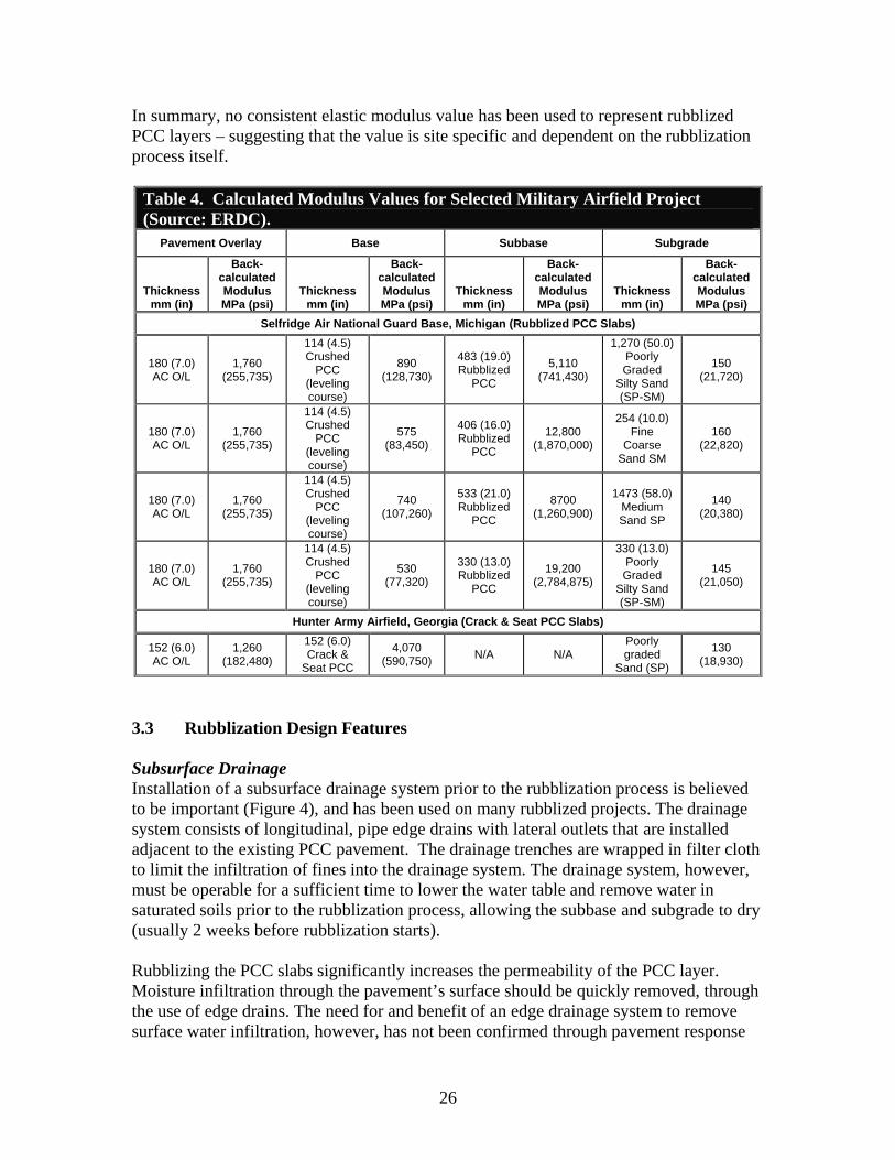
In summary, no consistent elastic modulus value has been used to represent rubblized PCC layers – suggesting that the value is site specific and dependent on the rubblization process itself.
Table 4. Calculated Modulus Values for Selected Military Airfield Project (Source: ERDC).
Pavement Overlay Base Subbase Subgrade
Thickness mm (in)
Back-calculated Modulus MPa (psi)
Thickness mm (in)
Back-calculated Modulus MPa (psi)
Thickness mm (in)
Back-calculated Modulus MPa (psi)
Thickness mm (in)
Back-calculated Modulus MPa (psi)
Selfridge Air National Guard Base, Michigan (Rubblized PCC Slabs)
180 (7.0) AC O/L
1,760 (255,735)
114 (4.5) Crushed
PCC (leveling course)
890 (128,730)
483 (19.0) Rubblized
PCC
5,110 (741,430)
1,270 (50.0) Poorly Graded
Silty Sand (SP-SM)
150 (21,720)
180 (7.0) AC O/L
1,760 (255,735)
114 (4.5) Crushed
PCC (leveling course)
575 (83,450)
406 (16.0) Rubblized
PCC
12,800 (1,870,000)
254 (10.0) Fine
Coarse Sand SM
160 (22,820)
180 (7.0) AC O/L
1,760 (255,735)
114 (4.5) Crushed
PCC (leveling course)
740 (107,260)
533 (21.0) Rubblized
PCC
8700 (1,260,900)
1473 (58.0) Medium Sand SP
140 (20,380)
180 (7.0) AC O/L
1,760 (255,735)
114 (4.5) Crushed
PCC (leveling course)
530 (77,320)
330 (13.0) Rubblized
PCC
19,200 (2,784,875)
330 (13.0) Poorly Graded
Silty Sand (SP-SM)
145 (21,050)
Hunter Army Airfield, Georgia (Crack & Seat PCC Slabs)
152 (6.0) AC O/L
1,260 (182,480)
152 (6.0) Crack &
Seat PCC
4,070 (590,750) N/A N/A
Poorly graded
Sand (SP)
130 (18,930)
3.3 Rubblization Design Features
Subsurface Drainage Installation of a subsurface drainage system prior to the rubblization process is believed to be important (Figure 4), and has been used on many rubblized projects. The drainage system consists of longitudinal, pipe edge drains with lateral outlets that are installed adjacent to the existing PCC pavement. The drainage trenches are wrapped in filter cloth to limit the infiltration of fines into the drainage system. The drainage system, however, must be operable for a sufficient time to lower the water table and remove water in saturated soils prior to the rubblization process, allowing the subbase and subgrade to dry (usually 2 weeks before rubblization starts).
Rubblizing the PCC slabs significantly increases the permeability of the PCC layer. Moisture infiltration through the pavement’s surface should be quickly removed, through the use of edge drains. The need for and benefit of an edge drainage system to remove surface water infiltration, however, has not been confirmed through pavement response
26
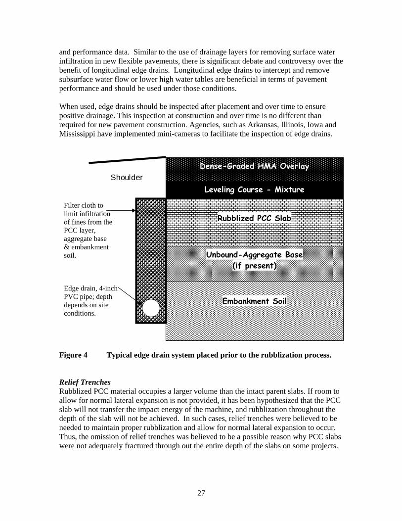
Leveling Course - Mixture
Rubblized PCC Slab
Unbound-Aggregate Base (if present)
Embankment Soil
Dense-Graded HMA Overlay
and performance data. Similar to the use of drainage layers for removing surface water infiltration in new flexible pavements, there is significant debate and controversy over the benefit of longitudinal edge drains. Longitudinal edge drains to intercept and remove subsurface water flow or lower high water tables are beneficial in terms of pavement performance and should be used under those conditions.
When used, edge drains should be inspected after placement and over time to ensure positive drainage. This inspection at construction and over time is no different than required for new pavement construction. Agencies, such as Arkansas, Illinois, Iowa and Mississippi have implemented mini-cameras to facilitate the inspection of edge drains.
Shoulder
Filter cloth to limit infiltration of fines from the PCC layer, aggregate base & embankment soil.
Edge drain, 4-inch PVC pipe; depth depends on site conditions.
Figure 4 Typical edge drain system placed prior to the rubblization process.
Relief Trenches Rubblized PCC material occupies a larger volume than the intact parent slabs. If room to allow for normal lateral expansion is not provided, it has been hypothesized that the PCC slab will not transfer the impact energy of the machine, and rubblization throughout the depth of the slab will not be achieved. In such cases, relief trenches were believed to be needed to maintain proper rubblization and allow for normal lateral expansion to occur. Thus, the omission of relief trenches was believed to be a possible reason why PCC slabs were not adequately fractured through out the entire depth of the slabs on some projects.
27
Relief trenches are usually placed at 9 to 12 meter (30 to 40 foot) intervals. The trench cutter should be capable of trenching the full depth of the PCC slab and be less than 125 mm (5 in) in width. The relief trench should not exceed the nominal depth of the PCC slab, and additional aggregate may be needed to restore grade at the relief trench.
The need for trenching depends largely on the size of the machine being used and the slab thickness. Generally, relief trenches are not necessary when using the multi-head breaking equipment. Smaller resonant machines may require relief trenches more often than larger breakers. In the case of resonant breakers on runways or taxiways wider than 15 m (50 ft), a series of relief trenches parallel to the breaking direction maybe needed. Conversely, highway projects with narrow pavement widths (less than 15 m) typically do not require relief trenches. The requirement for relief trenches and their spacing should be an outcome of any control strip.
No pavement studies, however, have documented the need and effect of relief trenches on the performance of this rehabilitation strategy. In fact, most if not all of the more recent highway rubblization projects have excluded the use of relief trenches.
Leveling Courses The surface of the rubblized PCC layer cannot be bladed with a motor grader. Additional crushed aggregate or a fine-graded, flexible HMA mixture in the form of a leveling course may be required to restore the grade and make profile corrections. A 50- to 100mm (2- to 4-in) leveling course has been used to correct profile differences of the rubblized surface. Crushed concrete, crushed stone, aggregate base, recycled asphalt pavement, and HMA millings are materials that have been used on some of the projects in Wisconsin (refer to Table 2).
Figure 5 shows FWD deflection basins from a rubblized airport pavement before rubblization, after rubblization, and after placing a recycled concrete aggregate (RCA) base course. The figure shows that the RCA leveling increased the deflections, particularly near the loading plate – suggesting a lower modulus material. This lower modulus material is acting as a cushion layer or course. Cushion courses have not been used extensively, because of the increases in pavement surface elevations.
The use of lower modulus materials above the rubblized layer means that a thicker HMA overlay will be needed. In many cases, the use of crushed aggregate base materials as the leveling course can not be used because of clearance or height restrictions at bridges and other overhead structures. As such, HMA leveling courses with specific fracture resistant properties are more beneficial to long term pavement performance. In either case, leveling courses should be accounted for in the structural design. As summarized in Chapter 2, the omission of a leveling course has resulted in premature distress is some cases. The leveling course material should be placed to avoid any segregation problems and properly compacted.
28
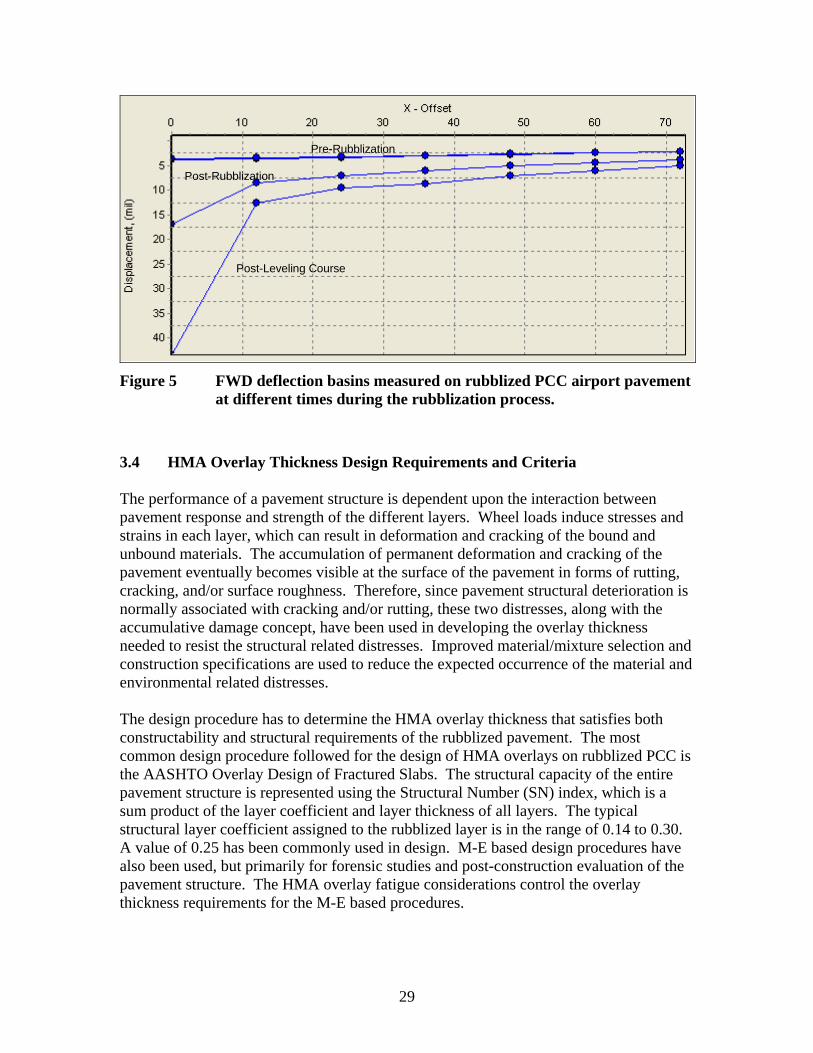
Pre Rubblization
Post-Rubblization
Post-Leveling Course
-Pre-Rubblization
Post-Rubblization
Post-Leveling Course
Figure 5 FWD deflection basins measured on rubblized PCC airport pavement at different times during the rubblization process.
3.4 HMA Overlay Thickness Design Requirements and Criteria
The performance of a pavement structure is dependent upon the interaction between pavement response and strength of the different layers. Wheel loads induce stresses and strains in each layer, which can result in deformation and cracking of the bound and unbound materials. The accumulation of permanent deformation and cracking of the pavement eventually becomes visible at the surface of the pavement in forms of rutting, cracking, and/or surface roughness. Therefore, since pavement structural deterioration is normally associated with cracking and/or rutting, these two distresses, along with the accumulative damage concept, have been used in developing the overlay thickness needed to resist the structural related distresses. Improved material/mixture selection and construction specifications are used to reduce the expected occurrence of the material and environmental related distresses.
The design procedure has to determine the HMA overlay thickness that satisfies both constructability and structural requirements of the rubblized pavement. The most common design procedure followed for the design of HMA overlays on rubblized PCC is the AASHTO Overlay Design of Fractured Slabs. The structural capacity of the entire pavement structure is represented using the Structural Number (SN) index, which is a sum product of the layer coefficient and layer thickness of all layers. The typical structural layer coefficient assigned to the rubblized layer is in the range of 0.14 to 0.30. A value of 0.25 has been commonly used in design. M-E based design procedures have also been used, but primarily for forensic studies and post-construction evaluation of the pavement structure. The HMA overlay fatigue considerations control the overlay thickness requirements for the M-E based procedures.
29
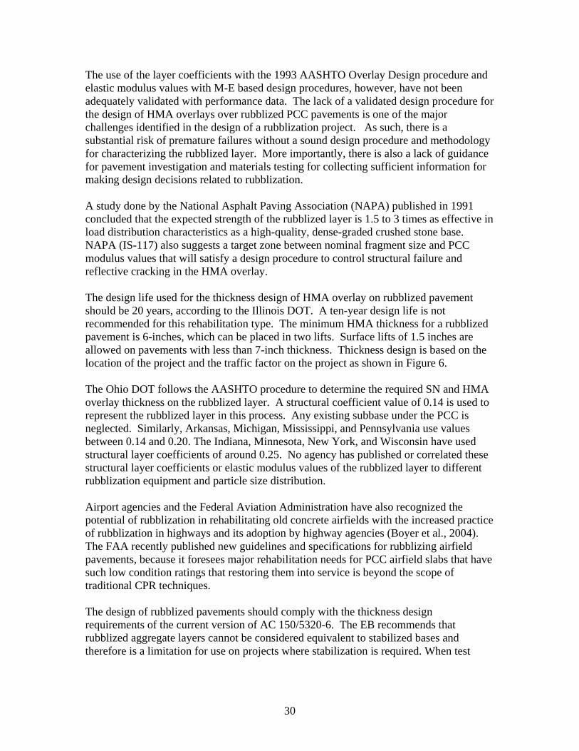
The use of the layer coefficients with the 1993 AASHTO Overlay Design procedure and elastic modulus values with M-E based design procedures, however, have not been adequately validated with performance data. The lack of a validated design procedure for the design of HMA overlays over rubblized PCC pavements is one of the major challenges identified in the design of a rubblization project. As such, there is a substantial risk of premature failures without a sound design procedure and methodology for characterizing the rubblized layer. More importantly, there is also a lack of guidance for pavement investigation and materials testing for collecting sufficient information for making design decisions related to rubblization.
A study done by the National Asphalt Paving Association (NAPA) published in 1991 concluded that the expected strength of the rubblized layer is 1.5 to 3 times as effective in load distribution characteristics as a high-quality, dense-graded crushed stone base. NAPA (IS-117) also suggests a target zone between nominal fragment size and PCC modulus values that will satisfy a design procedure to control structural failure and reflective cracking in the HMA overlay.
The design life used for the thickness design of HMA overlay on rubblized pavement should be 20 years, according to the Illinois DOT. A ten-year design life is not recommended for this rehabilitation type. The minimum HMA thickness for a rubblized pavement is 6-inches, which can be placed in two lifts. Surface lifts of 1.5 inches are allowed on pavements with less than 7-inch thickness. Thickness design is based on the location of the project and the traffic factor on the project as shown in Figure 6.
The Ohio DOT follows the AASHTO procedure to determine the required SN and HMA overlay thickness on the rubblized layer. A structural coefficient value of 0.14 is used to represent the rubblized layer in this process. Any existing subbase under the PCC is neglected. Similarly, Arkansas, Michigan, Mississippi, and Pennsylvania use values between 0.14 and 0.20. The Indiana, Minnesota, New York, and Wisconsin have used structural layer coefficients of around 0.25. No agency has published or correlated these structural layer coefficients or elastic modulus values of the rubblized layer to different rubblization equipment and particle size distribution.
Airport agencies and the Federal Aviation Administration have also recognized the potential of rubblization in rehabilitating old concrete airfields with the increased practice of rubblization in highways and its adoption by highway agencies (Boyer et al., 2004). The FAA recently published new guidelines and specifications for rubblizing airfield pavements, because it foresees major rehabilitation needs for PCC airfield slabs that have such low condition ratings that restoring them into service is beyond the scope of traditional CPR techniques.
The design of rubblized pavements should comply with the thickness design requirements of the current version of AC 150/5320-6. The EB recommends that rubblized aggregate layers cannot be considered equivalent to stabilized bases and therefore is a limitation for use on projects where stabilization is required. When test
30
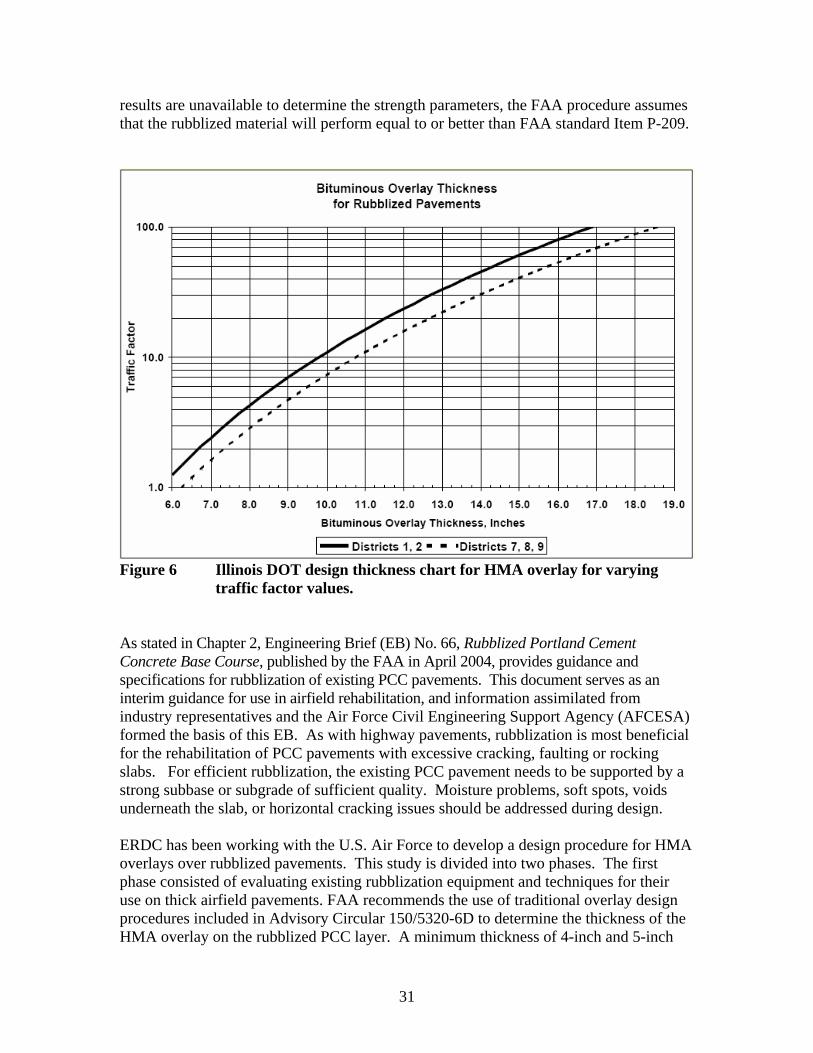
results are unavailable to determine the strength parameters, the FAA procedure assumes that the rubblized material will perform equal to or better than FAA standard Item P-209.
Figure 6 Illinois DOT design thickness chart for HMA overlay for varying traffic factor values.
As stated in Chapter 2, Engineering Brief (EB) No. 66, Rubblized Portland Cement Concrete Base Course, published by the FAA in April 2004, provides guidance and specifications for rubblization of existing PCC pavements. This document serves as an interim guidance for use in airfield rehabilitation, and information assimilated from industry representatives and the Air Force Civil Engineering Support Agency (AFCESA) formed the basis of this EB. As with highway pavements, rubblization is most beneficial for the rehabilitation of PCC pavements with excessive cracking, faulting or rocking slabs. For efficient rubblization, the existing PCC pavement needs to be supported by a strong subbase or subgrade of sufficient quality. Moisture problems, soft spots, voids underneath the slab, or horizontal cracking issues should be addressed during design.
ERDC has been working with the U.S. Air Force to develop a design procedure for HMA overlays over rubblized pavements. This study is divided into two phases. The first phase consisted of evaluating existing rubblization equipment and techniques for their use on thick airfield pavements. FAA recommends the use of traditional overlay design procedures included in Advisory Circular 150/5320-6D to determine the thickness of the HMA overlay on the rubblized PCC layer. A minimum thickness of 4-inch and 5-inch
31

for the HMA surface layer is specified for pavements that are designed to carry aircrafts with gross loads less than and greater than 30,000 lb., respectively.
32

CHAPTER 4 CONSTRUCTION PRACTICES AND SPECIFICATIONS
Since rubblization is a relatively new rehabilitation strategy, State agencies have been periodically refining and updating their specifications for rubblization based on construction problems and limited performance data. Michigan DOT was one of the first agencies to develop a specification for concrete pavement rubblization and several States used this specification to build their State-specific requirements for rubblization. As such, many of the equipment and construction requirements are similar.
Some highway agencies have revised their procedures and specifications to address constructability issues (such as equipment type, crushing operations for different site conditions, etc.) to ensure good performance of the rubblized pavements. Most of these construction issues can be grouped into two main factors: the ability to accurately assess the conditions under the concrete (presented in Chapter 3) and the ability to achieve uniformity of the rubblized layer. The design-related issues that account for achieving minimum material properties used to determine the HMA overlay thickness were summarized in Chapter 3. The construction specifications and practices of State and other agencies practicing rubblization techniques in concrete pavement rehabilitation are summarized in this chapter.
4.1 Equipment Requirements and Operation
The type of equipment for rubblization should be a pavement breaker machine that will deliver adequate energy to rubblize the full depth of the slab and break all existing slab action. The average thickness for a typical highway pavement varies from 6 to 12 inches, while airport pavement thicknesses can range from 15 to 26 inches. The equipment must transfer the energy entirely into the pavement to ensure proper breaking of the PCC slabs.
The two major contractors performing rubblization in the U.S. are RMI (the resonant breaker machine) and Antigo Construction Inc. (multi-head breaker and a guillotine-type breaker). Figure 7 shows the resonant frequency breaker used for rubblizing PCC slabs, while Figure 8 shows the multiple drop hammer. All references to a resonant frequency breaker imply a self-contained, self-propelled resonant frequency breaking unit. Likewise all references to a multiple head breaker imply a self-contained, self-propelled multiple-head impact hammer.
The devices allowed for use in rubblization by the Michigan DOT can be a resonant frequency breaker capable of producing low amplitude 2000 pound (8900 N) force blows at a rate of not less than 44 cycles per second, or a multiple head breaker. When used, the multiple head breaker must have the following features:
• Ability to lift and fall in an independent, adjustable, random sequence with variable force of impact.
• Capability to provide a breaking width of 4-14 feet.
33
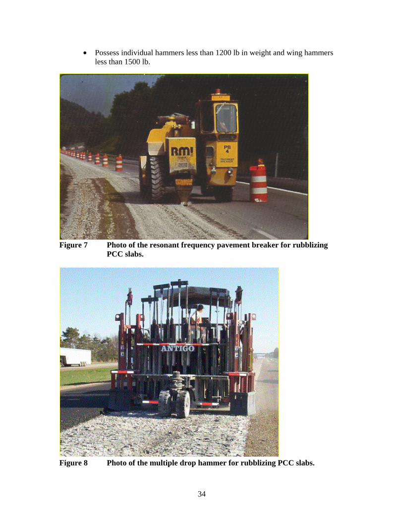
• Possess individual hammers less than 1200 lb in weight and wing hammers less than 1500 lb.
Figure 7 Photo of the resonant frequency pavement breaker for rubblizing PCC slabs.
Figure 8 Photo of the multiple drop hammer for rubblizing PCC slabs.
34
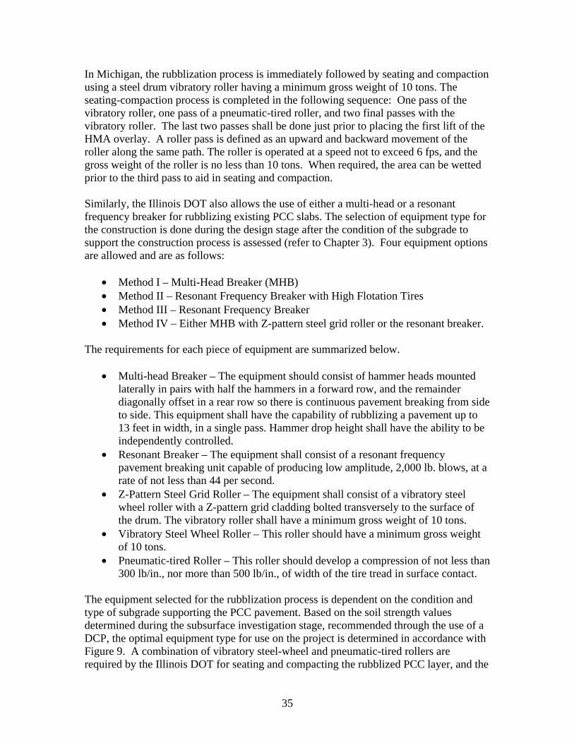
In Michigan, the rubblization process is immediately followed by seating and compaction using a steel drum vibratory roller having a minimum gross weight of 10 tons. The seating-compaction process is completed in the following sequence: One pass of the vibratory roller, one pass of a pneumatic-tired roller, and two final passes with the vibratory roller. The last two passes shall be done just prior to placing the first lift of the HMA overlay. A roller pass is defined as an upward and backward movement of the roller along the same path. The roller is operated at a speed not to exceed 6 fps, and the gross weight of the roller is no less than 10 tons. When required, the area can be wetted prior to the third pass to aid in seating and compaction.
Similarly, the Illinois DOT also allows the use of either a multi-head or a resonant frequency breaker for rubblizing existing PCC slabs. The selection of equipment type for the construction is done during the design stage after the condition of the subgrade to support the construction process is assessed (refer to Chapter 3). Four equipment options are allowed and are as follows:
• Method I – Multi-Head Breaker (MHB) • Method II – Resonant Frequency Breaker with High Flotation Tires • Method III – Resonant Frequency Breaker • Method IV – Either MHB with Z-pattern steel grid roller or the resonant breaker.
The requirements for each piece of equipment are summarized below.
• Multi-head Breaker – The equipment should consist of hammer heads mounted laterally in pairs with half the hammers in a forward row, and the remainder diagonally offset in a rear row so there is continuous pavement breaking from side to side. This equipment shall have the capability of rubblizing a pavement up to 13 feet in width, in a single pass. Hammer drop height shall have the ability to be independently controlled.
• Resonant Breaker – The equipment shall consist of a resonant frequency pavement breaking unit capable of producing low amplitude, 2,000 lb. blows, at a rate of not less than 44 per second.
• Z-Pattern Steel Grid Roller – The equipment shall consist of a vibratory steel wheel roller with a Z-pattern grid cladding bolted transversely to the surface of the drum. The vibratory roller shall have a minimum gross weight of 10 tons.
• Vibratory Steel Wheel Roller – This roller should have a minimum gross weight of 10 tons.
• Pneumatic-tired Roller – This roller should develop a compression of not less than 300 lb/in., nor more than 500 lb/in., of width of the tire tread in surface contact.
The equipment selected for the rubblization process is dependent on the condition and type of subgrade supporting the PCC pavement. Based on the soil strength values determined during the subsurface investigation stage, recommended through the use of a DCP, the optimal equipment type for use on the project is determined in accordance with Figure 9. A combination of vibratory steel-wheel and pneumatic-tired rollers are required by the Illinois DOT for seating and compacting the rubblized PCC layer, and the
35
rubblized PCC layer is primed immediately following the final two passes of the rolling operation. When the multiple headed impact hammer is used, a Z-pattern grid cladding bolted to the surface of the drum of the vibratory roller is used at least for the initial two passes of the seating and compaction operation.
Figure 9 Graphical illustration of the selection of rubblization equipment type, as specified by the Illinois DOT.
The Ohio DOT also allows the use of either a resonant frequency breaker capable of producing low amplitude 2000 pound (8900 N) force blows at a rate of not less than 44 cycles per second, or a multiple head breaker. When used, the multiple head breaker must have the following features.
• Ability to rubblize a 12-foot width in single pass. • Breaking head with at least 12 to 16 hammers weighing a total of 1-1.5 kips • Hammers mounted laterally in pairs with one half in the front row and the
other half diagonally at the rear. • Each hammer is attached to a hydraulic lift cylinder that operates as an
independent unit, and develops 2000 to 12,000 foot-pounds of energy depending on the lift height selected.
• Maximum lift height of 60 inches. • Frequency of 30-35 blows per minute.
36
The rubblization process is followed by seating and compaction using a steel drum vibratory roller having a gross weight of at least 10 tons. The roller shall make a minimum of 2 passes up and back, and it should be operated at a speed not to exceed 6 fps.
The Arkansas DOT allows the use of resonant frequency breaker capable of producing low amplitude 2000 pound (8900 N) force blows at a rate of not less than 44 cycles per second, and rollers consisting of a steel drum vibratory roller having a gross weight of 10 tons (9100 kg), operated in the vibratory mode. The breaker is to be operated at amplitudes less than 1 inch to maintain the stability of the underlying layers. The roller shall make a minimum of 3 passes up and back, and it should be operated at a speed not to exceed 6 fps. The contractor requires an approval from the engineer for the use of all other equipment.
The Indiana DOT specifies the use of a resonant frequency breaker capable of producing low amplitude 2000 pound (8900 N) force blows at a rate of not less than 44 cycles per second or a multiple head breaker with the heads directly adjacent to each other and the lift height of each head independently adjustable. The speed of the rubblizing process is adjusted until the size specification is achieved. Additional passes of the equipment can be used as required. The unit should be equipped with a water system to suppress dust generated by the operation.
Vibratory steel-wheeled, and pneumatic tired rollers are specified by the Indiana DOT after rubblization for seating and compaction – prior to placing the HMA overlay. The layer is seated and compacted by two initial passes with a vibratory roller, followed by two passes with the pneumatic roller, followed again by four passes of the vibratory roller in the sequence mentioned. When the multiple headed impact hammer is used, a Z-pattern grid cladding bolted to the surface of the drum of the vibratory roller shall be used at least for the final two passes. The speed of the vibratory roller should be less than 6 fps.
FAA permits the use of either resonant breaker or multi-head breaker equipments for the rubblization process. The specifications for the equipment used on FAA projects are summarized below.
• Resonant Breaker Machine: The machine should be capable of producing low-amplitude (1 inch maximum) blows of 2000 pounds force, and delivering blows to the existing PCC surface at a rate of not less than 44 cycles per second. If necessary, the breaker should be equipped with a screen to protect nearby structures, vehicles or aircraft from flying chips during the fracturing process.
• Resonant Breaker Seating Equipment: A smooth double steel drum vibratory roller with a gross weight of at least 10 tons should be used, and should be operated in the high frequency, low amplitude vibratory mode to seat the rubblized pavement and provide a smoother surface for the HMA overlay.
37
• Multi-Head Breaker Machine: The machine should be capable of rubblizing a minimum width of 13 feet per pass. Pavement-breaking hammers are to be mounted laterally in pairs, with adjustable heights and with half the hammers in a forward row and the remainder diagonally offset in a rear row so there is continuous breakage from side to side. If necessary, the breaker shall be equipped with a screen to protect vehicles from flying chips during the fracturing process.
• Multi-Head Breaker Seating Equipment: A Z-grid Roller with a gross weight of at least 10 tons, will be operated in the vibratory mode, to settle and seat the rubblized pavement, and provide a smooth surface for the HMA overlay. A pneumatic-tire roller with a gross weight of 10 to 25 tons shall be used to further settle and seat the rubblized pavement for slab thickness of 8-12 inches or higher. Finally, a smooth steel drum vibratory roller with a gross weight of at least 10 tons and operated in the vibratory mode is used to settle the rubblized pavement, and provide a smooth surface for the HMA overlay.
For the resonant breaking process, rubblization should start at a free edge or previously broken edge and progress toward the opposite side or longitudinal centerline of the slab. In areas where the HMA overlay will be placed before the rubblization is complete, the rubblization should extent to a minimum of 150 mm (6 in.) beyond the edge of the HMA to provide relief and transition into the next section to be rubblized. All HMA overlays and/or patches must be removed prior to rubblization.
4.2 Rubblization Criteria – Materials Requirements/Specifications
The Michigan DOT requires that all PCC, including concrete patches, should be rubblized and should be debonded from the reinforced steel. The individual pieces of unreinforced concrete have to be smaller than 8 inches, and in reinforced concrete, the pieces above the reinforcement layer have to be between 2 to 5 inches. If verified to be unbonded, the pieces below the reinforced layer can occasionally be above 8 inches in size. Exposed and protruding reinforcement should not be visible. The underlying base and subgrade should not be disturbed by the rubblization process and equipment.
The Arkansas DOT requires that the rubblized pavement should result into pieces ranging from sand size to less than 6 inches in size. Any individual piece should be no greater than 8 inches in any direction. It is also recommended that a majority of rubblized concrete volume shall be nominal 1 to 3 inches. All steel protruding from the rubblized layer is to be cut prior to overlaying.
The Illinois DOT requires that the PCC in the upper half of the existing pavement or above the reinforcing steel in JRCP rubblization should be fractured into pieces such that at least 75 percent of the pieces are no more than 3 inches in size. Below the reinforcing steel or in the lower one-half of the slab, at least 75 percent of the pieces shall no more than 9 inches. No individual piece should be more than 9-inches or 12-inches in the upper and lower half of the pavement respectively. The reinforcing steel should be fully
38
debonded from the PCC slab. Uniformity of the rubblization is maintained through successive passes of the breaker.
The Ohio DOT recommends rubblization only on concrete pavements with steel embedded in the slab, i.e. it is recommended only for rehabilitating existing JRC and CRC pavements. The rubblized particles should be reduced to sizes varying from sand sized to 6 inches maximum in any dimension. A majority of the particles have to remain in the range of 1 to 2 inches and all concrete above the reinforcing steel has to be reduced to 1 to 2 inches. All visible steel above the rubblized surface has to be cut prior to overlay placement.
The Pennsylvania DOT requires that the rubblized particles be reduced to sizes varying from sand sized to 6 inches maximum in any dimension. At least 51 percent of the rubblized material should measure 4 inches or less, and the remainder should measure no more than 8 inches. All visible steel above the rubblized surface has to be cut prior to overlay placement.
The Indiana DOT requires that the rubblized particles be reduced to sizes varying from sand sized to 6 inches maximum in any dimension. At least 51 percent of the rubblized material should measure 1 to 2 inches or less. All concrete above the reinforcement layer should be reduced to a size in the range of 1-2 inches. All visible steel above the rubblized surface has to be cut prior to overlay placement.
The FAA specifies that the existing concrete pavement will be rubblized to result in at least 75% (as determined by visual observation) of the particles being smaller than: 3 inches at surface; 12 inches in the bottom half. The maximum specified particle size should be no greater than 1.25 times the slab thickness. For most airfield applications, the largest particle size desired is 12 to 15 inches. For rubblizing existing Jointed Reinforced Concrete Pavements (JRCP) the reinforcing steel should be substantially debonded from the concrete and left in place, unless protruding above the surface. Concrete pieces below the reinforcing steel shall be reduced to the greatest possible extent, and no individual piece shall exceed 15 inches in any dimension. Due to lack of edge support, concrete pieces below the reinforcing steel up to 15 inches in any dimension will be accepted along the outside edge of the existing PCC pavement, up to 15 inches from the edge.
4.3 Seating and Rolling Requirements
In the seating phase, sufficient rolling equipment should be used to seat the rubblized layer and provide a smooth, stable surface for the HMA overlay. The number of passes needed to achieve proper compaction varies from project-to-project. The number of operations of the different rollers specified by different state agencies was summarized in this chapter under rubblization equipment and operation.
In general, rolling should not be done under wet conditions. The number of passes and type of equipment required depends upon the rubblization equipment. Generally, a pass
39
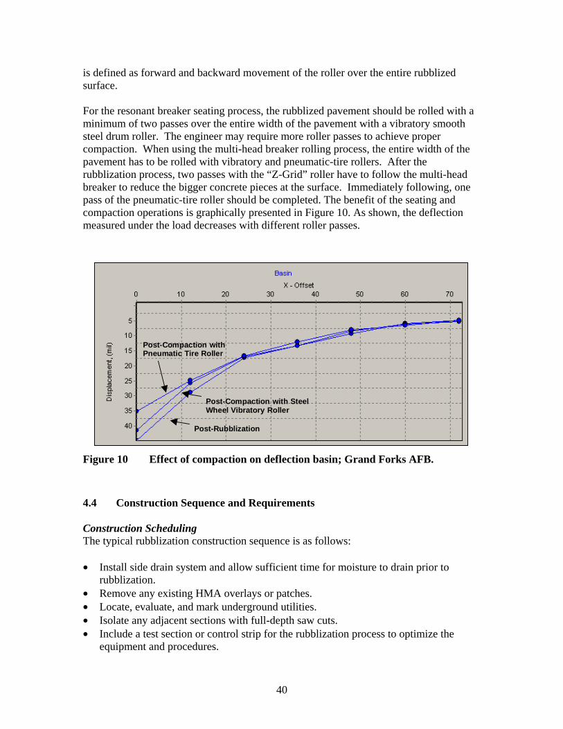
is defined as forward and backward movement of the roller over the entire rubblized surface.
For the resonant breaker seating process, the rubblized pavement should be rolled with a minimum of two passes over the entire width of the pavement with a vibratory smooth steel drum roller. The engineer may require more roller passes to achieve proper compaction. When using the multi-head breaker rolling process, the entire width of the pavement has to be rolled with vibratory and pneumatic-tire rollers. After the rubblization process, two passes with the “Z-Grid” roller have to follow the multi-head breaker to reduce the bigger concrete pieces at the surface. Immediately following, one pass of the pneumatic-tire roller should be completed. The benefit of the seating and compaction operations is graphically presented in Figure 10. As shown, the deflection measured under the load decreases with different roller passes.
Post-Rubblization
Post-Compaction with SteelWheel Vibratory Roller
Post-Compaction withPneumatic Tire Roller
Figure 10 Effect of compaction on deflection basin; Grand Forks AFB.
4.4 Construction Sequence and Requirements
Construction Scheduling The typical rubblization construction sequence is as follows:
• Install side drain system and allow sufficient time for moisture to drain prior to rubblization.
• Remove any existing HMA overlays or patches. • Locate, evaluate, and mark underground utilities. • Isolate any adjacent sections with full-depth saw cuts. • Include a test section or control strip for the rubblization process to optimize the
equipment and procedures.
40
• Rubblize the PCC pavement adjusting equipment and procedures as necessary. • Cut off and remove any exposed steel reinforcement and joint sealing material. • Roll the rubblized PCC. • Remove and replace material in any unstable areas. • Place leveling course. • Place HMA overlay in appropriate lift thicknesses. • Pave transitions to existing pavement surfaces. • Adjust shoulder grades as necessary.
The Illinois DOT specifies the construction process to begin with the installation of drainage elements as required, and getting the surface prepared. After the rubblization is completed, the broken concrete should be compacted in the following sequence:
• Minimum of four passes with Z-pattern steel grid roller (only with the MHB). • Four passes with a vibratory roller. • Two passes with a pneumatic-tired roller.
All protruding steel reinforcement is to be cut prior to placing the overlay. An overlay should be placed on the rubblized pavement at the earliest possible time without delays, and no later than 48 hours.
The Illinois, Indiana, and Ohio DOT also require that the HMA overlay has to be placed on the rubblized concrete within 48 hours after the rubblization process. In the event of rain, the contractor is to delay overlay placement to provide sufficient time for the moisture to drain out or dry. The rubblization process is to be discontinued in the event of rain until the paving operation starts. Additionally, no traffic is allowed to drive the pavement until the first lift of the overlay is placed.
Preparation of Pavement The surface has to be properly prepared for the equipment to transfer energy to accomplish the fracturing process. All agencies require that existing HMA overlays and/or patches be removed prior to rubblization of the PCC slabs. Material transfer devices are specified and used on many HMA overlay projects in Illinois and other agencies. The Illinois DOT requires an evaluation on a project by project basis when material transfer devices are operated on the rubblized layer. Illinois allows partial depth patches to be left in place and rubblized. If these pieces of the PCC slab can not be fragmented by the breaker under or around these patches, they are to be removed and replaced with aggregate fill.
Treatment of Soft Spots and Depressions Proof rolling is recommended in crack/break and seat jobs but not usually recommended or required for rubblization. However, proof rolling would be a good method to avoid particle movement and/or rocking of the fractured pieces. Where soft spots or depressions are identified after the rubblizing process, the Arkansas DOT requires that they be repaired by removing the rubblized pavement, base course and subgrade in accordance with State Specifications and compacting stone backfill and/or aggregate base course as
41
directed by the Engineer. Depressions that are deemed stable by the Engineer shall be corrected by adding aggregate base course and compacting as directed by the Engineer.
The Michigan and Indiana DOT require the subgrade and base layers to be undisturbed. If depressions are found, any depressions more than 1 inch in depth resulting from the rubblizing or rolling process should be packed with filler material and subjected to the same roller passes as the rubblized layer. Depressions are identified using a 10-foot straight edge on the finished surface and locating irregularities.
Similarly, the Ohio DOT requires that depressions more than 1 inch in depth resulting from the rubblizing or rolling process should be packed with filler material and subjected to the same roller passes as the rubblized layer. If the in-situ moisture content is more than 3 percent over the optimum, undercutting and replacement is required in accordance with other Ohio DOT specifications.
The Illinois DOT requires that depressions greater than 2 inches in depth will be filled with replacement material or aggregate fill. This material is also used to reestablish pavement crown when required as approved by the Engineer.
Drainage Systems and Backfill Most state agencies require that edge drains be placed prior to rubblization, as noted in Chapter 3. The Michigan DOT requires all drainage work be completed prior to rubblization. The department requires removal of all pavement layers over utilities or pipes with less than 18 inches of granular material cover, as measured from the bottom of the pavement to the top of the utility or pipe. In addition, the pavement will be removed three feet beyond each edge of the utility or pipe. The removal area is to be backfilled with filler aggregate (maximum 6 inch lift) and thoroughly compacted.
The Illinois DOT requires that the pavement be allowed to drain well before the overlay is placed. Underdrains are recommended, at a minimum, in sag areas of vertical curves. Similarly, the Indiana DOT requires the use of subsurface drainage systems to be installed with any rubblization project. In addition, the FAA suggests that the pavement be provided with adequate drainage and sufficient time provided for moisture to drain out prior to rubblizing.
The Arkansas DOT and other agencies require that stone backfill used in the rubblization process shall be hard, durable, crushed stone aggregate, as manufactured by local quarries, ranging in size from 1½" (40 mm) minimum to 6" (150 mm) maximum. This material, should be uniformly graded with no more than 10 percent by weight passing the 1½” sieve, and will not contain more than 5% by weight of shale, slate, or other deleterious matter. The stone shall be uniformly graded and the amount passing the 1½” (37.5 mm) sieve shall be not more than 10% by weight.
In cases where further backfilling is required to match elevation requirements, the top 4 to 6 inches should consist of granular mechanically crushed natural rock or stone of igneous, sedimentary, and/or metamorphic origin produced from a solid geological
42
formation by quarrying methods. In this material, the fraction passing the number 200 sieve shall not be greater than two-thirds of the fraction passing the number 40 sieve. Further, the fraction passing the number 40 sieve shall have a liquid limit not greater than 25.
The Ohio DOT specifies that the backfill material for use in the rubblization process be identical to the filler material used for conventional construction. The granular material should be maintained at moisture content no more than 2 percent over optimum. The lift thickness should be maintained below 6 inches. In areas where machine placing is impractical or when quantities are too small, hand-placing methods are implemented.
Test Strip and Pit The Arkansas DOT requires that a 4-foot x 4-foot test pit be excavated in the middle of a lane at a location selected by the Engineer to determine if the achieved rubblization process is within specifications and as required for the project. Additional test pits may be required if the Engineer determines that they are necessary. The Illinois DOT also requires the use of two test strips with a minimum area of 10 sq. ft. each to be excavated to examine the quality of rubblization.
The Michigan DOT requires that a test strip be used to verify the adequacy of the rubblizing equipment. During the rubblization process, a test strip at least every 1,500 feet is used to verify that the rubblization criteria are met. This test strip location should not coincide with a joint or crack.
Similarly, the Ohio DOT requires that a test strip be used to determine that the rubblization process is within specifications and as required for the project. Additional test pits may be required if the Engineer determines that they are necessary. A new test strip is suggested when the materials or underlying support conditions change.
The FAA requires that a test strip of approximately 150 feet by 12 feet be used to determine the rubblization process most effective for the site conditions and slab thickness. A 4 sq. ft. test pit is excavated in the middle of the test strip to verify that the specified sizes are achieved, as detailed in the project specifications. Additional test pits may be required to confirm that the PCC pavement is being adequately rubblized.
Initiating or Terminating Rubblization against Existing Pavement The Arkansas DOT requires that rubblizing initiate at a free edge or previously broken edge and progress toward the opposite shoulder or longitudinal centerline of the road. If the roadway is to be overlaid one lane at a time, rubblizing shall extend a minimum of 6 inches beyond the edge of pavement to be overlaid. The department requires that a joint be saw cut full-depth at existing longitudinal joints between the main lanes and ramps and at transverse joints where rubblizing adjoins the pavement that is to remain in place.
In selected areas or locations where an existing concrete pavement or approach slab will remain in place after the rubblization process, the Michigan and Ohio DOT require a saw cut full-depth adjacent to the PCC pavement that will remain in place, and match the
43
elevation with widening or shoulders. When the entire width of the pavement is not rubblized, the rubblization should be extended to at least 18 inches from the center line or boundaries of the lane. Any load transfer device existing is to be cut at existing joints on ramps or mainline.
The Indiana DOT requires that the rubblization begin from pavement edge and proceed to the center. A full depth joint is to be saw cut or load transfer devices shall be severed at an existing joint on ramps or mainline where the rubblizing abuts concrete pavement that is to remain in place.
The FAA requires that shoulder adjustments and/or any pavement widening proposed in the design and construction should be completed up to the elevation of the existing pavement grade prior to beginning the rubblization operations. These areas can be used to support the rubblization machines while the existing PCC pavement is being rubblized.
4.5 Construction Specifications and Quality Assurance
To verify that the equipment is breaking the entire depth of the concrete slab, test pits need to be excavated. As summarized above, every State has its own specifications for the excavation of test pits. Normally, a 1.2-m (4-ft) square test pit is done on a 45.7-m (150-ft) long, 3.7-m (12-ft) wide test strip to verify the fractured slab particle sizes. Airfield rubblization project specifications vary depending on the thickness of the PCC slab. For the rubblization project at the Grand Forks AFB runway, the rubblization specifications limited the PCC pavement particles to be within at least 75 percent (determined by visual inspection) having the largest dimension not exceeding 76 mm (3 inches) at the surface, 229 mm (9 inches) in the top half of the PCC pavement, and 381 mm (15 inches) in the bottom half of the PCC pavement. Dowel bars, tie bars, and reinforcing steel must be debonded from the concrete but can be left in place unless protruding above the surface.
Many typical quality control procedures used for unbound granular bases and subbases are not applicable to rubblized layers. For example, the concepts related to achieving maximum density such as controlling moisture content and measuring dry density do not apply to rubble. Indicators of plasticity such as Atterberg limits and fines content are also not relevant quality indicators. In fact, only particle size distribution (Figure 11), modulus, and strength values have relevancy for rubblized layers.
Current practice for quality control of rubblization involves achieving a desired particle size distribution. In practice, particle size distribution may depend on the existing slab thickness, the presence of reinforcement, the subbase and/or subgrade moisture and strength conditions, the rubblization equipment, and the project’s specifications. Experience has shown that a proper distribution of particle size for airfield pavements will range from sand size to 75 mm (3 in) at the surface and 300 to 380 mm (12 to 15 in) on the bottom part of the rubblized layer. A rule of thumb is that the maximum specified particle size should be no greater than 1.25 times the slab thickness. Typically, the particle size distribution is determined by excavation of test pits in the rubblized material.
44
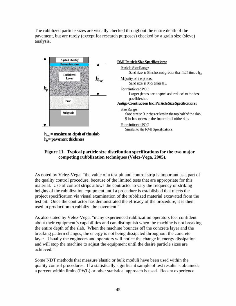
The rubblized particle sizes are visually checked throughout the entire depth of the pavement, but are rarely (except for research purposes) checked by a grain size (sieve) analysis.
RMI Particle Size Specifications:
� Particle Size Range: Sand size to 6 inches not greater than 1.25 times hrub
� Majority of the pieces:hrub Sand size to 0.75 times hrub
hp �For reinforced PCC: Larger pieces are accepted and reduced to the best possible size.
Antigo Construction Inc. Particle SizeSpecifications:
� Size Range: Sand size to 3 inches or less in the top half of the slab.
9 inches orless in the bottom half of the slab.
�For reinforced PCC:
Subgrade
Base
Rubblized Layer
Asphalt Overlay
Permeable zone
Similar to the RMI Specifications hrub= maximum depth of the slab hp = pavement thickness
Figure 11. Typical particle size distribution specifications for the two major competing rubblization techniques (Velez-Vega, 2005).
As noted by Velez-Vega, “the value of a test pit and control strip is important as a part of the quality control procedure, because of the limited tests that are appropriate for this material. Use of control strips allows the contractor to vary the frequency or striking heights of the rubblization equipment until a procedure is established that meets the project specification via visual examination of the rubblized material excavated from the test pit. Once the contractor has demonstrated the efficacy of the procedure, it is then used in production to rubblize the pavement.”
As also stated by Velez-Vega, “many experienced rubblization operators feel confident about their equipment’s capabilities and can distinguish when the machine is not breaking the entire depth of the slab. When the machine bounces off the concrete layer and the breaking pattern changes, the energy is not being dissipated throughout the concrete layer. Usually the engineers and operators will notice the change in energy dissipation and will stop the machine to adjust the equipment until the desire particle sizes are achieved.”
Some NDT methods that measure elastic or bulk moduli have been used within the quality control procedures. If a statistically significant sample of test results is obtained, a percent within limits (PWL) or other statistical approach is used. Recent experience
45
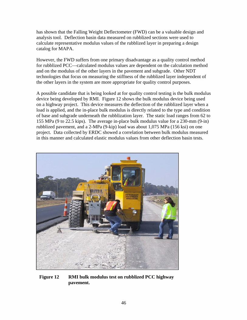
has shown that the Falling Weight Deflectometer (FWD) can be a valuable design and analysis tool. Deflection basin data measured on rubblized sections were used to calculate representative modulus values of the rubblized layer in preparing a design catalog for MAPA.
However, the FWD suffers from one primary disadvantage as a quality control method for rubblized PCC—calculated modulus values are dependent on the calculation method and on the modulus of the other layers in the pavement and subgrade. Other NDT technologies that focus on measuring the stiffness of the rubblized layer independent of the other layers in the system are more appropriate for quality control purposes.
A possible candidate that is being looked at for quality control testing is the bulk modulus device being developed by RMI. Figure 12 shows the bulk modulus device being used on a highway project. This device measures the deflection of the rubblized layer when a load is applied, and the in-place bulk modulus is directly related to the type and condition of base and subgrade underneath the rubblization layer. The static load ranges from 62 to 155 MPa (9 to 22.5 kips). The average in-place bulk modulus value for a 230-mm (9-in) rubblized pavement, and a 2-MPa (9-kip) load was about 1,075 MPa (156 ksi) on one project. Data collected by ERDC showed a correlation between bulk modulus measured in this manner and calculated elastic modulus values from other deflection basin tests.
Figure 12 RMI bulk modulus test on rubblized PCC highway pavement.
46
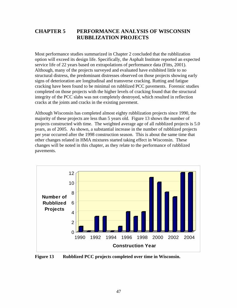
CHAPTER 5 PERFORMANCE ANALYSIS OF WISCONSIN RUBBLIZATION PROJECTS
Most performance studies summarized in Chapter 2 concluded that the rubblization option will exceed its design life. Specifically, the Asphalt Institute reported an expected service life of 22 years based on extrapolations of performance data (Fitts, 2001). Although, many of the projects surveyed and evaluated have exhibited little to no structural distress, the predominant distresses observed on those projects showing early signs of deterioration are longitudinal and transverse cracking. Rutting and fatigue cracking have been found to be minimal on rubblized PCC pavements. Forensic studies completed on those projects with the higher levels of cracking found that the structural integrity of the PCC slabs was not completely destroyed, which resulted in reflection cracks at the joints and cracks in the existing pavement.
Although Wisconsin has completed almost eighty rubblization projects since 1990, the majority of these projects are less than 5 years old. Figure 13 shows the number of projects constructed with time. The weighted average age of all rubblized projects is 5.0 years, as of 2005. As shown, a substantial increase in the number of rubblized projects per year occurred after the 1998 construction season. This is about the same time that other changes related in HMA mixtures started taking effect in Wisconsin. These changes will be noted in this chapter, as they relate to the performance of rubblized pavements.
12
10
8 Number of Rubblized 6 Projects
4
2
0 1990 1992 1994 1996 1998 2000 2002 2004
Construction Year
Figure 13 Rubblized PCC projects completed over time in Wisconsin.
47
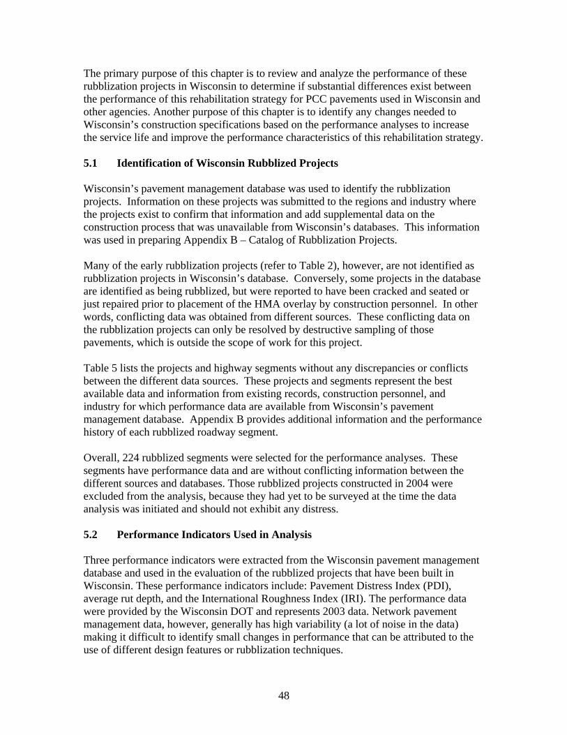
The primary purpose of this chapter is to review and analyze the performance of these rubblization projects in Wisconsin to determine if substantial differences exist between the performance of this rehabilitation strategy for PCC pavements used in Wisconsin and other agencies. Another purpose of this chapter is to identify any changes needed to Wisconsin’s construction specifications based on the performance analyses to increase the service life and improve the performance characteristics of this rehabilitation strategy.
5.1 Identification of Wisconsin Rubblized Projects
Wisconsin’s pavement management database was used to identify the rubblization projects. Information on these projects was submitted to the regions and industry where the projects exist to confirm that information and add supplemental data on the construction process that was unavailable from Wisconsin’s databases. This information was used in preparing Appendix B – Catalog of Rubblization Projects.
Many of the early rubblization projects (refer to Table 2), however, are not identified as rubblization projects in Wisconsin’s database. Conversely, some projects in the database are identified as being rubblized, but were reported to have been cracked and seated or just repaired prior to placement of the HMA overlay by construction personnel. In other words, conflicting data was obtained from different sources. These conflicting data on the rubblization projects can only be resolved by destructive sampling of those pavements, which is outside the scope of work for this project.
Table 5 lists the projects and highway segments without any discrepancies or conflicts between the different data sources. These projects and segments represent the best available data and information from existing records, construction personnel, and industry for which performance data are available from Wisconsin’s pavement management database. Appendix B provides additional information and the performance history of each rubblized roadway segment.
Overall, 224 rubblized segments were selected for the performance analyses. These segments have performance data and are without conflicting information between the different sources and databases. Those rubblized projects constructed in 2004 were excluded from the analysis, because they had yet to be surveyed at the time the data analysis was initiated and should not exhibit any distress.
5.2 Performance Indicators Used in Analysis
Three performance indicators were extracted from the Wisconsin pavement management database and used in the evaluation of the rubblized projects that have been built in Wisconsin. These performance indicators include: Pavement Distress Index (PDI), average rut depth, and the International Roughness Index (IRI). The performance data were provided by the Wisconsin DOT and represents 2003 data. Network pavement management data, however, generally has high variability (a lot of noise in the data) making it difficult to identify small changes in performance that can be attributed to the use of different design features or rubblization techniques.
48

Table 5. Wisonsin Rubblization Projects and Segments Included in the Performance Analysis – 2003 Data. Rubblization
Year Highway Number County Sequential
Number PDI Rut Depth, 1/100 in.
IRI, in./mi.
1992 73 Waushara
94340 27 14 78 94350 28 13 80 94360 13 14 65 94370 19 13 76 94380 68 12 77 94390 43 15 66 94400 43 13 83 94410 19 16 67 94420 34 16 72 94430 60 13 68 94440 32 14 83
1996 16 Monroe 18310 0 13 69 18320 0 13 65
1996 51 Dane 67690 28 7 119 67700 48 5 84 67710 22 5 97
1997 12 Monroe
10340 0 11 59 10350 0 9 59 10360 27 10 53 10370 0 14 49 10380 0 16 42 10390 0 17 47 10400 0 11 42
1998 12, WB Walworth
12670 26 7 77 12680 13 4 72 12690 13 4 60 12700 7 4 55 12710 21 4 69 12720 7 4 59 12730 0 7 90 12740 0 5 59
1998 12, EB Walworth
11850 42 4 63 11860 13 4 57 11870 13 7 45 11880 13 4 34 11890 13 5 58 11900 13 5 63 11910 7 3 62 11920 18 4 85
49

Table 5. Wisonsin Rubblization Projects and Segments Included in the Performance Analysis – 2003 Data, continued. Rubblization
Year Highway Number County Sequential
Number PDI Rut Depth, 1/100 in.
IRI, in./mi.
1998 14 Vernon
16360 7 5 57 16370 26 6 46 16380 7 6 54 16390 7 5 40 16400 38 7 40 16410 38 7 42 16420 7 6 45 16430 7 6 44
1999 13 Adams 12970 20 18 55 12980 0 11 46 12990 13 12 70
1999 39, NB Portage
49050 0 4 50 49060 0 5 43 49070 0 3 55 49080 0 2 41 49090 0 2 27 49100 0 2 35 49110 0 3 54 49120 0 3 43 49130 0 2 49 49140 0 4 54
1999 39, SB Portage
49870 0 3 45 49880 0 2 52 49890 0 2 30 49900 0 3 51 49910 0 4 30 49920 0 3 30 49930 0 4 48 49940 0 5 44 49950 7 4 47 49960 7 4 53 49970 0 4 54
1999 66 Portage 88740 0 6 48 88750 0 6 31 88760 7 6 47
1999* 67; Williams Bay Walworth 89050 32 5 67
2000 14 Richland
16720 0 6 59 16730 0 5 41 16740 0 6 53 16750 0 6 42 16760 0 8 38
1999* 16; Oconomowoc Waukesha 19250 7 13 154
2001 23 Sauk 27330 0 4 64 27340 0 1 46 27350 0 3 37
* - Denotes projects in an urban area.
50
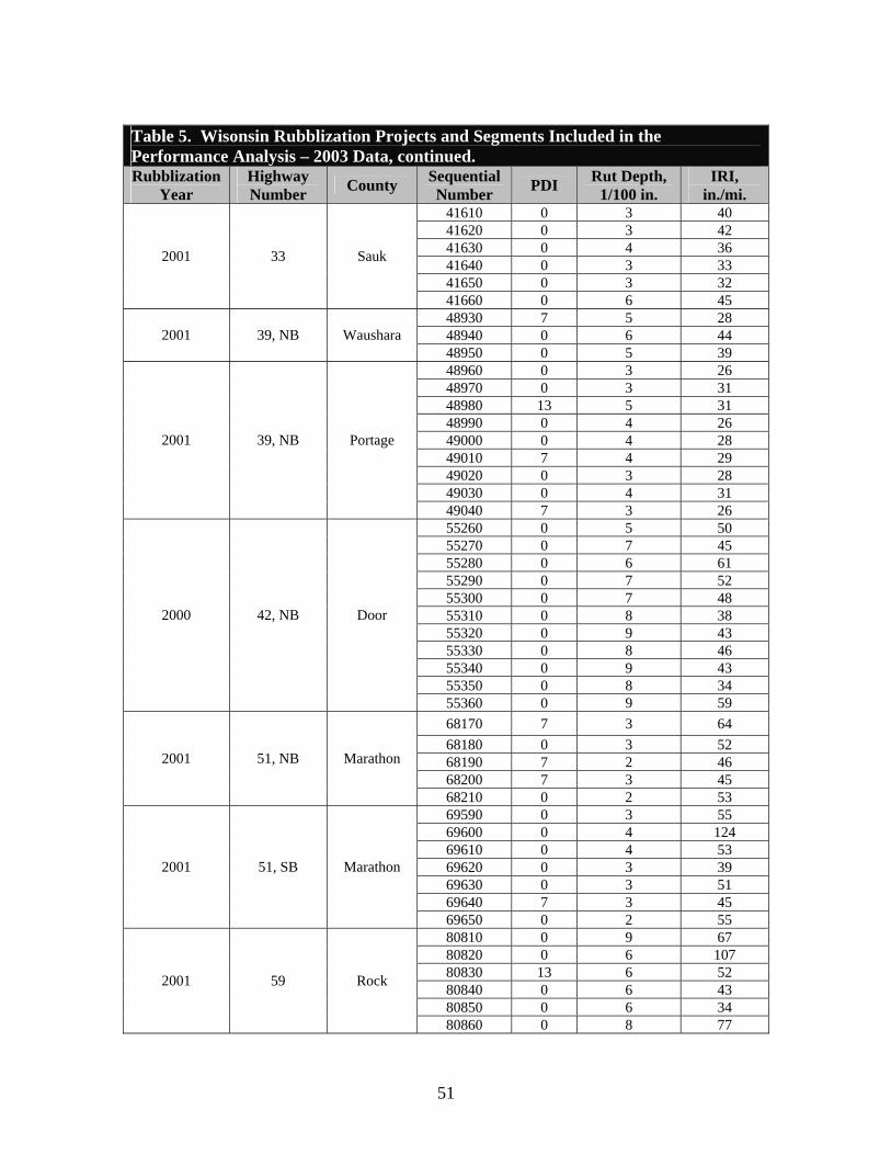
Table 5. Wisonsin Rubblization Projects and Segments Included in the Performance Analysis – 2003 Data, continued. Rubblization
Year Highway Number County Sequential
Number PDI Rut Depth, 1/100 in.
IRI, in./mi.
2001 33 Sauk
41610 0 3 40 41620 0 3 42 41630 0 4 36 41640 0 3 33 41650 0 3 32 41660 0 6 45
2001 39, NB Waushara 48930 7 5 28 48940 0 6 44 48950 0 5 39
2001 39, NB Portage
48960 0 3 26 48970 0 3 31 48980 13 5 31 48990 0 4 26 49000 0 4 28 49010 7 4 29 49020 0 3 28 49030 0 4 31 49040 7 3 26
2000 42, NB Door
55260 0 5 50 55270 0 7 45 55280 0 6 61 55290 0 7 52 55300 0 7 48 55310 0 8 38 55320 0 9 43 55330 0 8 46 55340 0 9 43 55350 0 8 34 55360 0 9 59
2001 51, NB Marathon
68170 7 3 64 68180 0 3 52 68190 7 2 46 68200 7 3 45 68210 0 2 53
2001 51, SB Marathon
69590 0 3 55 69600 0 4 124 69610 0 4 53 69620 0 3 39 69630 0 3 51 69640 7 3 45 69650 0 2 55
2001 59 Rock
80810 0 9 67 80820 0 6 107 80830 13 6 52 80840 0 6 43 80850 0 6 34 80860 0 8 77
51
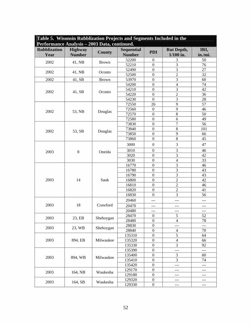
Table 5. Wisonsin Rubblization Projects and Segments Included in the Performance Analysis – 2003 Data, continued. Rubblization
Year Highway Number County Sequential
Number PDI Rut Depth, 1/100 in.
IRI, in./mi.
2002 41, NB Brown 52200 0 3 50 52210 0 3 76
2002 41, NB Oconto 52490 0 3 27 52500 0 2 32
2002 41, SB Brown 53970 0 3 60
2002 41, SB Oconto
54200 0 4 74 54210 0 3 42 54220 0 2 36 54230 0 3 28
2002 53, NB Douglas
72550 26 9 57 72560 0 9 46 72570 0 8 50 72580 0 6 49
2002 53, SB Douglas
73830 0 7 56 73840 0 8 101 73850 0 9 66 73860 0 8 45
2003 8 Oneida
3000 0 3 47 3010 0 3 46 3020 0 3 42 3030 0 4 33
2003 14 Sauk
16770 0 3 46 16780 0 3 43 16790 0 3 43 16800 0 2 42 16810 0 2 46 16820 0 2 41 16830 0 3 56
2003 18 Crawford 20460 --- --- --- 20470 --- --- --- 20480 --- --- ---
2003 23, EB Sheboygan 28470 0 5 52 28480 0 4 78
2003 23, WB Sheboygan 28830 0 --- --- 28840 0 4 70
2003 894, EB Milwaukee 135310 0 5 64 135320 0 4 66 135330 0 3 92
2003 894, WB Milwaukee
135390 0 --- --- 135400 0 3 60 135410 0 3 74 135420 0 --- ---
2003 164, NB Waukesha 129170 0 --- --- 129180 0 --- ---
2003 164, SB Waukesha 129320 0 --- --- 129330 0 --- ---
52
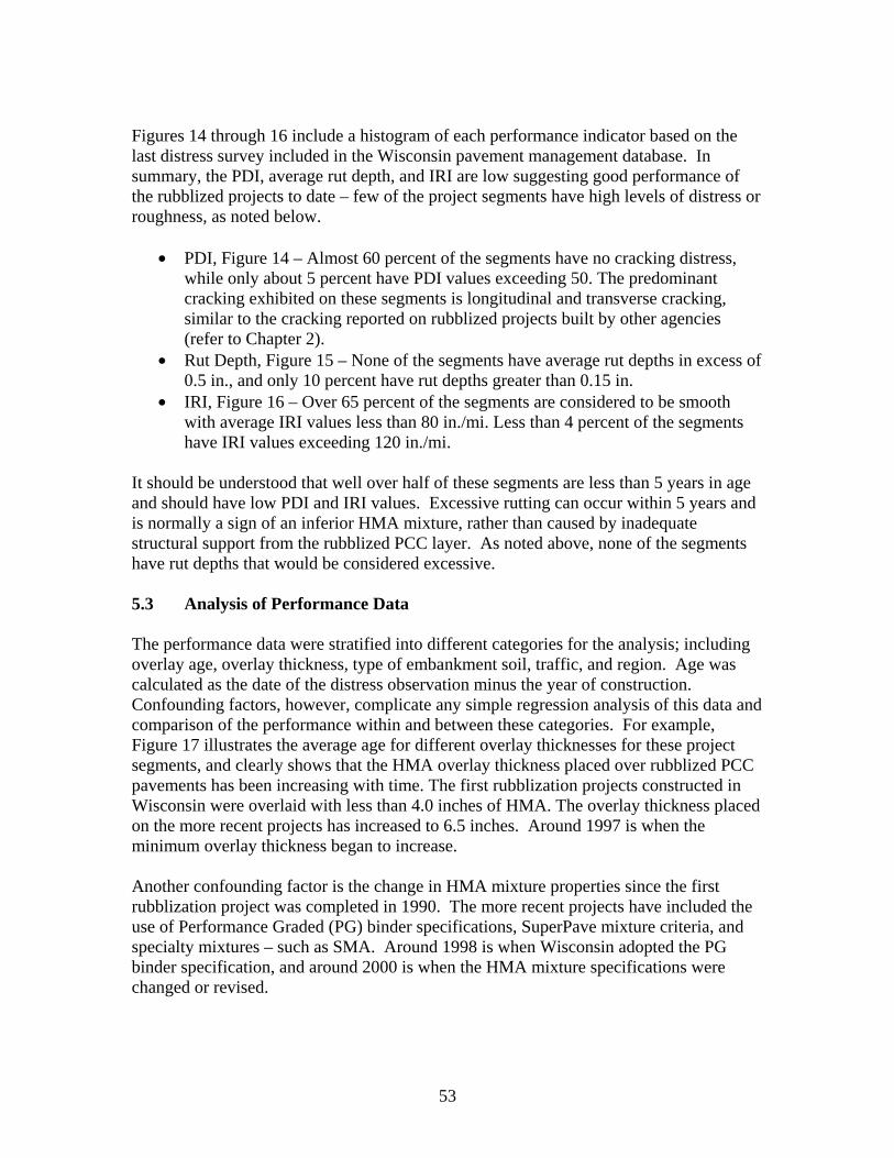
Figures 14 through 16 include a histogram of each performance indicator based on the last distress survey included in the Wisconsin pavement management database. In summary, the PDI, average rut depth, and IRI are low suggesting good performance of the rubblized projects to date – few of the project segments have high levels of distress or roughness, as noted below.
• PDI, Figure 14 – Almost 60 percent of the segments have no cracking distress, while only about 5 percent have PDI values exceeding 50. The predominant cracking exhibited on these segments is longitudinal and transverse cracking, similar to the cracking reported on rubblized projects built by other agencies (refer to Chapter 2).
• Rut Depth, Figure 15 – None of the segments have average rut depths in excess of 0.5 in., and only 10 percent have rut depths greater than 0.15 in.
• IRI, Figure 16 – Over 65 percent of the segments are considered to be smooth with average IRI values less than 80 in./mi. Less than 4 percent of the segments have IRI values exceeding 120 in./mi.
It should be understood that well over half of these segments are less than 5 years in age and should have low PDI and IRI values. Excessive rutting can occur within 5 years and is normally a sign of an inferior HMA mixture, rather than caused by inadequate structural support from the rubblized PCC layer. As noted above, none of the segments have rut depths that would be considered excessive.
5.3 Analysis of Performance Data
The performance data were stratified into different categories for the analysis; including overlay age, overlay thickness, type of embankment soil, traffic, and region. Age was calculated as the date of the distress observation minus the year of construction. Confounding factors, however, complicate any simple regression analysis of this data and comparison of the performance within and between these categories. For example, Figure 17 illustrates the average age for different overlay thicknesses for these project segments, and clearly shows that the HMA overlay thickness placed over rubblized PCC pavements has been increasing with time. The first rubblization projects constructed in Wisconsin were overlaid with less than 4.0 inches of HMA. The overlay thickness placed on the more recent projects has increased to 6.5 inches. Around 1997 is when the minimum overlay thickness began to increase.
Another confounding factor is the change in HMA mixture properties since the first rubblization project was completed in 1990. The more recent projects have included the use of Performance Graded (PG) binder specifications, SuperPave mixture criteria, and specialty mixtures – such as SMA. Around 1998 is when Wisconsin adopted the PG binder specification, and around 2000 is when the HMA mixture specifications were changed or revised.
53
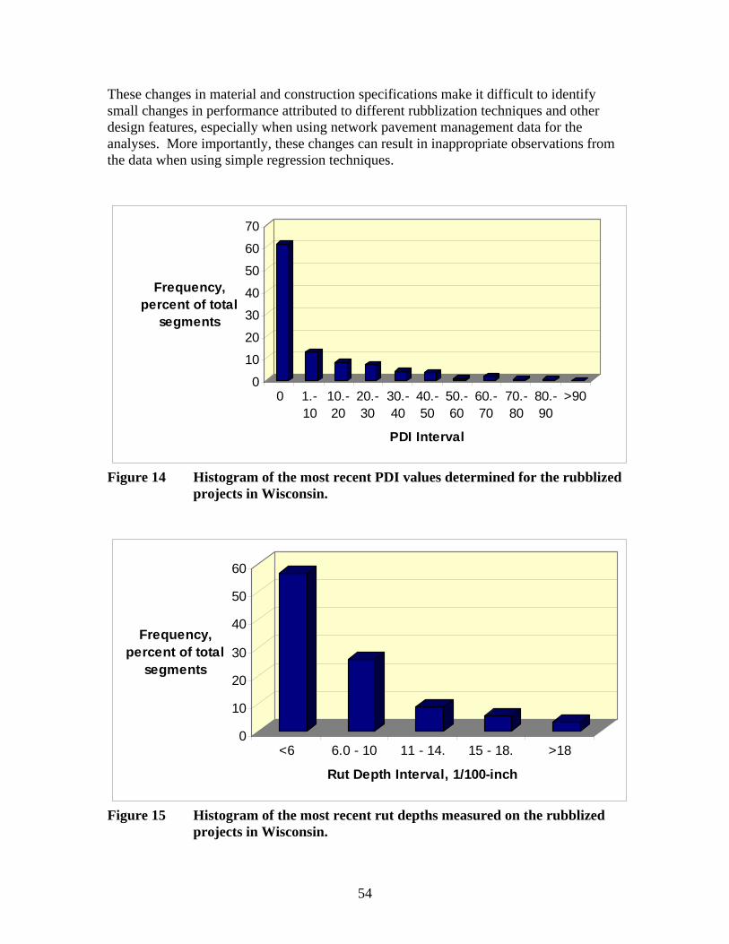
These changes in material and construction specifications make it difficult to identify small changes in performance attributed to different rubblization techniques and other design features, especially when using network pavement management data for the analyses. More importantly, these changes can result in inappropriate observations from the data when using simple regression techniques.
0
10
20
30
40
50
60
70
Frequency, percent of total
segments
0 1.-10
10.-20
20.-30
30.-40
40.-50
50.-60
60.-70
70.-80
80.-90
>90
PDI Interval
Figure 14 Histogram of the most recent PDI values determined for the rubblized projects in Wisconsin.
0
10
20
30
40
50
60
Frequency, percent of total
segments
<6 6.0 - 10 11 - 14. 15 - 18. >18
Rut Depth Interval, 1/100-inch
Figure 15 Histogram of the most recent rut depths measured on the rubblized projects in Wisconsin.
54
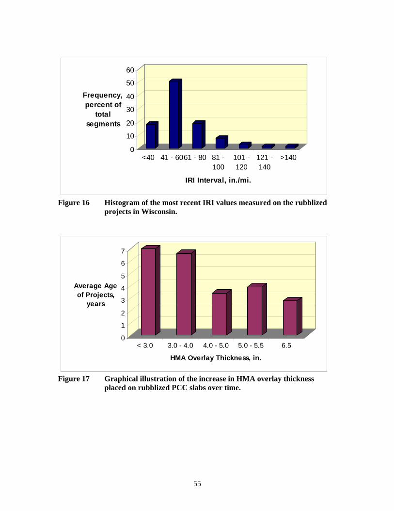
0
10
20
30
40
50
60
Frequency, percent of
total segments
<40 41 - 6061 - 80 81 -100
101 -120
121 -140
>140
IRI Interval, in./mi.
Figure 16 Histogram of the most recent IRI values measured on the rubblized projects in Wisconsin.
0
1
2
3
4
5
6
7
Average Age of Projects,
years
< 3.0 3.0 - 4.0 4.0 - 5.0 5.0 - 5.5 6.5
HMA Overlay Thickness, in.
Figure 17 Graphical illustration of the increase in HMA overlay thickness placed on rubblized PCC slabs over time.
55
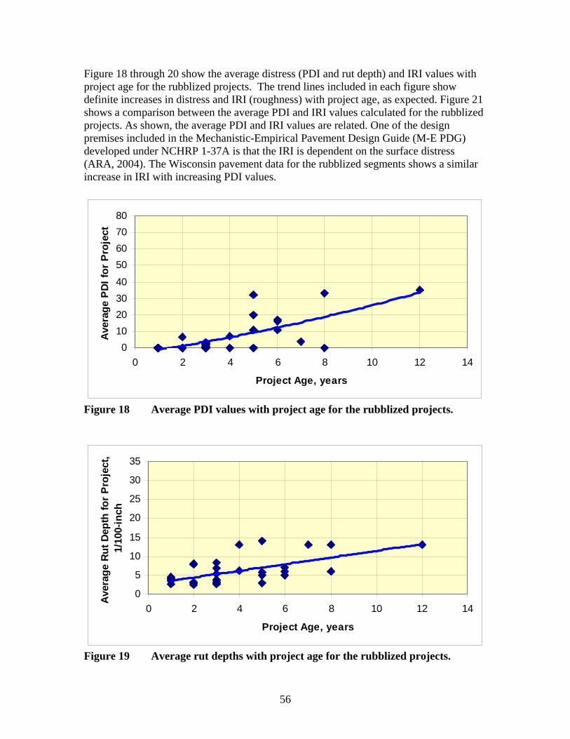
Figure 18 through 20 show the average distress (PDI and rut depth) and IRI values with project age for the rubblized projects. The trend lines included in each figure show definite increases in distress and IRI (roughness) with project age, as expected. Figure 21 shows a comparison between the average PDI and IRI values calculated for the rubblized projects. As shown, the average PDI and IRI values are related. One of the design premises included in the Mechanistic-Empirical Pavement Design Guide (M-E PDG) developed under NCHRP 1-37A is that the IRI is dependent on the surface distress (ARA, 2004). The Wisconsin pavement data for the rubblized segments shows a similar increase in IRI with increasing PDI values.
0 10 20 30 40
50 60 70 80
0 2 4 6 8 10 12 14
Project Age, years
Ave
rage
PD
I for
Pro
ject
Figure 18 Average PDI values with project age for the rubblized projects.
0
5
10
15
20
25
30
35
0 2 4 6 8 10 12 14
Project Age, years
Aver
age
Rut D
epth
for P
roje
ct,
1/10
0-in
ch
Figure 19 Average rut depths with project age for the rubblized projects.
56
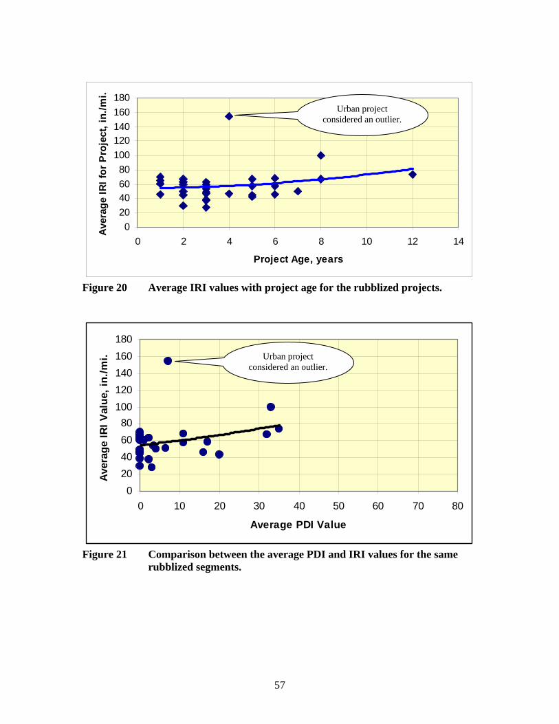
0 20 40 60 80
100 120 140 160 180
0 2 4 6 8 10 12 14
Project Age, years
Aver
age
IRI f
or P
roje
ct, i
n./m
i. Urban project
considered an outlier.
Figure 20 Average IRI values with project age for the rubblized projects.
180
Aver
age
IRI V
alue
, in.
/mi. 160
140 120 100 80 60 40 20 0
Urban project considered an outlier.
0 10 20 30 40 50 60 70
Average PDI Value
Figure 21 Comparison between the average PDI and IRI values for the same rubblized segments.
57
80
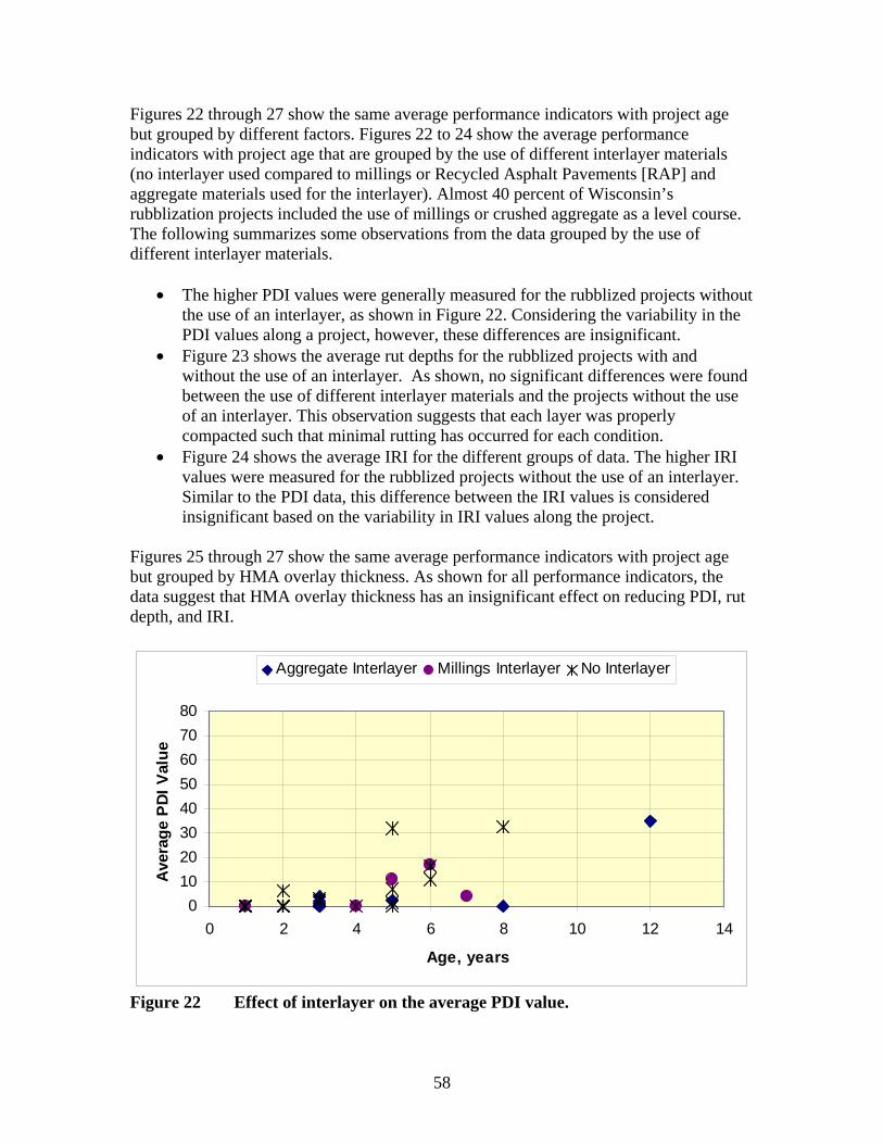
Figures 22 through 27 show the same average performance indicators with project age but grouped by different factors. Figures 22 to 24 show the average performance indicators with project age that are grouped by the use of different interlayer materials (no interlayer used compared to millings or Recycled Asphalt Pavements [RAP] and aggregate materials used for the interlayer). Almost 40 percent of Wisconsin’s rubblization projects included the use of millings or crushed aggregate as a level course. The following summarizes some observations from the data grouped by the use of different interlayer materials.
• The higher PDI values were generally measured for the rubblized projects without the use of an interlayer, as shown in Figure 22. Considering the variability in the PDI values along a project, however, these differences are insignificant.
• Figure 23 shows the average rut depths for the rubblized projects with and without the use of an interlayer. As shown, no significant differences were found between the use of different interlayer materials and the projects without the use of an interlayer. This observation suggests that each layer was properly compacted such that minimal rutting has occurred for each condition.
• Figure 24 shows the average IRI for the different groups of data. The higher IRI values were measured for the rubblized projects without the use of an interlayer. Similar to the PDI data, this difference between the IRI values is considered insignificant based on the variability in IRI values along the project.
Figures 25 through 27 show the same average performance indicators with project age but grouped by HMA overlay thickness. As shown for all performance indicators, the data suggest that HMA overlay thickness has an insignificant effect on reducing PDI, rut depth, and IRI.
0 10 20 30 40 50 60 70 80
0 2 4 6 8 10 12 14
Age, years
Ave
rage
PDI
Val
ue
Aggregate Interlayer Millings Interlayer No Interlayer
Figure 22 Effect of interlayer on the average PDI value.
58
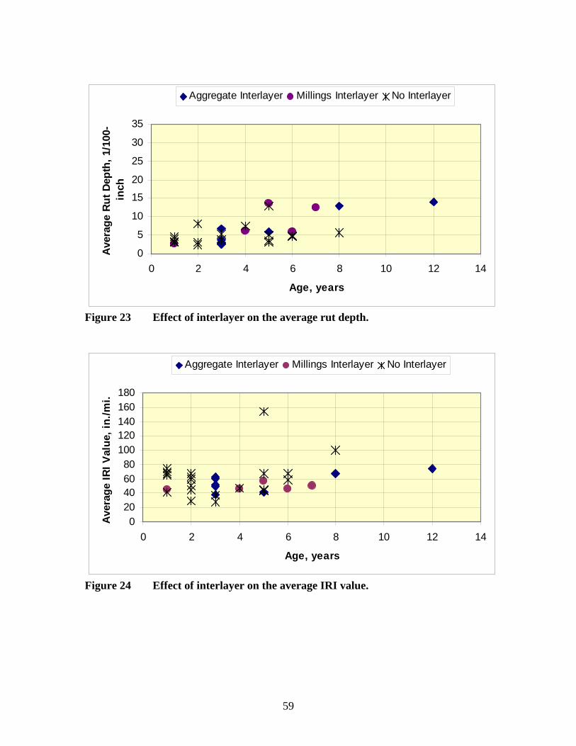
0
5
10
15
20
25
30
35
0 2 4 6 8 10 12 14
Age, years
Ave
rage
Rut
Dep
th, 1
/100
-in
ch
Aggregate Interlayer Millings Interlayer No Interlayer
Figure 23 Effect of interlayer on the average rut depth.
0 20 40 60 80
100 120 140 160 180
0 2 4 6 8 10 12 14
Age, years
Ave
rage
IRI V
alue
, in.
/mi.
Aggregate Interlayer Millings Interlayer No Interlayer
Figure 24 Effect of interlayer on the average IRI value.
59
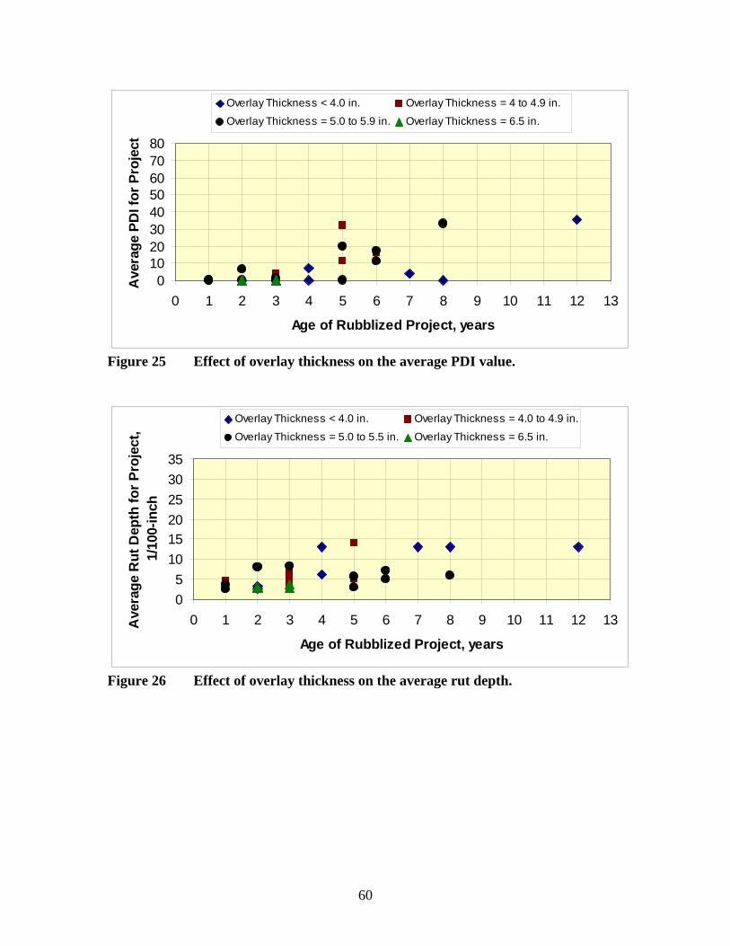
0 10 20 30 40 50 60 70 80
0 1 2 3 4 5 6 7 8 9 10 11 12 13
Age of Rubblized Project, years
Ave
rage
PD
I for
Pro
ject
Overlay Thickness < 4.0 in. Overlay Thickness = 4 to 4.9 in.
Overlay Thickness = 5.0 to 5.9 in. Overlay Thickness = 6.5 in.
Figure 25 Effect of overlay thickness on the average PDI value.
0 5
10 15 20 25 30 35
0 1 2 3 4 5 6 7 8 9 10 11 12 13
Age of Rubblized Project, years
Ave
rage
Rut
Dep
th fo
r Pro
ject
,1/
100-
inch
Overlay Thickness < 4.0 in. Overlay Thickness = 4.0 to 4.9 in.
Overlay Thickness = 5.0 to 5.5 in. Overlay Thickness = 6.5 in.
Figure 26 Effect of overlay thickness on the average rut depth.
60
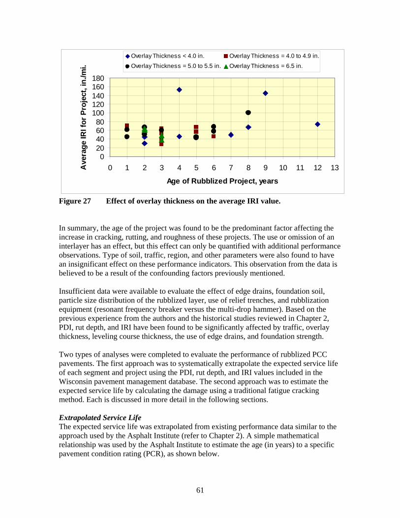
0 20 40 60 80
100 120 140 160 180
0 1 2 3 4 5 6 7 8 9 10 11 12 13
Age of Rubblized Project, years
Ave
rage
IRI f
or P
roje
ct, i
n./m
i.
Overlay Thickness < 4.0 in. Overlay Thickness = 4.0 to 4.9 in.
Overlay Thickness = 5.0 to 5.5 in. Overlay Thickness = 6.5 in.
Figure 27 Effect of overlay thickness on the average IRI value.
In summary, the age of the project was found to be the predominant factor affecting the increase in cracking, rutting, and roughness of these projects. The use or omission of an interlayer has an effect, but this effect can only be quantified with additional performance observations. Type of soil, traffic, region, and other parameters were also found to have an insignificant effect on these performance indicators. This observation from the data is believed to be a result of the confounding factors previously mentioned.
Insufficient data were available to evaluate the effect of edge drains, foundation soil, particle size distribution of the rubblized layer, use of relief trenches, and rubblization equipment (resonant frequency breaker versus the multi-drop hammer). Based on the previous experience from the authors and the historical studies reviewed in Chapter 2, PDI, rut depth, and IRI have been found to be significantly affected by traffic, overlay thickness, leveling course thickness, the use of edge drains, and foundation strength.
Two types of analyses were completed to evaluate the performance of rubblized PCC pavements. The first approach was to systematically extrapolate the expected service life of each segment and project using the PDI, rut depth, and IRI values included in the Wisconsin pavement management database. The second approach was to estimate the expected service life by calculating the damage using a traditional fatigue cracking method. Each is discussed in more detail in the following sections.
Extrapolated Service Life The expected service life was extrapolated from existing performance data similar to the approach used by the Asphalt Institute (refer to Chapter 2). A simple mathematical relationship was used by the Asphalt Institute to estimate the age (in years) to a specific pavement condition rating (PCR), as shown below.
61

PCR = −1.3149(Age) + 99.439 (1)
Similarly, the Ontario Ministry of Transportation developed the following mathematical relationship to estimate the pavement condition index for estimating the time to rehabilitation for various types of flexible pavements and HMA overlays.
205 − DMI C
Where: RCR = Ride comfort rating DMI = Distress Manisfestation Index C, S = Regression parameters (C=1.077 and S=0.00 for actual equipment
measured values; C=0.924 and S=8.856 for subjective values of RCR).
Von Quintus et al (2004) used a similar procedure to predict the distress index for flexible pavements and HMA overlays for use in life cycle cost analyses for the Ontario
⎞⎟⎠
Ministry of Transportation. That mathematical relationship used is given below.
⎛⎜⎝
PCI = 100(0.1[RCR])0.5 S (2) + 205
b ⎞⎟ ⎟ ⎟
100 1⎛⎜ ⎜ ⎜
⎛⎜⎜
⎞⎟⎟
t−a
tdesign⎝ ⎠PDI = − e (3)
⎠⎝Where:
t = Time in years. tdesign = Design life or period in years. a,b = Regression constants that are structure and mixture dependent (typically
for flexible pavements with strong base layers, a = 0.35 and b = .25; for the Wisconsin rubblized projects, a = 1.0 to 2.0 [average value of about 1.5] and b = 1.5).
The regression constants a and b were determined for the Wisconsin rubblized projects and found to be independent of overlay thickness, soil type, traffic and region, but dependent on the time before and after 1998. Figure 28 shows an example of the predicted versus measured PDI values for one rubblization project using equation 3. This extrapolation process and Figures 18 to 26 were used to estimate the age to a PDI value of 75, a rut depth of 0.35 inches, and an IRI value of 140 in./mi. These trigger or threshold values were selected simply for comparison purposes, and require significant extrapolation in the data (refer to Figures 18 to 20 and 28). This type of data analysis has one underlying major assumption: it is assumed that all rubblization projects were designed using the same procedure and design life.
Table 6 summarizes the service life extrapolated using PDI, rut depth, and IRI. Wisconsin’s Facility Development Manual recommends that an expected service life of 22 years be used for HMA placed over rubblized PCC pavements for estimating life cycle costs (Chapter 14 – Pavements, Sections 15 – Pavement Type Selection, Subject 10 – LCCA Computation Parameters). Considering the extrapolation process, the 22 year
62
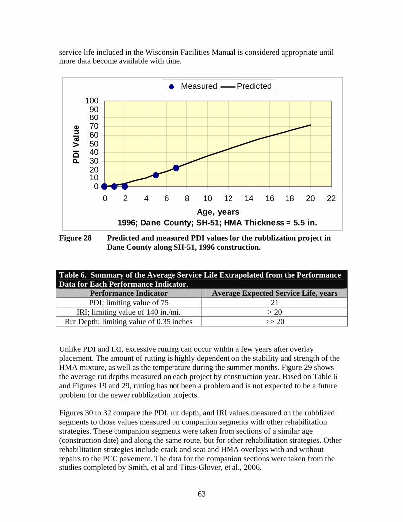
service life included in the Wisconsin Facilities Manual is considered appropriate until more data become available with time.
0 10 20 30 40 50 60 70 80 90
100
0 2 4 6 8 10 12 14 16 18 20 22 Age, years
1996; Dane County; SH-51; HMA Thickness = 5.5 in.
PD
I Val
ue
Measured Predicted
Figure 28 Predicted and measured PDI values for the rubblization project in Dane County along SH-51, 1996 construction.
Table 6. Summary of the Average Service Life Extrapolated from the Performance Data for Each Performance Indicator.
Performance Indicator Average Expected Service Life, years PDI; limiting value of 75 21
IRI; limiting value of 140 in./mi. > 20 Rut Depth; limiting value of 0.35 inches >> 20
Unlike PDI and IRI, excessive rutting can occur within a few years after overlay placement. The amount of rutting is highly dependent on the stability and strength of the HMA mixture, as well as the temperature during the summer months. Figure 29 shows the average rut depths measured on each project by construction year. Based on Table 6 and Figures 19 and 29, rutting has not been a problem and is not expected to be a future problem for the newer rubblization projects.
Figures 30 to 32 compare the PDI, rut depth, and IRI values measured on the rubblized segments to those values measured on companion segments with other rehabilitation strategies. These companion segments were taken from sections of a similar age (construction date) and along the same route, but for other rehabilitation strategies. Other rehabilitation strategies include crack and seat and HMA overlays with and without repairs to the PCC pavement. The data for the companion sections were taken from the studies completed by Smith, et al and Titus-Glover, et al., 2006.
63
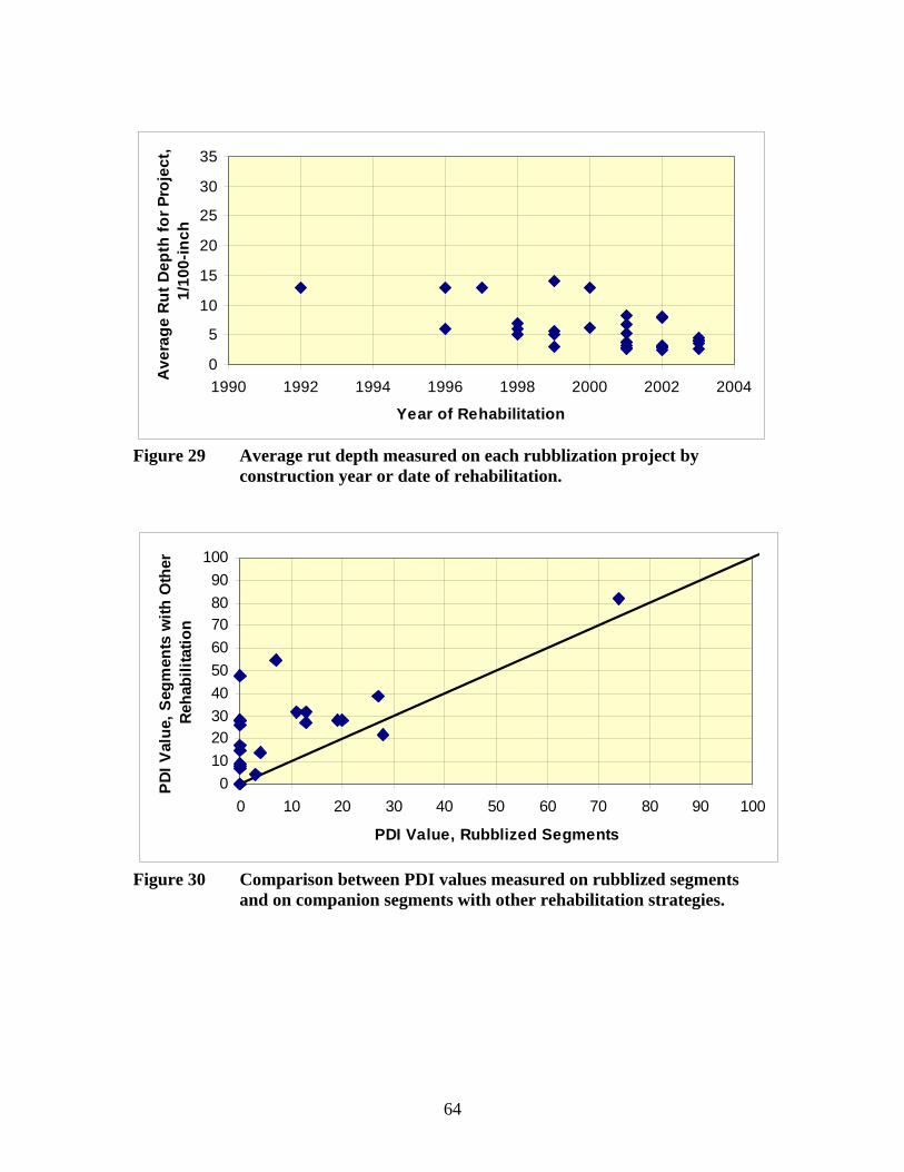
0
5
10
15
20
25
30
35
1990 1992 1994 1996 1998 2000 2002 2004
Year of Rehabilitation
Ave
rage
Rut
Dep
th fo
r Pro
ject
, 1/
100-
inch
Figure 29 Average rut depth measured on each rubblization project by construction year or date of rehabilitation.
0 10 20 30 40 50 60 70 80 90
100
0 10 20 30 40 50 60 70 80 90 100
PDI Value, Rubblized Segments
PDI
Val
ue, S
egm
ents
with
Oth
erR
ehab
ilita
tion
Figure 30 Comparison between PDI values measured on rubblized segments and on companion segments with other rehabilitation strategies.
64
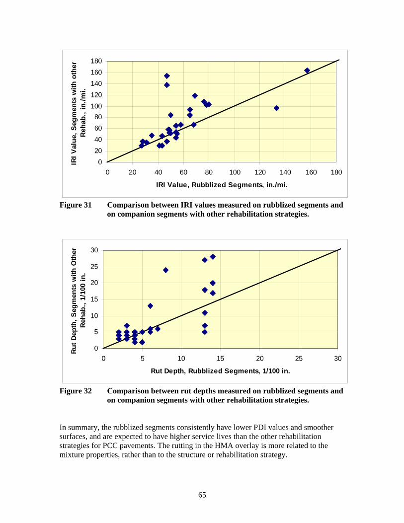
0 20 40 60 80
100 120 140 160 180
0 20 40 60 80 100 120 140 160 180
IRI Value, Rubblized Segments, in./mi.
IRI V
alue
, Seg
men
ts w
ith o
ther
Reh
ab.,
in./m
i.
Figure 31 Comparison between IRI values measured on rubblized segments and on companion segments with other rehabilitation strategies.
Rut
Dep
th, S
egm
ents
with
Oth
erR
ehab
., 1/
100
in.
30
25
20
15
10
5
0 0 5 10 15 20 25
Rut Depth, Rubblized Segments, 1/100 in.
Figure 32 Comparison between rut depths measured on rubblized segments and on companion segments with other rehabilitation strategies.
In summary, the rubblized segments consistently have lower PDI values and smoother surfaces, and are expected to have higher service lives than the other rehabilitation strategies for PCC pavements. The rutting in the HMA overlay is more related to the mixture properties, rather than to the structure or rehabilitation strategy.
65
30
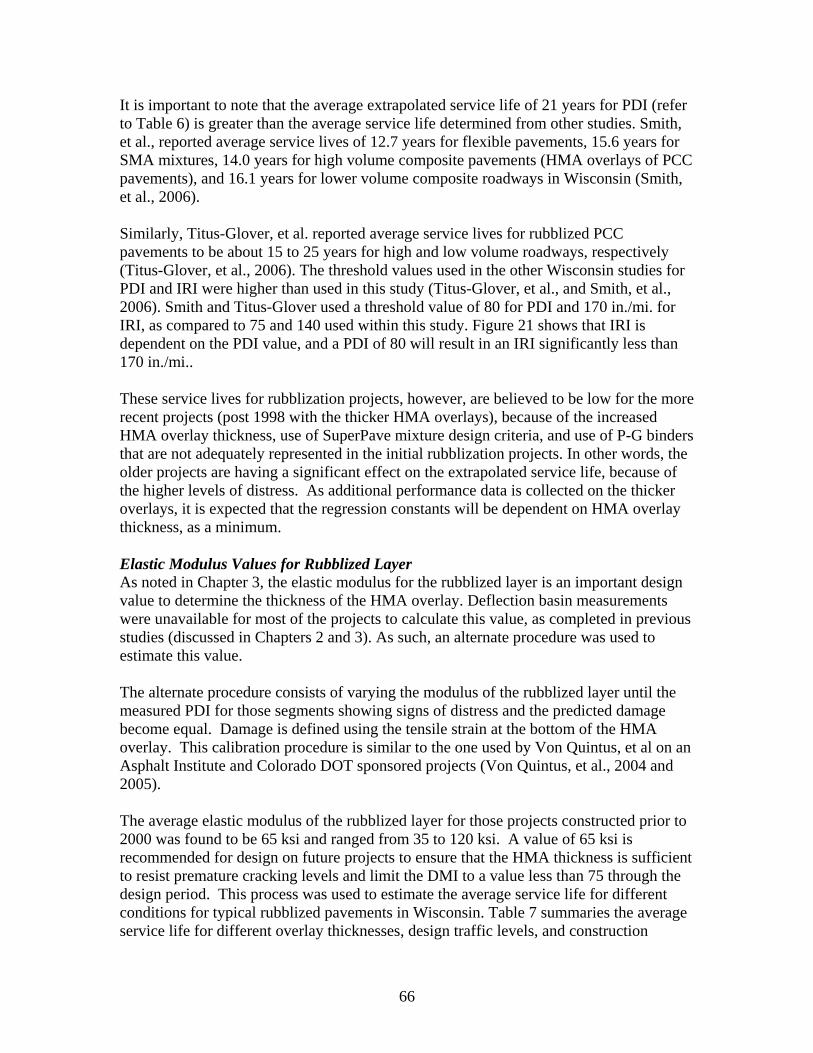
It is important to note that the average extrapolated service life of 21 years for PDI (refer to Table 6) is greater than the average service life determined from other studies. Smith, et al., reported average service lives of 12.7 years for flexible pavements, 15.6 years for SMA mixtures, 14.0 years for high volume composite pavements (HMA overlays of PCC pavements), and 16.1 years for lower volume composite roadways in Wisconsin (Smith, et al., 2006).
Similarly, Titus-Glover, et al. reported average service lives for rubblized PCC pavements to be about 15 to 25 years for high and low volume roadways, respectively (Titus-Glover, et al., 2006). The threshold values used in the other Wisconsin studies for PDI and IRI were higher than used in this study (Titus-Glover, et al., and Smith, et al., 2006). Smith and Titus-Glover used a threshold value of 80 for PDI and 170 in./mi. for IRI, as compared to 75 and 140 used within this study. Figure 21 shows that IRI is dependent on the PDI value, and a PDI of 80 will result in an IRI significantly less than 170 in./mi..
These service lives for rubblization projects, however, are believed to be low for the more recent projects (post 1998 with the thicker HMA overlays), because of the increased HMA overlay thickness, use of SuperPave mixture design criteria, and use of P-G binders that are not adequately represented in the initial rubblization projects. In other words, the older projects are having a significant effect on the extrapolated service life, because of the higher levels of distress. As additional performance data is collected on the thicker overlays, it is expected that the regression constants will be dependent on HMA overlay thickness, as a minimum.
Elastic Modulus Values for Rubblized Layer As noted in Chapter 3, the elastic modulus for the rubblized layer is an important design value to determine the thickness of the HMA overlay. Deflection basin measurements were unavailable for most of the projects to calculate this value, as completed in previous studies (discussed in Chapters 2 and 3). As such, an alternate procedure was used to estimate this value.
The alternate procedure consists of varying the modulus of the rubblized layer until the measured PDI for those segments showing signs of distress and the predicted damage become equal. Damage is defined using the tensile strain at the bottom of the HMA overlay. This calibration procedure is similar to the one used by Von Quintus, et al on an Asphalt Institute and Colorado DOT sponsored projects (Von Quintus, et al., 2004 and 2005).
The average elastic modulus of the rubblized layer for those projects constructed prior to 2000 was found to be 65 ksi and ranged from 35 to 120 ksi. A value of 65 ksi is recommended for design on future projects to ensure that the HMA thickness is sufficient to resist premature cracking levels and limit the DMI to a value less than 75 through the design period. This process was used to estimate the average service life for different conditions for typical rubblized pavements in Wisconsin. Table 7 summaries the average service life for different overlay thicknesses, design traffic levels, and construction
66
periods. These expected service lives are similar to those reported by other agencies under Chapter 2.
Table 7. Average Service Life for Different Conditions for Rubblized Pavements in Wisconsin. HMA Mixtures (refer to
Figure 13) HMA Overlay Thickness, in.
20-Year Design Traffic Levels, millions 3 10 30
1990 to 1997 Construction Period
3 20 8 3 5 >30 17 8
6.5 >30 >30 14
1998 to 2003 Construction Period
3 23 9 3 5 >30 25 12
6.5 >30 >30 21
5.4 Summary of Findings from the Performance Analysis
The recommended guidelines for designing and constructing rubblized pavements are included in Appendix A, and represent the findings referred to in Chapters 2 through 5. The following summarizes some of the more important findings from the limited performance analyses completed on the Wisconsin rubblization projects.
• There is a difference in the performance characteristics between those rubblization projects built prior to 1998 and those built after 1998. The average service life expected or extrapolated for those pavement built between 1990 and 1997 is around 17 years, while the service life is expected to equal or exceed the design life for those projects completed after 1997 (refer to Table 7). The extrapolated service life for the newer projects needs to be confirmed with more performance data, as the segments become older. The service life included in Wisconsin’s Facilities Manual for rubblized PCC pavements with HMA surfaces of 22 years is considered appropriate.
• Age was found to be the predominant factor in determining the performance trends and characteristics of rubblized PCC pavements in Wisconsin. Age was also found to be the predominant factor from the Asphalt Institute study (refer to equation 1).
• The use of an interlayer placed above the rubblized PCC layer prior to overlay is believed to be important and have an effect of the performance on the HMA overlay. However, there was insufficient data to define its effect on performance.
• There are an insufficient number of rubblization projects and insufficient performance data to determine the effect of overlay thickness, soil type, region, traffic, PCC breakage and particle distribution, and drainage on the performance characteristics of rubblized pavements. HMA overlay thickness is believed to be
67
important, but is difficult to quantify because of the confounding factors that changed over time on the Wisconsin rubblization projects. As such, it was judged inappropriate to have all projections of service life based on the old rehabilitation projects (constructed prior to 1998) that exhibit higher levels of distress and roughness.
• The predominant distress types exhibited on some of the older rubblization projects in Wisconsin and in other agencies are longitudinal cracking outside the wheel path and transverse cracking. However, many of the projects reviewed and evaluated have exhibited none to minor levels of distress and are projected to meet their design requirements.
• Rutting was not and should not be a controlling factor for the newer rubblization projects being overlaid with HMA mixtures being designed using the performance graded binder specification and SuperPave mixture design criteria or designed with Wisconsin’s previous mixture design procedure.
• The average elastic modulus determined for the rubblized PCC layer on the Wisconsin projects is 65 ksi, and is similar to those values used in developing the rubblization catalog for MAPA (Von Quintus and Tam, 2000 and 2001). It is recommended that this value be used in rehabilitation design to determine the HMA overlay thickness above the rubblized layer. It is also recommended that FWD deflection basins measurements be made on some selected projects during the 2007 and other construction seasons after the first lift of HMA is placed on the rubblized PCC layer and after construction has been completed to confirm the use of this value in design. The elastic layer of the rubblized and other layers can be back-calculated in accordance with the procedure used to populate the LTPP database (Von Quintus and Simpson, 1999; and Von Quintus and Killingsworth, 1997 and 1998).
• The minimum in place modulus for the foundation layers supporting the PCC slabs is 10,000 psi to ensure adequate fracturing of the PCC slabs. This value can be determined using FWD deflection basin test results. Resilient modulus values measured in the laboratory in accordance with AASHTO T307 at an equivalent stress state would be about 5,000 psi using the C-factors or ratios between the laboratory-measured resilient modulus and backcalculated elastic modulus values (Von Quintus and Killingsworth; 1997 and 1998).
• The minimum overlay thickness recommended for rubblized PCC slabs is 4 inches from a constructability standpoint, even though some of the 3-inch overlays are providing good performance in Wisconsin. This value will need to be confirmed with additional performance data over time.
68
CHAPTER 6 SUMMARY OF FINDINGS AND CONCLUSIONS
Chapter 6 provides a summary of the findings and conclusions from this study, as well as, recommendations regarding the future use of rubblization of PCC pavements in Wisconsin. The findings and conclusions are presented in terms of answering the questions that were listed in Chapter 1. Appendix A provides suggested guidelines for designing and constructing rubblized PCC pavements to supplement existing standards and specifications already in existence in Wisconsin. Appendix A was prepared and written as a standalone document to be consistent with Wisconsin’s Facilities Development Manual.
The findings and conclusions from this study were based pavement performance histories and construction information from the Department’s databases and records. Sufficient data, however, were unavailable to determine the effect of various site conditions/features on rubblizing PCC slabs, as well as on pavement performance in Wisconsin. Thus, many of the findings and conclusions were based on information and data available from Wisconsin’s rubblization projects and other agency studies documented in the literature. The recommendations section of this chapter provides activities that the Department should consider to confirm the design criteria and decision factors suggested for use in Wisconsin.
6.1 Findings and Conclusions
1. Is the rubblization of PCC pavements a cost-effective rehabilitation strategy, as compared to other repair techniques?
The answer to this question is yes, but under the right conditions or conditions conducive to rubblizing PCC pavements. Those conditions are addressed in answering some of the following questions and are identified included in flow chart form in Appendix A.
One of the most important conditions is the support or strength of the foundation. It has been found from numerous studies that the foundation should have an equivalent elastic modulus of 10,000 psi for the rubblization process to be effective and is based on back-calculating layer elastic modulus values from deflection basins. As noted in Chapter 5, this backcalculated elastic modulus value is consistent with a laboratory measured resilient modulus value of 5,000 psi.
Chapter 5 summarized the performance analyses of the rubblized projects that have been built in Wisconsin. One of the significant findings was the difference in performance characteristics between those projects built before and after 1998. This time is when various changes were being made to the DOT’s specifications and construction practices. Those rubblized projects built after 1998 are expected to equal or exceed their design lives based on an extrapolation of predicted pavement performance. None of these newer rubblized projects have exceeded the failure criteria used in this study, so the expected service life presented within this study is based on extrapolations from existing surface
69
conditions of these projects. Most life cycle cost analyses that have been performed show a 25 to 50 percent reduction in construction costs, as compared to other rehabilitation strategies.
2. What parameters need to be considered in determining if rubblization is a feasible strategy for a specific project?
A detailed site investigation should be performed on any rehabilitation project. This site investigation should include strength testing of the foundation materials, the presence of water, and condition of the existing PCC pavement. As noted above, one of the most important parameters is the strength of the foundation layers. A minimum back-calculated elastic modulus value of 10,000 psi has been defined for the foundation layers. Appendix A provides a detailed flow chart for identifying when the rubblization process is feasible.
3. What are the recommended values for the design inputs for rubblized PCC layers?
Age and HMA overlay thickness were found to be the predominant factors relative to the performance of rubblized PCC pavements. Other design features were considered and included in the evaluation, but were found to have an insignificant effect on performance. There were simply too many confounding factors between the existing rubblization projects to detect differences in pavement performance caused by other site factors and features. Additional time and performance observations will be needed to determine the significance of other design features. A discussion on future performance analyses is included in answering question 6.
The WisPAVE program is used to design flexible pavements by the Wisconsin DOT. This program uses the design equation included in the 1972 AASHTO Interim Design Guide. The specific design input is the structural layer coefficient for each structural layer within the flexible pavement. Many agencies, including Wisconsin, are considering use of the M-E Pavement Design Guide developed under NCHRP project 1-37A. Thus, the following lists the design values recommended for the rubblized PCC layer for both design procedures, which were based on the performance analyses and data presented in Chapter 5.
� AASHTO Structural Design Guide – A structural layer coefficient of 0.22 is recommended for use in design. This value could be increased as additional performance data become available. One reason for this lower value is to ensure that there is a sufficient thickness of HMA above the rubblized PCC layer.
� M-E Pavement Design Guide – An elastic layer modulus value of 65,000 psi is recommended for use in design. This value is less than the value recommended in the NAPA Information Series 117 and in the NCHRP 1-37A final report. The lower modulus value is based on performance analyses of rubblized pavements built in Wisconsin. In other words, the average elastic modulus value of 65,000 psi was determined by matching the predicted to observed pavement performance.
70

This mathematically derived value should be confirmed over time by monitoring existing and future rubblization projects.
4. What are some of the problems that have been encountered when using the rubblization strategy?
The following lists some of the construction and performance problems that have been encountered relative to rubblization of PCC pavements.
� HMA layer thickness that is too thin. The structural layer coefficient or elastic modulus for the rubblized layer is believed to be too high, resulting in HMA overlays that are too thin for the existing traffic and constructability issues. A higher minimum HMA layer thickness is recommended for use in Wisconsin – 4 inches. Wisconsin recognized this deficiency from previous studies and the earlier projects and increased the minimum HMA layer thickness around 1998. The structural layer coefficient and elastic layer modulus values recommended for use in design were provided above in answer to question 3. The AASHTO structural layer coefficient recommended from this study (0.22) is within the range recommended in Wisconsin’s Facility Development Manual (0.20 to 0.24).
� The most common type of distress exhibited along a rubblized PCC pavement includes transverse and longitudinal cracking. The transverse and longitudinal cracking have been found to be the result of not breaking the PCC slabs sufficiently to eliminate the reflection cracks above the joints and cracks. Test pits should be used to confirm that the rubblization process is breaking the PCC into small enough pieces that reflection cracking will not be a problem.
� Omission of drainage layers within the rehabilitation project, or allowing saturated subsurface layers to properly drain, eliminating the free water effect. Drainage layers should be considered for use in all rehabilitation designs for rubblized PCC pavements. The drainage system should be placed prior to the rubblization process to allow any saturated materials to drain and their strength to increase.
� Not identifying soft spots along the project that result in the PCC particles being depressed into the foundation materials. A detailed site investigation should be completed to reduce the probability of missing any soft spots along the project. This detailed investigation should include nondestructive FWD deflection basin testing, as well as destructive testing.
For example, deflection basins should be measured along a proposed rehabilitation project to estimate the in place response characteristics of the PCC pavement and foundation soil. The frequency of the deflection basin tests should be sufficient to determine the variability of the foundation and locate any soft areas. Equivalent elastic modulus values of the foundation soils and other pavement layers should be backcalculated from the deflection basin data.
71
Destruction tests should be performed and samples of the supporting soils recovered to confirm weak and strong areas of the project, as defined from the deflection basin tests. The dynamic cone penetrometer (DCP) is a device that can be used to estimate the in place strength of the supporting unbound pavement layers and foundation, but requires coring the PCC. This pavement investigation and evaluation process for rehabilitation design is consistent with the M-E PDG developed under NCHRP Project 1-37A.
5. What type of test and the frequency of tests are recommended for the rubblization process?
There are two types of tests that are recommended for controlling and confirming the design parameters for rubblized PCC layers. First, test strips should be used to confirm or accept the rubblization process – breaking the PCC slab into discrete particles. The frequency of the test strips should be up to the project engineer. It is recommended that one test strip be used for each different subsurface condition found during the detailed investigation.
Second, deflection basin tests should be performed after the first lift of HMA has been placed and at project completion. These deflection basins tests are discussed within the next question, and are used to confirm the design parameters. The deflection basin tests should be performed on a 100 to 200 foot interval, at least at the beginning, but depends on the longitudinal variability of the PCC slabs and subsurface conditions. The less variable conditions, the longer the testing interval. For uniform support conditions, the deflection basin test interval could be increased up to 1,000 feet. This interval should be determined by the project engineer.
6. What data are needed to monitor and confirm the performance of this rehabilitation strategy?
As noted in Chapter 5, age and overlay thickness has a significant effect on the performance of rubblized PCC pavements. More importantly, there is a substantial difference in the performance between the rubblization projects built before and after 1998. The service life for those projects built after 1998 is expected to exceed the design life based on early performance observations. Additional performance data are needed to confirm this finding that was based on just four to six years of performance data.
The data needed to confirm the performance predictions or expectations include distress measurements, as a minimum. Appendix B provides a summary of the performance history of the rubblized PCC projects included in this study. Performance data collected in future years should be added to this appendix to ensure that the projects meet there design expectations.
As noted in Chapter 5, there are insufficient data to determine the significance of other design and site features – drainage layers, high water tables, leveling course, etc. The sections included in Appendix B should continue to be monitored for collecting
72
additional data and additional rubblized projects added to this list as they are built. Statistical analyses of the performance data can then be used to determine the effect of the other design and site features.
It is also recommended that FWD deflection basin data be measured on some future rubblized projects, after the first lift of HMA has been placed and at project completion. The following lists and summarizes the types of data and testing needed on future projects for confirming the design parameters and analyses.
� Deflection basin data should be measured on proposed rubblization projects with different conditions (depth to a rigid layer, depth to a water table, soil type, resilient modulus of the foundation, etc.). The pavement and foundation modulus should be backcalculated from these deflection basin data. In addition, destructive testing should be conducted in each area with significantly different response characteristics – high and low elastic modulus values. The destructive testing and sampling needs to be completed prior to the rubblization process to confirm the critical backcalculated modulus values of the foundation.
� Deflection basin data should also be measured after the first lift of HMA has been placed on the rubblized PCC layer to identify areas with different response characteristics of the rubblized layer. The elastic modulus of the rubblized PCC layer should also be calculated to determine the average and standard deviation of the backcalculated modulus values of the rubblized layer, and to identify areas with significantly different elastic modulus values (e.g.; areas with backcalculated modulus values of the rubblized layer greater than 150,000 psi and less than 50,000 psi). For the backcalculation process, the rubblized PCC layer may need to be divided into layers for thicker PCC slabs (9 inches and above) and those with reinforcing steel or welded wire fabric to reduce the error between the calculated and measured deflection basins.
� Gradation testing and/or visual observations of the rubblized material should be completed to determine whether the elastic modulus calculated from the deflection basins is related to the size of the particles in the rubblized layer.
6.2 Recommendations
In summary, it is recommended that the Wisconsin DOT continue to use PCC rubblization as a valid pavement rehabilitation strategy. Many other studies have concluded with this same recommendation. Appendix A provides the design manual and guidelines that the Wisconsin DOT should consider for rehabilitation design and rubblizing PCC pavements. Appendix A was prepared and written as a standalone document to be consistent with Wisconsin’s Facilities Development Manual.
The guidelines included in Appendix A were developed from an analysis of the performance data on rubblized PCC projects in Wisconsin. The Wisconsin data was
73
supplemented from other studies with similar site conditions and features, when sufficient information was unavailable on the Wisconsin rubblization projects.
As noted in the above section, some of the findings were based on a mathematical analysis and extrapolation of pavement performance observations of rubblized pavements built in Wisconsin. For example, the average elastic modulus value of 65,000 psi for the rubblized layer was determined by matching the predicted to observed pavement performance. This mathematically derived value and other extrapolations should be confirmed over time by monitoring existing and future rubblization projects. The following provides specific recommendations for future analyses.
1. It is recommended that at least some of the projects included in Appendix B be monitored periodically and analyzed in the future. This monitoring should include distress observations and deflection basin testing at reasonably close intervals to determine the load-response characteristics of the rubblized pavement and HMA overlay. The average elastic modulus values for each layer and the foundation should be backcalculated from the deflection basin data. Statistical analyses of the performance data can then be used to determine the effect of other design and site features, as well as confirm the performance predictions included in this study.
2. The final recommendation is to measure deflection basins with the FWD on future rubblized projects after the first lift of HMA has been placed and at project completion. Destructive sampling and testing should also be completed after the rubblization process to measure the gradation of the rubblized PCC layer and include that data in Wisconsin’s rubblization database. These data can be used to confirm the design parameters and performance characteristics included and referred to in Chapter 5 and Appendix A. The following values should be confirmed with future analyses, as a minimum.
a. Confirm the extrapolated service lives of the rubblized pavement structure and minimum HMA thickness (excluding any leveling course used in the rehabilitation project) provided in Chapter 5.
b. Confirm the minimum foundation support condition or elastic modulus of the foundation – a backcalculated modulus value of 10,000 psi; prior to the rubblization process.
c. Determine the minimum and maximum average elastic modulus values for the rubblized PCC layer that will optimize pavement performance or minimize pavement distress – a range of 50,000 to 150,000 psi.
d. Determine the impact of the foundation on the particle size distribution and backcalculated modulus of the rubblized PCC layer. If a relationship is found and confirmed, use of this relationship could reduce or eliminate the need for the use of continued test strips throughout a rubblization project.
74
REFERENCES
Reports and Research Documents
Ambroz, Joanna K. and Michael I. Darter, Initial Evaluation of the SPS-6 Experiment, Draft Final Report, Contract No. DTFH61-96-C-00003, Federal Highway Administration, Washington, DC, April 2000.
Applied Research Associates, Inc., Guide for Mechanistic-Empirical Design of New and Rehabilitated Pavement Structures, Draft Final Report, NCHRP Project 1-37A, National Cooperative Highway Research Program, Transportation Research Board, National Research Council, Washington, DC, March 2004.
Asphalt Institute, Asphalt Overlays for Highway and Street Rehabilitation, Manual Series 17 (MS-17), Asphalt Institute, January 2000.
AASHTO, AASHTO Guide for Design of Pavement Structures, American Association of State Highway and Transportation Officials, Washington, DC, 1993.
Boyer, R. and W. Jones, State-of-the practice Rubblization of Heavy Load Concrete Airfield Pavements, Challenges and New Technologies, Proceeding of the ASCE Conference, Airfield Pavements, Challenges and New Technologies, American Society of Civil Engineers, September 2003.
Decker, Dale S., and Kent R. Hansen, Design and Construction of HMA Overlays on Rubblized PCC Pavements, State of the Practice, Transportation Research Circular No. E-C087, Rubblization of Portland Cement Concrete Pavements, Transportation Research Board, National Academies, National Research Council, Washington, DC, January 2006.
Fitts, GL, Performance Observations of Rubblized PCC Pavements, Second International Symposium on Maintenance and Rehabilitation of Pavements and Technological Control, National Center for Asphalt Technology, Auburn, Alabama, 2001.
Gulen,S. Noureldin, A.S., and Weaver, J. Life and Cost Comparison of Three Rehabilitation Techniques on I-65 Between SR-2 And SR-114, Report No. FHWA/IN/JTRP – 2004/8, Prepared for the Indiana Department of Transportation, Federal Highway Administration, Washington, DC, June 2004.
Gulen,S. Noureldin, A.S., Evaluation of Concrete Pavement Rehabilitation Techniques on I-65 in Indiana, Transportation Research Record 1730, Transportation Research Board, Washington, DC, 2000.
Heckel, LB, Rubblizing with Bituminous Concrete Overlays - 10 years Experience in Illinois, Final Report IL-PRR-137, Illinois Department of Transportation, April 2002.
75

Kim, YR and S. Mun, Determination of Subgrade Strength Under Intact Cement Concrete Slabs for Rubblization Projects, Final Report FHWA/NC/2002-010, Federal Highway Administration, Washington, DC, May 2002.
Morian, DA, L. Coleman, DJ Frith, SM Stoffels, and D. Dawood, Pennsylvania SPS-6 Performance at 10 years: Evaluation of Concrete Pavement Rehabilitation Strategies, Transportation Research Record 1823, Transportation Research Board, Washington, DC, 2003.
NAPA, Guidelines for the Use of HMA Overlays to Rehabilitate PCC Pavements, National Asphalt Pavement Association, Information Series 117, 1994.
Niederquell, MG, GY Baladi, and K. Chatti, Rubblization of Concrete Pavements: Field Investigation, Transportation Research Record 1730, Transportation Research Board, Washington, DC, 2000.
Sebaaly, PE; GM Bazi, and Y. Vivekanathan, Evaluation of New Pavement Technologies in Nevada, Report No: RDT-03-034, Interim Report, Report No. 13AX-1, Nevada Department of Transportation, March 2003.
Shinners, Matt, Rubblization Project Listing provided by Matt Shinners with Antigo, Inc., 2005.
Smith, K.L., Leslie Titus-Glover, S. Rao, H.L. Von Quintus, and M. Stanley, Life Cycle Cost Analysis of SMA Pavements and SMA Application Guidelines, Final Report Project No. WHRP 0092-04-06, Wisconsin Highway Research Program, Wisconsin Department of Transportation, Madison, Wisconsin, 2006.
Thompson, Marshall R., Breaking/Cracking and Seating Concrete Pavements, NCHRP Synthesis of Highway Practice 144, National Cooperative Highway Research Program, Transportation Research Board, National Research Council, Washington, DC, 1989.
Titus-Glover, L., K.L. Smith, J. Mallela, and M. Stanley, Validation of Wisconsin Pavement Service Lives, Final Report, Applied Research Associates, Inc., prepared for Wisconsin Department of Transportation, Madison, Wisconsin, March 2006.
Velez-Vega, E., Procedures for the Design of Asphalt Overlays Over Airfield Rubblized or Crack and Seat PCC Pavements, Draft Preliminary Report, Engineering Research and Development Center, U.S. Army Corp of Engineers, 2005.
Von Quintus, Harold and Brian Killingsworth, Design Pamphlet for the Determination of Layered Elastic Moduli for Flexible Pavement Design, Publication No. FHWA-RD-97077, Federal Highway Administration, Washington, DC, June 1997.
76
Von Quintus, H. L. and Brian Killingsworth, Analyses Relating to Pavement Material Characterizations and Their Effects on Pavement Performance, Publication No. FHWARD-97-085, Federal Highway Administration, Washington, DC, January 1998.
Von Quintus, H.L. and A.L. Simpson, Documentation of the Back-Calculation of Layer Parameters for LTPP Test Sections, Volume II: Layered Elastic analysis for Flexible and rigid Pavements, Draft Final Report under Contract DTFH61-96-C-00003, Federal Highway Administration, Washington, DC, January 1999.
Von Quintus, Harold L. and Weng-On Tam, HMA Overlay Design for Rubblization of PCC Slabs, Report No. 3066, Brent Rauhut Engineering, Inc., Final Report prepared for Michigan Asphalt Pavement Association, Lansing, Michigan, November 2000.
Von Quintus, H.L., Unpublished deflection data collected along US Highway 23 – both before and after rubblization in different areas of the project, deflection data collected by the Michigan DOT, 2001.
Specifications for Rubblized PCC Layers
Federal Aviation Administration (FAA), Engineering Brief No. 66, Rubblized Portland Cement Concrete Base Course, February 2004.
Arkansas DOT, “2003 Standard Specifications for Highway Construction,” 2003. (http://www.ahtd.state.ar.us/Contract/progcon/general/STDSPECS_2003.HTM)
Michigan DOT, “2003 Standard Specifications for Construction,” 2003 (http://mdotwas1.mdot.state.mi.us/public/specbook/)
Ohio DOT, “2005 Construction and Material Specifications,” 2005 (http://www.dot.state.oh.us/construction/OCA/Specs/2005CMS/2005_ODOT_C&MS.htm)
Ohio DOT, “Geotechnical Bulletin GB1 on Plan Subgrades,” 2003 (http://www.dot.state.oh.us/Construction/OCA/Soil_Pipe/GB1%20Plan%20Subgrades.pdf)
Indiana Dot, “2006 Standard Specifications,” 2005 (accessed at http://www.in.gov/dot/div/contracts/standards/book/sep06/sep.htm)
Heckel, LB, “Rubblizing with Bituminous Concrete Overlays - 10 years Experience in Illinois,” Final Report IL-PRR-137, April 2002. (http://www.dot.state.il.us/materials/research/pdf/137.pdf)
Aphalt Institute, “Grade Control Guidelines for Smooth Hot Mix Asphalt (HMA) Pavements with Emphasis on Overlays over Rubblized Portland Cement Concrete (PCC) Pavement,” IS-201, 2001
77

Wisconsin Highway Research Program University of Wisconsin-Madison
1415 Engineering Drive Madison, WI 53706
608/262-2013 www.whrp.org