Embed Size (px)
Citation preview
— Traditional layout wiring —
WIRINGHandbook for Toy Trains
Ray L. Plummer9 7 8 0 8 9 7 7 8 5 3 3 4
ISBN 978-0-89778-533-4
5 1 7 9 5
$17.95 U.S. 108375
Wire your layout the traditional wayThis handbook is the one guide to have handy when wiring a toy train layout. Classic Toy Trains columnist Ray L. Plummer provides easy-to-follow explana-tions, which are accompanied by numerous illustrations, photos, and sample wiring layouts.
The handbook describes how to
• Master the basics of electricity and wiring
• Hook up transformers, switches, and other components
• Select, connect, and solder wire
• Operate two trains using block or cab control
• Wire accessories and replace controllers
• Maintain and troubleshoot a layout
0 6 4 4 6 5 1 8 3 7 5 3
Wiring H
andbook for Toy TrainsPlum
mer
Hobby
www.KalmbachBooks.com
BKS-108375-CV.indd 1 7/28/08 1:25:03 PM

— Traditional layout wiring —
WIRINGHandbook for Toy Trains
Ray L. Plummer
BKS-108375-FM.indd 1 7/15/08 1:19:14 PM

Kalmbach Books 21027 Crossroads CircleWaukesha, Wisconsin 53186www.kalmbach.com/books
© 2008 by Kalmbach BooksAll rights reserved. This book may not be reproduced in part or in whole without written permission of the publisher except for brief excerpts for review.
Published in 200812 11 10 09 08 1 2 3 4 5
Manufactured in Canada
Cover photo: Engine, courtesy of Jack Sommerfeld. This Lionel no. 746 4-8-4 Norfolk & Western Railway class J Northern locomotive was catalogued in 1957-1960.
Publisher’s Cataloging-In-Publication Data
Plummer, Ray L. Wiring handbook for toy trains : traditional layout wiring / Ray L. Plummer.
p. : ill. ; cm.
Includes index. ISBN: 978-0-89778-533-4
1. Railroads--Models--Electric equipment. 2. Railroads--Models--Design and construction--Handbooks, manuals, etc. 3. Railroads--Models--Maintenance and repair--Handbooks, manuals, etc. 4. Digital control systems. I. Title.
TF197 .P58 2008625.1/9
Ray L. Plummer is a longtime contributor and columnist for Classic Toy Trains magazine. He has authored four books on toy trains including two on toy train repair.
BKS-108375-FM.indd 2 7/30/08 1:01:43 PM

Introduction . . . . . . . . . . . . . . . . . . . . . . . . . . . . . . . . . . . . . 4
GettingStarted 1 Basicelectricity . . . . . . . . . . . . . . . . . . . . . . . . . . . . . . . . . . 6 2 Rulenumberone . . . . . . . . . . . . . . . . . . . . . . . . . . . . . . . . 9
ExaminingElectricalComponents 3 Transformers . . . . . . . . . . . . . . . . . . . . . . . . . . . . . . . . . . .12 4 Electro-mechanicaldevices . . . . . . . . . . . . . . . . . . . . . .21 5 Switches . . . . . . . . . . . . . . . . . . . . . . . . . . . . . . . . . . . . . . .23
WiringaLayout 6 Wirebasics . . . . . . . . . . . . . . . . . . . . . . . . . . . . . . . . . . . . .29 7 Commongrounds . . . . . . . . . . . . . . . . . . . . . . . . . . . . . . .31 8 Buswires . . . . . . . . . . . . . . . . . . . . . . . . . . . . . . . . . . . . . . .34 9 Connections . . . . . . . . . . . . . . . . . . . . . . . . . . . . . . . . . . . .3610 Successfulsoldering . . . . . . . . . . . . . . . . . . . . . . . . . . . .38
OperatingTwoTrains11 Zonesofcontrol . . . . . . . . . . . . . . . . . . . . . . . . . . . . . . . .4112 Collisionprevention . . . . . . . . . . . . . . . . . . . . . . . . . . . . .4813 Automaticrouteselection . . . . . . . . . . . . . . . . . . . . . . .52
UsingAccessoriesandControllers14 Train-activatedaccessories . . . . . . . . . . . . . . . . . . . . . .5515 Gangedcontrollers . . . . . . . . . . . . . . . . . . . . . . . . . . . . .6316 Replacementcontrollers . . . . . . . . . . . . . . . . . . . . . . . .6517 Quickfixes . . . . . . . . . . . . . . . . . . . . . . . . . . . . . . . . . . . . .71
MaintainingandMonitoringaLayout18 Multimeters . . . . . . . . . . . . . . . . . . . . . . . . . . . . . . . . . . . .7519 Ampandvoltmeters . . . . . . . . . . . . . . . . . . . . . . . . . . . .7820 022turnouts . . . . . . . . . . . . . . . . . . . . . . . . . . . . . . . . . . .8021 Troubleshooting . . . . . . . . . . . . . . . . . . . . . . . . . . . . . . . .83
Layoutwiringexamples . . . . . . . . . . . . . . . . . . . . . . . . .84 Glossary . . . . . . . . . . . . . . . . . . . . . . . . . . . . . . . . . . . . . . . .93 Index . . . . . . . . . . . . . . . . . . . . . . . . . . . . . . . . . . . . . . . . . .95
Contents
BKS-108375-FM.indd 3 7/30/08 1:02:05 PM

Why, in this age of glitzy and sophisticated command control systems, write a new book on traditional toy train layout wir-ing? Because not every toy train operator is in synch with the new technology. For whatever reason, some people are more comfortable running their trains with a transformer handle and other conventional controllers than with a keypad throttle that has no Off position.
Others have collections of vintage equipment, designed to run on unfiltered, 100 proof transformer juice. While these older trains can be operated on a command control layout, they are incapable of responding to many of the sophisticated features built into these new systems. Diminishing returns quickly set in, big time.
If you’re like me, maybe you get more nicks and lacerations than satisfaction from sitting on the cutting edge and just want to keep your hobby simple. Having to think two steps ahead of the train, and keep all those code numbers straight at the same time, can overtax the brain, particularly after a hard day’s work. Life in the outside world is complicated enough.
There is something reassuring and powerful about grasp-ing the handle of your ZW, pushing it forward, and watching your train respond by instantly picking up speed. The same goes for stopping. Pull the handle back, and the train comes to a halt without realistically coasting for a half-mile first. If you want a prototypically gradual deceleration, pull the handle back slowly. You remain in complete control, and your loco-motive won’t smash through the back wall of the roundhouse before the coasting electronics give up.
There is also the expense factor. Command control systems don’t come cheap. So if you have a perfectly good transformer that powers your classic toy train satisfactorily, why would you want to convert? Make the most of what you have, and spend that extra money on other things – like more trains!
If you are undecided about whether to go with command control or not, by all means wire your layout in the traditional manner first. That way, you can get all the low-tech bugs out of the track, switches, and accessories before adding the potential for any high-tech electronic ones to show up.
Lionel’s TrainMaster Command Control (TMCC) system can be installed directly over existing traditional wiring if you decide to go that route in the future. Then you will have the
Introduction
BKS-108375-FM.indd 4 7/15/08 1:19:25 PM

Introduction
conventional system as a backup, should the electronic one go berserk or crash. MTH’s Digital Command System may require a few modifications to the wiring, depending on the size and shape of the layout, but installation is also possible.
Then again, with the conventional power and wiring in place, and functioning well, you might not feel the need to convert to command control. Dick Christianson, the founding editor of Classic Toy Trains magazine, had just that experi-ence when he built his sprawling display a few years ago (see Kalmbach’s Build a Better Toy Train Layout). He was per-suaded to wire it conventionally and then add Lionel’s TMCC later, if he so desired. Well, the thing ran so smoothly that he never did get around to making the change. More than 300 knowledgeable visitors from two national toy train hobbyist conventions saw the layout in operation, and not one of them questioned why he wasn’t using command control.
Judging by the great number of questions about conven-tional wiring that are regularly received by the Classic Toy Trains editorial staff, it is obvious that many operators remain in the old school. Estimates based on the magazine’s survey research indicate that more than 60 percent of the respon-dents run with conventional power and wiring.
Command control isn’t for everyone. This book is dedi-cated to those of us who prefer to run our trains in the tradi-tional way, the way they were originally intended.
Wiring and powering a toy train layout in the traditional manner can provide operators with complete control and smooth operation.
BKS-108375-FM.indd 5 7/15/08 1:19:36 PM

Gett
ing
Star
ted
As we begin, here are a few words about basic electricity and some of the terminology involved. This will help you under-stand how electrical current works, so you can interpret wiring diagrams and troubleshoot problems as they arise.
There are two types of electrical current. The first, known as direct current (DC), features a relatively steady flow of current in only one direction. It is usually expressed as flowing from positive (+) to negative (-) in a circuit.
The second type, alternating current (AC), differs in that its flow of current rapidly alternates in direction many times per second. It moves from positive to negative, negative to positive, positive to negative, negative to positive, and so on. The speed of this alternation is expressed in cycles per second, a unit of measurement also known as hertz (Hz).
Most of the electrical power distributed in the United States is alternating current, with a frequency of 60 cycles per second (60 Hz). Most household appliances and other devices, including O gauge electric trains, are designed to operate on this type of power.
Of course, the household AC electrical current is reduced from the relatively dangerous 115 volts that come from a wall outlet to a lower, safer level, usually less than 20 volts, when applied to electric trains. This reduction is made by a transformer.
In terms of model railroading, DC is generally used for trains in other scales, such as HO, N, and G. To operate, they require a power pack, which is essentially a transformer that also changes AC into DC.
The flow of electricityBecause the flow of electricity is unseen, for purposes of visualization, it is often compared to the flow of water. This analogy can be helpful in understanding the behavior of elementary electrical currents, but it breaks down after that. However, for the sake of initial clarity, imagine that the elec-tricity is water, the transformer is a pump, and the wires are pipes.
Let us assume that we have an unlimited supply of water (electricity) at our disposal, although our pump (the trans-former) is capable of moving only a certain amount of it in
Basic electricity1
O gauge trains operate on
household AC electrical current.
BKS-108375-SEC1.indd 6 7/15/08 1:19:48 PM

Section
The more a throttle is turned up, the less resistance there is to the flow.
Lower gauge wire is thicker and can carry more current.
any given time. In electrical terms, this capacity is expressed as a wattage rating. The more water (electricity) that has to be moved, the higher the pump’s capacity (wattage rating of the transformer) needs to be.
Similarly, the diameter of the pipe determines how much water can be forced through it. The larger its diameter, the more water a pipe will handle without bursting. There is a direct correlation here with the size of an electrical wire – the thicker the wire, the more electricity it can handle without burning up. We measure a pipe’s diameter in inches and the thickness of wire according to its gauge number. The lower the gauge number, the thicker the wire.
To further the analogy, consider the diameter of the pipe (the thickness of the wire) as an indication of the flow capacity of the system. In electrical terms, this is expressed as amper-age. The pressure of the water in the system corresponds to the force of the electricity, which is expressed as voltage.
The rheostat throttle on the transformer can be compared to a faucet – you can shut it off completely, allow a little to trickle, or open it up wide to allow the full force of the water (electricity) to flow through the system. Like a faucet, the more a throttle is turned up, the less resistance there is to the flow. Electrical resistance is measured in ohms.
BKS-108375-SEC1.indd 7 7/15/08 1:20:03 PM

Electrical circuitsAs electrical current flows, it makes a loop called a circuit. The circuit begins at the power source, where current leaves through one of the two wires that connect the source with the device to be electrified. Then the current enters the light bulb, motor, or other mechanism, only to return to the power source via the second wire.
The outgoing leg of the circuit is referred to as the hot or (+) side and the return leg as the ground or (-) side. The circuit must be complete for the electrical device to function. In terms of three-rail electric trains, think of the center rail as (+) and the running rails as (-).
The flow of current moving through a circuit can be inten-tionally interrupted with a switch on the (+) side, the (-) side, or both sides of an electrical device. A switch that interrupts only one side of a circuit is called a single-pole switch. One that interrupts both sides is called a double-pole switch. Some switches are designed to interrupt, or break, a circuit that is normally closed, while others complete, or make, a normally open circuit.
With a short circuit, the flow of current takes a shortcut to return to the power source before traversing the entire loop, thereby bypassing the electrical device it was intended to power. The energy that the electrical device should have expended still exists in the now-shortened loop but has no place to go. As a consequence, it quickly turns into heat.
There you have the rudiments of electrical theory, along with some of the basic terms used to describe the flow of elec-tricity. We’ve only scratched the surface, but this is as much depth as you’ll likely need to know when wiring a traditional toy train layout.
Getting Started
Short circuit
Transformer+–
Transformer
Switch+–
Transformer+–
Interrupted circuit
Normal circuit
BKS-108375-SEC1.indd 8 7/15/08 1:20:08 PM

Getting Started
This rule should be carved in stone: Test everything before you install it on your layout.
This goes for transformers, accessories, turnouts, uncouple/unload sections, and every track section. This is particularly important when using older track and equipment, which may have acquired some unwanted gremlins along the way. Testing new pieces is also recommended.
Then test everything again as you go along – every con-nection, electrical circuit, run of track, UCS remote control track, and turnout immediately after you’ve installed it. This will isolate individual trouble spots before they become global issues and eliminate having to tear up large sections of layout later on. If you do this, it still won’t guarantee a trouble-free layout, but it certainly will increase your odds. A little time spent testing at the outset will save you time, trouble, and even money down the line.
Rule number one 2
Testing all pieces of track, including turnouts, during installation saves time and trouble.
BKS-108375-SEC1.indd 9 7/15/08 1:20:15 PM

TransformersExamine transformer line cords and plugs for signs of damage or deterioration. Next, test the circuit breakers by creating intentional short circuits across all the terminals. The break-ers should kick in after only a few seconds. Then, test the outputs of the various variable-voltage throttles. They should provide smooth uninterrupted increases in voltage from their Off positions to the very top of their ranges. (For this, you will need a meter to measure voltage.) Test the whistle/horn controls to see if they work.
If the transformer fails any of these tests, take it to a pro-fessional for service. I do not recommend undertaking your own transformer repair, even if you are fearless and think you know what you are doing.
Getting Started
Always check transformer
cords for damage before operation.
BKS-108375-SEC1.indd 10 7/15/08 1:20:20 PM

11
Track sectionsDon’t laugh. The fiber center rail insulation has been known to fail (or worse yet, leak) over time. Test each track section to make sure there is no continuity between the center rail and the outer running rails.
If the track section has an insulated running rail for accessory activation, test that rail against the other running rail. Again, there should be no continuity.
TurnoutsTest each turnout and controller in isolation, with the fixed voltage you intend to use on the layout (18-20 volts is suggested). Make sure the swivel rails snap smartly and lock into both positions as they should. The controller lights should burn brightly in both positions.
Then, test the non-derailing feature by sequentially grounding the insulated control rails for both routes to an uninsulated running rail. If the turnout doesn’t perform well after repeated attempts, take it to the workbench. It may only need a little cleaning and lubrication.
UCS remote control tracksThese remote control sections have two basic functions – uncouple and unload. Hook them up to their intended controllers and test both functions in isolation first. Often the insulation on the four-conductor control cable fails with age and causes unusual malfunctions. If it does, rewire the controller.
AccessoriesTest each accessory function in isolation using the controller you intend to install. Put the unit through its paces several times to ascertain whether it works up to specifications and expectations.
For optimal performance, even track sections should be checked for electrical leakage.
BKS-108375-SEC1.indd 11 7/15/08 1:20:28 PM

Exam
inin
g El
ectr
ical C
ompo
nent
s
12
Inside every transformer there are two coils of wire, designated as the primary coil and the secondary coil, wound around an iron core. In most cases, the core is a stack of thin metal plates.
A transformer operates on an electromagnetic principle known as induction. A strong magnetic field in the primary coil induces a weaker field in the secondary coil. When 115 volts of alternating house current is fed into the primary coil, the induced current in the secondary coil will also alternate but at a lower voltage.
The amount of voltage reduction is determined by the size of the wire and the number of windings in each coil. In practice, the primary coil will have many windings of small diameter wire, while the secondary coil will have fewer wind-ings of larger diameter wire.
With toy train transformers, the goal is to create a primary to secondary ratio that will reduce the 115-volt house current to a safe level for train operation, usually 18 to 20 volts.
To regulate train speed, the transformer has a throttle con-trol in the form of a wiper arm or roller that sweeps across the windings of the secondary coil. It can be manually adjusted to provide track voltage from zero to the 18- to 20-volt maxi-mum output of the secondary coil.
Many larger transformers have more than one throttle arm wiping across the same secondary coil to provide independent circuits for multiple train control. Additional taps at various points on the coil provide specific fixed voltages for accessory operation.
Transformers3
Secondarycoil
Primarycoil
Core
18–20V115V 0–18V
Throttlewiper armSecondary
coilPrimarycoil
Core
115V
Voltage reduction Throttle control
BKS-108375-SEC2.indd 12 7/15/08 1:20:38 PM

13
Examining Electrical Components
Types of transformersLionel and other train manufacturers made transformers in huge quantities and in a variety of types and styles. They were all designed to do essentially the same thing and are consid-ered to be virtually interchangeable. But the transformers made by Gilbert American Flyer and Marx had slightly lower output voltages, which resulted in a slower maximum train speed.
Transformers have traditionally been classified accord-ing to their wattage ratings, which range from 25 to 400. The wattage rating is a measure of the maximum amount of electricity a transformer can draw from household power lines without overheating. More practically put, it is an indication
Available in many sizes and shapes, there is a transformer for any type of toy train or track.
Fixedvoltages
16V12V
18–20V
Secondarycoil
Primarycoil
Core
115V
Fixed voltages
BKS-108375-SEC2.indd 13 7/15/08 1:20:44 PM

14
Examining Electrical Components
Large transformers,
such as this Z-4000 by MTH,
usually have two throttles for
multiple train operation.
of a transformer’s capacity to run trains, handle accessories, and illuminate light bulbs at the same time. Generally, bigger is better. The higher a transformer’s wattage rating, the more you can efficiently operate with it.
Another way of classifying transformers is according to the number of throttles and/or binding post terminals they have. There is a great variety among the models.
Small transformers (under 150 watts) and a few of the larger ones have only one throttle and are intended to run just one train and a few accessories.
Single-throttle models with two binding posts are easy to classify: two binding posts mean two wires go to the track.
Transformers with three binding posts usually provide two different variable track voltage ranges controlled by the same throttle.Small
transformers, those under 150
watts, are most efficient running
one train and a few accessories.
BKS-108375-SEC2.indd 14 7/15/08 1:20:51 PM

15
Examining Electrical Components
Models with four or more terminals and only one throttle offer different variable track voltage ranges, along with fixed voltages to power accessories. These voltage values usually are indicated on the nameplate or the case of the transformer.
Large transformers (150 watts or more) customarily have more than one throttle. For example, Lionel’s KW model features two throttles, and the top-of-the-line ZW has four. These independent throttle controls each have their own set of terminals and can be hooked up as if they were separate transformers. When using a ZW, you can achieve fixed volt-ages by setting one or more of the throttles in advance.
Transformer capacityLionel used to advise customers to buy a large transformer from the start so that when their layouts expanded there was enough reserve energy available to handle the growth. That advice still holds true.
That is why the 275-watt ZW, Lionel’s biggest and best postwar transformer, remains popular with layout builders today. It can easily handle a couple of medium-sized trains and a reasonable number of accessories – probably as much equipment as most people will ever run on a layout.
But the notion that one super-power transformer can run everything – that it can operate four trains and as many lights and accessories that can be strung together – is simply not realistic. Even large transformers will heat up and overload quickly when taxed to capacity.
At 275 watts, Lionel’s ZW transformer remains a popular choice for operators wishing to run several trains.
BKS-108375-SEC2.indd 15 7/15/08 1:20:54 PM

16
Examining Electrical Components
Although the ZW has four variable throttles to power four independent circuits and is listed at 275 total watts, it can deliver only 180 watts continuously at 14 amps. The wattage is divided among the number of throttles in use. One throttle operating alone has access to the full 180 watts available. Two operating throttles will have only 90 watts each. With all four throttles in use, the number drops to 45 watts of continuous power available per throttle.
According to estimates published by Lionel in the post-war era, a single-motor locomotive draws between 25 and 30 watts. Add 10 watts for a whistle and 5 more for a smoke generator. Automatic and operating accessories consume between 10 and 25 watts each. Even the lowly light bulb can take 5 watts of power.
So you can see that the wattage draw adds up fast. A dual-motor diesel, pulling four lighted aluminum passenger cars will probably consume 90 to 100 watts by itself. That doesn’t leave much for another train and a string of lights and accessories.
The amount of usable wattage available at the output is inversely proportional to the amount of amperage being drawn by everything – trains, lights, and accessories – con-nected to the transformer at a given point in time.
From the pages of the Lionel Service Manual, here are the usable wattage specifications for some of the most popular postwar transformers. The amperage figures represent the maximum draw available before the circuit breakers kick in.
Type Input rating Usable wattage at output
ZW 275 watts 180 at 14 amps
Z 250 watts 180 at 14 amps
KW 190 watts 140 at 10 amps
VW 150 watts 110 at 8 amps
V 150 watts 110 at 8 amps
LW 125 watts 75 at 5-6 amps
RW 110 watts 70 at 5-6 amps
1033 90 watts 60 at 5 amps
While modern trains with can-motor technology are more electrically efficient and consume less power than the old postwar models, it is only a matter of degree. The same guide-lines and caveats apply.
BKS-108375-SEC2.indd 16 7/15/08 1:20:56 PM

1033 and 1044top view
If the voltage obtained from B-U
posts is too low for your train,
use post Ainstead of B.
KWback view
The two U posts inthis transformer areconnected internallyso that either U postcan be used for theneutral or ground.
U A B5 V
16 V11V
C
TWback view
The two A posts inthis transformer are
connected internally.Either can be used
for neutral orground.
C E
U
A
D F
RWback view
If the voltage obtained from B-U
posts is too low for your train,
use post A instead of B.
A
C D
U BU B CA
14 V
18 V20V6V
10V
9V 15V
18V
14V
25V
19V14V
14 VU
C D
U
A B
LWtop view
The two A posts inthis transformer are
connected internally.Either can be used
for neutral orground.
17
Examining Electrical Components
Using an older transformerDo you need a new transformer or can you use an older one to power your pike? This is often more a question of economics than electronics. New models are crammed with state-of-the-art features, but they are expensive. Most transformers made by Lionel and Gilbert American Flyer during the postwar era, particularly the larger ones, were very well made. If they have been stored properly, they are usually still serviceable.
But before you do anything with an old transformer, check it over carefully. Start by looking for visible signs of scorching, discoloration, or disfigurement on the transformer case. This usually indicates that the unit was severely overheated at some point and probably shouldn’t be trusted.
Next, make sure the plug and line cord are firmly attached. Determine that the insulation on the cord is intact, with no bare spots or cracks showing. Bend and twist the cord; it should be supple and not stiff.
Then check to see that all the binding post terminals, or studs, are tightly seated. Work each of the handles, levers, and knobs. They should move freely and quietly without binding or sticking. The buttons should spring back when you release them.
If your transformer passes this preliminary inspection, go ahead and plug it in. You should hear a slight audible hum or buzz – that’s normal. Leave it on for an hour – it should be mildly warm to the touch but not hot.
Power connections for older model Lionel transformers
BKS-108375-SEC2.indd 17 7/15/08 1:20:59 PM

18
Examining Electrical Components
Now attach a short wire to the common, or ground, bind-ing post terminal (on Lionel transformers, this is usually labeled U and Base Post on American Flyer units). Turn the throttle to the Off position. Carefully touch the other end of the wire to the second variable-voltage terminal. Nothing should happen. Then turn the throttle about halfway up and touch the wire to the second terminal again. If you see a spark, the transformer is working.
If your transformer flunks any of these inspections or tests, turn it over to a qualified technician for service or replace it. Taking the transformer apart for any reason is not recommended because of the potential shock or fire hazard if you touch something wrong or don’t get it back together right. It is far better to take your transformer to someone knowledgeable who has the tools and equipment to fix it correctly.
Circuit breakersA working circuit breaker is the main safety consideration in a transformer. Toy railroads have always been prone to acciden-tal short circuits from derailed rolling stock or other metallic objects that somehow land on the track. When this happens, the transformer begins to overheat. If it is not protected by a circuit breaker, the transformer will burn out.
There are two basic types of circuit breakers in common use. Type A has a very positive action. When it senses over-heating in the circuit, a spring loaded breaker pops open. It has to be reset manually each time.
Type B is far more common. It too is a thermal device, but it works automatically. Sensing the overload or short circuit a few seconds after it occurs, the breaker opens. The breaker then closes automatically, but it will immediately reopen if the short circuit still exists. This sequence continues until the condition is corrected. Some circuit breakers have blinking red lights connected to them.
Using a transformer with a functioning circuit breaker is a top priority. When in doubt, have a professional check it for you, and make adjustments if needed. It takes only a few minutes. The alternative could be a smoky disaster.
Most of the Lionel and American Flyer transformers rated at 50 to 75 watts and higher have circuit breakers. However, many of the smaller models that were packed with low-end sets do not. The same holds true for many of the older trans-formers, particularly those made before 1940.
BKS-108375-SEC2.indd 18 7/15/08 1:21:01 PM

19
Examining Electrical Components
Using fusesSome hobbyists use in-line fuses, usually rated at about 5 amps, between the transformer and the track to compensate for the absence of circuit breakers. While this system works, it isn’t recommended. First of all, replacing fuses every time a wheel jumps the track can get expensive. Second, repeatedly replacing fuses may later tempt you to simply bypass the fuse holders, say, if you should run out of fuses in the middle of a hot operating session.
The only recommended use for such fuses would be as a backup system in case the breakers malfunction, and that rarely happens.
Not sure if your transformer has a breaker or not? Might I suggest the axiom: “When in doubt, throw it out.”
Phasing transformersWhenever you use two or more transformers on the same lay-out, they must be in phase with each other. Most of the newer large transformers – those with one-way plugs on their cords – are designed to be in phase with each other. However, the older models were not, so they can cause problems if you don’t put them into phase yourself.
This means plugging all the two-pronged transformer cords into electrical outlets in the same way. Correct phasing ensures that trains pass smoothly from one insulated block to another. Incorrect phasing of the transformers causes locomo-tives to balk, arc, or stall between blocks. It can also cause some accessories to operate badly or short out.
How can you be sure all the transformers are in phase? Because phasing involves several transformer cords, it is best to plug them all into a multiple-outlet power strip equipped with a master switch and a built-in circuit breaker. That way all the plugs can remain inserted the correct way once they are put into phase with each other. The master switch can then be used to turn all of the transformers on and off at the same time. The circuit breaker provides additional overload protec-tion; you really can’t be too careful.
PhasingTo phase the transformers, start by connecting all the ground terminals together with heavy wire. Some transformers have a designated or recommended ground terminal, but most of the smaller ones do not (see the chart on page 33).
Using in-line fuses alone to protect a transformer is not highly recommended.
BKS-108375-SEC2.indd 19 7/15/08 1:21:03 PM

Ground
20
Examining Electrical Components
Check carefully to see whether the binding posts are marked in some way or not. If they are not, you can use any terminal as the ground as long as you are consistent among all the transformers in the system. (In the illustration, the left-hand binding posts on each transformer serve as the common ground and running-rail connections.)
Once you have linked all the grounds together, plug all the transformer cords into the power strip, plug the strip into a 115-volt wall outlet, and switch it on. Turn all the transformer speed control levers about half way up. Then connect a wire to the other binding post of the first transformer (the right-hand terminal in the illustration), and gently touch the wire to the same post on the second transformer. If a spark is produced when they touch, reverse the plug on the second transformer by rotating it 180 degrees in the power strip outlet. Touch the second post with the wire again. If no spark appears, you know the second transformer is in phase with the first. Repeat this operation with the remaining transformers. Then, your transformers will be in phase and ready to go.
Phasing transformers
BKS-108375-SEC2.indd 20 7/15/08 1:21:06 PM

Examining Electrical Com
ponents
Ground
21
Electro-mechanical devices such as electromagnets, relays, and solenoids were widely used by toy train manufacturers. While not specifically tied to layout wiring, a short treatment of these devices seems in order.
An electromagnet is simply an iron core with a coil of wire wrapped around it. As electricity is sent through the coil, the electromagnet either attracts or repels other ferrous metals. When the electricity is turned off, the flow of mag-netic energy, known as flux, ceases. The direction of the flux, whether the electromagnet attracts or repels, is a function of the way in which the coil is wrapped around the iron core.
The strength of the magnetism, or flux density, is deter-mined by the size of the core as well as the size of the wire used and/or the number of windings in the coil. Generally, the larger the core surface and the more windings on it, the more powerful the magnet.
Lionel used electromagnets in its uncoupling tracks since the 1940s. They may also be found in the various magnet crane accessories the company has produced over the years.
A relay is nothing more than an electromagnet that has a movable iron armature attached to it, usually by a pivot at one end. One or more electrical contacts are attached to the pivoting armature. Whenever the electromagnet is energized, the armature is attracted to it, and the contacts either make or break their electrical circuits. As the electromagnet is shut
Relays (left), solenoids, and electromagnets are commonly found in toy trains, track, and accessories.
Electro-mechanical devices 4
BKS-108375-SEC2.indd 21 7/15/08 1:21:11 PM

22
Examining Electrical Components
off, the armature returns to its normal rest position, usually by spring pressure or by the force of gravity.
The most common relays encountered in the toy train world are those used to activate Lionel’s built-in whistles and horns. They are also found in automatic train control systems (see chapters 12 and 13).
A solenoid is a close cousin to the electromagnet. The main differences are that a solenoid’s coil is wrapped around a hollow, nonmagnetic tube and the iron core is movable within that tube. This movable core is referred to as a plunger or armature.
When electricity is sent through the coil, the plunger is made to move in either direction, depending upon how the coil is wound. Typically, solenoids are set up so that gravity or a spring returns the plunger to its normal rest position when the electricity is turned off.
Lionel used the solenoid principle in its famous sequence-reversing units, found in almost all locomotives made from the 1930s to the 1990s. Solenoids were also in the activating mechanisms of the company’s most popular cars and accesso-ries, including the milk car and the gateman.
A double solenoid has two coils of wire, wound in opposi-tion to each other, around the same tube. Selectively energiz-ing one coil or the other can make the plunger move in both directions. Double solenoids have been used for generations to change the position of the swivel rails on automatic track turnouts.
A relay such as this is used to
operate Lionel‘s built-in whistles
and horns.
BKS-108375-SEC2.indd 22 7/15/08 1:21:15 PM

Examining Electrical Com
ponents
23
Switches 5
Electrical switches are found in a varied array of configurations.
Electrical switches come in many different types, styles, and contact configurations. Switch contacts are referred to as poles.
While most switches are thrown manually, a few are designed to work automatically. They all perform the same functions. Most switches are made to form permanent con-nections when thrown. However, there are some applications where only a temporary contact is indicated; for example, when changing the position of automatic turnouts or when uncoupling and unloading cars. Switches designed for this purpose are usually spring-loaded and are designated as momentary contact switches.
The most basic single-throw switches simply make or break an electrical circuit. Those that make a circuit are nor-mally open, and those that break a circuit are normally closed.
More complex multiple-throw switches direct the electrical current along two or more different paths. Some can handle more than one circuit with the same throw.
There is a seemingly limitless variety of pole configurations on switches available in electrical supply and consumer elec-
BKS-108375-SEC2.indd 23 7/15/08 1:21:20 PM

24
Examining Electrical Components
tronics stores. As your knowledge grows, you may want to try the more complex ones. But the most common ones that you will encounter when wiring a layout are single-pole, single-throw; single-pole, double-throw; double-pole, single-throw; and double-pole, double-throw. They are designated by the electrical industry as SPST, SPDT, DPST, and DPDT.
Single-pole, single-throw (SPST)A single-pole, single-throw is a basic On/Off switch, having provision on its base to attach two wires.
Single-pole, double-throw (SPDT)A single-pole, double-throw switch is used to direct the current along one of two separate paths. Some have an Off position between the two poles. A SPDT switch has provision on its base to attach three wires.
Double-pole, single-throw (DPST)The double-pole, single-throw switch is essentially an On/Off switch that handles the power from two separate circuits at the same time. It is like using two SPST switches and has provision on its base to attach four wires.
Double-pole, double-throw (DPDT)A double-pole, double-throw switch is used to direct current from two separate circuits along two of four different paths at the same time. Some have an Off position between the poles. It has provision on its base to attach six wires. DPDT switches can be used in place of DPST switches, which are not as readily available.
Switch typesAlthough there are many variations in size, capacity, and out-ward appearance, there are only five basic types of manually operated switches: knife, toggle, slide, push-button, and rotary.
Knife switches consist of a pivoted blade, with a handle on it, that slips into a slotted contact pole. The action is posi-tive and obvious, and the position of the blade can easily be determined visually. Very few knife switches remain, as they have been out of common use for at least 50 years because of safety issues (the exposed surfaces pose a potential shock hazard).
BKS-108375-SEC2.indd 24 7/15/08 1:21:22 PM

25
Examining Electrical Components
Single-pole, single-throw
Transformer
Transformer
C R O S S I N GRAIL ROAD
Transformer
Transformer
C R O S S I N GRAIL ROAD
Transformer
Transformer
Ground post
Ground post
C R O S S I N GRAIL ROAD
Single-pole, double-throw
Double-pole, single-throw
Double-pole, double-throw
BKS-108375-SEC2.indd 25 7/15/08 1:21:25 PM

26
Examining Electrical Components
Toggle switches have replaced knife switches in most applications. They are made in a wide variety of capacities, sizes, and pole configurations. Thrown with a handle of some sort, toggles are characterized by an audible snap, heard as their internal mechanisms switch positions. The most obvious examples are the wall switches that turn on overhead lights.
Slide switches are close younger cousins to the toggles. Although usually found in lower voltage circuits, they can do almost everything that toggles can do, only silently. Instead of snapping, they slide into position, changing contacts as they do.
Push-button switches are fairly common in everyday life – they turn lamps and small appliances on and off, and ring your doorbell. While most of them are of the On/Off and momentary-contact types, they can have other pole configura-tions as well.
Rotary switches are the most versatile, particularly where throws to many different poles are required. Contact poles are selected by rotating the switch knob to the correct posi-tion. Available in many sizes and pole configurations, rotary switches can also be ganged, by having two or more sets of contacts on the same axis.
RelaysRelays are not mysterious devices, although some modelers seem to think of them that way. They are simply switches thrown remotely or automatically by an electromagnet. Most commercial or industrial relays on the market are double-throw, designed to direct current along two separate paths, but they don’t necessarily have to be used that way. They can be wired to perform basic On/Off functions quite easily. There is a wide selection in the number and configuration of poles available: double-, triple-, and quadruple-pole relays are common.
Toggle switch
Slide switch
Push-button switch
Rotary switch
BKS-108375-SEC2.indd 26 7/15/08 1:21:33 PM

One side of circuit to be switched
Coilactivatingcircuit
Coil
Pivot
Armature
Spring
Current path BCurrent path A
Adjustment screwNichrome wire
Thermostatic stripLamp bracket
Lamp
27
Examining Electrical Components
SPDT Relay
In its simplest SPDT form, power from one side of the electrical circuit to be switched is fed into the pivoted arma-ture of the relay, which has a pair of contacts on its free end. This armature contact is held firmly against one of the pole contacts of the double-pole switch by a spring. Let’s call this current path A.
When the relay coil is energized, the armature is attracted to it. As the armature moves, it breaks the contact with cur-rent path A and makes contact with the other pole of the switch, thereby directing the current down path B.
The relay will stay in this position as long as the coil is energized. When the coil energy is terminated, the spring-loading will again take over, and the current will be sent down path A.
Thermal switchesFor the sake of completeness, I should mention that Lionel used rather ingenious thermal activated switches in some of its accessories over the years. Most notable were the auto-matic-stop stations, block signals, and other items using inter-mittent action, such as blinking lights or the walking beam on the oil derrick.
Relays are simply switches thrown remotely or automatically by an electromagnet.
A thermal switch features a bimetallic contact strip with a nichrome heater coil wrapped around it. The illustration shows a thermal switch in the same circuit as a light bulb.
Thermal switch
BKS-108375-SEC2.indd 27 7/15/08 1:21:40 PM

28
Examining Electrical Components
These thermal switches were essentially one-function, make/break devices that consisted of a bimetallic contact strip with a nichrome heater coil wrapped around it.
Power from the circuit that activated the accessory was also fed into the heater coil at the same time. The contact at the end of the bimetallic strip and a fixed contact were both normally closed.
As the coil heated up, the bimetallic contact strip would bend away from the fixed contact and break the circuit. When the bimetallic strip cooled, it would return to the normally closed position again. Of course, this would set the heating/cooling cycle into motion once more. It would continue until the power was shut off.
These thermal switches were remarkably reliable, consider-ing how fragile they looked. It was possible to adjust the cycle interval on some of the accessories.
Switch ratingsAll electrical switches, regardless of type, are rated according to their current-carrying capacities. This is usually expressed in amperage. With the larger, industrial-grade models, this rating is usually stamped right on the switch itself. In some cases, it may be indicated on the packaging. Look for it, as this number is very important.
When using switches, as in selecting wire, bigger is better! What good is having heavy, high-current-capacity wires if all that capacity is too much for the switches in the circuit to handle? Don’t make your switches the weakest link in the system. This is not the place to try saving a few dollars.
Even though most track circuits carry only 20 volts at 3 or 4 amps, it is wise to buy heavy-duty toggles that are designed to carry household power loads of 115 volts at 10 or more amps for use on them. That way, you can count on them never being overloaded or becoming pitted from excess arcing. They will never impede the flow of track power and will probably be good for the life of the layout.
Switches used in auxiliary or accessory circuits are not quite as critical. In these circuits, 5-amp switches will prob-ably be adequate.
BKS-108375-SEC2.indd 28 7/15/08 1:21:42 PM

Wiring a Layout
29
Wire basics 6
Wiring a layout is made easier by using the proper gauge wire.
People accustomed to thinking in terms of starter sets run-ning on ovals around the Christmas tree powered by small coils of thin wire tend to overestimate the current handling capacity of wire. When choosing wire for a permanent layout, remember two things: size matters and bigger is better.
To use our water analogy again: Just as a larger diameter pipe allows for a greater flow of water, a heavier gauge wire does the same thing for the flow of electricity. Think of wires as the arteries that deliver life to the layout.
You can’t have too many track feeder wires on a large layout. There will be enough power loss in the tracks themselves – you don’t need to lose even more in the wires leading up to them.
Should the wire be solid or stranded? There is probably not much difference noticeable on a toy train layout, although
BKS-108375-SEC3.indd 29 7/15/08 1:21:55 PM

30
some people claim that stranded wire is a better conductor. Stranded wire is more supple and easier to handle. Solid wire might be better for power buses, which are usually attached to the benchwork in some way and will need to be stripped in odd places to attach feeders. It boils down to personal prefer-ence and availability.
All electrical wire is classified by gauge. According to American Wire Gauge (AWG), each different diameter of wire is assigned a gauge number. For some reason, these gauge numbers are just the opposite of the wire size – the smaller the AWG number, the heavier the wire.
You should use 12- to 14-gauge wire for power buses, 16-gauge minimum for track feeders, and 18- to 20-gauge for short runs to lights and accessories. Anything smaller than 20-gauge isn’t of much use.
I strongly urge you to color code all wiring, consistently assigning a specific color to each application. Use one color for ground return buses, another for track power feeders, a third for fixed-voltage accessory circuits, and so on.
Buy wire in as many colors and shades as you can find. It doesn’t take very long to run out of options. Different sup-pliers sell different color variations, so you may have to go to more than one place to meet all your requirements.
Selecting solid or stranded wire
is a personal preference.
Manufactured in many colors,
wire can be color coded on a layout to keep it
organized.
Wiring a Layout
BKS-108375-SEC3.indd 30 7/15/08 1:22:05 PM

Wiring a Layout
(+)
(–)
Power source Electrical device
(+)
(–)
Power source Electrical deviceConventional circuit Common ground circuit
(+)
(–)
Power source Electrical device
(+)
(–)
Power source Electrical deviceConventional circuit Common ground circuit
31
Common grounds 7Using a common ground, also known as a common return, regardless of the kind of transformer arrangement or power source you use, is highly recommended. The reason is simple. A common ground system can expedite your wiring and save you money in the process because you’ll need only about half as much wire.
Instead of using two wires to complete each electrical circuit with the transformer, you connect only one to the hot, outgoing or center-rail side of the circuit (+). The ground or return side of the circuit (-) uses a path in common with all the other circuits in the system to get back to the power source. One ground connection may be used for all track blocks, turnout motors, lights, and accessories on the layout. It doesn’t matter how many circuits share the same common ground, all find their own paths back to the power source without interfering with each other. (Don’t ask how; electricity just works that way.)
Conventional circuit
Common ground circuit
Wiring a common ground
Common ground
Common ground
Illuminated platform
Track lockon
BKS-108375-SEC3.indd 31 7/15/08 1:22:16 PM

32
A common ground wiring
system is efficient and
eliminates excess wire.
Many operators find it convenient to use the track run-ning rails as common ground connections for all the electrical circuits on their layouts. This is an efficient method for small and medium-sized model railroads. On large ones, however, with their long stretches of track and numerous lights and accessories that drain away power, it is recommended that all the ground leads be connected to a heavy copper wire running underneath the layout. Electricians call such a thick wire a bus. These ground bus wires are usually installed around the periphery of the layout or cut across it diagonally. That puts them in close proximity to the track and the accessory circuits they serve.
Large Lionel transformers, particularly those with several control circuits, often have common ground terminals that have been connected internally to simplify wiring. If your transformer doesn’t have these terminals, or if you aren’t sure if it does, consult the following chart. It shows the various circuit combinations available on many of the popular postwar Lionel models and should help you select a workable common ground terminal.
Wiring a Layout
BKS-108375-SEC3.indd 32 7/15/08 1:22:22 PM

33
Wiring a Layout
Transformer terminals used for common ground wiring
Transformer Common or ground post
Fixed- voltage posts
Variable voltage posts
KW multi-control
U D 20 VC 6 V
A 6-20 VB 6-20 V
C D 14 VU 6 V
A 0-14 VB 0-14 V
RW multi-control
A D 19 VC 9 V U 9-19 V
B D 16 VC 6 V U 6-16 V
DA 19 VB 16 VC 10 V
None
U None A 9-19 V B 6-16 V
V (V220)Z (Z220) U None
A 6-25 VB 6-25 VC 6-25 VD 6-25 V
VWZW
multi-controlU None
A* 6-20 VB 6-20 VC 6-20 VD* 6-20 V
1032 1032M
10331233
multi-control
A C 16 VB 5 V U 5-16 V
B C 11 V U 0-11 V
C A 16 VB 11 V None
U None A 5-16 VB 0-11 V
1034
A C 20 VB 6 V U 10-20 V
B C 14 VA 6 V U 4-14 V
C A 20 VB 14 V None
U None A 10-20 VB 4-14 V
*With internal whistle control
BKS-108375-SEC3.indd 33 7/15/08 1:22:25 PM

Wiri
ng a
Layo
ut
34
Think of bus wires as convenient extensions of the binding post terminals on your transformer. They extend the reach of those terminals so you can avoid having a confusing jumble of wires at the control panel.
Unless your layout is very small and uncomplicated, bus wires are almost a necessity. They can be installed around the periphery of the layout or cut across it diagonally. The recom-mended wire size is 12 gauge or heavier, depending on the dimensions of the spread. Layouts can have as many as four or five different buses – one for the ground return, another for track feeders, and two or three different fixed voltages for lights and accessories. Unfortunately, not all Lionel accessories were designed to operate at the same voltage, so buses carry-ing 12, 16, and 20 volts are common.
If you install them with great care, permanent bus wires may be left bare to make hookups easy at almost any spot along the line. Obviously, the bare wires should not come in contact with other bare wires, and they should be rigidly fixed to something that doesn’t conduct electricity. Wooden bench-work fills the bill nicely. Holding bare bus wires with staples, driven in every two feet or so, will keep them in place.
Yes, you should solder these bus wire connections for optimum performance. Specially tinned solid copper wire is available to make the job easier, but regular wire will do.
Bus wires8
Wiring is confusing anddicult to troubleshoot
Power buswire
Feeder wires for power and neutral
Ground bus wireTransformer or control panel
Transformer or control panel
With bus wiringWithout bus wiring
PLEASE PROOF:Individual illustrators, designers, art directors, and editors must proof and sign this form.
TitleIssueJob #CodeProofDateReturn
CTTDec 2006WRWR18/21/06
IllustratorDesignerArt Dir.Story Ed.Copy Ed.Man. Ed.Editor
Theo
Without bus wiring With bus wiring
Soldering connections
provides optimum
performance in bus wiring.
BKS-108375-SEC3.indd 34 7/15/08 1:22:28 PM

35
Wiring a Layout
Bus connection with a screw
Bus
Bus connection with a staple
Bus
Admittedly, many otherwise brave people cringe at the thought of soldering things together. The process is not dif-ficult, once you learn how (see chapter 10).
If you can’t overcome the solderphobia, you can try some of these alternative, albeit less satisfactory, methods of connect-ing accessory wires to the bus lines: Strip about an inch of insulation from the end of the accessory wire. Next, wind it tightly around the bus wire three or four times. Then, position a staple over this connection and hammer it into the wooden benchwork as hard as you can. That should keep it in place.
You can also strip about half an inch of insulation from the end of the accessory wire and loop it around the shaft of a short wood or sheet-metal screw that has a large round head. Drive the screw into the benchwork next to the bus wire. Sometimes, putting a washer on the screw helps when making this kind of connection.
There is an almost dizzying array of solderless lugs and terminals, as well as crimping tools to apply them, available at many hardware and electrical supply stores. You may find some of these items useful in wiring your layout, but they represent a long and expensive way of trying to get around learning how to solder two wires together.
A star wiring system, as an alternative to bus wires, routes power via heavy wires to distribution points, or hubs, at vari-ous locations on the layout. From these hubs, feeders of lighter wire are strung, usually to power lights and accessories. The resulting wiring resembles groups of stars, hence the name.
G
G
F
E E
EE
(xed-voltagepost on transformer)
A 151 SemaphoreB 133 Illuminated StationC 455 Oil DerrickD O22 Switches (xed-voltage)
DD
CB
A
E 71 Lamp PostsF 145 Automatic GatemanG 252 Crossing Gate
Layout using bus wiring
BKS-108375-SEC3.indd 35 7/15/08 1:22:30 PM

Wiri
ng a
Layo
ut
36
Stringing wires and making connections to track and accesso-ries usually turns out to be somewhat of a personal matter.
Sometimes, wiring plans are carefully determined and laid out in advance, with the wires bundled into neat cables, tied together with plastic cable ties, and/or held by cup hooks attached to the benchwork. Individual wires emerge at right angles to their destinations.
Others believe that wiring should follow the shortest dis-tance between two points and string wires in every direction. It’s under the layout, so who cares what it looks like?
In practice, many layouts include combinations of both, with styles based upon convenience and individual situations. Frankly, it makes little difference, as long as the wires are care-fully color-coded so they can be traced.
An almost endless variety of terminal strips and terminal blocks exists, with isolated screw terminals on them, in hard-ware and electrical supply stores. Bridges are also available to link several of these terminals.
To go with them, there are various types of solderless con-nectors – spade, hook, or loop. Some of them have insulated plastic sleeves. All are intended to be crimped to the stripped
Connectors of all types keep
wiring neat and organized.
Connections 9
BKS-108375-SEC3.indd 36 7/15/08 1:22:36 PM
37
Wiring a Layout
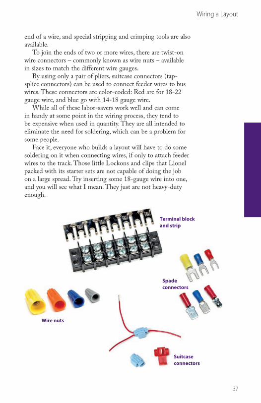
end of a wire, and special stripping and crimping tools are also available.
To join the ends of two or more wires, there are twist-on wire connectors – commonly known as wire nuts – available in sizes to match the different wire gauges.
By using only a pair of pliers, suitcase connectors (tap-splice connectors) can be used to connect feeder wires to bus wires. These connectors are color-coded: Red are for 18-22 gauge wire, and blue go with 14-18 gauge wire.
While all of these labor-savers work well and can come in handy at some point in the wiring process, they tend to be expensive when used in quantity. They are all intended to eliminate the need for soldering, which can be a problem for some people.
Face it, everyone who builds a layout will have to do some soldering on it when connecting wires, if only to attach feeder wires to the track. Those little Lockons and clips that Lionel packed with its starter sets are not capable of doing the job on a large spread. Try inserting some 18-gauge wire into one, and you will see what I mean. They just are not heavy-duty enough.
Terminal block and strip
Wire nuts
Spade connectors
Suitcase connectors
BKS-108375-SEC3.indd 37 7/15/08 1:22:45 PM

Wiri
ng a
Layo
ut
38
Soldering is an acquired skill that is perfected through prac-tice. Don’t be discouraged if you aren’t good at it the first time you try. Few people are. The following 12 guidelines will help you develop the proper techniques.
A wide range of equipment is available for every type of soldering job and every experience level. When starting out, use a basic 100-watt soldering gun or iron, whichever you prefer. The 100-watt capacity is what’s important. Anything lower takes a long time to heat the work, and anything higher might heat too fast for a beginner.
1. Buy or borrow a soldering tool and familiarize yourself with its operation. Be sure to follow the manufacturer’s instructions.
2. Buy a spool of solder and some paste or liquid flux. Get solder with a fairly thin diameter because it melts faster. For general use, solder with a standard 60:40 tin-to-lead ratio is good. Use only rosin-core solder and rosin flux for electrical work. The acid-core stuff will oxidize and corrode in time and will ruin any electrical connections made with it.
Successful soldering can be
achieved in 12 simple steps.
Successful soldering10
BKS-108375-SEC3.indd 38 7/15/08 1:22:52 PM

39
Wiring a Layout
3. Tin your new tool according to the manufacturer’s direc-tions. If your gun or iron isn’t new, tin it anyway. If it is rough or pitted from use, smooth the tip first with a fine file. Then smear some flux on the tip. Turn on the tool and heat it up. Next, run a bit of solder over the tip. The solder should adhere and look shiny. If it drips down, you used too much.
4. Practice using the gun or iron. Solder scrap wires and metal pieces together until you get the hang of the process – then practice some more.
5. Clean the surfaces of whatever you intend to solder. They must be free of rust, corrosion, oxidation, dirt, and grease. Use fine emery paper for this – even on new materials.
6. Smear flux on the areas where you want the solder to flow and adhere.
7. If possible, make a good mechanical connection first. Twist wires together as tightly as you can. Don’t rely on the solder to make the connection by itself.
8. Heat the work with your soldering tool. Apply the solder to the work, not the tool.
9. Touch the heated work with the solder. Let the solder flow until you think there is enough to hold the connection firmly.
After making a good mechanical connection, heat the work with a soldering tool, and then apply the solder.
A soldering iron can be used as well as a gun.
BKS-108375-SEC3.indd 39 7/15/08 1:23:00 PM

40
Wiring a Layout
10. Lift the soldering tool away from the work, but don’t dis-turb the work itself until you are sure the solder has hardened. You usually can see it change from a liquid to a solid state in a few seconds.
11. If you don’t get everything right the first time, reheat the connection. In its liquid state, solder is smooth and shiny. As it hardens, the shiny luster tones down a bit, but the overall appearance remains smooth and bright. If your finished work is dull, wrinkled, or grainy, you have a cold solder joint, which will give you trouble in the future. So reheat the work until the solder flows again, add a bit more solder if necessary, and wait for it to harden. Repeat this until you are satisfied with the result.
12. Be very careful as you solder. Do not touch the iron and watch out for excess solder dripping from the work. Molten metal is particularly hard on human skin and clothing.
To protect your newly soldered connection, you can cover it in several ways. One way is to wind good old electrician’s tape around the wires like a bandage. But heat-shrink tubing makes a better, more professional-looking job. It comes in a number of different diameters and can be slipped over the wires before connecting them. When you’ve finished, simply slip the tubing over the joint. The heat from a match shrinks the tubing around the connection, giving it a continuous and tight-fitting covering.
Soldering wires to track provides the
best electrical connection.
Protect soldered connections with electrician’s tape
or heat-shrink tubing.
BKS-108375-SEC3.indd 40 7/15/08 1:23:04 PM

Operating Two Trains
41
Zones of control 11In this age of digital electronics, with several highly publicized systems of command control available for model railroad lay-outs, an in-depth treatment of the various types of traditional layout wiring might seem strangely out of place.
While these new systems seem to work well, they are not for everyone. They tend to be high-tech and designed for use by the very computer literate. As such, they can be a source of confusion and frustration in the hands of hobbyists who just want to run their trains. They are also expensive.
Happily, the old tried and true systems that use trans-former technology are still around and serviceable at more reasonable prices. Both block and cab control can actually be more fun because they are hands-on systems, meaning opera-tors have to be attentive at all times.
The basic concepts involved are easy to grasp, even for those of us who aren’t rocket scientists or computer hackers:
• If power is going to the track, the train will run.• The train’s speed is determined by the amount of power
going to the track.• When power to the track is shut off, the train will stop.That’s all there is to understand. If you plan to run more
than one train, the layout must be divided into blocks, or zones of control.
Trans-former
1 2 3 4
1 2
3
4
Single-pole,single-throw
toggle switches
Block control using SPST switches
BKS-108375-SEC4.indd 41 7/15/08 1:23:12 PM

SPDT switches,one for each track block
Track block To center rail
Transformer 1
Transformer 2
To center rail
Plastic pin
To outside rail
A
U
A
UPlastic pin
Plastic pin
To outside railTrack block
42
If you eventually plan to go with one of the new electronic control systems, you’ll find that dividing your layout into blocks makes good sense anyway. With each block having its own feeder wire, the voltage drop caused by rail resistance in larger spreads will be minimized.
Blocking also makes troubleshooting easier. For example, if one block develops a short circuit, you simply turn toggle switches on and off until you locate the block with the short.
If and when you convert to the new technology, all you have to do is turn all the switches to the On position or to the same cab and then hook the electronic components to the layout as directed. The old system remains as a backup.
Block controlIf you plan to run more than one train with conventional transformer control, the layout has to be divided into zones of control, often referred to as blocks, to prevent trains from running into each other. A block is nothing more than an insulated stretch of track that is connected to its own On/Off switch or to its own separate transformer throttle. To indepen-dently slow the speed or stop the train within the block, turn the throttle down or throw the switch to the Off position. See how easy that works? Some of the larger transformers have more than one built-in throttle for this reason.
Wiring a track block
Operating Two Trains
BKS-108375-SEC4.indd 42 7/15/08 1:23:14 PM

43
Operating Two Trains
To make an insulated block, pull the steel center-rail track pins from both ends of the run of track sections you want to insulate and insert plastic or fiber pins instead (available from your hobby dealer). The two outside running rails retain their metal pins. That’s all there is to it.
How long should these blocks be? That depends on the size of the layout, the density of traffic, the average train length, and the location of yards, sidings, and stations. Blocks do not need to all be the same length, but they should be at least as long as your shortest mainline siding.
How many blocks are necessary? Again, there are only rules of thumb. Ideally, there should be at least three mainline blocks for two-train operation – more are probably better. Have at least one unoccupied block at all times; it can serve as a buffer zone between moving trains.
Generally speaking, turnouts are good locations to begin and end blocks because they usually indicate the boundaries between the main line and alternate routes, yards, and sidings. Also, you can easily spot the location of track turnouts from the control panel, even in the heat of operation.
At least one track of each passing siding should be a separate block to allow one train to wait while another passes. In fact, you may decide to make both such tracks insulated blocks, particularly if the siding is a long one. Yards and
Trans-former
Trans-former
1 2 3 4 1 2 3 4
1 2
3
4
Cab A Cab B
Cab control using SPST switches
BKS-108375-SEC4.indd 43 7/15/08 1:23:16 PM
44
Operating Two Trains
industrial complexes that are large enough to permit switch-ing operations without interfering with the main line should also be separate blocks. Finally, in most cases, you will need to insulate individual spurs. For example, each track of a locomo-tive storage facility ought to have its own switch to prevent waiting engines from moving until they are needed.
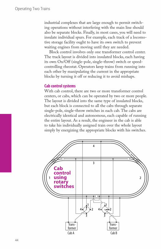
Block control involves only one transformer control center. The track layout is divided into insulated blocks, each having its own On/Off (single-pole, single-throw) switch or speed-controlling rheostat. Operators keep trains from running into each other by manipulating the current in the appropriate blocks by turning it off or reducing it to avoid mishaps.
Cab control systemsWith cab control, there are two or more transformer control centers, or cabs, which can be operated by two or more people. The layout is divided into the same type of insulated blocks, but each block is connected to all the cabs through separate single-pole, single-throw switches in each cab. The cabs are electrically identical and autonomous, each capable of running the entire layout. As a result, the engineer in the cab is able to take his individually assigned train over the whole layout simply by energizing the appropriate blocks with his switches.
Cab A Cab B
Trans-former
Trans-former
12
3
41
2
3
4
1 2
3
4
Cab control using rotary switches
BKS-108375-SEC4.indd 44 7/15/08 1:23:19 PM

45
Operating Two Trains
According to usual cab control operating procedure, an engineer may energize only two blocks at a time – the block occupied by the train and the block ahead of it. The block the train has passed through must be shut off when the one ahead is turned on because that same block could conceivably be fed by two cabs at once, which would have strange, sometimes even disastrous, consequences.
Two variations on cab control switching deserve men-tion here. The first involves the use of rotary switches instead of toggles in each cab. This system requires sharp eyes and fast reflexes on the part of the engineer, who must rotate the switch knob to the next position at the exact moment the train is moving from one block to the next.
The second variation is feasible when there are only two cabs and both are in close proximity to each other. Instead of using single-pole, single-throw On/Off switches in both cabs, an operator installs one set of single-pole, double-throw switches, with Off positions in the center for common use by both cabs. Then the engineer can select the block he wants to energize by throwing the appropriate switch in his direction.
The same procedures apply with regard to using only two blocks at a time and turning off the rest, even though both cabs couldn’t possibly feed the same block simultaneously.
Trans-former
Trans-former
1 2 3 4
1 2
3
4
Cab A Cab B
Shared double-throw toggles(A left, B right, center o)
Cab control using SPDT switches
BKS-108375-SEC4.indd 45 7/15/08 1:23:21 PM

46
Operating Two Trains
There is often some fumbling and confusion at the shared portion of the control panel as both engineers try to manipu-late the same row of toggle switches. It helps if one of them is right-handed and the other is left-handed.
Individual transformers for each blockOne of the most creative control systems is the embodiment of simplicity and economy. It’s a variation on conventional block control that uses a battery of small transformers, one for each block, instead of one large transformer and a series of toggle switches.
With it, each block has its own individual speed control, whistle control, and reversing button, so one train can be slowed down realistically to prevent an accident with another rather than going through the equivalent of an emergency stop whenever a switch is thrown.
Onboard train whistles and horns can be activated individu-ally, instead of having them all blow at once, with the resulting slow down of every train on the layout. Because each block has its own reversing control, the E-unit sequence reverse mecha-nisms need not be locked into the Forward Only position as they usually are with conventional block and cab control.
Each transformer powers one block of track, nothing more. Other small transformers can be used for fixed-voltage acces-sory circuits and other electrical requirements. Often, several
Transformers
1 2 3 4
1 2
3
4
Individual transformers for each block
BKS-108375-SEC4.indd 46 7/15/08 1:23:23 PM

47
Operating Two Trains
fixed-voltage values are needed for different accessories. Set them up on their own transformer circuits and forget them.
Besides the versatility this system offers, the dollar savings can be substantial. Small transformers, those rated at 100 watts and under, aren’t highly prized by operators or dealers, so they can often be picked up at very reasonable prices. And the supply is immense: Lionel made them by the millions, and most of them still work. Model 1063 and the earlier metal-cased 1042 transformers fit well in this application. Both are rated at 75 watts, feature whistle controls, and can handle 3 to 4 amps – enough to handle one average train on one block of track.
These small transformers don’t have to be of the same type or vintage to work, although there is a certain visual appeal to a lineup of similar units. Their wattage ratings should be close to each other, so there won’t be a big difference in energy level as the train moves from block to block.
Preserving the sequence-reverse functionThe usual procedure when operating trains on block or cab-controlled layouts is to lock out the E-unit sequence reversing mechanisms and run all the locomotives in the Forward Only mode. That works well, but it limits operating potential.
The scheme that Lionel recommended to preserve the reversing feature of the locomotives, even though insulated blocks are used, is to jump the insulating pin going into each block with a 10-ohm, 25-watt adjustable resistor.
Another and perhaps preferable way to put such a resistor into the circuit would be across the toggle switch terminals.
With either installation, you can then adjust the resistor to permit just enough current to leak into the insulated block to keep the reverse unit’s solenoid energized, although not enough to operate the locomotive’s motor.
Making this adjustment on the resistor can be tricky, but it is worth the effort. Adjustable resistors of this kind can be obtained from industrial electrical or electronics supply companies.
Jumping the insulating pin with a resistor
Adjustableresistor
Fiber pin
Adjustableresistor
Totrack
Totransformer
Toggleswitch
Using a resistor across a toggle switch
BKS-108375-SEC4.indd 47 7/15/08 1:23:25 PM

Oper
atin
g Tw
o Tra
ins
48
It was the dream of every boy who grew up during the Golden Age of Toy Trains to be able to automatically run two trains on the same track without danger of a collision. Unfortunately, all we had to accomplish such a feat back then was the notoriously unreliable no. 153C contactor, which was activated by the weight of a passing train and was in constant need of adjustment. After a few bad rear-enders, most of us just gave up on the idea.
A train control system prevents
collisions while operating two trains.
Collision prevention12
SPST relay(normally closed)
Normally closed
To transformer(12-14 volt tap power)
Directionof travel
Stop section(about 3 feet)
Trip section(4 to 5 feet)
Fiber pinInsulated outside railFiber pinFiber pin
BKS-108375-SEC4.indd 48 7/15/08 1:23:34 PM

49
Operating Two Trains
What we needed, in addition to the center-rail insulated stop section that we already had with the no. 153C contactor, was a positive device to shut off the power to the stop section when the second train was getting too close to the first one. We needed a relay!
The two systems described here use relays, positively activated by insulated running rails that can’t get out of adjustment. They both operate on the same principle, but the second system is a bit more elaborate.
System OneThe key is a normally closed single-pole, single-throw (SPST) relay that controls the distribution of power to the stop sec-tion, with its center rail insulated from the remainder of the layout. The stop section doesn’t have to be very long. Unless you are a chronic high-baller, you need only about a three-foot section to stop a locomotive and prevent it from coasting through the dead block.
The trip section, set off by two insulated track pins in an insulated stretch of outer rail, is usually only a few track sec-tions ahead of the stop section. It should be long enough to prevent a stopped train from starting up before there is a safe distance between the trains. While the trip section’s length will depend to some degree on the size of the layout, a mini-mum of four to five feet is recommended.
SPST relay(normally closed)
Normally closed
To transformer(12-14 volt tap power)
Directionof travel
Stop section(about 3 feet)
Trip section(4 to 5 feet)
Fiber pinInsulated outside railFiber pinFiber pin
System One
BKS-108375-SEC4.indd 49 7/15/08 1:23:36 PM

50
Operating Two Trains
System TwoThis system, which is preferred by many operators, is nearly identical to System One, except that a different relay allows for multiple train control and the realistic use of track signals.
A double-pole, double-throw (DPDT) relay not only turns the track power in the stop section on and off but simultane-ously allows an electrical path to switch from one light bulb to another. So you can make a red signal change to green at the same time a train powers up and leaves the stop section.
Among the two-bulb accessories that can use this system are block signals (Lionel postwar nos. 153, 163, and 353), signal bridges (no. 450), gantry signals (no. 452), and dwarf signals (no. 148).
If you have a large layout, what’s great about using these systems is that you can install as many blocks as you need to prevent rear-end collisions. Keep in mind that with this system you have the added benefit of an impressive light show in each block area.
Of course, with both of these systems, locomotive reverse units are locked into the Forward Only mode. For those who want to preserve the reversing function, there is a way around this with adjustable resistors in each block.
DPDT relay
To transformer(12-14 volt tap power)
7
82 4 6
1 3 5
Directionof travel
Stop section(about 3 feet)
Trip section(4 to 5 feet)
Fiber pinFiber pinFiber pin
To transformer(common)
Insulated outside rail
System Two
BKS-108375-SEC4.indd 50 7/15/08 1:23:38 PM

51
Operating Two Trains
DPDT relay
To transformer(12-14 volt tap power)
7
82 4 6
1 3 5
Directionof travel
Stop section(about 3 feet)
Trip section(4 to 5 feet)
Fiber pinFiber pinFiber pin
To transformer(common)
Insulated outside rail
Relay
Rectifier
AC and DC relaysRelays are common in toy train control, but over the years, a shift occurred from alternating current relays to today’s direct current relays.
The two systems described are designed for use with relays having a 12-volt AC coil, once a staple for automatic block control. If you have 12-volt AC relays, or know where to find some, by all means use them, as they have become scarce.
DC relays are plentiful and may be substituted with good results. However, to accommodate the DC coils, the AC current from the transformer must first be converted to DC. The simplest way to do this is with a full-wave bridge rectifier (available at many electronics stores).
The rectifier should have a voltage rating at, or above, the 12 volts needed for the coil and enough amperage capacity in the contacts to handle a multi-train layout. A minimum of 5 amps is recommended.
Full-wave bridge rectifiers have four terminals – pins, wires, or solder lugs – on them. The two AC input terminals are either labeled AC or designated with a sine wave (~). Con-nect these terminals to the transformer, or in this case, to the transformer and the insulated track section.
The two DC outputs are labeled + and -. In this applica-tion, the plus and minus designations make no difference. Just wire one of them to one end of the relay coil and wire the other one to the other end. That’s it.
The wiring diagram below shows how these rectifiers should be wired into the circuit ahead of the DC relay coil.
AC connections are interchangeable.One connects to the hot terminal of an AC transformer (or center rail of the track) and the other to the outsidetrack rail (ground) when using aninsulated section of rail to triggeran accessory.
Positive connectsto relay
Negative connects to relay
Full-wave bridge rectier
Positive and negativeterminals to power the internal workingsof the DC relay
12- or 18-volt DC relay
(AC)
(AC)
(–)
(+)
Converting AC current from a transformer to DC
BKS-108375-SEC4.indd 51 7/15/08 1:23:43 PM

Oper
atin
g Tw
o Tra
ins
52
The automatic non-derailing feature, which Lionel pioneered and incorporated into all of its turnouts (and adopted by other manufacturers), worked on the principle of the insulated run-ning rail. A short section of rail on both routes was insulated so that, if the turnout was thrown against an approaching train, the wheels and axles of that train would bridge the rails, complete the electrical circuit, and, in the last second, throw the turnout in the right direction, so the train would not derail.
The non-derailing feature can be used in a system in which the train itself automatically selects different routes. This is accomplished by wiring two or more turnouts together as shown in the sample layouts on the next two pages.
This automated system can be disabled by inserting a double-pole, single-throw (DPST) switch in the wiring between each pair of linked turnouts. When switched off, the turnouts can be controlled individually by the operator. It is not necessary to unhook the normal turnout controllers when wiring in the automated system.
Wiring two or more turnouts
together can allow a train to select its route automatically.
Automatic route selection13
DPST switch disabling the automated system
BKS-108375-SEC4.indd 52 7/15/08 1:23:49 PM

53
Operating Two Trains
Y
X
B
A
Distance from X to Y representsmaximum train length
One pair of turnouts, one 90-degree crossingTwo passes to cover layoutTurnouts thrown in unison: green-green, red-red
D
C
B
A
Two pairs of turnoutsFour passes to cover layoutTurnouts thrown in opposition to each other: green-red, red-green
Basic two-oval layout
Interconnected two-oval layout
Sample layoutsThe following four simple layouts use automatic train control and illustrate the principles involved, which you can apply to your own layout.
BKS-108375-SEC4.indd 53 7/15/08 1:23:51 PM

54
Operating Two Trains
C
DB
A
Two pair of turnouts, one 90-degree crossingFour passes to cover layoutTurnouts thrown in opposition to each other: green-red, red-green
C D
BA
½ S ½ S½ C ½ C
Two pair of turnouts, one 45-degree crossingFour passes to cover layoutTurnouts thrown in opposition to each other: green-red, red-greenSome half straight and half curve sections required
Christmas tree layout
Double cross layout
BKS-108375-SEC4.indd 54 7/15/08 1:23:54 PM

Using Accessories and Controllers
55
14Train-activated accessories
For decades, Lionel train-activated accessories were sold with special contactors that made them operate. There were four different ones.
145C and 153C were adjustable, spring-loaded switches that fit under the track and responded to the weight of the passing train. The others, 154C and 1045C, had insulated contact plates that snapped into place over one of the two running rails. The metal wheels and axles of the passing train momentarily completed an electrical circuit between the other running rail and the insulated plate.
All four worked well enough to keep a kid who ran his trains around the Christmas tree or on the rec room floor happy. However, for permanent model railroad layouts, they fell somewhat short. The spring-loaded contactors were notorious for working themselves out of adjustment regularly, while the contact-plate models needed help in the realism department.
Lionel accessories were operated with four different contactors.
BKS-108375-SEC5.indd 55 7/15/08 1:24:08 PM
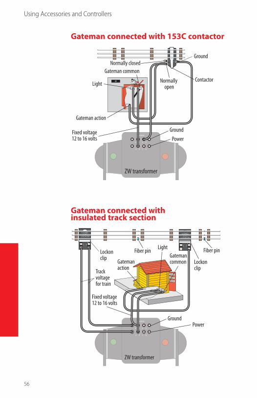
1
23
C O M M O N
U U U U
A B C D
Ground
Gateman common
Ground
Power
ZW transformer
Fixed voltage12 to 16 volts
Gateman action
LightContactorNormally
open
Normally closed
C O M M O N
U U U U
A B C D
Ground
Gatemanaction
Gatemancommon
Power
ZW transformer
Fixed voltage12 to 16 volts
Lockon clip
Lockon clipTrack
voltagefor train
Fiber pin Fiber pinLight
56
Gateman connected with 153C contactor
Gateman connected with insulated track section
Using Accessories and Controllers
BKS-108375-SEC5.indd 56 7/15/08 1:24:11 PM

57
Using Accessories and Controllers
145C contactorThis was the most common spring-loaded Lionel contactor. It functioned as a simple single-pole, single-throw switch. The weight of the train overhead forced the contacts together and completed the electrical circuit to the accessory. The no. 145C came with the following accessories:
45 and 145 Gateman140 Banjo Signal151 Semaphore155 Ringing Signal252 Crossing Gate262 Highway Crossing Signal
153C contactorIntended to operate two-light (red and green) block signals, the no. 153C was a single-pole double-throw switch, with the normally closed position connected to the green light. With the weight of the passing train, the green light connection would be opened, and the connection with the red light tem-porarily closed. When the train passed, the contactor spring would return it to normal, and the signal would again show green.
The 153C came with the 153, 163, and 353 two-light block signals. Many operators also used it to automate the no. 148 Dwarf Signal.
By using a center-rail insulated block at the signal, and connecting its power to the green light terminal on the con-tactor, a basic form of automatic two-train control could be achieved.
154C contactorThis specialized insulated-plate contactor was packed only with the no. 154 Highway Flashing Signal. The plate was divided into two sections, corresponding to the two lights on the signal. Contact made by the wheels of the passing train would cause the lights to blink intermittently in a charming, albeit not particularly realistic, way.
1045C contactorThis also was a one-accessory contactor. It came with the no. 1045 Flagman. Contact made by the train wheels would make the flagman raise his warning flag. It would drop in a staccato motion after each wheel set passed.
BKS-108375-SEC5.indd 57 7/15/08 1:24:13 PM

58
Using Accessories and Controllers
C O M M O N
U U U U
A B C D
1
23
Ground
Normally closedNormally open
Power
Contactor
Lockon clip
ZW transformer Fixed voltage - 12 to 16 volts
Track voltagefor train
Crossing gate
Crossing gate connected with insulated track section
C O M M O N
U U U U
A B C D
Fiber pin Insulated railof outer track
GroundPower
Lockon clipLockon clip
Track voltagefor train
ZW transformer
Fixed voltage - 12 to 16 volts
Fiber pin
Crossing gate
Crossing gate connected with 153C contactor
BKS-108375-SEC5.indd 58 7/15/08 1:24:15 PM

59
Using Accessories and Controllers
C O M M O N
U U U U
A B C D
Fiber pin Insulated railof outer track
GroundPower
Lockon clipLockon clip
Track voltagefor train
ZW transformer
Fixed voltage - 12 to 16 volts
Fiber pin
Crossing gate
Insulated running railsA far better way to activate accessories is by connecting them to an insulated running rail and allowing the metal train wheels and axles complete the electrical circuit. This method does everything the 145C, 154C, and 1045C can do and probably even more. Here are some additional advantages:
• Insulated rails never go out of adjustment. Of course, they have to be kept reasonably clean.
• There is positive action throughout the length of the train. They work just as well from the loco to the caboose in spite of weight discrepancies.
• Any number of insulated track sections can be used in a run to provide longer approaches to crossing gates, signals, and the like.
• Loose track sections do not bob up and down. They can be securely fastened and even ballasted.
• While unsightly contactor mechanisms stick out, acces-sory wires can be discretely soldered in place.
To wire an accessory to be activated by an insulated run-ning rail, attach one wire to the insulated rail and the other to the center rail or a fixed-voltage power source.
You can buy insulated running rail sections or make your own. Lionel and others offer ready-made straight sections, but you can save money by making them yourself. It’s easy to do and you can put insulated sections anywhere, even on curves.
Begin by bending the tie clips upward and removing one of the running rails from the section to be insulated. Then take the fiber center-rail insulators from a discarded track section and slip them on the loose rail. (Cardboard or electrical tape may be used instead.) Crimp it back in place. Put plastic or fiber insulating pins into both ends of the rail to isolate it electrically from the rest of the track. That’s all there is to it.
If you make your own, you can get creative. For instance, instead of using 154C and 1045C contactors to operate the highway flasher and the flagman, which require short, inter-mittent contacts, you can insulate short pieces of rail within a normal section and wire appropriately. More ties should be added to this track to strengthen the reconstruction.
BKS-108375-SEC5.indd 59 7/15/08 1:24:17 PM

60
Using Accessories and Controllers
To insulate a running rail, use a screwdriver to bend the tie clip and remove the
running rail.
Masking tape can keep the insulation in
place when replacing the rail.
Replace the rail, crimp it in place, and put
an insulating pin into both ends.
BKS-108375-SEC5.indd 60 7/15/08 1:24:29 PM

61
Using Accessories and Controllers
154 AutomaticHighway SignalPlastic
insulatingpinsCardboard center
rail insulators
Cardboard centerrail insulators
Insulating short pieces of rail
That takes care of replacing the 145C, 154C, and 1045C contactors. Replacing the 153C contactor requires the use of a relay in addition to the insulated rail.
Accessory operating voltagesThe list of operating voltages for Lionel postwar accessories on page 62 contains voltages that were specified in official service literature. For the rest, we can only guess or, better yet, experiment with to find a happy (or at least a working) medium of some kind.
Lionel uses the word variable when describing these input voltages for some accessories. For the 350 Transfer Table and 375 Turntable, the voltage level (the speed of operation) is probably a matter of personal operator preference. The 356 Freight Station, 362 Barrel Loader, 464 Lumber Mill, and 494 Rotary Beacon are powered by notoriously hard-to-adjust vibration motors. Probably because each motor has characteristics that make it unique, the optimum input voltage can’t be generalized and must be determined by experimenting.
Some operators connect small, individual starter-set transformers to each vibration-motor accessory, so they can adjust the throttles to provide the optimum individual voltage level.
It is easy to see why some larger, accessory-laden layouts often have as many as three different fixed-voltage accessory buses. The three voltage ranges commonly used are 10-12, 14-16, and 18-20. The first two accommodate most of the listed accessories, while the third is reserved for turnout motors.
BKS-108375-SEC5.indd 61 7/15/08 1:24:31 PM

62
Using Accessories and Controllers
Operating voltages for Lionel postwar accessoriesNumber Accessory Input voltage
45 Automatic Gateman 12
75 Tear Drop Lamp 14
97 Coal Elevator 12-16
125 Whistling Station 10-14
128 Animated Newsstand 11-13
138 Water Tower 10-14
140 Banjo Signal 12-16
145 Automatic Gateman 12-14
153 Block Signal 12-14
161 Mail Bag Pickup 10-14
164 Lumber Loader 12-16
165 Magnet Crane 10-15
175 Rocket Launcher 9-12
182 Magnet Crane 12-16
193 Flashing Tower 12-16
195 Floodlight Tower 12-14
252 Crossing Gate 10-14
264 Fork Lift Platform 9-14
313 Bascule Bridge 14 (approximate)
342 Culvert Pipe Loader 9-14
345 Culvert Pipe Unloader 9-14
350 Transfer Table Variable
356 Freight Station Variable
362 Barrel Loader Variable
364 Lumber Loader 12-14
375 Turntable Variable
395 Floodlight Tower 12-14
397 Coal Loader 12-15
410 Billboard Blinker 12-16
415 Fueling Station 12-16
450 Signal Bridge 12-16
455 Oil Derrick 12-14
456 Coal Ramp 12-14
464 Lumber Mill Variable
494 Rotary Beacon Variable
BKS-108375-SEC5.indd 62 7/15/08 1:24:34 PM

Using Accessories and Controllers
63
15Ganged controllersGanging controllers, hooking up one controller to activate two or more similar remote controlled devices, is usually done for convenience or for saving valuable space on the control panel. Toy train control boxes were designed for around-the-tree or living-room-floor operations without any consideration of size.
While I have seen accessory controllers ganged in a mul-titude of innovative ways, and for various good reasons, the two most common and logical applications are with uncouple/unload track sections and remote control turnouts.
UCS remote control sectionsSince the electromagnet (uncouple) and the control rails (unload) on a UCS remote control track section work only when there is a coupler or an operating car in place over them, it doesn’t matter if several are ganged together on one controller.
This particularly makes sense in yards or other locations where several UCS remote sections are in close proximity to each other – within one frame of vision for the operator. I’ve seen large layouts with four or five of them wired together with excellent results.
Linking two or more UCS remote control track sections is quite simple. Connect the four wires from the controller cable to the numbered terminals (1, 2, 3, 4) on the track as usual.
Then run four more wires from each of the numbered terminals on the first section to the like-numbered terminals on the second section.
For a third section, do the same thing, using the second section as your starting point. Continue on for as many sec-tions as you wish.
Remote control turnoutsFor convenience, the throw mechanisms of two (or more) remote control turnouts may also be ganged for operation by one controller. Of course, this is practical only in situations where the turnouts always need to be thrown at the same time and in the same relationship to each other.
The most obvious examples are on crossovers between tracks or on semi-automated layouts where the position of one key turnout determines the route the train is to take.
BKS-108375-SEC5.indd 63 7/15/08 1:24:35 PM

64
Uncouple UnloadUncouple Unload
Controller
Controller used as an override for the system Controller
Ganged UCS tracks
Crossover
Automatic route selection with non-derailing turnouts
How to wire ganged UCS
tracks is shown here.
Using Accessories and Controllers
BKS-108375-SEC5.indd 64 7/15/08 1:24:40 PM
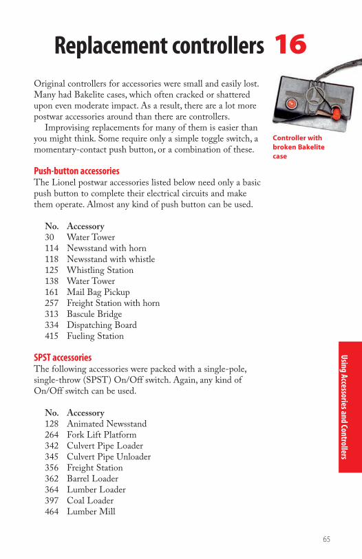
Using Accessories and Controllers
65
Replacement controllers 16Original controllers for accessories were small and easily lost. Many had Bakelite cases, which often cracked or shattered upon even moderate impact. As a result, there are a lot more postwar accessories around than there are controllers.
Improvising replacements for many of them is easier than you might think. Some require only a simple toggle switch, a momentary-contact push button, or a combination of these.
Push-button accessoriesThe Lionel postwar accessories listed below need only a basic push button to complete their electrical circuits and make them operate. Almost any kind of push button can be used.
No. Accessory30 Water Tower114 Newsstand with horn118 Newsstand with whistle125 Whistling Station138 Water Tower161 Mail Bag Pickup257 Freight Station with horn313 Bascule Bridge334 Dispatching Board415 Fueling Station
SPST accessoriesThe following accessories were packed with a single-pole, single-throw (SPST) On/Off switch. Again, any kind of On/Off switch can be used.
No. Accessory128 Animated Newsstand264 Fork Lift Platform342 Culvert Pipe Loader345 Culvert Pipe Unloader356 Freight Station362 Barrel Loader364 Lumber Loader397 Coal Loader464 Lumber Mill
Controller with broken Bakelite case
BKS-108375-SEC5.indd 65 7/15/08 1:24:43 PM

Usin
g Ac
cess
orie
s and
Cont
rolle
rs
66
Other controllersThe no. 97 Coal Elevator and the no. 164 Lumber Loader had both push buttons and SPST switches on their control-lers. The three lead wires from the controllers were connected to numbered terminals on the accessories. The controllers, and the way their functions were wired, are identical on both.
No. 97 Coal Loader controller
To transformer (12-16 volts)
Push button
SPST toggle switch
This no. 97 Coal Elevator has
been wired with a replacement
controller.
Using Accessories and Controllers
BKS-108375-SEC5.indd 66 7/15/08 1:24:53 PM

67
The controller for the 456C Coal Ramp controller used push buttons to operate its uncouple, unload, and release functions.
No. 456C Coal Ramp controllerTerminal panel Release Unload Uncouple
12-14 volts (track furnishes the ground)
Release
Unload
Uncouple
The controller for the 456C Coal Ramp was unique to the accessory. Three push buttons handled the uncouple, unload, and release functions. To fabricate one, start by mounting three SPST momentary-contact push-button switches in a row. Each switch has two terminals. Wire all three switches together, using one terminal on each. Run three wires from the remaining terminals to the three posts on the coal ramp. Connect a single wire from the three interconnected terminals to a fixed-voltage post on your transformer (12-14 volts are recommended). The track serves as the ground return.
Coal ramp replacement controller
Using Accessories and Controllers
BKS-108375-SEC5.indd 67 7/15/08 1:25:00 PM

68
Using Accessories and Controllers
The 497C Coaling Station came with a four-function controller that used two levers for activation. While it would be difficult to improvise such a controller, we found that sub-stituting four SPST momentary-contact push buttons would yield the same results.
The 497C Coaling Station
controller employed two
levers to operate four functions.
14 volts (track furnishes the ground)
Terminal strips on motor Load Up
Down
Dump
No. 497C Coal Station controller
BKS-108375-SEC5.indd 68 7/15/08 1:25:13 PM

69
Using Accessories and Controllers
022 turnoutsThe ubiquitous Lionel 022 track turnouts, and many similar O gauge products that followed the pattern over the years, came equipped with impressive lever-action controllers having red and green indicator lights on them.
If you can forego the indicator lights, a functional replacement can be fabricated with a momentary-contact, single-pole, double-throw (SPDT) toggle switch that has a center Off position. This will work just like the lever in the original controller.
If you can’t find a toggle switch with all of these specifica-tions, any SPDT with a center Off position can be substi-tuted. But you’ll have to remember to manually return the switch to the Off position immediately after the turnout is thrown. Otherwise, the non-derailing feature won’t work, and the solenoid coils in the unit will eventually burn out.
Dwarf signalThe versatile controller for the 148 Dwarf Signal was nothing more than an SPDT switch that could be wired in several ways:
• To change the signal light from green to red.
• To interlock the signal with an insulated track block to stop the train when the lights change.
• To be used with other signals and insulated blocks to pro-vide a system of multiple train control for the entire layout.
Transformeraccessory power
Common
SPDT switch
Remote controltrack turnout
Replacement turnout controller
BKS-108375-SEC5.indd 69 7/15/08 1:25:15 PM

70
Using Accessories and Controllers
UCS controllersThe five-rail UCS remote control track section serves as both an uncoupling and unloading location for Lionel postwar roll-ing stock. The uncoupling function is handled by an electro-magnet in the center of the section. The unloading function for operating freight cars is controlled by two pairs of rails, right and left of the magnet.
The two-button UCS controller contains a four-layer wafer switch that looks dauntingly complicated. It isn’t really, but to replace it, you need an SPST switch and a DPST momentary-contact push button. The push button might be hard to find at your local electronics store.
A quite satisfactory alternative can be made by using two SPST momentary-contact push-button switches, wired as shown above.
This alternative is a lot easier to wire, but it requires a departure from the operational norm. The uncoupling button is used by itself, but to energize the unloading function, both buttons must be pushed simultaneously.
All things considered, the best option might be to find a used UCS controller, still in working condition, at a swap meet or in a hobby shop clearance bin. They are by no means scarce commodities since Lionel made millions of them over the years.
Almost any simple toggle or push-button switches of the right configurations can be used when improvising replacement controllers for Lionel postwar accessories. While the current drain for most accessories is less than for trains, switches with at least 3- to 5-amp ratings should be used throughout.
If your layout has a control panel, your replacement control-lers can be built right in. If not, they can be housed in small metal or plastic boxes. If you are good with sheet metal, you can even bend your own. Improvise – that’s the name of the game.
To unload, both buttons must be pushed simultaneously
SPST push-button switchesUncouple
Numbered terminals on track section
1 2 3 4UCS wiring
BKS-108375-SEC5.indd 70 7/15/08 1:25:17 PM

Using Accessories and Controllers
71
To unload, both buttons must be pushed simultaneously
SPST push-button switchesUncouple
Numbered terminals on track section
1 2 3 4 17Quick fixesThis chapter covers several miscellaneous situations that you might encounter when wiring your layout.
Wiring two intersecting independent routesLionel crossings, often referred to as crossovers, were constructed with electrical continuity maintained on both intersecting routes. They must be modified if two independently controlled routes are expected to cross over each other. It is a fairly easy job, involving removal of the sheet-metal stamping on the underside of the crossing and replacing it with two wires.
First, bend the fingers holding the sheet-metal stamping just enough so the stamping can be removed. Then, bend the fingers back into position against the insulators, so the rails are again seated firmly in place.
Solder short pieces of 18-gauge wire, basically creating electri-cal bridges that link the linear center rails while keeping the intersecting routes electrically isolated from each other.
Fixed voltage for remote control track sectionsUsing fixed voltage on UCS or 6019 remote control track sections improves performance and allows them to function even when track power is off. The simple conversion involves only one wire.
To change a UCS track section to fixed-voltage operation, unhook the number 3 wire in the cable (counting from the left) from its terminal on the track section and connect it to a 15-volt accessory bus or directly to a similar post on the transformer.
For some reason, Lionel designed the 027 tracks differently, so with an 027 gauge 6019 remote control track, disconnect the number 4 wire instead.
Wire bridges link a crossing’s center rails and keep intersecting routes isolated.
Coil
GroundLeft control rails
Right controlrails and coil
Fixedvoltage
Transformer
UCS track wired for fixed voltage
BKS-108375-SEC5.indd 71 7/15/08 1:25:21 PM

72
Warning lights for hidden trackageNo matter how well planned and designed, there always seems to be a few blind spots on every layout that could be a problem – the inside of a long tunnel, behind a scenic back-drop, or some other place where the track can’t be seen from the operator’s control position.
Dick Christianson had some troublesome ones on his long gone, but probably never-to-be-forgotten by those who saw it, Lionel Lines/Santa Fe layout (featured in Build a Better Toy Train Layout). He and John Grams solved the
3 sections 2 sections
To xed voltage(or track voltage)
RedYellow
Insulated track sections used for warning lights on a hidden spur
Using Accessories and Controllers
Wall
To xed ortrack voltage
Fiber pins
Track with insulated outside rail Use plastic Lionelbumper that won’tground rails together
Hidden siding
Wiring diagram for warning lights
The lights in the tower indicate train position.
BKS-108375-SEC5.indd 72 7/15/08 1:25:29 PM

73
Using Accessories and Controllers
visibility problems with a series of colored warning lights on the control panels and elsewhere. What they did can be a guide to solving similar situations on your model railroad.
The warning lights were all connected to a fixed-voltage circuit, and in the first two cases that follow, were triggered by an insulated running rail.
The freight yard lead, which also doubled as a switchback, ran under a bridge and then disappeared behind a backdrop for about 10 feet before ending. Using two separate runs of insulated track sections and red and yellow lights, the operator can chart the progress of the hidden train.
The yellow caution light went on to indicate that the train was five track sections (about 50 inches) from the end of the line. The red light meant the train was only two sec-tions (20 inches) away, so it was time to stop.
Dick decided to mount the two lights in the control tower at the head of the yard. In plain sight to all, this tower actually served a function on the layout.
A long, behind-the-backdrop passing siding, which was a convenient place to store a full-length train, posed an even greater problem. There was no way of seeing when a train was entering the siding or when it was leaving.
A four-light indicator on the control panel solved it: One siding was green, and the other was red. Short insulated rails at both ends of the two routes would make the control panel lights blink, indicating the train’s position.
To guard against mishaps, a single-pole, double-throw switch routed the track power to one siding or to the other.
The passenger terminal’s lead track disappears into a tunnel.
BKS-108375-SEC5.indd 73 7/15/08 1:25:36 PM

74
Using Accessories and Controllers
To track voltageSPDT switch
Fixed voltage
Green
Red
Fixed-voltageplug
022 switch
To switchcontroller
153 Block Signal
Indicator lights wired with short insulated rails
Using a block signal as a remote switch position indicator
The lead track from the passenger terminal disappeared into a tunnel and emerged at a mainline turnout on the other side of a hill. Dick and John rigged a no. 153 Block Signal to indicate red when the turnout was set for the main line and green when it was thrown to allow a train to leave the station and enter the high iron.
They ran three wires from the signal’s terminals to the three terminals on the turnout mechanism. Then, the sliding contacts that changed the controller’s indication from red to green changed the signal bulbs the same way. To get a reverse indication, simply switch the two outer wires leading to the block signal.
BKS-108375-SEC5.indd 74 7/15/08 1:25:39 PM

Maintaining and M
onitoring a Layout
75
You can probably live without a multimeter, but once you get used to having one, you’ll wonder why you didn’t buy it long ago. A multimeter is particularly useful if you have an operat-ing layout with blocks, feeders, turnouts, lights, and accessories to maintain or if you do your own service and repair work on rolling stock.
Common uses for a multimeter on a layout include• Regulating track voltage• Setting fixed voltages for accessories and turnouts• Finding voltage drops in trackwork and wiring• Tracing continuity of wires and connections in circuits• Checking the function of electrical switch contacts• Locating short circuits in track, wiring, and accessories• Phasing transformers
Whether you buy an analog or digital meter makes little difference. Some people want to see a numerical digital readout on a screen, while others prefer the classic look of an analog meter, with its needle sweeping across an arc of gradu-ated scales. Both work equally well. All you really need is the most basic and inexpensive model you can find. Whichever multimeter you use, remember to read the instruction booklet carefully before using your meter and always turn your meter to the Off position when not in use.
Multimeters 18
When using an analog multimeter on lower voltages, the 15V ACV position provides more precise readings.
BKS-108375-SEC6.indd 75 7/15/08 1:33:40 PM

76
Measuring voltageFind the most appropriate AC voltage scale available for toy train use. That would be the closest upper meter range higher than the voltage you want to measure. The general range for toy trains is zero to about 25 volts (AC). If you select a lower meter range, you might damage the instrument.
Using the pictured meters as examples, the digital model should be set on the 200V ACV position. This will provide the most accurate direct numerical readout on the screen.
The analog model has a convenient 150V ACV position. To use this, you simply multiply the reading shown on the bottom 15-volt scale by 10. For a more precise reading on lower voltages, you may use the 15V ACV position but make sure the transformer output voltage is kept below that level.
A digital multimeter is being used to
measure track voltage.
Maintaining and Monitoring a Layout
BKS-108375-SEC6.indd 76 7/15/08 1:33:50 PM

77
Maintaining and Monitoring a Layout
This analog multimeter is set to measure ohms of resistance.
Checking electrical circuit continuityTo measure circuit continuity, or lack thereof, use the meter position that indicates ohms (Ω) of resistance.
The analog meter has only one of these, lK (l,000 ohms). The digital meter has five range choices. While they all will work, the 2,000 ohm (2K Ω) position is best because it pro-vides a very stable reading in this application.
Full circuit continuity is indicated by a reading of zero on the ohms scale. If you experience poor or intermittent con-tinuity, which can be caused by a bad connection or loose or dirty contacts, you will get a reading other than a steady zero.
Finding the source of a short circuit is easy with a multi-meter. You’ll find continuity where there should be none.
BKS-108375-SEC6.indd 77 7/15/08 1:33:57 PM

Mai
ntai
ning
and
Mon
itorin
g a L
ayou
t
78
Many serious model railroaders have installed voltage and amperage meters on their control panels. While not absolutely essential to operations, they provide an added dimension of sophistication, and operators, knowing their track power is constantly being monitored, gain a sense of control.
What the meters doA volt meter measures the amount of voltage (output) being delivered to the tracks, while an amp meter shows the amount of amperage (current) the locomotive is drawing at any given moment.
The most practical application for the volt meter is in determining approximate train speed. While there is no actual readout in scale miles per hour – voltage requirements can vary quite a bit from loco to loco – the meter will at least give you a ballpark indication. That in itself may keep you from highballing the train too fast for the curves.
The amp meter helps keep tabs on the condition of your engines. A locomotive that draws an excessive amount of amperage may be in need of repair or routine lubrication, cleaning, and maintenance.
And an amp meter will always indicate an overload or a short circuit long before the transformer’s circuit breaker kicks in.
When installed on a control panel, amp
and volt meters provide
continuous monitoring.
Amp and volt meters19
A volt meter can be used to indicate approximate train speed.
An amp meter helps monitor engine condition and indicates transformer overload.
BKS-108375-SEC6.indd 78 7/15/08 1:34:05 PM

79
Maintaining and Monitoring a Layout
Selecting the right metersWhether you select classic analog meters, with their needles that sweep in graceful arcs across the scales, or new digital models that present numerical readings, often down to several decimal places, makes absolutely no difference. In this applica-tion, it simply is a matter of personal preference.
It is important to buy meters that register in the proper ranges. That means zero to at least 25 or 30 volts for a volt meter, and zero to about 10 amps for an amp meter. Broader ranges tend to obscure the accuracy of the readings, particu-larly on analog instruments.
Also, both must be AC (alternating current) meters. Many of the meters found in electronics stores today are intended for use with DC (direct current), and they won’t work with toy trains. To find the correct ones, you may have to shop around or order them from electronics suppliers.
If you are using a Lionel ZW transformer, and don’t mind paying a bit more for convenience, Lionel sells a pair of digital meters that fit right on the transformer.
InstallationIdeally, a set of these meters should be installed for each transformer-powered circuit, but most operators settle for one set to monitor the track circuit only.
Hooking up voltage and amperage meters is really a simple job. As shown above, the volt meter is connected across the two transformer terminals being used for the track circuit.
The amp meter is connected in line (series) with the center-rail leg of the track circuit.
Transformer
AC volt meter
Common
Power TrackTransformer
AC amp meter
Common
TrackPower
Connecting a volt meter Connecting an amp meter
BKS-108375-SEC6.indd 79 7/15/08 1:34:07 PM

Control rails
Ground
Contact spring from switch frog rail
Ground
Rotating lamp
Booster pin
Coil BCoil AGround
Red lamp
Green lampConnecting strap pin
Mai
ntai
ning
and
Mon
itorin
g a L
ayou
t
80
022 turnouts20
Circuit diagram of a 022 turnout and controller
Lionel’s 022 turnout are
complex devices that contain
many moving parts.
The first choice of operators for generations, Lionel’s 022 turnouts were manufactured from the late 1930s to the late 1960s, revived and renumbered 5132/5133 in 1980, and made for another 14 years. Lionel’s O-72 gauge turnouts share many 022 parts, including the mechanisms, so many of these tips also apply to them.
Well designed and solidly constructed from the start, these turnouts are complex electro-mechanical devices with many moving parts. Much could go wrong, but it usually doesn’t as long as they are kept clean and well-maintained.
BKS-108375-SEC6.indd 80 7/30/08 1:02:49 PM

81
Maintaining and Monitoring a Layout
Control/Contact Cleaner may also be known as TV Tuner Control Cleaner.
While repair techniques are beyond the scope of this book, here are some routine maintenance tips that will keep your 022s on your layout and out of the shop.
Clean and tune your 022 turnouts as needed, either when the action becomes erratic or sluggish or after long periods of storage. Check for both dirt and oxidation.
Use a ScotchBrite pad to remove dirt from the turnout rails and to shine the rails as well. Follow up with a little WD-40 on a soft cloth to remove the residue left by the scouring pad and shine the Bakelite base and motor case. (Never use steel wool on any track.)
Each time the motor is serviced, clean the four fixed contacts under the moving contact assembly, even if they don’t appear to need it. Spray them with Control/Contact Cleaner & Lubricant (RadioShack part 64-4315) or another aerosol contact cleaner. A little solvent, such as mineral spirits, on a cotton swab will also work.
Clean out the coil and plunger by spraying contact cleaner directly into the tube. Again, mineral spirits on a cotton swab is a good alternative.
Lubricate the turnout sparingly in the following manner:
• Put one drop of oil on the lantern retainer pivot
• Apply a light film of grease where the rack slides under the lamp bracket assembly
• Lightly apply grease to the two slots of the moving con-tact assembly to ease friction with the retaining pins
• If needed, place a dab of grease where the front and rear of the moving contact assembly ride on the motor base
• Add a light film of grease on the sheet-metal formations over which the lock hinge rides
• Put a drop of oil on both ends of the lock hinge itself
Again, a cautionary word to use all these lubricants very sparingly. Too much of a good thing will clog up the works. The Lionel service diagram on the following page will help you identify the parts of a 022 turnout.
BKS-108375-SEC6.indd 81 7/15/08 1:34:20 PM

82
Maintaining and Monitoring a Layout
Parts of a 022 turnout
BKS-108375-SEC6.indd 82 7/15/08 1:34:39 PM

Maintaining and M
onitoring a Layout
83
21Troubleshooting
While every layout is somewhat different and requires its own troubleshooting methodology, a few generalizations can be made to guide the process.
Start simple but cover everything and test after each step.Begin by taking all the locomotives and cars off the track.
Examine the track carefully for foreign objects that might have fallen on it or between the rails.
Visually inspect the wiring for signs of overheating such as discolored or melted insulation.
Analyze recent events. Did you change anything? Did any visiting operators throw the wrong switch or leave you with some other unintentional surprise? Were the kids in the train room? How about the family pets? Did you notice anything that was working strangely the last time you ran your trains?
While some problems can manifest themselves intermit-tently or over time, look for an immediate cause.
Checking circuitsFor the following troubleshooting steps, you will need a multimeter (see chapter 18). A multimeter will help you find where any circuits might be broken or shorted, but it can also indicate deviations in voltage.
Check the transformer itself. Is the output voltage as mea-sured consistent with specifications?
Disconnect one circuit at a time and test after each change.If you have a block system on your track, throw one switch
at a time.Check each circuit completely before going to the next one.Be methodical and thorough. If you check every circuit, every
wire, and every connection, you will eventually find the problem.
Regularly check your transformers for any problems.
BKS-108375-SEC6.indd 83 7/15/08 1:34:44 PM

84
Here are nine sample layouts that provide examples of common wiring arrangements that you may employ on your model railroad. They are followed by a section detailing how to wire an automatic two-trolley line.
Layout wiring examples
Transformer
Layout 1 Layout 1 shows the basic hookup of a transformer to an oval of track.
Transformer
Layout 2Additional center-rail feeder wires compensate for resistance in tinplate track. The train will not slow down at points distant from the transformer.
BKS-108375-BM.indd 84 7/15/08 1:18:38 PM

85
Layout wiring examples
Transformer
Layout 3This is an alternative system to the separate feeder wires shown in Layout 2. It employs a heavy-gauge bus wire parallel to the track instead of four separate feeders, which is a neater and more efficient method.
Transformer
Layout 4One operator, two trains. This is the simplest two-train system, employing electrically insulated passing sid-ings controlled by On/Off (SPST) switches. It allows one train to be parked on a siding, while the other one traverses the layout.
BKS-108375-BM.indd 85 7/15/08 1:18:40 PM

86
Layout wiring examples
Transformer Transformer
Layout 5This layout features one or two operators, two trains, and two separate power sources or throttles. Train A, which has been running on the outer route, is parked in the switched passing siding. Then, from the inner oval, Train B ventures onto the outer track. When Train B is on the far side of the outer route, Train A starts up. Train B is then parked in the siding, while Train A is switched to the inner track. Then, Train B starts up on the outer route, while Train A runs on the inner one.
BKS-108375-BM.indd 86 7/15/08 1:18:42 PM

87
Layout wiring examples
Transformer
Transformer
Layout 6Layout 6 features two operators, two trains, and two power sources or throttles. Running two trains in intersecting routes can be a test of skill and loads of fun. The two 90-degree crossings have to be modi-fied to provide independent route capability (see page 71).
BKS-108375-BM.indd 87 7/15/08 1:18:44 PM
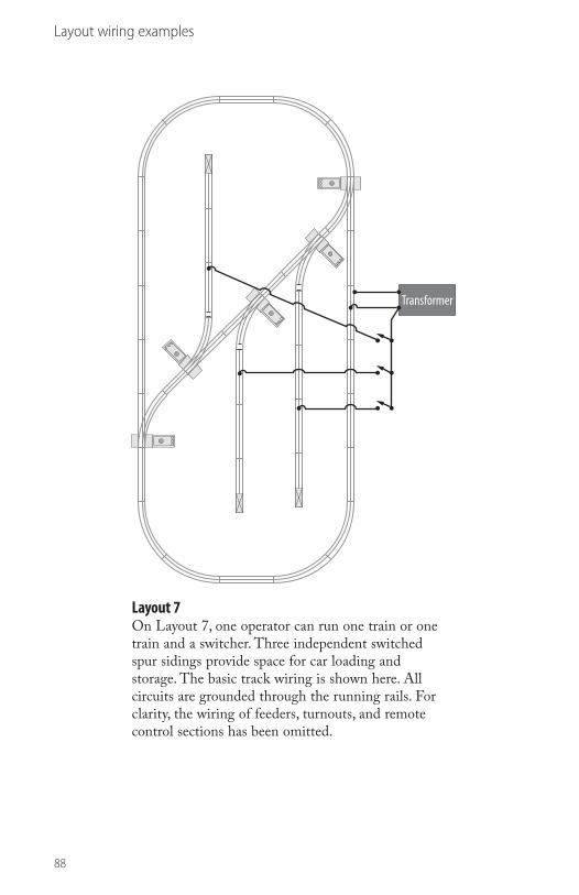
88
Layout wiring examples
Transformer
Layout 7On Layout 7, one operator can run one train or one train and a switcher. Three independent switched spur sidings provide space for car loading and storage. The basic track wiring is shown here. All circuits are grounded through the running rails. For clarity, the wiring of feeders, turnouts, and remote control sections has been omitted.
BKS-108375-BM.indd 88 7/15/08 1:18:46 PM

89
Layout wiring examples
Transformer
Transformer
Layout 8This layout shows how to wire a fixed-voltage power bus for the turnout motors. For positive action, 18 to 20 volts are recommended.
BKS-108375-BM.indd 89 7/15/08 1:18:48 PM
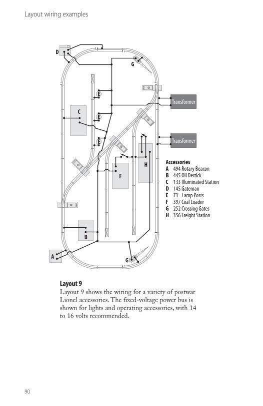
90
Layout wiring examples
AccessoriesA 494 Rotary BeaconB 445 Oil DerrickC 133 Illuminated StationD 145 GatemanE 71 Lamp PostsF 397 Coal LoaderG 252 Crossing GatesH 356 Freight Station
H
G
G
F
E
E
E
D
C
B
A
Transformer
Transformer
Layout 9Layout 9 shows the wiring for a variety of postwar Lionel accessories. The fixed-voltage power bus is shown for lights and operating accessories, with 14 to 16 volts recommended.
BKS-108375-BM.indd 90 7/15/08 1:18:50 PM

91
Layout wiring examples
Completely automatic two-trolley line with station stopsLionel’s four-wheel Birney trolley cars have long been popular with operators. Designed to automatically reverse themselves upon impact with track bumpers, these little cars provide continuous point-to-point background activity. However, watching one car trek predictably between the bumpers soon becomes monotonous. It is easy to add operational variety to your layout with these trolleys. The station stop capability means more action than just bump-and-go.
This layout provides a new setting for them. It is com-pletely automatic, requiring no attention from the operator, once it is set in motion. It features two trolley cars that make a number of stops on a small O-27 “waterwings” style layout. To make it more interesting, there’s a stretch of single track between the loops that the cars must share, while moving in both directions.
The concept is quite simple and can be set up using specially insulated track sections and a pair of O-27 non-derailing turnouts. The two trolley cars will literally control themselves, automatically stopping and starting while throw-ing turnouts for the correct route. And it is accomplished without complicated wiring or relays.
As the diagram on the next page indicates, the layout has a continuous hot center rail with two insulated running rails at the stop sections and one insulated running rail at the trip sections. When the moving trolley car goes over a trip section, contact is made through the axles, and power is transmitted by wire to the appropriate stop section, which starts the other car.
Using insulated track sections and a pair of turnouts, trolley cars can control themselves on a layout.
BKS-108375-BM.indd 91 7/15/08 1:18:56 PM

92
Layout wiring examples
The operation cycle begins with cars at points A and B on the layout. Since stop sections immediately follow trip sec-tions, there is little danger of collision. The additional current drawn when both cars are in motion adds to the realism by giving the impression of acceleration and braking.
The O-27 non-derailing turnouts are wired in tandem. As a result, they are simultaneously thrown for the correct route. When number 1 is thrown to red (the curved route), number 2 is thrown to green (the straight route), and vice versa.
More stops may be added to the line, but always in an odd number. Because the trolley cars are short, the stops do not need to be more than one track section in length. The trips should be at least two sections long. For optimum perfor-mance, you will probably have to experiment with various transformer settings.
The stop sections are easy to make. Insert four insulating pins into the running rails at both ends of the track section.
The trip sections have to be fabricated. The key is in isolat-ing one running rail, using the fiber insulators from discarded pieces of track. Since the trips have to be two track sections in length, a steel pin is inserted in the middle and insulating pins at both ends of the insulated running rail.
Fiber insulating pins To transformer
Trip
Stop
Stop
O-27 non-derailing switches
Trip
Stop
TripB
A
1 2
BKS-108375-BM.indd 92 7/15/08 1:19:01 PM

93
Alternating current (AC): Its flow of current rapidly alternates in direction many times per second. O gauge toy trains operate on this type of power.
Amperage: Unit of electrical measure that indicates the flow capacity of the system.
Block: A zone of control used when running two trains. It is an insulated stretch of track connected to its own On/Off switch or to a separate transformer throttle.
Circuit: Flow of electrical current that begins at the power source, travels to the object to be electrified, and returns to the power source.
Circuit breaker: Safety device that protects a transformer from burning out.
Coil: Wire wound around an iron core. In a transformer, the primary coil induces a weaker electrical field in the secondary coil to reduce voltage to a safe level.
Common ground: Wire that serves as a ground from track blocks, lights, or accessories on return to the power source.
Contactor: Contact-plate or spring-loaded switch that fits under track to operate train-activated accessories.
Direct current (DC): A relatively steady flow of current in only one direction, usually expressed as flowing from positive to negative in a circuit.
DPDT: A double-pole, double-throw switch can direct cur-rent from two separate circuits along two of four different paths. Some have an Off position between the poles.
DPST: A double-pole, single-throw switch is an On/Off switch that handles the power from two separate circuits.
Ground: Return leg or negative side of a circuit.
Ohm: Unit of electrical measure that indicates resistance.
Phasing: Linking two or more transformers on a layout by plug-ging all transformer cords into electrical outlets the same way, so trains pass smoothly from one insulated block to another.
Glossary
BKS-108375-BM.indd 93 7/15/08 1:19:04 PM
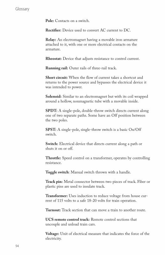
94
Pole: Contacts on a switch.
Rectifier: Device used to convert AC current to DC.
Relay: An electromagnet having a movable iron armature attached to it, with one or more electrical contacts on the armature.
Rheostat: Device that adjusts resistance to control current.
Running rail: Outer rails of three-rail track.
Short circuit: When the flow of current takes a shortcut and returns to the power source and bypasses the electrical device it was intended to power.
Solenoid: Similar to an electromagnet but with its coil wrapped around a hollow, nonmagnetic tube with a movable inside.
SPDT: A single-pole, double-throw switch directs current along one of two separate paths. Some have an Off position between the two poles.
SPST: A single-pole, single-throw switch is a basic On/Off switch.
Switch: Electrical device that directs current along a path or shuts it on or off.
Throttle: Speed control on a transformer, operates by controlling resistance.
Toggle switch: Manual switch thrown with a handle.
Track pin: Metal connector between two pieces of track. Fiber or plastic pins are used to insulate track.
Transformer: Uses induction to reduce voltage from house cur-rent of 115 volts to a safe 18-20 volts for train operation.
Turnout: Track section that can move a train to another route.
UCS remote control track: Remote control sections that uncouple and unload train cars.
Voltage: Unit of electrical measure that indicates the force of the electricity.
Glossary
BKS-108375-BM.indd 94 7/15/08 1:19:05 PM

95
Accessory operating voltage . . . . . . . . .61-62
Alternating current (AC) . . . . . . . . . . . .6, 51
Amperage . . . . . . . . . . . . . . . . . . . . . . . .7, 16
Amp meter . . . . . . . . . . . . . . . . . . . . . .78-79
Automatic train control . . . . . . . . . . . .52-54
Block . . . . . . . . . . . . . . . . . . . . 42-44, 46, 50
Block control . . . . . . . . . . . . . . . . . . . .41-44
Block signal . . . . . . . . . . . . . . . . . . . . .57, 74
Bus wire . . . . . . . . . . . . . . . . . . . . . 32, 34-35
Cab control . . . . . . . . . . . . . . . . . . . 41, 43-45
Circuit . . . . . . . . . . . . . . . . . . . . . . .8, 31, 83
Circuit breaker . . . . . . . . . . . . . . . . . . .10, 18
Common ground . . . . . . . . . . . . . . . . .31-33
Contactor . . . . . . . . . . . . . . . . . . . . . . .55-61
Crossover . . . . . . . . . . . . . . . . . . . . . . .63, 71
Direct current (DC) . . . . . . . . . . . . . . . .6, 51
DPDT . . . . . . . . . . . . . . . . . . . . . . . . .24-25
DPST . . . . . . . . . . . . . . . . . . . . . . . . . .24-25
Electromagnet . . . . . . . . . . . . . . . . . . .21-22
Fixed voltage . . . . . . . . . . . . . . . . . .13, 15, 71
Ganging controllers . . . . . . . . . . . . . . .63-64
Gauge . . . . . . . . . . . . . . . . . . . . . . . . 7, 29-30
Insulated running rail . . . . . . . . . . . . . .59-61
Multimeter . . . . . . . . . . . . . . . . . . . 75-77, 83
Phasing transformers . . . . . . . . . . . 19-20, 75
Primary coil . . . . . . . . . . . . . . . . . . . . .12-13
Push-button switch . . . . . . . . . . . . 26, 65-67
Rectifier . . . . . . . . . . . . . . . . . . . . . . . . . . 51
Relay . . . . . . . . . . . . . . . . . . . . . . . . . . . . . 51
Rotary switch . . . . . . . . . . . . . . . . . 26, 44-45
Secondary coil . . . . . . . . . . . . . . . . . . .12-13
Sequence-reverse function . . . . . . . . . .46-47
Short circuit . . . . . . . . . . . . . . . . . . .8, 10, 77
Slide switch . . . . . . . . . . . . . . . . . . . . . . . 26
Soldering . . . . . . . . . . . . . . . . . . . . . . .38-40
Solenoid . . . . . . . . . . . . . . . . . . . . . . . .21-22
SPDT . . . . . . . . . . . . . . . . . . . . 24-25, 27, 69
SPST . . . . . . . . . . . . . . . . . . . . 24-25, 65-67
Toggle switch . . . . . . . . . . . . . . 26, 46-47, 69
Transformer . . . . . . . . . . . . . . . . . 6-7, 12-18
Troubleshooting . . . . . . . . . . . . . . . . . .42, 83
UCS remote control track . .11, 63-64, 70-71
Variable track voltage . . . . . . . . . . . . . .14-15
Voltage . . . . . . . . . . . . . . . . . . . . . . . . . .7, 12
Volt meter . . . . . . . . . . . . . . . . . . . . . . .78-79
Warning lights . . . . . . . . . . . . . . . . . . .72-73
Wattage rating . . . . . . . . . . . . . . . . .7, 13, 47
Index
BKS-108375-BM.indd 95 7/15/08 1:19:08 PM

InclinedTrack on
LocShe
CREATIVETOY TRAIN
TRACK PLANSNew themes to
inspire your next
O gauge layout
N E I L B E S O U G L O F F
16 Detailed,full-color plans
Layout Plans
• Framework construction tips
• O and S gauge trackwork roundup
• Tracklaying tips
f o r T o y T r a i n s
LayoutPlansforToyTrains
R.D. Teal
Modern Toy TrainRepair and
Maintenance
Trackwo
rk for To
y Trains
Peter H
. Rid
dle
Peter H. Riddle
• Choosing the right track• Wiring your track• Customizing rail sections
• Choosing the right trackToy TrainsToy Toy for
Essential guide to O gauge track
Toy TrainsTrainsTTRACKWORK
PMK-BKS-108375RH
Available at your favorite hobby shop!or at CTTBooks.com, and 1-800-533-6644 Shipping and handling charges apply. Call for details or view online.
ExpertTips ...to get your model railroads up and running!
You’ll find 16 realistic, themed layout plans, each including track diagrams, wiring schemes, and a list of suggested equipment in this book.10-8350 • $18.95
Features layout descriptions, track requirements, operating suggestions, and track plans for layouts that will fit bedroom to basement-sized space.10-8275 • $15.95
Includes techniques and steps for lubrication, troubleshooting, and the right way to replace tires, batteries, and light bulbs.10-8327 • $17.95
Provides an overview of the various lines of sectional and flexible track, and demonstrates how to cut, bend, wire,and install track into your layouts.10-8365 • $19.95
XTT
PMK-BKS-108375.indd 1 7/28/08 11:18:00 AM

— Traditional layout wiring —
WIRINGHandbook for Toy Trains
Ray L. Plummer9 7 8 0 8 9 7 7 8 5 3 3 4
ISBN 978-0-89778-533-4
5 1 7 9 5
$17.95 U.S. 108375
Wire your layout the traditional wayThis handbook is the one guide to have handy when wiring a toy train layout. Classic Toy Trains columnist Ray L. Plummer provides easy-to-follow explana-tions, which are accompanied by numerous illustrations, photos, and sample wiring layouts.
The handbook describes how to
• Master the basics of electricity and wiring
• Hook up transformers, switches, and other components
• Select, connect, and solder wire
• Operate two trains using block or cab control
• Wire accessories and replace controllers
• Maintain and troubleshoot a layout
0 6 4 4 6 5 1 8 3 7 5 3
Wiring H
andbook for Toy TrainsPlum
mer
Hobby
www.KalmbachBooks.com
BKS-108375-CV.indd 1 7/28/08 1:25:03 PM