Embed Size (px)
Citation preview
MAN 650066:J 1
VACUUM FLUORESCENT DIGITAL DASHBOARD
SERIES 3
NOW WITH SOLID STATE SENSOR TECHNOLOGY
INSTALLATION AND OPERATION MANUAL
Please read this before beginning installation or wiring.
IMPORTANT NOTE! This system has an odometer preset option that is only available for the first 100 miles (160km) of operation. See odometer preset section for instructions and setup information.
MAN 650066:J 2
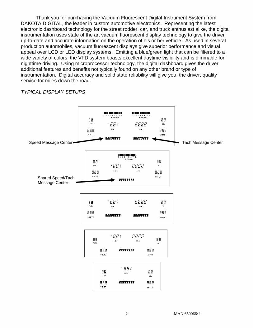
Thank you for purchasing the Vacuum Fluorescent Digital Instrument System from DAKOTA DIGITAL, the leader in custom automotive electronics. Representing the latest electronic dashboard technology for the street rodder, car, and truck enthusiast alike, the digital instrumentation uses state of the art vacuum fluorescent display technology to give the driver up-to-date and accurate information on the operation of his or her vehicle. As used in several production automobiles, vacuum fluorescent displays give superior performance and visual appeal over LCD or LED display systems. Emitting a blue/green light that can be filtered to a wide variety of colors, the VFD system boasts excellent daytime visibility and is dimmable for nighttime driving. Using microprocessor technology, the digital dashboard gives the driver additional features and benefits not typically found on any other brand or type of instrumentation. Digital accuracy and solid state reliability will give you, the driver, quality service for miles down the road. TYPICAL DISPLAY SETUPS
Speed Message Center Tach Message Center
Shared Speed/Tach Message Center
MAN 650066:J 3
WARNING
The vacuum fluorescent displays are made of glass and should be handled with care.
MOUNTING UNIVERSAL DISPLAY SYSTEMS WITH SUBPANELS
When mounting instrumentation systems mounted to an ABS subpanel, begin by removing the subpanel from the aluminum. Cut an opening in the dash just smaller than the outer dimensions of the aluminum panel. Remove all nuts and washers from the studs on the back side of the panel and insert into the hole. Next, install four washers or clips and secure with a nut on each. This is what holds the panel to the dashboard. Now, install a nut on each stud and set the display panel in place over the studs. If the studs were bent slightly inward from securing the aluminum panel, you may have to bend them outward to line up with the holes on the ABS subpanel. Always lay the display panel aside when not in use to avoid accidentally damaging the displays. Once aligned, secure it with an additional four nuts. Leave a gap of no less than 1/8" between the display glass and the front lens material. Be careful not to compress the glass against the front lens. Again, note that the displays are glass and should be handled with care.
MOUNTING SYSTEMS WITH DISPLAYS MOUNTED TO ALUMINUM
When mounting year specific aluminum panel, cut an opening into the dashboard if necessary and secure the entire panel with the instrumentation using the appropriate mounting hardware. Some panels are set into the front of the dash while others are installed from the rear of the dash. The exact mounting configuration will depend on what year car and panel you are installing.
MOUNTING SINGLE LENS SYSTEMS
Your DAKOTA DIGITAL single lens system will come to you with a single plexiglass lens and instrumentation that is mounted in an aluminum case. The lens and the instrumentation have corresponding mounting holes. After you have affixed the mounting studs of your choice to the backside of your dash, the lens piece should be slid over the studs followed by the display system. The lens can be secured with either washers and nuts, or by a bead of RTV around the back side of the lens and case. If RTV is used, the system will need to be held in place until it has had time to cure. The lens should be tight against the aluminum display case.
Adjust the height of the panel so that the glass displays are 1/8" away from the front lens. Applying a lock washer and nut to the studs behind the display panel, secure the display panel to the bezel. If screws were provided with the panel, secure them through the display panel and into the bezel. No additional holes should need to be drilled. All holes in the display systems are pre-drilled at the factory.
MAN 650066:J 4
MOUNTING KITS INTO ORIGINAL DASHES
Some kits will include a separate mounting instruction sheet so please see that first for system mounting instructions. Some systems will attach directly to the bezel, and others will mount back into the instrument cans where the factory gauges were mounted. There are three basic system mounting configurations; read on to identify your system and how to mount it. It may be necessary to trim or remove some plastic or bezel material depending on the system. You may also need the following tools and materials to complete a system install depending on the vehicle:
Screw drivers
Nut drivers
Side cutters
Die grinder
Cut off wheel
Silicone / RTV
Complete Systems mounted in new bezel If your system came from Dakota Digital with a new bezel, installation on the system
should be straight forward. Remove the factory gauges and bezel and install the new one.
Systems that have a glue-in lens (loose lens with no mounting holes in it) If your system included a front lens separate from the displays and contains no mounting
holes, you have a glue-in lens system. The lens will be secured to the original bezel using RTV. When installing the display system into the original bezel, several steps must be taken to
prepare the bezel. The first is to remove the cluster from the dashboard. Next, remove all instrumentation from the bezel as well as the factory lens. You will generally be left with a bare plastic or metal bezel. Remove any felt inserts from the back side of the bezel that sit between the lens and the bezel. Next, take the supplied lens, remove any masking that may be on it and with the lettering facing the front of the dash, place it in the bezel. Lay a bead of RTV around the edge of the lens to secure it in place. After the RTV has cured, the display panel is ready to be placed on the bezel. If studs were supplied with the panel, screw them into the bezel and place a nut on them before placing the display system on it.
Systems that mount into original cans with hardware (lens and systems screw together) If the system came with the lens and system attached together, the complete assembly should either mount into the original cans or secure directly to the bezel. Some systems may come with a new can or housing over the back of the system that should make mounting very apparent. If you have a version with a system and lens attached to ABS plastic, you will need to secure these to the original cans or instrument housings.
First, remove the cluster from the dashboard. Next, remove all instrumentation from the bezel as well as the factory lens. You should essentially be left with a bare bezel, possibly reusing any clear lenses that were covering the factory gauges. If you have a system that came in a new can or has an ABS subpanel that fits over the factory bezel, you can secure it back to the bezel and re-install into the car.
If your system mounts into the cans, continue removing the stock gauges as well as other lights and loose parts from the instrument cans as the display systems typically sit flat into the can so everything must be removed. Once the cans are cleared, the system should fit into the can and secure from the back of the can with screws. The ABS sub-panel should have some mounting holes and supplied hardware for securing the system to the can. Once system is secure, reattach cans to the bezel and re-install into the car.
MAN 650066:J 5
GAUGE SYSTEM FEATURES Mileage readings
Million mile odometer
Two (A/B) re-settable trip odometers (0-9999.9)
Re-settable service countdown odometer (0-9999) Performance readings
High speed recall. This is automatically reset at power up or can be manually reset.
High RPM recall. This is automatically reset at power up or can be manually reset.
0-60 mph (0-100kmh) time
¼ mile time
¼ mile trap speed. This is reset when the ¼ mile time restarts. Hour meter
Resettable hours (0-999.9) English/metric conversion
Alternate speed can be displayed on message display. Special tachometer displays
On systems that do not have bar graph displays, a bar tach can be shown on the message display.
On systems that do not have a digital tachometer display, the rpm can be shown on the message display or the tachometer reading can be switched onto the speed display.
Built-in Indicators
Left/Right Turn signal indicators
High Beam indicator
Check Engine indicator
Brake Warning indicator
4x4 indicator
Wait to Start indicator
Cruise Control indicator
Gear Position indicator which displays full gear word with use of Dakota Digital GSS-2000 (purchased separately)
Special outputs
Shift output to activate external light
Selectable 2000ppm or 4000ppm speed output for cruise or ECM (not available when using BIM-01-X for speed)
Demonstration mode
Holding Switch 2 while turning on the key will start the system going through a preset sequence of readings. To exit the demo mode, turn the key off. You may also wire up a separate switch to power the gauges for demo mode without powering the entire vehicle.
Auxiliary gauge readings in tach message display with expansion bus interface modules (BIM) (purchased separately)
MAN 650066:J 6
MESSAGE DISPLAYS
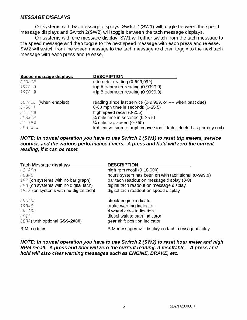
On systems with two message displays, Switch 1(SW1) will toggle between the speed message displays and Switch 2(SW2) will toggle between the tach message displays.
On systems with one message display, SW1 will either switch from the tach message to the speed message and then toggle to the next speed message with each press and release. SW2 will switch from the speed message to the tach message and then toggle to the next tach message with each press and release. Speed message displays DESCRIPTION . ODOMTR odometer reading (0-999,999) TRIP A trip A odometer reading (0-9999.9) TRIP B trip B odometer reading (0-9999.9) SERVIC (when enabled) reading since last service (0-9,999, or ---- when past due) 0-60 T 0-60 mph time in seconds (0-25.5) HI SPD high speed recall (0-255) QUARTR ¼ mile time in seconds (0-25.5) QT SPD ¼ mile trap speed (0-255) KPH xxx kph conversion (or mph conversion if kph selected as primary unit)
NOTE: In normal operation you have to use Switch 1 (SW1) to reset trip meters, service counter, and the various performance timers. A press and hold will zero the current reading, if it can be reset.
Tach Message displays DESCRIPTION . HI RPM high rpm recall (0-18,000) HOURS hours system has been on with tach signal (0-999.9) BAR (on systems with no bar graph) bar tach readout on message display (0-8) RPM (on systems with no digital tach) digital tach readout on message display TACH (on systems with no digital tach) digital tach readout on speed display ENGINE check engine indicator BRAKE brake warning indicator 4W DRV 4 wheel drive indication WAIT diesel wait to start indicator GEAR( with optional GSS-2000) gear shift position indicator
BIM modules BIM messages will display on tach message display
NOTE: In normal operation you have to use Switch 2 (SW2) to reset hour meter and high RPM recall. A press and hold will zero the current reading, if resettable. A press and hold will also clear warning messages such as ENGINE, BRAKE, etc.

MAN 650066:J 7
CONTROL BOX MOUNTING
Once the display panel is in place, mount the control box within reach of the ribbon cable on the display panel (approximately 3 feet). Choose a mounting location that will allow you access to wire all of the inputs on the control box. Double sided tape, hook and loop fasteners, or screws in the two tabs on the case work fine for securing the control box under the dash.
When selecting a mounting location, avoid placing the control module next to, or just opposite of the firewall from, ignition components, ie: Ignition coil, HEI, etc. Ignition components can emit tremendous amounts of electric noise, affecting the operation of electrical components.
Wiring the control box into the vehicle
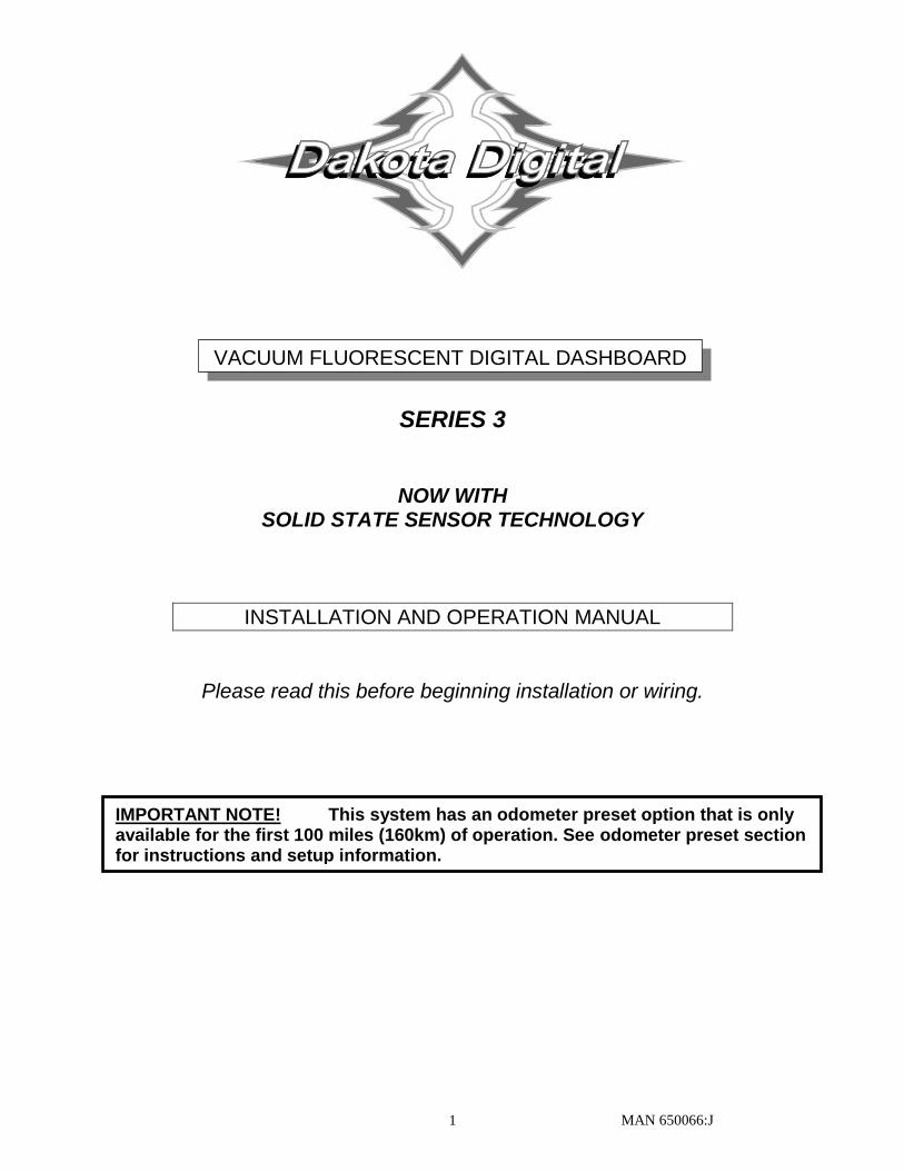
While the control box contains several connections, the wiring is straightforward. Depending on how many auxiliary functions you want displayed, not every terminal will be used in most applications. Below we describe the function of each terminal, what they do, and how to wire them.
TACH
POWER
GROUND
WARN
DIM (+)
SPD +
SPD SND
SPD -
SPD OUT
SW2 (-)
SW1 (-)
ADJ SND
ADJ -
WTR SND
WTR -
OIL +
OIL SND
OIL -
RESERVED
(SEE MANUAL)
FUEL SND
FUEL -
WAIT (+)
CRUISE (-)
GEAR (1 WIRE)
4x4 (-)
RIGHT (+)
LEFT (+)
HIGH (+)
BRAKE (-)
CHECK ENG (-)
SE
RIE
S III
VF
D C
ON
TR
OL
BO
X
RIB
BO
N C
AB
LE
AU
X.
I/O
DIS
PL
AY
ST
RIP
E
ww
w.d
akota
dig
ital.c
om
techsu
ppo
rt@da
kota
dig
ital.c
om
60
5-3
32
-651
3
CHECK ENGINE INDICATOR INPUT
BRAKE SYSTEM/PARKING BRAKE WARNING INPUT
HIGH BEAM INDICATOR INPUT
LEFT TURN SIGNAL INDICATOR INPUT
RIGHT TURN SIGNAL INDICATOR INPUT
4 WHEEL DRIVE INDICATOR INPUT
1-WIRE GEAR INDICATOR INPUT (FROM GSS UNIT)
WAIT TO START INDICATOR INPUT
CRUISE ENGAGED INDICATOR INPUT
FUEL LEVEL SENSOR GROUND OUTPUT
FUEL LEVEL SENSOR INPUT
NOT TYPICALLY USED
OIL PRESSURE SENSOR GROUND OUTPUT
OIL PRESSURE SENSOR INPUT
OIL PRESSURE SENSOR POWER OUTPUT
WATER TEMPERATURE SENSOR GROUND OUTPUT
WATER TEMPERATURE SENSOR INPUT
NIGHT DIMMING ADJUSTMENT GROUND OUTPUT
NIGHT DIMMING ADJUSTMENT INPUT
SPEED SELECT SWITCH INPUT SW1
TACH SELECT SWITCH INPUT SW2
2000 PPM SPEED SIGNAL OUTPUT
VEHICLE SPEED SENSOR GROUND OUTPUT
VEHICLE SPEED SENSOR SIGNAL INPUT
VEHICLE SPEED SENSOR POWER OUTPUT
NIGHT DIMMING INPUT
RPM WARNING/SHIFT OUTPUT
TACHOMETER INPUT
+12 VOLT ACCESSORY POWER INPUT
MAIN CHASSIS GROUND INPUT
STATUS LED
TO DISPLAY SYSTEM
CONNECTOR
BIM CONNECTION
MAN 650066:J 8
TA
CH
PO
WE
R
GR
OU
ND
WA
RN
DIM
(+
)
SP
D +
SP
D S
ND
SP
D -
SP
D O
UT
SW
2 (
-)
SW
1 (
-)
AD
J S
ND
AD
J -
WT
R S
ND
WT
R -
OIL
+
OIL
SN
D
OIL
-
R
ES
ER
VE
D
(S
EE
MA
NU
AL
)
FU
EL
SN
D
FU
EL
-
W
AIT
(+
)
C
RU
ISE
(-)
G
EA
R (
1 W
IRE
)
4
x4
(-)
R
IGH
T (
+)
L
EF
T (
+)
H
IGH
(+
)
B
RA
KE
(-)
C
HE
CK
EN
G (
-)
SERIES IIIVFD CONTROL BOX
RIBBON CABLE AUX.
I/O
DISPLAY
STRIPE
www.dakotadigital.com
605-332-6513
MOM
ENTA
RY S
W2
MOM
ENTA
RY S
W1
RIBBON CABLE
DISPLAY PANEL
STATUS LED
DIM-1
Optional
Cruise Control
Engage Output
Glow Plug Relay
or
Wait To Start
Output
ECU/ECM
Check Engine
Output
BIM
CONNECTION
ONLY!
4x4
Transfer Case
Switch
DAKOTA DIGITAL
GSS UNIT
1-Wire output
Right Turn
Signal Wire
Optional
Left Turn
Signal Wire
High Beam
Wire
Parking Brake
Switch
SPEED OUT
(2k or 4k PPM)
Connect to tail light circuit
dash will dim when terminal has +12V
Light or Buzzer
(4 Watts or more)
Tail Light
Light or Buzzer
(4 Watts or less)
Relay
EXISTING
FUEL LEVEL
SENSOR
RE
D
WH
ITE
BL
AC
K
Additional ground wire to fuel
sensor body or mounting screw.
PRESSURE SENSOR
SEN-03-8
0-100 PSI
TEMP SENSOR
SEN-04-5
100-300 F
PULS
E G
ENERATO
R
ECU/ECM
Speed Output
RE
D
WH
ITE
BL
AC
K
+12V KEY ON POWER
(fused 5 - 20 AMP max)
Connect to main
chassis ground
Ignition Coil
(negative side)
- +ECU/ECM
or Ignition Box
(tach output)
SPEED SENSOR
SEN-01-5
16k PPM
BL
UE
or R
ED
BR
OW
N o
r BL
AC
K
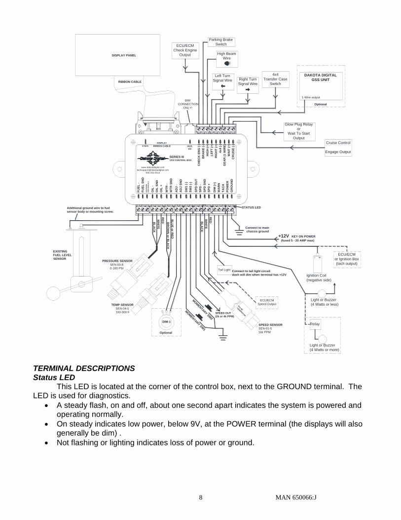
TERMINAL DESCRIPTIONS Status LED This LED is located at the corner of the control box, next to the GROUND terminal. The LED is used for diagnostics.
A steady flash, on and off, about one second apart indicates the system is powered and operating normally.
On steady indicates low power, below 9V, at the POWER terminal (the displays will also generally be dim) .
Not flashing or lighting indicates loss of power or ground.
MAN 650066:J 9
GROUND This is the main ground for the display system. A wire should be run from this terminal to
the vehicle’s main chassis ground. Use 18 AWG or larger wire to ensure sufficient grounding. Proper vehicle grounding is extremely important for any gauges (or electronics) to
operate correctly. The engine block should have heavy ground cables to the battery, frame, and firewall. Failure to properly ground the engine block or the control box can cause incorrect or erratic operation. POWER
Connect the POWER terminal to accessory +12V power from the fuse panel or vehicle wiring harness. This terminal should have power when the key is on or in accessory position. In addition to powering the display system, this is also where the voltmeter gauge senses the vehicle electrical system voltage. The supply source should be a fused 5 - 20 amp circuit, the system only draws about 1 amp, so sharing an existing accessory circuit will generally be fine. Use 18 AWG wire to ensure the system receives a sufficient power feed. *** Never connect this to a battery charger alone. It needs to have a 12 volt battery connected to it. Battery chargers have an unregulated voltage output that will cause the system to not operate properly and may cause damage to the control box.
TACH
Depending on the type of instrument system that you have, there may be a bar graph tachometer, a digital tachometer, or both. Connect the TACH terminal to the ignition system. On vehicles using a separate ignition coil, connect to the negative side of the coil. The negative side of the coil will be the wire that goes to the points or electronic ignition module. For GM HEI ignition, connect to the terminal marked “TACH” or on some systems, a single white wire with a spade terminal on it. On some aftermarket ignition systems, connect to the TACH output terminal. On computer controlled ignition systems, consult a service manual for the wire color and location. With a magneto system, connect to the kill wire for the tach signal. Do not connect the TACH terminal to the secondary, or high voltage side of the ignition coil.
To avoid having to locate a compatible connection, a Dakota Digital BIM-01-X may also be used with most 1996 or newer OBDII compliant computer systems to provide a tachometer reading. When using the BIM-01-X, select “BUS” for the engine cylinder setting.
To ensure that the ignition system does not interfere with any other dashboard functions, do not run the tachometer wire alongside any other sender or input wires. DO NOT USE SOLID CORE SPARK PLUG WIRES WITH THIS DASHBOARD SYSTEM. Solid core ignition wires cause a large amount of electromagnetic and radio frequency interference which can disrupt the system operation.
The tachometer is compatible with almost all gasoline engines. The engine cylinder selection, display update rate, tach signal type, and rpm warning point can be adjusted in the setup menu under “TACH”. If a diesel engine is being used, you will need a tach interface, such as Dakota Digital’s DSL-1 or DSL-2. Be aware of the cylinder setting when using computer outputs or reading the tach signal from an ECU. GM LS engines require the tach to be set up for a 4 cylinder, low voltage signal when reading from the ECU even though it is a V8 engine. WARN
The WARN terminal is an output for a relay or small light. The output is ground-activated when the preset rpm limit is exceeded. This output can turn on a 4 Watt or smaller 12 volt bulb or can activate a relay to turn on a larger bulb. To wire a warning light to this output, connect one wire from the bulb to 12 volt accessory power and connect the other wire to the WARN terminal.
MAN 650066:J 10
DIM The gauges are designed to dim when the headlights are turned on. This is to reduce the
display intensity at night so the gauges do not cause eye strain or reduced night vision. Connect this terminal to the tail light or parking light circuit so that it has 12 volts whenever the headlights are on. When this terminal does not have power, the display system will be at full brightness. When power is applied, the display dims to an adjustable level.
The night brightness level is adjustable two different ways. This preset brightness is adjusted in the setup menu “NIGHT”. See ADJ SND for a description of the second method. By default the system will dim to about ½ brightness when DIM terminal gets +12V. SPD +
This terminal is used to supply power to Dakota Digital speed sensor SEN-01-5. This supplies 5V DC to the sensor and should not be connected up to anything else. Connect the RED wire from the SEN-01-5 to this terminal.
If you are using a 1-wire VSS output from a computer or a 2-wire pulse generator, this terminal should be left open. ***DO NOT use this terminal to power any other devices; it is a low current +5V output.
SPD SND
This is where the vehicle speed sensor (VSS) connects. The signal supplied to this terminal will be used by the control box to calculate the speed reading on the display and also for calculating and saving odometer mileage.
Dakota Digital supplies a 3-wire sensor for most of its kits; SEN-01-5. If you are using this sensor, the WHITE wire is the speed signal; connect to SPD SND. The RED and BLACK wires in the cable are power and ground (5V DC) and their connection is discussed in SPD + and SPD -.
For 2-wire speed sensors such as a cable driven pulse generator, the polarity of the wires does not matter. Connect one wire to the SPD – (Ground) and the other to the SPD SND terminal. The speed sensor ground wire should be brought back to the control box to ensure a proper signal is received. Twisting the ground and signal wires around each other provides an additional level of interference protection. The speed signal wire should not be routed alongside tach, ignition, or other high current or high voltage wires.
For vehicles which have a vehicle speed signal from a transmission sensor or ECM, tap into the VSS wire and connect it to the SPD SND. Consult a vehicle service manual or wiring diagram to determine wire color and location.
To avoid having to locate a compatible connection, a Dakota Digital BIM-01-X may also be used with most 1996 or newer OBDII compliant computer systems to provide a speedometer reading. When using the BIM-01-X, select “BUS” for the sender setting.
This system can accept 4000 ppm – 128,000 ppm speed signals with room for adjustment. The speedometer is fully adjustable and calibration is discussed in a later section.
***Failure to calibrate the speedometer may cause your odometer mileage to increase very rapidly if the speedometer is reading too fast.
*** The speed signal wire should NOT be routed alongside ignition components, tach signal, or other high current/voltage wires. SPD – This terminal is used for speed sensor ground. The wire color is BLACK on a 3-wire sensor. This insures a proper ground as well as providing proper hook-up for a twisted pair of wires, or a solid state sensor. Only ground the speed sensor here. If you are using a single wire output from a computer for the VSS then this terminal should be left open.
MAN 650066:J 11
SPD OUT This terminal can be used to supply a speed signal to auxiliary devices such as a cruise control or radio volume adjustment. The output is scaled to the input speed signal coming into the SPD SND terminal. It can be set to 2000 PPM or 4000 PPM.
***If you are using the BIM-01-X bus speed signal option this output will NOT work.
SW2 (-) or Tach Switch The SW2 terminal is used for selecting the various rpm, engine, and warning displays
and also for entering the demonstration mode. The SW2 input is activated by a ground connection. The push button switch supplied (or any momentary, normally open switch) is wired by connecting one wire to SW2 and the other wire to a ground. When the button is pressed and released, the tach message display will change. When the button is pressed and held for a few seconds, any re-settable information displayed will be zeroed. On systems with two message displays, the one below the tach is dedicated to rpm/warn messages. On systems with one message display the speed/performance and rpm/warn messages will use the same display.
To enter DEMO mode, press and hold SW2 while turning the key on. The system will light up and say DAKOTA DIGITAL on the message readouts, release the switch and the system will stay in demo mode until the power is cycled off and back on without the switch held. SW1 (-) or Speed Switch
The SW1 terminal is used for selecting the various speed, distance, and performance displays and also for entering the setup menu. The SW1 input is activated by a ground connection. The push button switch supplied (or any momentary normally open switch) is wired by connecting one wire to SW1 and the other wire to a ground. When the button is pressed and released, the speed message display will change. When the button is pressed and held for a few seconds, any re-settable information displayed will be zeroed. On systems with two message displays, the one below the speed is dedicated to speed/performance messages. On systems with one message display the speed/performance and rpm/warn messages will use the same display.
ADJ SND
The ADJ SND terminal is an optionally used input that allows you to have control over the dimming brightness. By default, the system will dim to approximately half brightness when the DIM terminal has power, +12V, but this level is adjustable in the NIGHT setup menu. Using the ADJ SND terminal allows you to have a dash mounted control to vary the brightness while the headlights are on. This requires Dakota Digital’s DIM-1 kit; a stock headlight rheostat will not work.
The DIM-1 has a WHITE/BLUE wire and a BLACK wire. Connect the WHITE/BLUE to the ADJ SND terminal and the BLACK to ADJ - ground. The dash mounted dimmer will only vary the display brightness when the DIM terminal has power, +12V. ADJ – This terminal provides a ground reference for the optionally installed DIM-1 for dash mounted dimming control. The BLACK wire will connect to the ADJ – terminal, the WHITE/BLUE connects to the ADJ SND. *This terminal should not be used for grounding any other sensors or devices as damage to the control box will occur. If not using a Dakota Digital DIM-1, this terminal should be left open.
MAN 650066:J 12
WTR SND The water temperature sender included with this system must be used. Other
senders will cause incorrect readings or damage to the control box. The supplied sensor, Dakota Digital SEN-04-5, is a 100-300ºF(40-150ºC) temp sensor.
The sender mounts on the engine block or into the intake manifold so that the end of the sensor is in the engine coolant flow. It has 1/8” NPT threads and the included adaptor bushings may be used to adapt it for various applications.
To avoid mounting an additional temperature sender on the engine, a Dakota Digital BIM-01-X may also be used with most 1996 or newer OBDII compliant computer systems to provide an engine temperature reading. When using the BIM-01-X, select “BUS F” or “BUS C” for the sender type.
The water temp sensor has two wires coming from the harness. The BLUE or RED wire will connect to the WTR SND terminal, the BROWN or BLACK wire will connect to the WTR –.
Due to the construction of the sensor, readings at temperatures below 100 ºF may be inaccurate. The sensor is designed to be accurate from approximately 100 ºF - 300 ºF.
WTR –
This is the ground reference used for 2-wire water temp sensors. This will connect to the BROWN or BLACK wire from the Dakota Digital SEN-04-5. The BLUE or RED wire will connect to the WTR SND terminal. ***DO NOT connect this terminal to any other devices
OIL +
This terminal is used to supply power to Dakota Digital pressure sensor SEN-03-8. This supplies 5V DC to the sensor and should not be connected to anything else. Connect the RED wire from the SEN-03-8 to this terminal. ***DO NOT use this terminal to power any other devices; it is a low current +5V output. OIL SND
The oil pressure sender included with this system must be used. Other senders will cause incorrect readings or damage to the control box.
The supplied sensor, Dakota Digital SEN-03-8, is a 0-100 psi solid state pressure sensor. The sender can mount on the engine block or in an oil pressure line off of the block. The sender has 1/8” NPT threads. The included adaptor bushings may be used to adapt it for various applications.
The oil pressure sensor has three wires coming from the harness, plus one bare shield wire. The WHITE wire will connect to the OIL SND terminal, the RED to OIL + (5V DC), and the BLACK and bare shield wire to OIL –. Do not route the oil sender wire alongside a spark plug wire or other high current or high voltage wires. Doing so can cause incorrect or erratic gauge readings.
If the oil pressure drops below an adjustable warning point, the reading will flash as a low oil pressure warning. The default warning point is 10 psi. If the oil display shows “---” this indicates that the control box is sensing an open circuit, a short to ground, or out-of-range error from the sender or sender wire. If the oil display shows “EEE” this indicates that the control box is sensing a short to power or an out-of-range error from the sender. If either indication remains on the display, inspect the sender wire for damage, check the routing of the sender wire, check the sending unit grounding, and check that the correct sending unit is connected.
MAN 650066:J 13
OIL – This is the ground reference used for three-wire pressure sensor. This will connect to the
BLACK wire as well as the bare silver shield wire from the Dakota Digital SEN-03-8. ***The bare wire is the shield wire, connect this wire to the OIL– along with the BLACK wire ***DO NOT connect this terminal to any other devices RESERVED (FUEL +)
This output is not typically used. It is a low current +12V supply for powering solid state fuel sensors. Currently, it does not have an application for any Dakota Digital fuel level sensors.
***This terminal should not be used with a typical resistive type fuel sensor. For most applications, leave this terminal open. Do not try to power other devices from this terminal or damage to the control box will occur. FUEL SND
The fuel gauge sending unit is not normally supplied because the display system can use the existing fuel sending unit in the tank in many cases. The sending units that are compatible with this system are as follows: GM, Ford, VDO, and Stewart Warner. It is also possible to program a custom setting for senders that are not pre-programmed into the system.
Use the FUEL - and FUEL SND terminals and run a twisted pair of wires back to your fuel level sensor. Connect the FUEL - terminal to the fuel level sensor body or a mounting screw to insure the sensor is sufficiently grounded. The other wire is the sensor signal which goes to the FUEL SND terminal.
If your wiring harness already has a single wire routed through the vehicle for the fuel sender then it may be used. If using a wire from an existing harness, make sure that the wire does not have power. The fuel sender gets power from the control box only. Fuel senders reference their ground from the sender mounting plate.
The fuel sender type is selected using the setup menu under “FUEL”. The settings are discussed later in the setup section. Anytime the fuel level is below 10%, the reading will flash as a warning of low fuel.
The fuel gauge will initially display “FL” until the fuel sender type has been set. If the fuel
display shows “ ” this indicates that the control box is sensing a short to ground or out-of-range error from the sender or sender wire. If the fuel display shows “EE” this indicates that the control box is sensing an open circuit or out-of-range error from the sender. If either indication remains on the display, inspect the sender wire for damage, check the routing of the sender wire, check the sending unit grounding, and check that the sender selection is set correctly for the sending unit that is connected.
FUEL – Connect the FUEL - terminal to the fuel level sensor body or a mounting screw to insure the sensor is sufficiently grounded. One terminal on the sensor is the signal which goes to the FUEL SND terminal.
***For fuel level sensors that are attached to an electric fuel pump, or if you have an electric fuel pump in the tank, make sure that the fuel pump is externally grounded to the vehicle chassis. Attempting to ground the fuel pump to the Dakota Digital control box will result in erratic operation and damage to the control box. CRUISE (-)
The CRUISE terminal can be used as a “cruise engaged” indicator. The CRUISE input is activated by a ground signal from a compatible cruise control harness. Whenever the CRUISE input is grounded, the system will display a small “c” to the right of the speedometer.
MAN 650066:J 14
WAIT (+) The WAIT terminal can be used as a “wait to start” or glow plug indicator. The WAIT
input is activated by a 12 volt signal from the glow plugs. Whenever the WAIT input is powered with +12V, the system will display “WAIT” on the tach message display. This message can be cleared by pressing and holding SW2, or once the WAIT terminal loses the +12V signal. GEAR (1 wire)
The GEAR terminal is used for the gear shift indicator. The indicator is built into every system, but will not light up unless a Dakota Digital GSS-1000/2000/5000 gear shift sending unit is connected or a Dakota Digital BIM-01-X with a compatible electronic transmission is used, telling the system what gear the transmission is in. The gear shift sending unit is not included with the system and must be purchased separately if desired.
The GEAR terminal will connect to the FIRST terminal on a GSS-1000 or to the 1-WIRE terminal on a GSS-2000 or GSS-5000. Follow the instructions in the GSS manual for use with a single wire display system. When the gear shift sending unit is connected, the gear name will be shown on the tach message display.
NOTE: The system will automatically change to the gear display for a few seconds whenever the gear position changes, even if viewing a different message display. 4x4 (-)
The 4x4 terminal can be used on four wheel drive vehicles. The 4x4 input is activated by a ground signal from a switch on the transfer case. Connect a wire from this terminal to the switch on the transfer case. Whenever the 4x4 input is grounded the system will display “4W DRV” on the message display. When signal turns off, the system will briefly display “2W DRV” on the message display. RIGHT (+)
The RIGHT terminal is activated by a 12 volt signal from the turn signal flasher. When this terminal has 12 volts, an arrow will light up to the right of the speedometer display. An existing wire from the vehicle for the right turn indicator can be used or a new wire can be connected from the turn signal flasher or power wire feeding the right turn signal bulb. LEFT (+)
The LEFT terminal is activated by a 12 volt signal from the turn signal flasher. When this terminal has 12 volts, an arrow will light up to the left of the speedometer display. An existing wire from the vehicle for the left turn indicator can be used or a new wire can be connected from the turn signal flasher or power wire feeding the left turn signal bulb.
HIGH (+)
The HIGH terminal is activated by a 12 volt signal from the headlight high beam wire. When the terminal has 12 volts, an indicator will light up to the lower right of the speedometer display. An existing wire from the vehicle for the high beam indicator can be used or a new wire can be connected from the high beam side of the hi/low beam switch.
BRAKE (-)
The BRAKE terminal can be used as a brake system warning indicator. The BRAKE input is activated by a ground signal from the brake pressure switch on the master cylinder or from the parking brake set switch. Connect a wire from this terminal to the pressure switch on the master cylinder or consult a vehicle service manual to determine color and location of an existing wire. Whenever the BRAKE input is grounded, the system will display “BRAKE” on the message display. This message can be cleared by pressing and holding SW2.
MAN 650066:J 15
CHECK ENG (-) The CHECK ENG terminal is used with fuel injection ECM’s to display engine problems
and trouble codes. The CHECK input is activated by a ground signal from the ECM. Whenever the check input is grounded, the system will display “ENGINE” on the message display. This message can be cleared by pressing and holding SW2.
When the ECM is placed into diagnostic mode, trouble codes can be read by counting the flashes. Consult a service manual for the fuel injection system that you have for further information on trouble codes.
With some ECM’s, a 12 volt light bulb may need to be connected in addition to the CHECK input in order to provide proper current loading. Connect one wire from the bulb to keyed power and the other to the CHECK input. In this case, both the bulb and our display system indicator would come on when the check engine wire is “active”. Emissions note: If your vehicle requires emissions testing in your area then the CHECK ENG terminal must be connected to the ECM service engine wire. A BIM-01 or STA-1000 cannot be used to supply the Check Engine or Service Engine indicator. AUX. I/O
This jack is used to connect bus expansion modules (BIM). Do not attempt to plug in any other device to this jack or damage to the control box will occur. This connector should be left open, unless using a Dakota Digital product designed for it. Operation is discussed with BIM units purchased separately.
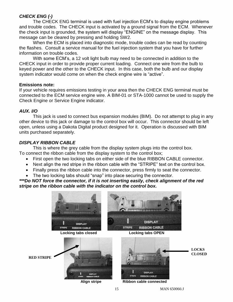
DISPLAY RIBBON CABLE
This is where the grey cable from the display system plugs into the control box. To connect the ribbon cable from the display system to the control box;
First open the two locking tabs on either side of the blue RIBBON CABLE connector.
Next align the red stripe in the ribbon cable with the “STRIPE” text on the control box.
Finally press the ribbon cable into the connector, press firmly to seat the connector.
The two locking tabs should “snap” into place securing the connector. ***Do NOT force the connector, if it is not inserting easily, check alignment of the red stripe on the ribbon cable with the indicator on the control box.
Locking tabs closed Locking tabs OPEN
Align stripe Ribbon cable connected
RED STRIPE
LOCKS
CLOSED
MAN 650066:J 16
Setting up the control box
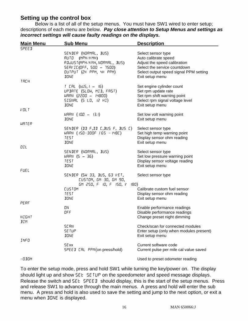
Below is a list of all of the setup menus. You must have SW1 wired to enter setup; descriptions of each menu are below. Pay close attention to Setup Menus and settings as incorrect settings will cause faulty readings on the displays.
Main Menu Sub Menu Description____________________ SPEED
SENDER (normal, bus) Select sensor type AUTO (MPH/KMH) Auto calibrate speed ADJUST(MPH/KMH, normal, bus) Adjust the speed calibration Servic(OFF, 500 – 7500) Select the service countdown OUTPUT (2k ppm, 4k PPm) Select output speed signal PPM setting
DONE Exit setup menu Tach
T CAL (,1 – 16) Set engine cylinder count UPDATE (slow, mid, fast) Set rpm update rate WARN (2200 – 14800) Set rpm shift warning point SIGNAL (5 LO, 12 HI) Select rpm signal voltage level DONE Exit setup menu
VOLT WARN (10.0 – 13.1) Set low volt warning point DONE Exit setup menu
WATER SENDER (DD F,DD C,BUS F, BUS C) Select sensor type WARN (150-300F / 65 -148c) Set high temp warning point TEST Display sensor ohm reading DONE Exit setup menu
OIL SENDER (normal, BUS) Select sensor type WARN (5 – 36) Set low pressure warning point TEST Display sensor voltage reading DONE Exit setup menu
FUEL SENDER (SW 33, BUS, 63 VET, Select sensor type
CUSTOM, GM 30, GM 90, GM 250, F 10, F 150, V 180)
CUSTOM Calibrate custom fuel sensor TEST Display sensor ohm reading DONE Exit setup menu
PERF On Enable performance readings Off Disable performance readings
NIGHT Change preset night dimming BIM SCAN Check/scan for connected modules SETUP Enter setup (only when modules present) DONE Exit setup menu INFO
SExx Current software code SPEED CAL PPM(on press/hold) Current pulse per mile cal value saved
-ODOM Used to preset odometer reading
To enter the setup mode, press and hold SW1 while turning the key/power on. The display
should light up and show SE SETUP on the speedometer and speed message displays.
Release the switch and SE SPEED should display, this is the start of the setup menus. Press and release SW1 to advance through the main menus. A press and hold will enter the sub menu. A press and hold is also used to save the setting and jump to the next option, or exit a menu when DONE is displayed.
MAN 650066:J 17
SPEEDOMETER SETUP/CALIBRATION There are two main methods for calibrating the speedometer, Auto Cal and Adjust. Auto
Cal requires that you have one measured mile marked out (1 km for metric). Adjust requires you to follow another vehicle going at a set speed, using a handheld GPS with speedometer function, or timing yourself over a mile to determine your speed. * It is simplest to start with the Auto Cal method to get the speedometer close. If you find it’s reading too fast/slow after the Auto Cal, then attempt the Adjust mode.
Press and hold SW1, then turn the key on and start the engine.
Once the engine is running, release SW1. SE SPEED should be displayed.
Press and hold the switch until - SPEED is displayed to go into the speed setup menus, release SW1.
Now you can press and release the switch to scroll through the sub-menus, “sender” “auto” “adjust” “Servic” “output” “DONE”. When you get to the desired sub-menu press and hold the switch to select it.
Speed sensor setup (SENDER) This menu is used to set the speed sensor input type. You can use the supplied pulse generator or existing speed sensor for most applications. You can also read the speed signal with the use of a bus interface module (BIM). Dakota Digital offers the BIM-01-X that will allow you to read the speed signal from an ECU if you are installing the system in a vehicle equipped with an OBDII diagnostic port or a drivetrain from a newer vehicle. Most 1996 and newer vehicles have this. If you are using a Dakota Digital pulse generator or feeding an ECU signal into the SPD SND terminal, this is considered a “normal” signal.
When “sender” is displayed, press and hold SW1 until you get “ - ”.
Release SW1 and the current sensor selection will be displayed.
Press and release SW1 to toggle between “normal” and “BUS”.
When the desired setting is displayed press and hold SW1 until “ - ” “DONE” is displayed.
Release the switch to go onto the next sub menu item. Auto Cal (AUTO) This menu is used to calibrate the speed signal by driving a measured mile (or kilometer)
When “AUTO” is displayed press and hold SW1 until you get “ - ”.
Release SW1 and the primary speed unit will be displayed.
Press and release SW1 to toggle between “MPH” for miles per hour or “KMH” for kilometers per hour. The setting saved here will be what the speedometer reads as well as the units used to calculate odometer reading.
When the desired unit is displayed, press and hold SW1 until you see the “ - ” then release SW1.
The speedometer will display “CAL” and the odometer should be reading “000000”, the other displays should be lit and display normally (fuel, volt, water, and oil). Begin driving the measured mile. The odometer reading should start incrementing as you travel, indicating the pulses received from the speed sensor or VSS. This is known as the pulses per mile (PPM). Once you reach the end of the marked mile, or are passing the marker, press and release SW1. The displays will flash off, then everything should light up and the speedometer should now be displaying your speed. Auto Cal is now complete and your speedometer should be reading correctly.
MAN 650066:J 18
(Auto Cal continued) NOTES: You do not have to drive at a constant speed nor do you have to avoid stopping during Auto Cal. When completed, you do not need to stop; you may, but you can also just press and release SW1 as you pass the one mile mark. The message display cannot be used to determine when the mile has been driven; it’s only there as a reference to indicate pulses are coming into the control box. Even if you have an 8000 PPM sensor you may calibrate at 9xxx PPM (for example) due to gearing and tire size. Also be aware that the odometer is calculated from the speedometer cal value; if it is not calibrated properly, the odometer reading could be higher/lower than actual. ***If you do not receive more than 2000 pulses during calibration the unit will error out. Adjust Mode (ADJUST) Adjust is different depending on what input signal is selected in the SENDER menu.
When “ADJUST” is displayed, press and hold SW1 until you get “ - ” then release the switch.
Now select the primary units by pressing and releasing SW1, “MPH” for miles per hour or “KMH” for kilometers per hour.
When the desired units are selected, press and hold SW1 until you see the “ - ” then release SW1.
If “normal” is selected for the sender type it will allow you to adjust the signal that is being supplied to the SPD SND terminal coming from a pulse generator or ECU. The fuel, volt, oil, water, and tach will operate normally. The speedometer will show the speed reading and the speed message display will say “ADJUST”. Begin driving at a known speed. Press and hold SW1 to increase the speedometer reading the next press and hold of SW1 will decrease the speedometer reading. You can continue adjusting up and down as needed until the reading is correct. When the speedometer is correct, stop and restart the system by turning the key/power off and then starting the vehicle back up. The new calibration will be saved when the power is shut off.
If “Bus” is selected for the sender type, the speed signal should be coming into the AUX I/O port through the use of a BIM module. The adjustment ratio ranges from 75 – 125% on this setting. It is assumed that the signal from the external device is the correct pulse rate so there are only provisions for slight adjustment. The odometer will light up and show “CL xx” xx is adjustable from 75 – 125 and is the percentage the input is corrected by. If set to 100 the signal is uncorrected and whatever the BIM module is reading is displayed on the dash. NOTES: For adjust mode you can follow another vehicle, time yourself, or use a GPS as a reference. A chassis dyno is another excellent way to use the Adjust mode. Also be aware that the odometer reading is calculated from the speedometer cal value and if not calibrated properly, the odometer reading could be higher/lower.
Service countdown meter (S-SET) The service countdown meter or, S-SET, allows you to set a distance value that will decrease as the odometer increases. When the value gets to zero, a message “S DUE” will appear on the message display on power up to remind you that service is due. This can be used for routine maintenance reminders such as oil changes.
When “S-SET” is displayed press and hold SW1 until you get “ - ” then release the switch. The current service setting will be displayed.
Press and release SW1 to increase the value from “OFF” then “500”-“7500” in 500 mile increments.
Once the desired setting is displayed, press and hold SW1 untill “ - ” “DONE” is displayed to save the value.
MAN 650066:J 19
Speed Output (OUTPUT) If a speed signal is needed for an ECM or cruise control, the SPD OUT terminal can be
used. This terminal can supply a 2000 ppm or 4000 ppm signal. If a BIM-01-X is used to supply the speedometer reading, this output is not available.
When “output” is displayed, press and hold SW1 until you get “ - ”.
Release the switch. The current PPM output will be displayed.
Press and release SW1 to toggle from “ 2k PPM” to “ 4k PPM”.
When the desired setting is displayed, press and hold SW1 until “ - ” “DONE” is displayed.
Release the switch to go onto the next menu item. Exit setup (done)
This will allow you to exit the speed setup and go on to the next setup menu.
When “Sedone” is displayed, press and hold SW1 until you get “ - DONE ”.
Release the switch to go onto the next menu.
TACHOMETER SETUP
The control box can be set to read from 1-16 cylinder ignition signals. It can also be set to read either 12 volt tach signals or 5 volt tach signals found on some engine computers. The digital tachometer update rate can be adjusted between slow, mid, and fast. The rpm warning/shift point can be adjusted from 2200 – 14800. The tachometer will read from 350 – 17,500 rpm. At RPM above 9990 the reading will be displayed as rpmx1000 (12,000=12.00).
You can also read the tach signal with the use of a bus interface module (BIM). Dakota Digital offers the BIM-01-X that will allow you to read the RPM from an ECU if you are installing the system in a vehicle equipped with the OBDII diagnostic port or a drivetrain from a newer vehicle. Most 1996 and newer vehicles have this.
Press and hold SW1 while turning the key on.
Release the switch and then press and release SW1 to get to the “TACH” setup menu.
Press and hold the switch until “- tach” is displayed to enter the tach setup menus, then release SW1.
Now you can press and release the switch to scroll through the tach sub-menus, “T CAL” “UPDATE” “WARN” “SIGNAL” “DONE”.
When you get to the desired sub-menu, press and hold the switch to select it.
Engine cylinder setup (T-CAL) This menu is used to set the cylinder count of the tach signal. It is adjustable from 1 -16 cylinders.
When “T-CAL” is displayed, press and hold SW1 until you see “ - ”.
Release SW1 and the current cylinder setting will be displayed.
Press and release SW1 to increase the value from “ 01 ” – “ 16 ” or “ ”.
When the desired setting is displayed, press and hold SW1 until “ - ” “DONE” is displayed
Release the switch to go onto the next menu item.
NOTE: When selecting the cylinder count, be aware of tach signals coming from ECMs, oftentimes a V-8 engine computer may output a 4 cylinder tach signal. This will be set for “ 04 ” not “ 08 ” as you might expect.
MAN 650066:J 20
Display update setup (UPDATE) The display update rate can be adjusted so the reading on the tachometer doesn’t change so quickly. This is a personal preference and is used to “slow” the reading by averaging. The value can be changed from slow, mid, or fast.
When “UPDATE” is displayed, press and hold SW1 until you get “ - ”.
Release SW1 and the current update rate will be displayed.
Press and release SW1 to increase the value from “SLOw” “ MID” “ FAST”.
When the desired setting is displayed, press and hold SW1 until “ - ” “DONE” is displayed.
Release the switch to go onto the next sub-menu item.
RPM warning setup (WARN) This is used for the turn on point for the WARN output on the control box. When the RPM reading is above this setting, the output will activate, providing a ground signal. It can be used to turn on a shift light or other RPM based devices. The value is adjustable from 2200 RPM – 14800 RPM in 100 RPM increments.
When “WARN” is displayed press and hold SW1 until you get “ - ”.
Release SW1 and the current warning point will be displayed.
Press and release SW1 to increase the value from “W 2200” – “W14800”.
When the desired setting is displayed press and hold SW1 until “ - ” “DONE” is displayed.
Release the switch to go onto the next sub-menu item.
Tach signal setup (SIGNAL) This menu will allow you to select from two different tach-input types. A low voltage, “5 LO”, tach signal or a high voltage tach signal, “12 HI”. A low voltage signal is usually one picked up from the ECM. Low voltage may also be considered a 0-5V square wave. If you are getting the tach signal from the ignition coil or points, set this for the high voltage signal“12 HI”. To pick up a tach signal from a traditional coil wire the tach input to the negative side of the coil.
When “signal” is displayed press and hold SW1 until you get “ - ”.
Release SW1 and the current value will be displayed.
Press and release SW1 to toggle from “12 HI” to “5 LO”.
When the desired setting is displayed, press and hold SW1 until “ - ” “DONE” is displayed.
Release the switch to go onto the next sub-menu item.
Exit tach setup (done) This will allow you to exit the tach setup and go on to the next setup menu.
When “Sedone” is displayed, press and hold SW1 until you get “ - DONE ”.
Release the switch to go onto the next menu.
VOLT SETUP The Volt setup allows you set a warning point that will cause the Volt display to flash
whenever the voltage drops below the warning value. The low voltage point can be set from 10 -13.1 volts.
Press and hold SW1 while turning the key on.
Release the switch and then press and release SW1 to get to the “volt” setup menu.
When “volt” is displayed press and hold SW1 until you get “ - ”, release SW1 and “WARN” will be displayed.
When “WARN” is displayed press and hold SW1 until you get “ - ”.
Release SW1 and the current warning point will be displayed.
Press and release SW1 to increase the value from “LO 10.0” – “LO 13.1”.
When the desired setting is displayed, press and hold SW1 until “ - ” “DONE” is displayed.
Release the switch to go onto the next sub-menu item.
MAN 650066:J 21
WATER TEMP SETUP
The Water Temp setup allows you to select the units the temperature is displayed in, Fahrenheit or Celsius. It also allows you to set a high temperature warning point that will cause the display to flash whenever the reading on the display is higher than the set point. There is also a test mode that will display the resistance for the sensor for trouble shooting assistance.
Press and hold SW1 while turning the key on.
Release the switch and then press and release SW1 to get to the “water” setup menu.
Press and hold the switch until “-” “water” is displayed to enter the water setup menus, then release SW1.
Now you can press and release the switch to scroll through the water sub-menus, “SENDER” “WARN” “test” “DONE”.
When you get to the desired sub-menu press and hold the switch to select it.
Temp sensor setup (SENDER) This menu is used to set the temp sensor type. Dakota Digital only offers one temp sensor for this system, it is SEN-04-5, 100-300 F(40-150 C), 1/8” NPT threads. You can use bushings to adapt the sensor to various locations. You will select “DD F” to read in Fahrenheit, or select “DD C” to read in Celsius.
You can also read the temp with the use of a bus interface module (BIM). Dakota Digital offers the BIM-01-X that will allow you to read the engine temp signal from an ECU if you are installing the system in a vehicle equipped with an OBDII diagnostic port or a drivetrain from a newer vehicle. Most 1996 and newer vehicles have this. You will select “BUS F” to read in Fahrenheit, or select “BUS C” to read in Celsius.
When “sender” is displayed press and hold SW1 until you get “ - ”.
Release SW1 and the current sensor selection will be displayed.
Press and release SW1 to scroll through the sensor options “DD F” “DD C” “BUS F” “BUS C”.
When the desired setting is displayed press and hold SW1 until “ - ” “DONE” is displayed.
Release the switch to go onto the next sub- menu item. Temp warning setup (WARN) This menu will allow you to select the high temperature warning point. When the display value is higher than this point, the WATER display will flash. The value is adjustable from 150 – 300 F (65-148 C).
When “WARN” is displayed, press and hold SW1 until you get “ - ”.
Release SW1 and the current warning point will be displayed.
Press and release SW1 to increase the value from “H 150F” – “H 300F”.
When the desired value is displayed, press and hold SW1 until “ - ” “DONE” is displayed.
Release the switch to go onto the next sub-menu item.
MAN 650066:J 22
Temp sensor test (test) This menu will allow you to check the resistance the control box is reading from the water temp sensor. This can be used for a diagnostic tool if you are having trouble or feel that the reading is incorrect. For the Dakota Digital SEN-04-5, the resistance decreases as temperature increases. Typical values for the Dakota Digital SEN-04-5 sensor are: 100F = 500 ohms, 200F = 75 ohms, and 300F = 19 ohms
If the gauge reads “” this is an open connection or no sensor connected. If it is reading “ ” this is an indication of a short.
When “test” is displayed, press and hold SW1 until you get “ - ”.
Release SW1 and the current resistance from the temp sensor will be displayed on the speedometer and “R TEMP” is displayed on the odometer readout.
Press and release SW1 to scroll through the next sensor input if you wish “v oil” “R fuel” “R temp”.
Once complete, hold SW1 until “ - ” “DONE” is displayed.
Release the switch to go onto the next sub-menu item. Exit water temp setup (done)
This will allow you to exit the water temp setup and go on to the next setup menu.
When “Sedone” is displayed, press and hold SW1 until you get “ - DONE ”
Release the switch to go onto the next menu.
OIL PRESSURE SETUP
Dakota Digital only offers one pressure sensor for this system, SEN-03-8, 0-100 psi solid state sensor with 1/8” NPT threads. This is the sender “NORMAL” selection. If “BUS” is selected for the sender type, the oil pressure reading should be coming into the AUX I/O port through the use of a BIM module. The oil pressure setup allows you to set up a low pressure warning point that will cause the display to flash whenever the reading on the display is lower than the set point. There is also a test mode that will display the voltage from the sensor for trouble shooting assistance.
Press and hold SW1 while turning the key on.
Release the switch, then press and release SW1 to enter the “OIL” setup menu.
Press and hold the switch until “ - ” “oil” is displayed to enter the oil pressure setup menus, then release SW1.
Press and release the switch to scroll through the oil sub-menus, “WARN” “test” “DONE”. When you get to the desired sub-menu, press and hold the switch to select it.
Oil pressure sender setup (SENDER) This menu will allow you to select the oil pressure sender being used. “NORMAL” selects the supplied SEN-03-8 sensor. “BUS” allows for reading the oil pressure from a BIM module in a compatible vehicle.
When “SENDER” is displayed, press and hold SW1 until you get “ - ”.
Release SW1 and the current selection will be displayed.
Press and release SW1 to change between “normal” and “bus”.
When the desired value is displayed press and hold SW1 until “ ” “DONE” is displayed.
Release the switch to go onto the next menu item.
MAN 650066:J 23
Oil pressure warning setup (WARN) This menu will allow you to select the low pressure warning point. When the display value is lower than this point, the OIL display will flash. The value is adjustable from 5 – 36 psi.
When “WARN” is displayed, press and hold SW1 until you get “ - ”
Release SW1 and the current warning point will be displayed.
Press and release SW1 to increase the value from “LO 05” – “lo 36”
When the desired value is displayed press and hold SW1 until “ - ” “DONE” is displayed.
Release the switch to go onto the next menu item.
Oil pressure sensor test (test) This menu will allow you to check the voltage the control box is reading from the pressure sensor. This can be used for a diagnostic tool if you are having trouble or feel that the reading is incorrect. For the Dakota Digital SEN-03-8, 0-100 psi sensor, the voltage increases with pressure. At 0 psi, the voltage should be close to 0.5V at 100 psi the voltage should be close to 4.5V.
When “test” is displayed, press and hold SW1 until you get “ - ”
Release SW1 and the current voltage from the pressure sensor will be displayed on the speedometer and “V OIL” is displayed on the odometer readout.
Press and release SW1 to scroll through the next sensor input if you wish “R FUEL” “R temp” “v oil”
Once complete, hold SW1 until “ - ” “DONE” is displayed.
Release the switch to go onto the next sub-menu item.
Exit oil pressure setup (done) This will allow you to exit the oil pressure setup and go on to the next setup menu.
When “Sedone” is displayed, press and hold SW1 until you get “ - DONE ”
Release the switch to go onto the next menu.
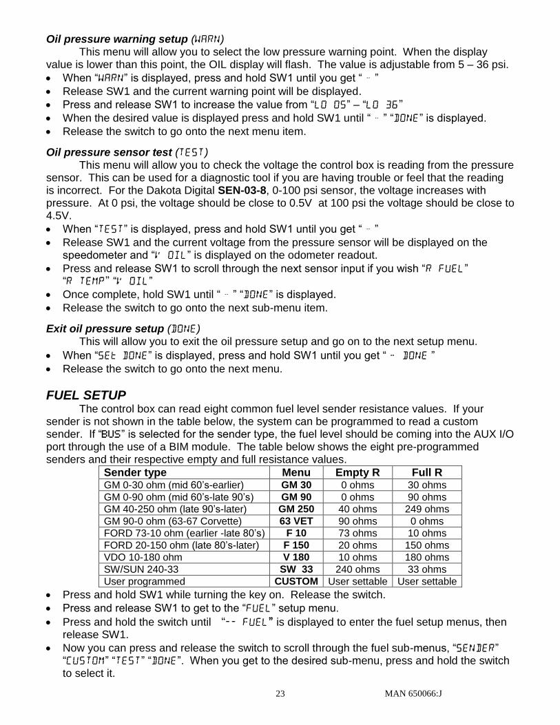
FUEL SETUP
The control box can read eight common fuel level sender resistance values. If your sender is not shown in the table below, the system can be programmed to read a custom sender. If “BUS” is selected for the sender type, the fuel level should be coming into the AUX I/O port through the use of a BIM module. The table below shows the eight pre-programmed senders and their respective empty and full resistance values.
Sender type Menu Empty R Full R GM 0-30 ohm (mid 60’s-earlier) GM 30 0 ohms 30 ohms
GM 0-90 ohm (mid 60’s-late 90’s) GM 90 0 ohms 90 ohms
GM 40-250 ohm (late 90’s-later) GM 250 40 ohms 249 ohms
GM 90-0 ohm (63-67 Corvette) 63 VET 90 ohms 0 ohms
FORD 73-10 ohm (earlier -late 80’s) F 10 73 ohms 10 ohms
FORD 20-150 ohm (late 80’s-later) F 150 20 ohms 150 ohms
VDO 10-180 ohm V 180 10 ohms 180 ohms
SW/SUN 240-33 SW 33 240 ohms 33 ohms
User programmed CUSTOM User settable User settable
Press and hold SW1 while turning the key on. Release the switch.
Press and release SW1 to get to the “FUEL” setup menu.
Press and hold the switch until “fuel” is displayed to enter the fuel setup menus, then release SW1.
Now you can press and release the switch to scroll through the fuel sub-menus, “SENDER” “custom” “test” “DONE”. When you get to the desired sub-menu, press and hold the switch to select it.
MAN 650066:J 24
Fuel sensor setup (SENDER) This menu is used to select the fuel level sensor type. The table above shows the seven options and resistance ranges as well as the custom option. Note: You need to calibrate the custom sensor to your specific fuel sensor if you are using this option in the custom setup in the steps below.
When “sender” is displayed, press and hold SW1 until you get “ - ”
Release SW1 and the current sensor selection will be displayed.
Press and release SW1 to scroll through the sensor options “gm 30” “gm 90” “GM 250” “f 10” “f 150” “v 180” “sw 33” “Bus” “63 vet” “custom”
When the desired setting is displayed, press and hold SW1 until “ - ” “DONE” is displayed.
Release the switch to go onto the next menu item.
Custom fuel sender curve setup (custom) You will need to have the sender out of the tank, or begin with the tank empty and add fuel during the custom fuel sender setup. *** The factory default custom curve is 110 empty and 5 ohms full
When “CUSTOM” is displayed, press and hold SW1 until you get “ - ”
Release SW1 and the speed display will show the current sender resistance as read by the control box.
The message display will show “SET 00”. Move the float to the empty position and then press and release the SW1.
The message display will show “SET 33”. Move the float to 1/3 full and then press and release the SW1.
The message display will show “SET 66”. Move the float to 2/3 full and then press and release the SW1.
The message display will show “SET 99”. Move the float to the full position and then press and release the SW1. The new sender is now stored under the “CUSTOM” sender selection.
The message display will be back in the fuel sub-menu showing “test”. ***If the resistances recorded during custom calibration are not in sequence you will get a “FAIL” message at the end of calibration. No values will be saved and calibration must be started again. Make sure the resistance of the sensor is linear from empty to full.
Note: Once the custom sender is programmed, go back and ensure that “custom” is selected in the “SENDER” menu. Programming the custom sender curve does not automatically make it the ‘active’ sender.
Fuel sensor test (test) This menu will allow you to check the resistance the control box is reading from the fuel level sensor. This can be used as a diagnostic tool if you are having trouble or feel that the reading is incorrect. You can use the table of fuel sensors above to get an idea of the resistance you should be seeing.
When “test” is displayed, press and hold SW1 until you get “ - ”
Release SW1 and the current resistance from the fuel level sensor will be displayed on the speedometer and “R fuel” is displayed on the odometer readout.
Press and release SW1 to scroll through the next sensor input if you wish “R temp”, “v oil”, “R fuel”
Once complete, hold SW1 until “ - ” “DONE” is displayed.
Release the switch to go onto the next sub-menu item. Note: Fuel level sensors are generally not precise; in the test function you should expect to see some error. For instance a GM 0-90 sensor may display 5 ohms empty and 97 ohms full. If you are within 10% of the values in the table, this is considered within specification.
MAN 650066:J 25
Exit fuel setup (done)
This will allow you to exit the fuel setup and go on to the next setup menu.
When “Sedone” is displayed press and hold SW1 until you get “ - DONE ”
Release the switch to go onto the next menu
PERFORMANCE MENU SETUP
The performance menus can be turned on or off, allowing you to scroll through the message screens quicker. All of the performance functions are displayed from information that is already wired to the control box, so disabling will not save any wiring steps.
Press and hold SW1 while turning the key on.
Release the switch and then press and release SW1 to get to the “perf” setup menu.
Press and hold the switch until “-” “perf” is displayed to enter the setup menu, then release SW1.
Now you can press and release the switch to toggle from “”(allowing the performance
readings to be shown), or “”(disabling, hiding the performance readings).
When the desired option is displayed; press and hold SW1 until you get “ - DONE ”
Release the switch to go onto the next menu. NOTE: In normal operation you have to use SW1 to reset the various performance timers. A press and hold will zero the current reading, if it can be reset.
NIGHTTIME DIM SETUP
The nighttime dim menu, “NIGHT”, allows you to set the brightness level that the instrument system will dim down to when the DIM terminal has power applied to it.
If you are using the separately purchased DIM-1kit from Dakota Digital, this brightness level doesn’t matter as you have total control of the brightness level with the twist of a knob. Using the ADJ SND and ADJ – terminals, this setting will be overridden by the DIM-1 knob.
Press and hold SW1 while turning the key on.
Release the switch and then press and release SW1 to get to the “night” setup menu.
Press and hold the switch until “-” “night” is displayed to enter the setup menu, then release SW1.
Now you can press and release the switch to gradually dim the displays (you can press and hold SW1 and the displays will cycle from bright to dim)
When the desired brightness level is achieved, press and release SW2 to save the brightness level and go on to the next setup menu.
MAN 650066:J 26
BUS INTERFACE MODULE SETUP
The bus interface modules (BIM) can be added to Dakota Digital instrumentation systems. They allow you to add auxiliary gauge functions such as fuel pressure, vac/boost, trans temp, etc., right into the system without having to add additional gauges. All of the BIM readings are displayed on the tachometer message display where the tachometer and other performance readings are currently displayed. Switch 2 (SW2) is used to cycle through the various message screens.
More detailed instructions are supplied with the BIM units.
INFORMATION MENU The information menu “INFO” is used to display software code information should you
have any trouble this information can be useful for troubleshooting as well as the current speedometer calibration value if using the normal speed input (SPD SND).
Press and hold SW1 while turning the key on.
Release the switch and then press and release SW1 to get to the “INFO” setup menu. You should see “SExx” on the speedometer display where xx is the software number.
To view the current pulse per mile (PPM) setting, press and hold the SW1 until “-” “INFO” is displayed.
Release the switch and the odometer will show the current PPM setting/calibration value.
Press and release the switch to go on to the next setup menu.
ODOMETER PRESET MENU
The control box will allow you to set the odometer reading to match your current odometer reading, ONE time within the first 100 miles. Once the odometer has more than 100 miles, this menu option will no longer be displayed. Make sure you have correctly selected the units to be either MPH or km/h and calibrated your speedometer first. The odometer will be set in the selected units. Once you have preset the miles you cannot change it again without sending to the factory.
WARNING!!: This only allows setting odometer to the nearest mile. Do not use tenths!
For example a mileage of 65432.1 should be set to “” using this method. If the tenths digit is used, the odometer will read 10 times too high.
Press and hold SW1 while turning the key on.
Release the switch and then press and release SW1 to get to the “-odom” setup menu.
Press and hold the switch until “-” “odom” is displayed to enter the odometer setup menu, then release SW1. The current miles will be displayed on the odometer with the left most digit flashing.
Press and release SW1 to increment the digit. Press and hold the switch to move to the next digit to the right.
Continue until the right most digit has been set. Press and hold the switch and the speed
display will show “ ”
If the value is incorrect, press and hold the switch while “ ” is displayed to go back and change the odometer miles or turn the key off to cancel any changes.
If the value is correct, press and release the switch to change to speed display to “”.
Press and hold the switch while “” is displayed to save the current odometer reading and return to the setup menus.
MAN 650066:J 27
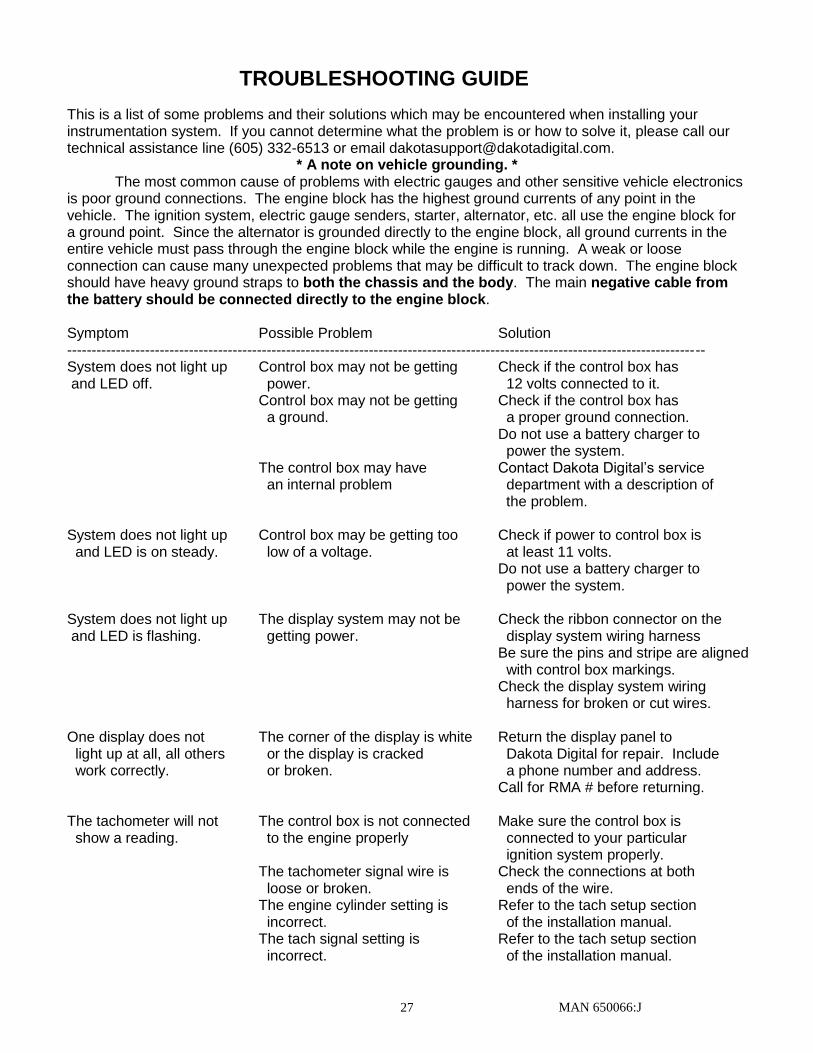
TROUBLESHOOTING GUIDE
This is a list of some problems and their solutions which may be encountered when installing your instrumentation system. If you cannot determine what the problem is or how to solve it, please call our technical assistance line (605) 332-6513 or email [email protected].
* A note on vehicle grounding. * The most common cause of problems with electric gauges and other sensitive vehicle electronics is poor ground connections. The engine block has the highest ground currents of any point in the vehicle. The ignition system, electric gauge senders, starter, alternator, etc. all use the engine block for a ground point. Since the alternator is grounded directly to the engine block, all ground currents in the entire vehicle must pass through the engine block while the engine is running. A weak or loose connection can cause many unexpected problems that may be difficult to track down. The engine block should have heavy ground straps to both the chassis and the body. The main negative cable from the battery should be connected directly to the engine block. Symptom Possible Problem Solution ----------------------------------------------------------------------------------------------------------------------------------- System does not light up Control box may not be getting Check if the control box has and LED off. power. 12 volts connected to it. Control box may not be getting Check if the control box has a ground. a proper ground connection. Do not use a battery charger to power the system. The control box may have Contact Dakota Digital’s service an internal problem department with a description of the problem. System does not light up Control box may be getting too Check if power to control box is and LED is on steady. low of a voltage. at least 11 volts. Do not use a battery charger to power the system. System does not light up The display system may not be Check the ribbon connector on the and LED is flashing. getting power. display system wiring harness Be sure the pins and stripe are aligned with control box markings. Check the display system wiring harness for broken or cut wires. One display does not The corner of the display is white Return the display panel to light up at all, all others or the display is cracked Dakota Digital for repair. Include work correctly. or broken. a phone number and address. Call for RMA # before returning. The tachometer will not The control box is not connected Make sure the control box is show a reading. to the engine properly connected to your particular ignition system properly. The tachometer signal wire is Check the connections at both loose or broken. ends of the wire. The engine cylinder setting is Refer to the tach setup section incorrect. of the installation manual. The tach signal setting is Refer to the tach setup section incorrect. of the installation manual.
MAN 650066:J 28
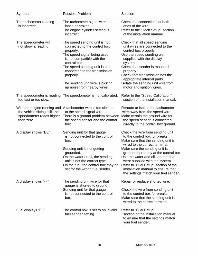
Symptom Possible Problem Solution ----------------------------------------------------------------------------------------------------------------------------------- The tachometer reading The tachometer signal wire is Check the connections at both is incorrect. loose or broken. ends of the wire. The engine cylinder setting is Refer to the “Tach Setup” section incorrect. of the installation manual. The speedometer will The speed sending unit is not Check that all speed sending not show a reading. connected to the control box unit wires are connected to the properly. control box properly. The speed signal being used Use the speed sending unit is not compatible with the supplied with the display control box. system. The speed sending unit is not Check that sender is mounted connected to the transmission properly. properly. Check that transmission has the appropriate internal parts. The sending unit wire is picking Isolate the sending unit wire from up noise from nearby wires. motor and ignition wires. The speedometer is reading The speedometer is not calibrated. Refer to the “Speed Calibration” too fast or too slow. section of the installation manual. With the engine running and A tachometer wire is too close to Reroute or isolate the tachometer the vehicle sitting still, the to the speed signal wire. wire away from the speed wire. speedometer reads higher There is a ground problem between Make certain the ground wire for than zero. the speed sensor and the control the speed sensor is connected box. directly to the control box ground. A display shows “EE” Sending unit for that gauge Check the wire from sending unit is not connected to the control to the control box for breaks. box. Make sure that the sending unit is wired to the correct terminal. Sending unit is not getting Make sure the sending unit is grounded. grounded properly at the control box. On the water or oil, the sending Use the water and oil senders that unit is not the correct type. were supplied with the system. On the fuel, the control box may be Refer to “Fuel Setup” section of the set for the wrong fuel sender. installation manual to ensure that the settings match your fuel sender. A display shows “- -” The sending unit wire for that Repair or replace shorted wire. gauge is shorted to ground. Sending unit for that gauge Check the wire from sending unit is not connected to the control to the control box for breaks. box. Make sure that the sending unit is wired to the correct terminal. Fuel displays “FL” The control box is set to an invalid Refer to “Fuel Setup” fuel sender setting. section of the installation manual to ensure that the settings match your fuel sender.
MAN 650066:J 29
Symptom Possible Problem Solution ----------------------------------------------------------------------------------------------------------------------------------- The fuel display reads The control box may be set for Refer to “Fuel Setup” backwards, incorrectly, the wrong type of fuel sender. section of the installation manual or does not change. to ensure that the settings match your fuel sender. The fuel sender may not be Check the connections at both connected to the control box ends of the fuel sender wire. properly. Make sure the fuel sender is grounded properly. The fuel sender may not be Check the fuel sending unit with operating properly. an electrical multi-meter. The fuel sender may have a Use the custom fuel sender setup. non-standard resistance See the “Fuel Setup” section of the range. manual for instructions. The oil or water display The sending units are not grounded Make sure wires are in correct terminals. reading is incorrect. to the control box. The sending unit wire is picking Isolate the sending unit wire from up noise from nearby wires. motor and ignition wires. The sending unit is not Use the sending unit provided with compatible with the control box the display system. The gear shift indicator The optional gear shift sending Connect the sending unit to the does not light up. unit is not connected to the control box using the control box. instructions supplied with the sending unit. The gear shift indicator The gear shift decoder Check the connections to the does not operate is not connected properly. transmission linkage and to properly. the control box. The gear shift decoder is not Check gear shift decoder calibrated properly. Installation manual. The internal turn signal The control box is not connected Check the wires connected to the and high beam to the vehicle's electrical HIGH, LEFT, and RIGHT indicators do not light up. system properly. terminals on the control box. The Check Engine The control box is not connected This feature is designed to work indicator does not to an engine control module. with engine control systems that operate properly. provide an active low signal.
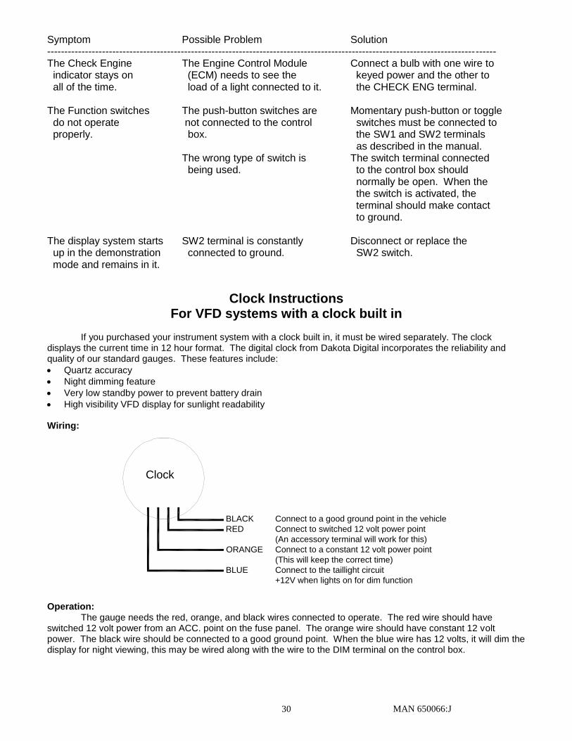
MAN 650066:J 30
Symptom Possible Problem Solution ----------------------------------------------------------------------------------------------------------------------------------- The Check Engine The Engine Control Module Connect a bulb with one wire to indicator stays on (ECM) needs to see the keyed power and the other to all of the time. load of a light connected to it. the CHECK ENG terminal. The Function switches The push-button switches are Momentary push-button or toggle do not operate not connected to the control switches must be connected to properly. box. the SW1 and SW2 terminals as described in the manual. The wrong type of switch is The switch terminal connected being used. to the control box should normally be open. When the the switch is activated, the terminal should make contact to ground. The display system starts SW2 terminal is constantly Disconnect or replace the up in the demonstration connected to ground. SW2 switch. mode and remains in it.
Clock Instructions For VFD systems with a clock built in
If you purchased your instrument system with a clock built in, it must be wired separately. The clock
displays the current time in 12 hour format. The digital clock from Dakota Digital incorporates the reliability and quality of our standard gauges. These features include:
Quartz accuracy
Night dimming feature
Very low standby power to prevent battery drain
High visibility VFD display for sunlight readability
Wiring:
Clock
BLACK Connect to a good ground point in the vehicle
RED Connect to switched 12 volt power point
(An accessory terminal will work for this)
ORANGE Connect to a constant 12 volt power point
(This will keep the correct time)
BLUE Connect to the taillight circuit
+12V when lights on for dim function
Operation:
The gauge needs the red, orange, and black wires connected to operate. The red wire should have switched 12 volt power from an ACC. point on the fuse panel. The orange wire should have constant 12 volt power. The black wire should be connected to a good ground point. When the blue wire has 12 volts, it will dim the display for night viewing, this may be wired along with the wire to the DIM terminal on the control box.
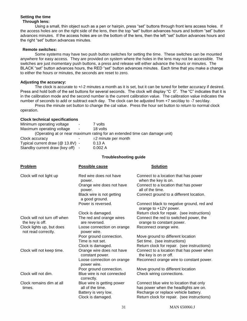
MAN 650066:J 31
Setting the time Through lens:
Using a small, thin object such as a pen or hairpin, press “set” buttons through front lens access holes. If the access holes are on the right side of the lens, then the top “set” button advances hours and bottom “set” button advances minutes. If the access holes are on the bottom of the lens, then the left “set” button advances hours and the right “set” button advances minutes. Remote switches:
Some systems may have two push button switches for setting the time. These switches can be mounted anywhere for easy access. They are provided on system where the holes in the lens may not be accessible. The switches are just momentary push buttons, a press and release will either advance the hours or minutes. The BLACK “set” button advances hours, the RED “set” button advances minutes. Each time that you make a change to either the hours or minutes, the seconds are reset to zero.
Adjusting the accuracy:
The clock is accurate to +/-2 minutes a month as it is set, but it can be tuned for better accuracy if desired. Press and hold both of the set buttons for several seconds. The clock will display “C 0”. The “C” indicates that it is in the calibration mode and the second number is the current calibration value. The calibration value indicates the number of seconds to add or subtract each day. The clock can be adjusted from +7 sec/day to -7 sec/day.
Press the minute set button to change the cal value. Press the hour set button to return to normal clock operation.
Clock technical specifications Minimum operating voltage - 7 volts Maximum operating voltage - 18 volts (Operating at or near maximum rating for an extended time can damage unit)
Clock accuracy - 2 minute per month Typical current draw (@ 13.8V) - 0.13 A Standby current draw (key off) - 0.002 A
Troubleshooting guide
Problem Possible cause Solution Clock will not light up Red wire does not have Connect to a location that has power power. when the key is on. Orange wire does not have Connect to a location that has power power. all of the time. Black wire is not getting Connect ground to a different location. a good ground. Power is reversed. Connect black to negative ground, red and orange to +12V power. Clock is damaged. Return clock for repair. (see instructions) Clock will not turn off when The red and orange wires Connect the red to switched power, the the key is off. are reversed. orange to constant power. Clock lights up, but does Loose connection on orange Reconnect orange wire. not read correctly. power wire. Poor ground connection. Move ground to different location Time is not set. Set time. (see instructions) Clock is damaged. Return clock for repair. (see instructions) Clock will not keep time. Orange wire does not have Connect to a location that has power when constant power. the key is on or off. Loose connection on orange Reconnect orange wire to constant power. power wire. Poor ground connection. Move ground to different location Clock will not dim. Blue wire is not connected Check wiring connections. correctly. Clock remains dim at all Blue wire is getting power Connect blue wire to location that only times. all of the time. has power when the headlights are on. Battery is very low. Recharge or replace vehicle battery. Clock is damaged. Return clock for repair. (see instructions)
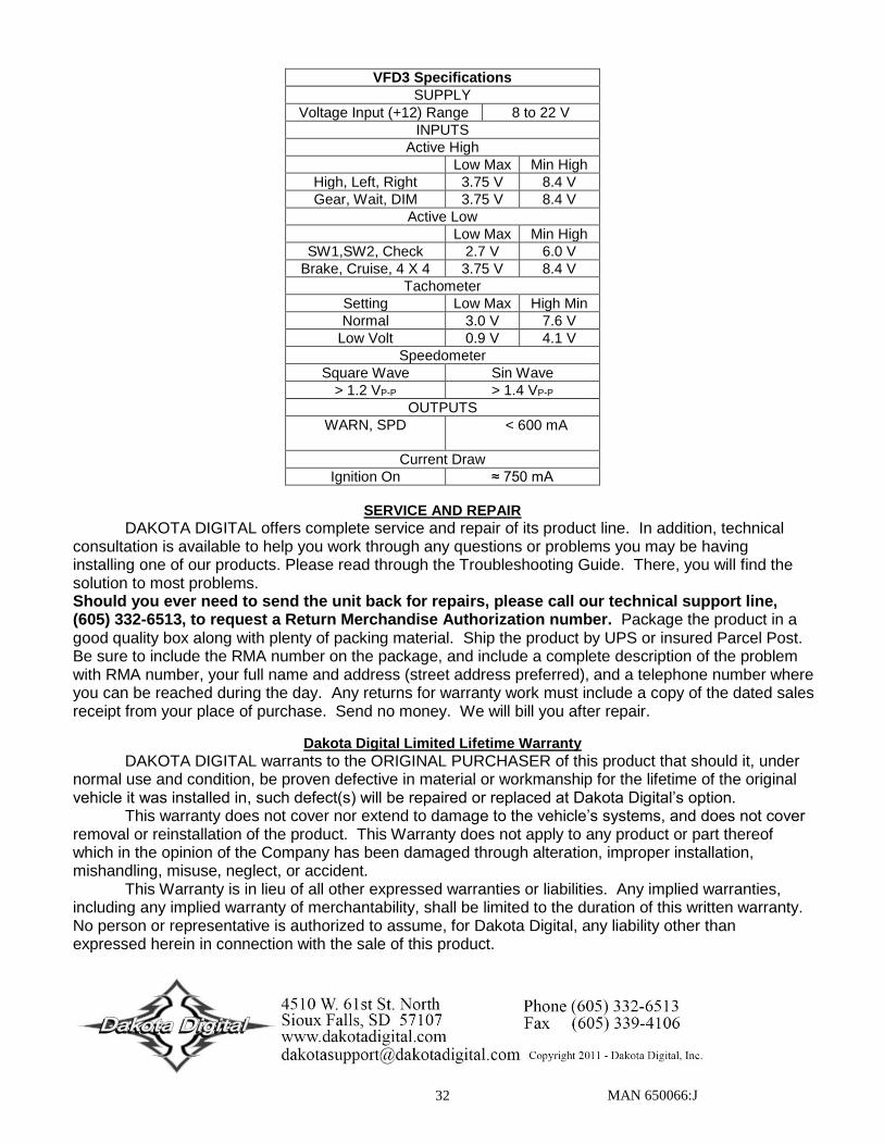
MAN 650066:J 32
VFD3 Specifications
SUPPLY
Voltage Input (+12) Range 8 to 22 V
INPUTS
Active High
Low Max Min High
High, Left, Right 3.75 V 8.4 V
Gear, Wait, DIM 3.75 V 8.4 V
Active Low
Low Max Min High
SW1,SW2, Check 2.7 V 6.0 V
Brake, Cruise, 4 X 4 3.75 V 8.4 V
Tachometer
Setting Low Max High Min
Normal 3.0 V 7.6 V
Low Volt 0.9 V 4.1 V
Speedometer
Square Wave Sin Wave
> 1.2 VP-P > 1.4 VP-P
OUTPUTS
WARN, SPD < 600 mA
Current Draw
Ignition On ≈ 750 mA
SERVICE AND REPAIR
DAKOTA DIGITAL offers complete service and repair of its product line. In addition, technical consultation is available to help you work through any questions or problems you may be having installing one of our products. Please read through the Troubleshooting Guide. There, you will find the solution to most problems. Should you ever need to send the unit back for repairs, please call our technical support line, (605) 332-6513, to request a Return Merchandise Authorization number. Package the product in a good quality box along with plenty of packing material. Ship the product by UPS or insured Parcel Post. Be sure to include the RMA number on the package, and include a complete description of the problem with RMA number, your full name and address (street address preferred), and a telephone number where you can be reached during the day. Any returns for warranty work must include a copy of the dated sales receipt from your place of purchase. Send no money. We will bill you after repair.
Dakota Digital Limited Lifetime Warranty
DAKOTA DIGITAL warrants to the ORIGINAL PURCHASER of this product that should it, under normal use and condition, be proven defective in material or workmanship for the lifetime of the original vehicle it was installed in, such defect(s) will be repaired or replaced at Dakota Digital’s option.
This warranty does not cover nor extend to damage to the vehicle’s systems, and does not cover removal or reinstallation of the product. This Warranty does not apply to any product or part thereof which in the opinion of the Company has been damaged through alteration, improper installation, mishandling, misuse, neglect, or accident.
This Warranty is in lieu of all other expressed warranties or liabilities. Any implied warranties, including any implied warranty of merchantability, shall be limited to the duration of this written warranty. No person or representative is authorized to assume, for Dakota Digital, any liability other than expressed herein in connection with the sale of this product.


![6. Wiring Diagram - weidefamily.net coil Transmission control module ... WIRING DIAGRAM 6. Wiring Diagram. MEMO: 21 WIRING DIAGRAM ... 76 6-3 [D6R2] WIRING DIAGRAM 6](https://img.pdfslide.us/doc/110x75/5aa0cc3b7f8b9a62178ea5e7/6-wiring-diagram-coil-transmission-control-module-wiring-diagram-6-wiring.jpg)