Embed Size (px)
Citation preview
Information Brochure
Choose controlsto match
application
1 Application BrochureDesign your mechanical applications
2 Rough InWiring
Rough-inwiring
instructions
3 WiringBrochureWiring and
installation of specific control
4 DataBrochure
Control settings and sequence of
operation
5 JobRecord
Record settings & wiring details for future reference
6
W 480 09/09tekmarNet®4 User Switch 480
- Wiring Brochure
1 of 8 © 2009 W 480 - 09/09
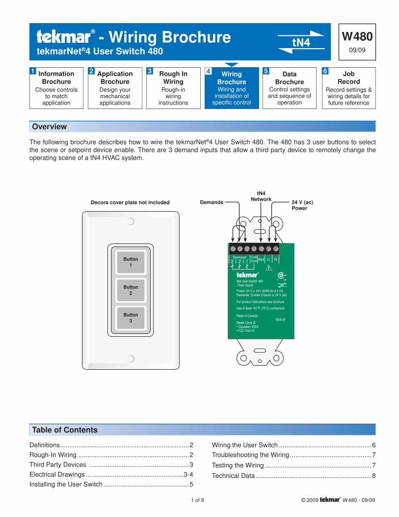
The following brochure describes how to wire the tekmarNet®4 User Switch 480. The 480 has 3 user buttons to select the scene or setpoint device enable. There are 3 demand inputs that allow a third party device to remotely change the operating scene of a tN4 HVAC system.
Definitions .......................................................................2
Rough-In Wiring .............................................................2
Third Party Devices .......................................................3
Electrical Drawings ......................................................3-4
Installing the User Switch ...............................................5
Wiring the User Switch ...................................................6
Troubleshooting the Wiring .............................................7
Testing the Wiring ...........................................................7
Technical Data ................................................................8
Table of Contents
Overview
Button1
Button2
Button3
Power: 24 V ± 10% 50/60 Hz 2.2 VADemands: Contact Closure or 24 V (ac)
tN4 User Switch 480Three Inputs
Made in Canada1009-01
For product instructions see brochure
Use at least 167°F (75°C) conductors
Meets Class B:• Canadian ICES• FCC Part 15
Com2 13 Dem
DemandRCtN4
tN4Network 24 V (ac)
PowerDemandsDecora cover plate not included
© 2009 W480 - 09/09 2 of 8
Defi nitions
The following defined terms and symbols are used throughout this manual to bring attention to the presence of hazards of various risk levels, or to important information concerning the life of the product.
– Caution: Refer to accompanying documents.
– Caution: Refer to accompanying documents.
INSTALLATIONCATEGORY II – Local level appliances.
Caution
Improper installation and operation of this control could result in damage to the equipment and possibly even personal injury or death. It is your responsibility to ensure that this control is safely installed according to all applicable
codes and standards. Do not attempt to service the control. Refer to qualified personnel for servicing. Disassembly of the control voids warranty and could result in damage to the equipment.
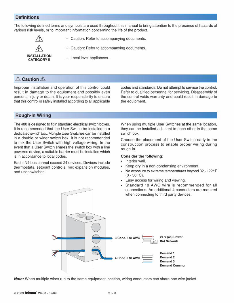
Rough-In Wiring
The 480 is designed to fit in standard electrical switch boxes. It is recommended that the User Switch be installed in a dedicated switch box. Multiple User Switches can be installed in a double or wider switch box. It is not recommended to mix the User Switch with high voltage wiring. In the event that a User Switch shares the switch box with a line powered device, a suitable barrier must be installed which is in accordance to local codes.
Each tN4 bus cannot exceed 24 devices. Devices include thermostats, setpoint controls, mix expansion modules, and user switches.
When using multiple User Switches at the same location, they can be installed adjacent to each other in the same switch box.
Choose the placement of the User Switch early in the construction process to enable proper wiring during rough-in.
Consider the following:• Interior wall.
• Keep dry in a non-condensing environment.
• No exposure to extreme temperatures beyond 32 - 122°F (0 - 50°C).
• Easy access for wiring and viewing.
• Standard 18 AWG wire is recommended for all connections. An additional 4 conductors are required when connecting to third party devices.
3 Cond. / 18 AWG 24 V (ac) PowertN4 Network
Demand 1Demand 2Demand 3Demand Common
4 Cond. / 18 AWG
Note: When multiple wires run to the same equipment location, wiring conductors can share one wire jacket.
3 of 8 © 2009 W480 - 09/09
Third Party Devices
The 480 is designed to provide inputs from third party devices such as:• Telephone switches
• Automation systems
• Security alarm systems
It is up to the installer to determine if a particular third party device is compatible with the 480.
For suggestions on compatible third party devices, please contact your tekmar sales representative.
Electrical Drawings
The electrical drawing examples on the following pages show the 480 in common applications. These drawings have a brief explanation of what is being operated in each system. Choose the components in your system and use the drawings as a guide to aid in wiring your system.
These are only concept drawings, not engineered drawings. They are not intended to describe a complete system nor any particular system. It is up to the system designer to determine the necessary components for and configuration of the particular system being designed including additional equipment isolation relays (for loads greater than the controls specified output ratings) and any safety devices which in the judgment of the designer are appropriate in order to properly size, configure and design that system and to ensure compliance with building and safety code requirements.
© 2009 W480 - 09/09 4 of 8
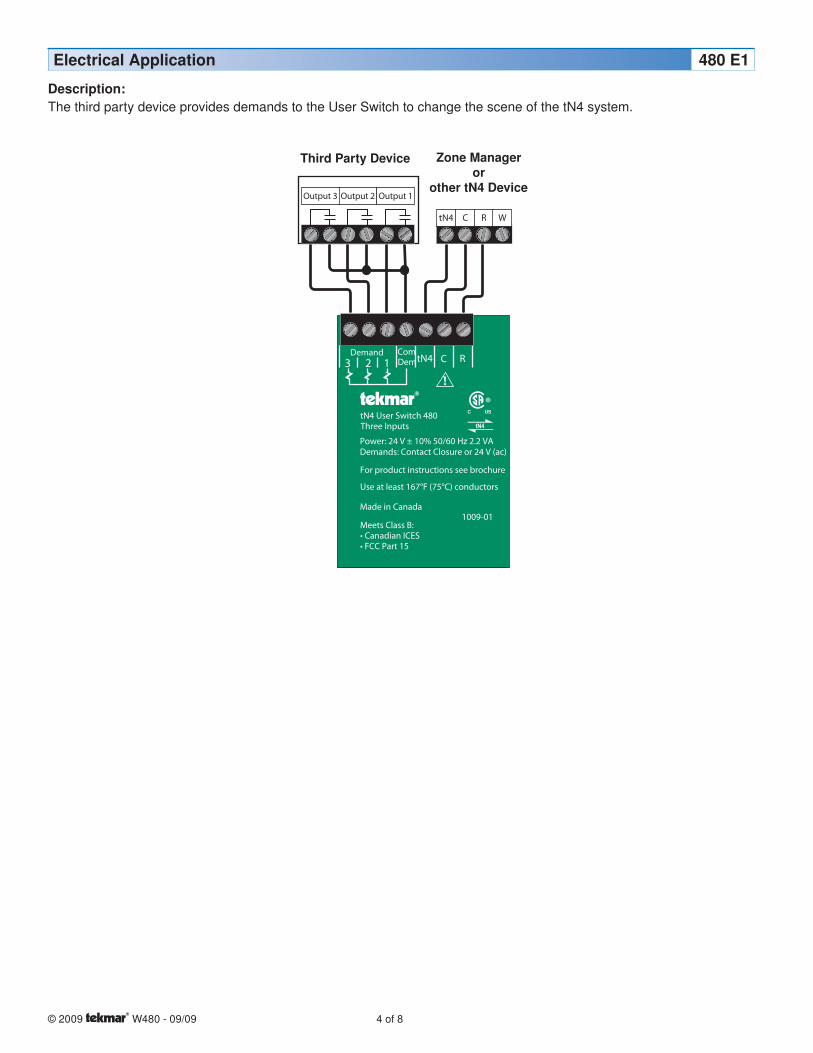
Electrical Application 480 E1
Description:The third party device provides demands to the User Switch to change the scene of the tN4 system.
C R WtN4
Power: 24 V ± 10% 50/60 Hz 2.2 VADemands: Contact Closure or 24 V (ac)
tN4 User Switch 480Three Inputs
Made in Canada1009-01
For product instructions see brochure
Use at least 167°F (75°C) conductors
Meets Class B:• Canadian ICES• FCC Part 15
Com2 13 Dem
DemandRCtN4
Output 3 Output 2 Output 1
5 of 8 © 2009 W480 - 09/09
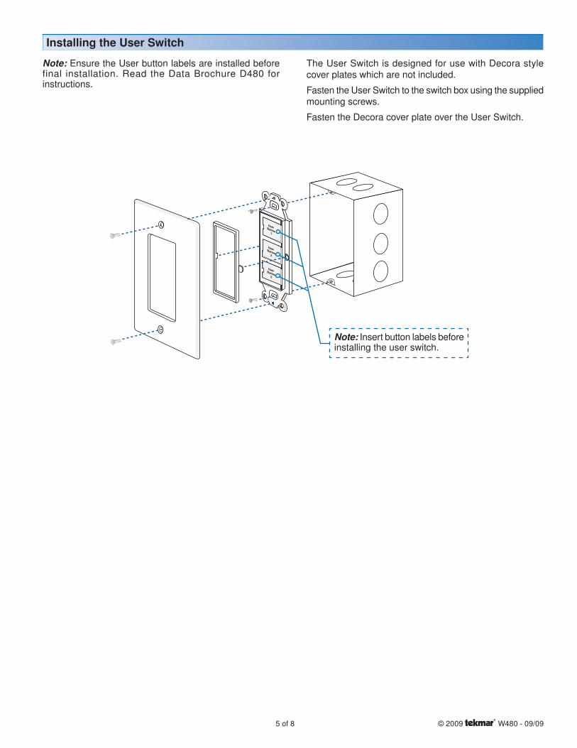
Installing the User Switch
Note: Ensure the User button labels are installed before final installation. Read the Data Brochure D480 for instructions.
The User Switch is designed for use with Decora style cover plates which are not included.
Fasten the User Switch to the switch box using the supplied mounting screws.
Fasten the Decora cover plate over the User Switch.
UserButton1
UserButton2
UserButton2
Note: Insert button labels before installing the user switch.
© 2009 W480 - 09/09 6 of 8
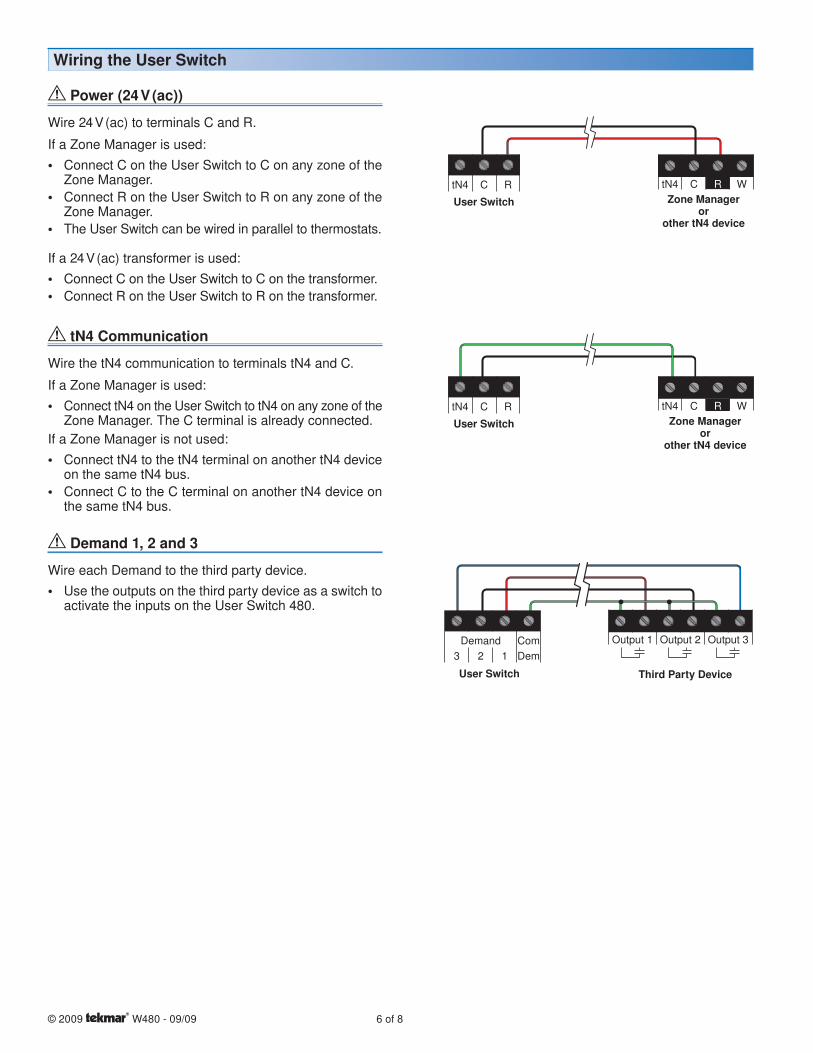
tN4 Communication
Wire the tN4 communication to terminals tN4 and C.
If a Zone Manager is used:
• Connect tN4 on the User Switch to tN4 on any zone of the Zone Manager. The C terminal is already connected.
If a Zone Manager is not used:
• Connect tN4 to the tN4 terminal on another tN4 device on the same tN4 bus.
• Connect C to the C terminal on another tN4 device on the same tN4 bus.
Demand 1, 2 and 3
Wire each Demand to the third party device.
• Use the outputs on the third party device as a switch to activate the inputs on the User Switch 480.
User Switch Zone Manageror
other tN4 device
tN4 C R WtN4 C R
User Switch Third Party Device
Demand Com
3 2 1 Dem
Output 1 Output 2 Output 3
Wiring the User Switch
Power (24 V (ac))
Wire 24 V (ac) to terminals C and R.
If a Zone Manager is used:
• Connect C on the User Switch to C on any zone of the Zone Manager.
• Connect R on the User Switch to R on any zone of the Zone Manager.
• The User Switch can be wired in parallel to thermostats.
If a 24 V (ac) transformer is used:
• Connect C on the User Switch to C on the transformer.
• Connect R on the User Switch to R on the transformer.
User Switch Zone Manageror
other tN4 device
tN4 C R WtN4 C R
7 of 8 © 2009 W480 - 09/09
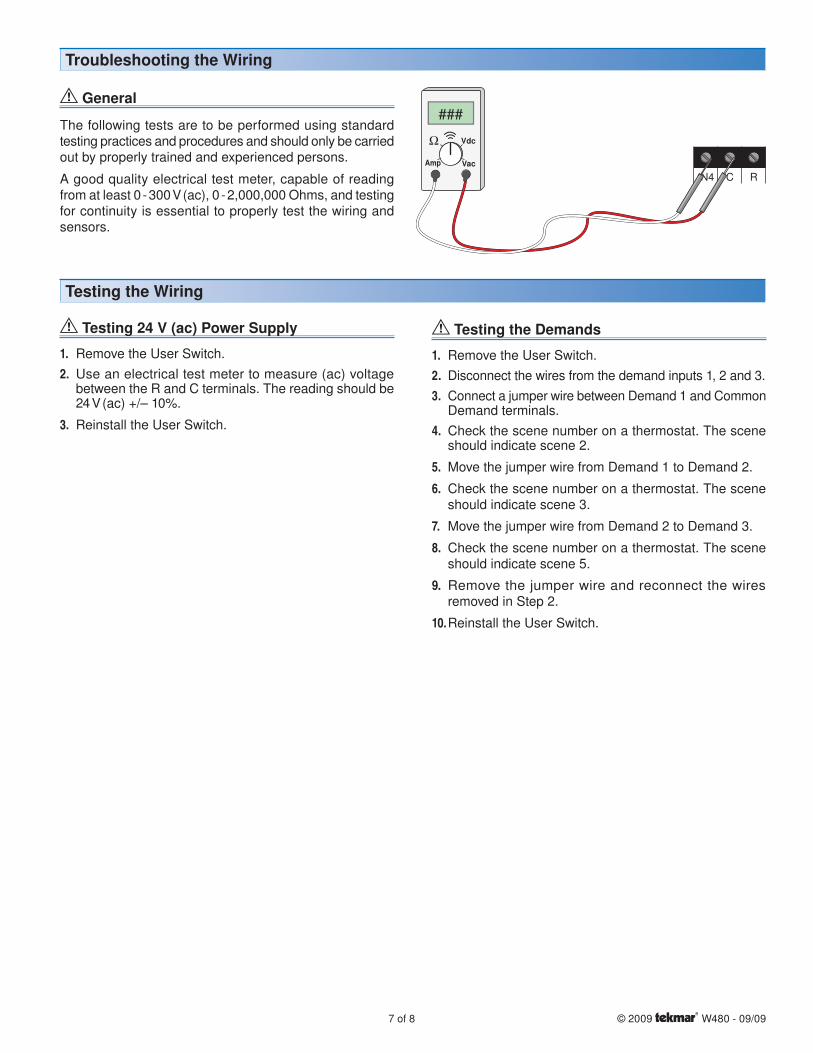
Troubleshooting the Wiring
General
The following tests are to be performed using standard testing practices and procedures and should only be carried out by properly trained and experienced persons.
A good quality electrical test meter, capable of reading from at least 0 - 300 V (ac), 0 - 2,000,000 Ohms, and testing for continuity is essential to properly test the wiring and sensors.
tN4 C R
###
Testing the Wiring
Testing 24 V (ac) Power Supply
1. Remove the User Switch.
2. Use an electrical test meter to measure (ac) voltage between the R and C terminals. The reading should be 24 V (ac) +/– 10%.
3. Reinstall the User Switch.
Testing the Demands
1. Remove the User Switch.
2. Disconnect the wires from the demand inputs 1, 2 and 3.
3. Connect a jumper wire between Demand 1 and Common Demand terminals.
4. Check the scene number on a thermostat. The scene should indicate scene 2.
5. Move the jumper wire from Demand 1 to Demand 2.
6. Check the scene number on a thermostat. The scene should indicate scene 3.
7. Move the jumper wire from Demand 2 to Demand 3.
8. Check the scene number on a thermostat. The scene should indicate scene 5.
9. Remove the jumper wire and reconnect the wires removed in Step 2.
10. Reinstall the User Switch.
Technical Data
tekmar Control Systems Ltd., Canadatekmar Control Systems, Inc., U.S.A.Head Office: 5100 Silver Star RoadVernon, B.C. Canada V1B 3K4(250) 545-7749 Fax. (250) 545-0650Web Site: www.tekmarcontrols.com
Product design, software and literature are Copyright © 2009 by:tekmar Control Systems Ltd. and tekmar Control Systems, Inc.
8 of 8All specifications are subject to change without notice.
Printed in Canada. W 480 - 09/09.
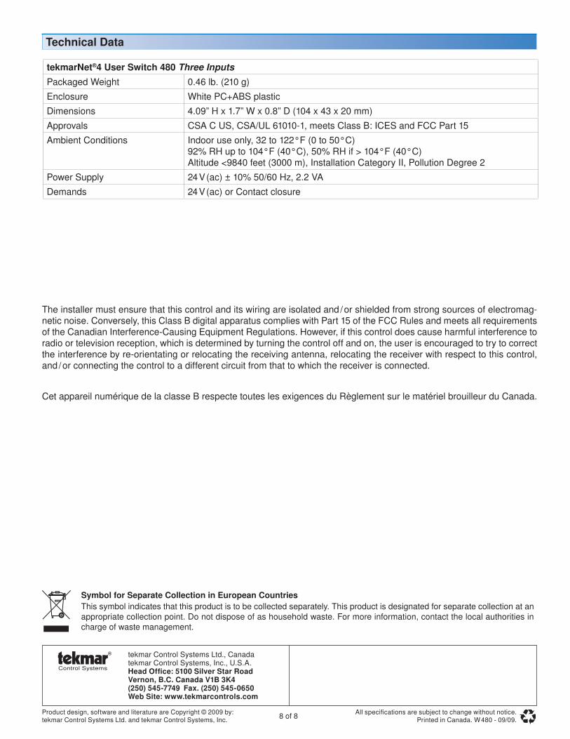
The installer must ensure that this control and its wiring are isolated and / or shielded from strong sources of electromag-netic noise. Conversely, this Class B digital apparatus complies with Part 15 of the FCC Rules and meets all requirements of the Canadian Interference-Causing Equipment Regulations. However, if this control does cause harmful interference to radio or television reception, which is determined by turning the control off and on, the user is encouraged to try to correct the interference by re-orientating or relocating the receiving antenna, relocating the receiver with respect to this control, and / or connecting the control to a different circuit from that to which the receiver is connected.
Cet appareil numérique de la classe B respecte toutes les exigences du Règlement sur le matériel brouilleur du Canada.
tekmarNet®4 User Switch 480 Three InputsPackaged Weight 0.46 lb. (210 g)
Enclosure White PC+ABS plastic
Dimensions 4.09” H x 1.7” W x 0.8” D (104 x 43 x 20 mm)
Approvals CSA C US, CSA/UL 61010-1, meets Class B: ICES and FCC Part 15
Ambient Conditions Indoor use only, 32 to 122°F (0 to 50°C)92% RH up to 104°F (40°C), 50% RH if > 104°F (40°C)Altitude <9840 feet (3000 m), Installation Category II, Pollution Degree 2
Power Supply 24 V (ac) ± 10% 50/60 Hz, 2.2 VA
Demands 24 V (ac) or Contact closure
Symbol for Separate Collection in European CountriesThis symbol indicates that this product is to be collected separately. This product is designated for separate collection at an appropriate collection point. Do not dispose of as household waste. For more information, contact the local authorities in charge of waste management.


![BROCHURE Wiring ducts Easily allows for …...5 — Wiring ducts Halogen free wiring ducts with vertical slots Product code GID Number Width [mm] Height [mm] Weight [Kg/m] Pack [metres]](https://img.pdfslide.us/doc/110x75/5e908828126c866950671267/brochure-wiring-ducts-easily-allows-for-5-a-wiring-ducts-halogen-free-wiring.jpg)