Embed Size (px)
Citation preview
Bell Labs Technical Journal ◆ July–September 1998 79
IntroductionTraditional telephony uses circuit-switching tech-
nology, in which necessary resources such as bearer
channels are allocated by the network for the duration
of a phone call. In contrast, voice-over-Internet proto-
col (IP) employs packet-switching technology, which
decomposes voice into IP packets. Each packet is then
transmitted over an IP network and reassembled at
the other end without pre-allocating any circuit con-
nections. While the recent rise of voice-over-IP as an
alternative to circuit-switched telephony may indicate
the dawn of a new era for wired telephony (such as
the recent interest in international calling via IP net-
works), many questions remain in the area of wireless
voice and data services for Advanced Mobile Phone
Service (AMPS) and personal communications ser-
vices (PCS). For example:
• Will wireless voice-over-IP gain momentum in
a way similar to its wireline counterpart?
• What are the implications for the design of
third-generation (3G) wireless systems, whose
standards are being defined as part of the
International Mobile Telecommunications
♦ Wireless Voice-over-IP and Implications forThird-Generation Network DesignJin Wang, Peter J. McCann, Patvardhana B. Gorrepati, and Chung-Zin Liu
The recent rise of voice-over-Internet protocol (IP) as an alternative to circuit-basedtelephony poses some serious questions to the wireless community. Will wirelessvoice-over-IP and multimedia-over-IP gain momentum over their circuit-based alter-natives? Should the design of third-generation (3G) wireless systems take these alter-natives into account? In this paper we describe two models of wireless voice-over-IPand discuss additional requirements necessary to support business-grade-qualityvoice in the face of mobility. The case studies we present assumed an air interface ofIS-95 code division multiple access (CDMA) or IS-136 time division multiple access(TDMA). The results of our studies show that business-grade voice-over-IP may notbe economical for the licensed cellular and personal communications services (PCS)radio spectrum because the cost of licensing the cellular/PCS radio spectrum is highand the circuit-mode air interface is already efficient. To compete in various markets,however, 3G networks should efficiently support both wireless voice-over-IP andmultimedia-over-IP. To do this, 3G networks should meet the challenge of seamlesspacket data handoffs and deep compression of user data protocol (UDP)/IP headers.Efficient support for wireless multimedia-over-IP may be even more critical (com-pared to voice-over-IP) for helping packet-based 3G multimedia such as H.323 tocompete with its broadband integrated services digital network (B-ISDN) counter-part. As wireless voice and data converge in the 3G world, betting on packet-datamobility in addition to voice mobility may be a key to enabling the wireless industryto fuel the explosive growth of mobile subscribers worldwide.
80 Bell Labs Technical Journal ◆ July–September 1998
2000 (IMT-2000) effort within the
International Telecommunication Union (ITU)?
In this paper, we describe two models of wireless
voice-over-IP, followed by a discussion of additional
requirements necessary to support business-grade-
quality voice services in the face of mobility. Within
this discussion, we briefly describe the concept of the
IMT-2000 “family of systems” and the 3G network-to-
network interface (NNI) in the context of packet-data
mobility. Next we examine some basic economics of
the AMPS/PCS wireless business that uses the licensed
radio-frequency (RF) spectrum. We then present two
case studies: the IS-95 code division multiple access
(CDMA)1 and the IS-136 time division multiple access
(TDMA).2 CDMA and TDMA represent the major cir-
cuit-mode voice technologies of the AMPS/PCS wire-
less business using licensed radio spectrum. The results
of our studies show that business-grade voice-over-IP
may not be economical for the licensed cellular/PCS
radio spectrum because the cost of licensing the radio
spectrum is high and the circuit-mode air interface is
already efficient. Increased global competition in vari-
ous markets, however, makes it important for 3G net-
works to efficiently support both wireless
voice-over-IP and multimedia-over-IP. To accomplish
this goal, 3G networks should meet the challenge of
seamless packet data handoffs and deep compression
of user data protocol (UDP)/IP headers. After summa-
rizing the two case studies, we discuss other implica-
tions for 3G network design.
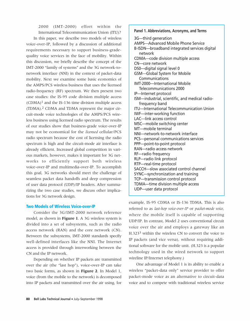
Two Models of Wireless Voice-over-IPConsider the 3G/IMT-2000 network reference
model, as shown in Figure 1. A 3G wireless system is
divided into a set of subsystems, such as the radio
access network (RAN) and the core network (CN).
Between the subsystems, IMT-2000 standards specify
well-defined interfaces like the NNI. The Internet
access is provided through interworking between the
CN and the IP network.
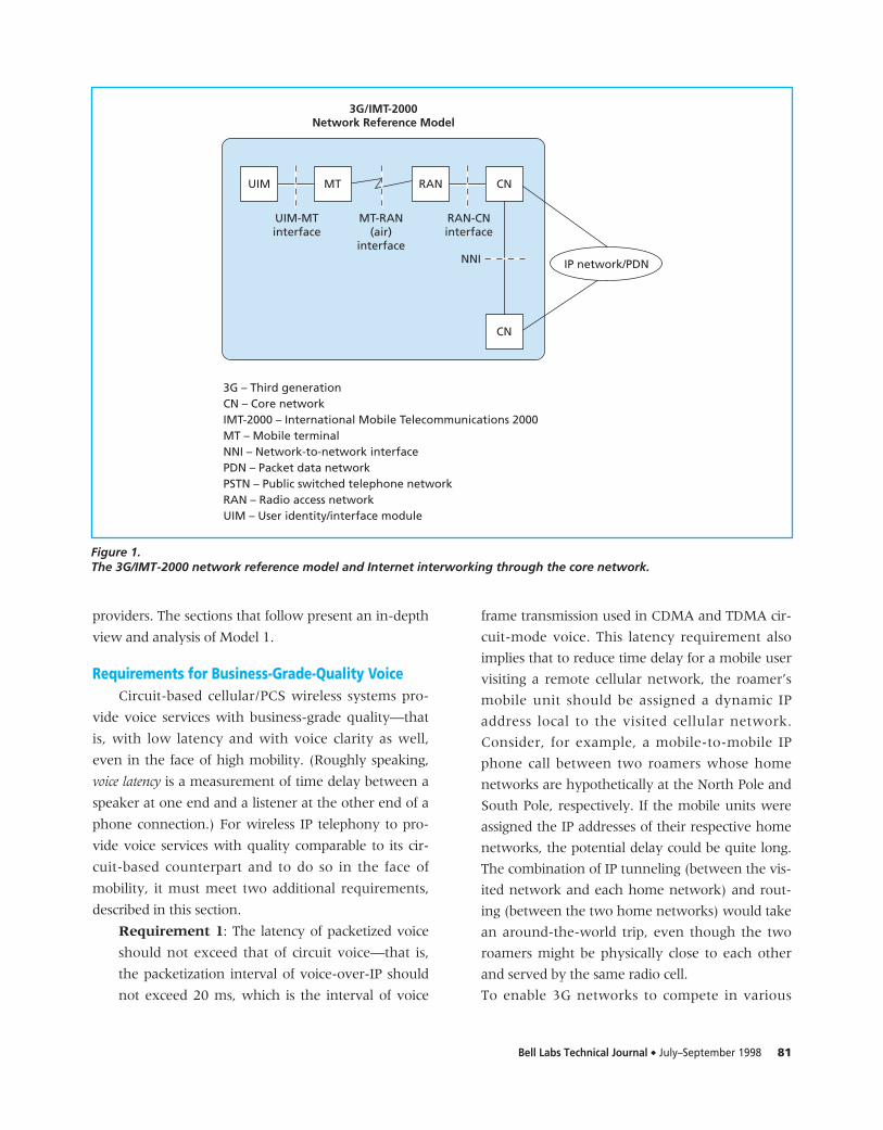
Depending on whether IP packets are transmitted
over the air (the “last hop”), voice-over-IP can take
two basic forms, as shown in Figure 2. In Model 1,
voice (from the mobile to the network) is decomposed
into IP packets and transmitted over the air using, for
example, IS-95 CDMA or IS-136 TDMA. This is also
referred to as last-hop voice-over-IP or packet-mode voice,
where the mobile itself is capable of supporting
UDP/IP. In contrast, Model 2 uses conventional circuit
voice over the air and employs a gateway like an
H.3233 within the wireless CN to convert the voice to
IP packets (and vice versa), without requiring addi-
tional software for the mobile unit. (H.323 is a popular
technology used in the wired network to support
wireline IP/Internet telephony.)
One advantage of Model 1 is its ability to enable a
wireless “packet-data only” service provider to offer
packet-mode voice as an alternative to circuit-data
voice and to compete with traditional wireless service
Panel 1. Abbreviations, Acronyms, and Terms
3G—third generationAMPS—Advanced Mobile Phone ServiceB-ISDN—broadband integrated services digital
networkCDMA—code division multiple accessCN—core networkDS0—digital signal level 0GSM—Global System for Mobile
CommunicationsIMT-2000—International Mobile
Telecommunications 2000IP—Internet protocolISM—industrial, scientific, and medical radio-
frequency bandITU—International Telecommunication UnionIWF—inter-working functionLAC—link access controlMSC—mobile switching centerMT—mobile terminalNNI—network-to-network interfacePCS—personal communications servicesPPP—point-to-point protocolRAN—radio access networkRF—radio frequencyRLP—radio link protocolRTP—real-time protocolSACCH—slow associated control channelSYNC—synchronization and trainingTCP—transmission control protocolTDMA—time division multiple accessUDP—user data protocol
Bell Labs Technical Journal ◆ July–September 1998 81
providers. The sections that follow present an in-depth
view and analysis of Model 1.
Requirements for Business-Grade-Quality VoiceCircuit-based cellular/PCS wireless systems pro-
vide voice services with business-grade quality—that
is, with low latency and with voice clarity as well,
even in the face of high mobility. (Roughly speaking,
voice latency is a measurement of time delay between a
speaker at one end and a listener at the other end of a
phone connection.) For wireless IP telephony to pro-
vide voice services with quality comparable to its cir-
cuit-based counterpart and to do so in the face of
mobility, it must meet two additional requirements,
described in this section.
Requirement 1: The latency of packetized voice
should not exceed that of circuit voice—that is,
the packetization interval of voice-over-IP should
not exceed 20 ms, which is the interval of voice
frame transmission used in CDMA and TDMA cir-
cuit-mode voice. This latency requirement also
implies that to reduce time delay for a mobile user
visiting a remote cellular network, the roamer’s
mobile unit should be assigned a dynamic IP
address local to the visited cellular network.
Consider, for example, a mobile-to-mobile IP
phone call between two roamers whose home
networks are hypothetically at the North Pole and
South Pole, respectively. If the mobile units were
assigned the IP addresses of their respective home
networks, the potential delay could be quite long.
The combination of IP tunneling (between the vis-
ited network and each home network) and rout-
ing (between the two home networks) would take
an around-the-world trip, even though the two
roamers might be physically close to each other
and served by the same radio cell.
To enable 3G networks to compete in various
UIM MT RAN CN
UIM-MTinterface
MT-RAN(air)
interface
RAN-CNinterface
3G/IMT-2000Network Reference Model
CN
NNI IP network/PDN
3G – Third generationCN – Core networkIMT-2000 – International Mobile Telecommunications 2000MT – Mobile terminalNNI – Network-to-network interfacePDN – Packet data networkPSTN – Public switched telephone networkRAN – Radio access networkUIM – User identity/interface module
Figure 1.The 3G/IMT-2000 network reference model and Internet interworking through the core network.
82 Bell Labs Technical Journal ◆ July–September 1998
markets and to make the first model of voice-over-IP
viable, 3G network designers should consider the fol-
lowing design guideline:
3G Network Design Guideline 1: If applications
like voice-over-IP and multimedia-over-IP are impor-
tant, 3G systems should be designed to support the types
of applications that require low end-to-end latency.
The guideline above implies that 3G networks
should support short packetization intervals and
dynamic IP address assignment by both visited and
home wireless networks and should manage IP-related
resources efficiently.
Requirement 2: Packet data handoffs that must
be performed as a user is moving or drifting
around should be as seamless as those made for
circuit voice, with minimum packet loss. This
ensures that regardless of whether circuit voice or
packet voice is used, the mobile user will always
experience the same or similar voice quality, even
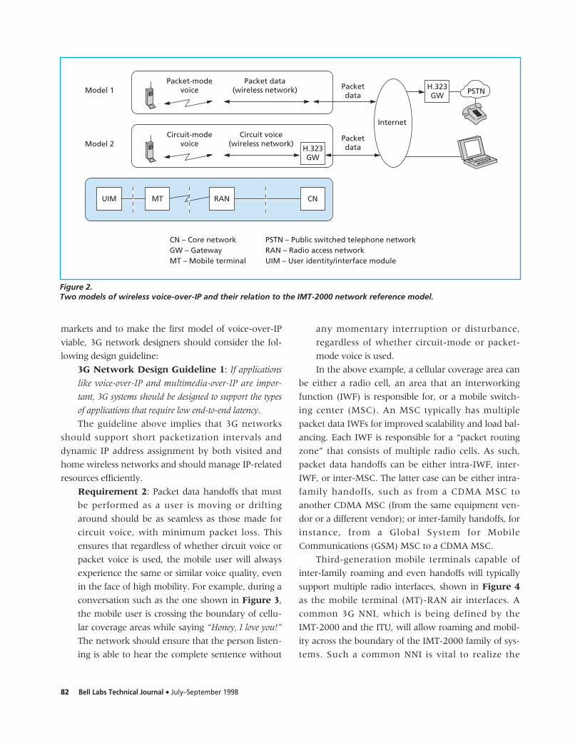
in the face of high mobility. For example, during a
conversation such as the one shown in Figure 3,
the mobile user is crossing the boundary of cellu-
lar coverage areas while saying “Honey, I love you!”
The network should ensure that the person listen-
ing is able to hear the complete sentence without
any momentary interruption or disturbance,
regardless of whether circuit-mode or packet-
mode voice is used.
In the above example, a cellular coverage area can
be either a radio cell, an area that an interworking
function (IWF) is responsible for, or a mobile switch-
ing center (MSC). An MSC typically has multiple
packet data IWFs for improved scalability and load bal-
ancing. Each IWF is responsible for a “packet routing
zone” that consists of multiple radio cells. As such,
packet data handoffs can be either intra-IWF, inter-
IWF, or inter-MSC. The latter case can be either intra-
family handoffs, such as from a CDMA MSC to
another CDMA MSC (from the same equipment ven-
dor or a different vendor); or inter-family handoffs, for
instance, from a Global System for Mobile
Communications (GSM) MSC to a CDMA MSC.
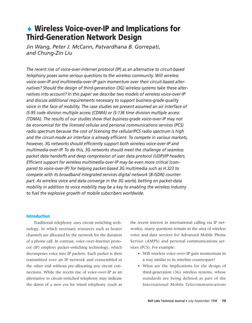
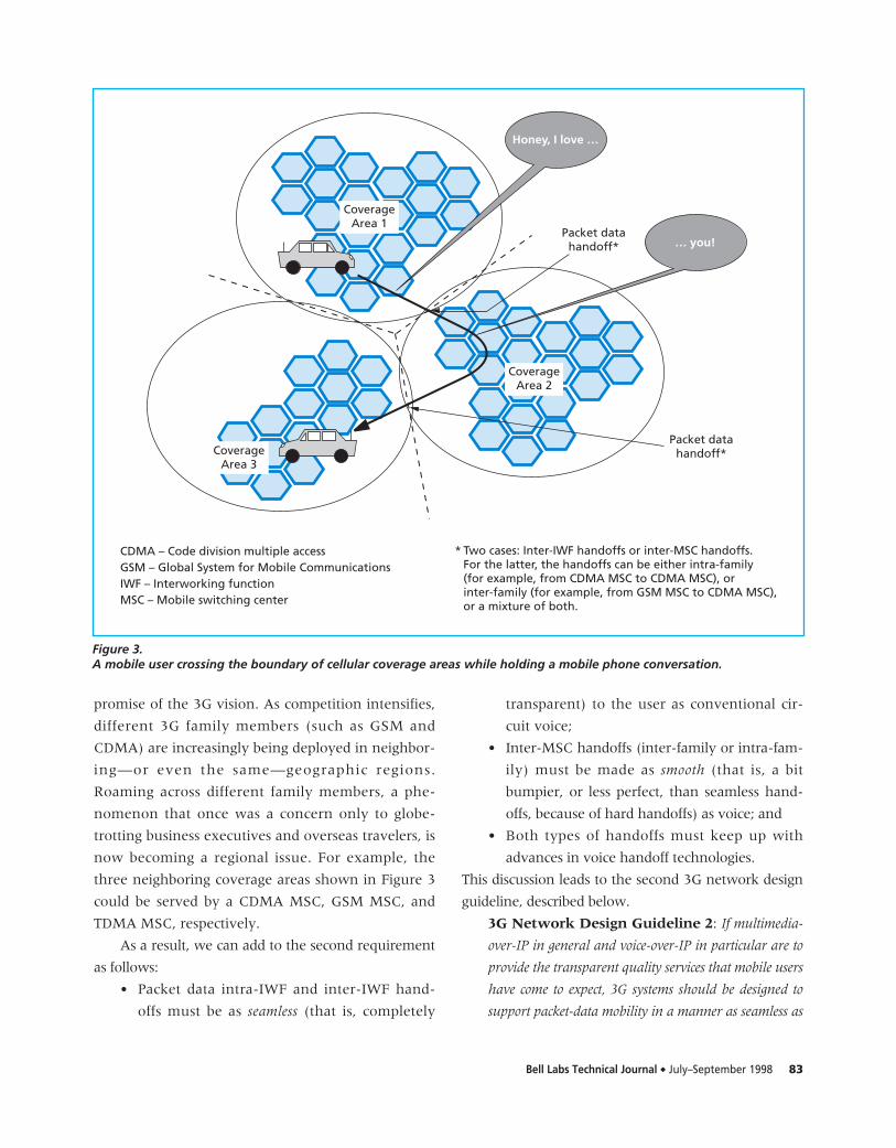
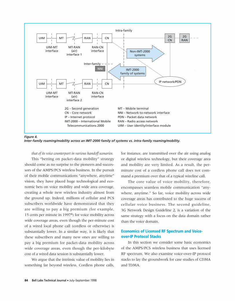
Third-generation mobile terminals capable of
inter-family roaming and even handoffs will typically
support multiple radio interfaces, shown in Figure 4
as the mobile terminal (MT)-RAN air interfaces. A
common 3G NNI, which is being defined by the
IMT-2000 and the ITU, will allow roaming and mobil-
ity across the boundary of the IMT-2000 family of sys-
tems. Such a common NNI is vital to realize the
CN – Core networkGW – GatewayMT – Mobile terminal
PSTN – Public switched telephone networkRAN – Radio access networkUIM – User identity/interface module
Model 1Packet-mode
voicePacket data
(wireless network) Packetdata
Model 2Circuit-mode
voiceCircuit voice
(wireless network)Packetdata
UIM MT RAN CN
Internet
PSTN
H.323GW
H.323GW
Figure 2.Two models of wireless voice-over-IP and their relation to the IMT-2000 network reference model.
Bell Labs Technical Journal ◆ July–September 1998 83
promise of the 3G vision. As competition intensifies,
different 3G family members (such as GSM and
CDMA) are increasingly being deployed in neighbor-
ing—or even the same—geographic regions.
Roaming across different family members, a phe-
nomenon that once was a concern only to globe-
trotting business executives and overseas travelers, is
now becoming a regional issue. For example, the
three neighboring coverage areas shown in Figure 3
could be served by a CDMA MSC, GSM MSC, and
TDMA MSC, respectively.
As a result, we can add to the second requirement
as follows:
• Packet data intra-IWF and inter-IWF hand-
offs must be as seamless (that is, completely
transparent) to the user as conventional cir-
cuit voice;
• Inter-MSC handoffs (inter-family or intra-fam-
ily) must be made as smooth (that is, a bit
bumpier, or less perfect, than seamless hand-
offs, because of hard handoffs) as voice; and
• Both types of handoffs must keep up with
advances in voice handoff technologies.
This discussion leads to the second 3G network design
guideline, described below.
3G Network Design Guideline 2: If multimedia-
over-IP in general and voice-over-IP in particular are to
provide the transparent quality services that mobile users
have come to expect, 3G systems should be designed to
support packet-data mobility in a manner as seamless as
CoverageArea 1
CoverageArea 2
CoverageArea 3
… you!
Honey, I love …
Packet datahandoff*
Packet datahandoff*
* Two cases: Inter-IWF handoffs or inter-MSC handoffs.For the latter, the handoffs can be either intra-family(for example, from CDMA MSC to CDMA MSC), orinter-family (for example, from GSM MSC to CDMA MSC),or a mixture of both.
CDMA – Code division multiple accessGSM – Global System for Mobile CommunicationsIWF – Interworking functionMSC – Mobile switching center
Figure 3.A mobile user crossing the boundary of cellular coverage areas while holding a mobile phone conversation.
84 Bell Labs Technical Journal ◆ July–September 1998
that of its voice counterpart in various handoff scenarios.
This “betting on packet-data mobility” strategy
should come as no surprise to the pioneers and succes-
sors of the AMPS/PCS wireless business. In the pursuit
of their mobile communications “anywhere, anytime”
vision, they have placed huge technological and eco-
nomic bets on voice mobility and wide area coverage,
creating a whole new wireless industry almost from
the ground up. Indeed, millions of cellular and PCS
subscribers worldwide have demonstrated that they
are willing to pay a big premium (for example,
15 cents per minute in 19974) for voice mobility across
wide coverage areas, even though the per-minute cost
of a wired local phone call (cordless or otherwise) is
substantially lower. In a similar way, it is likely that
these subscribers and many new ones are willing to
pay a big premium for packet-data mobility across
wide coverage areas, even though the per-kilobyte
cost of a wired data session is substantially lower.
We argue that the intrinsic value of mobility lies in
something far beyond wireless. Cordless phone calls,
for instance, are transmitted over the air using analog
or digital wireless technology, but their coverage area
and mobility are very limited. As a result, the per-
minute cost of a cordless phone call does not com-
mand a premium over that of a typical wireline call.
The core value of voice mobility, therefore,
encompasses seamless mobile communication “any-
where, anytime.” So far, voice mobility across wide
coverage areas has contributed to the huge success of
cellular voice business. The second guideline,
3G Network Design Guideline 2, is a variation of the
same strategy with a focus on the data domain rather
than the voice domain.
Economics of Licensed RF Spectrum and Voice-over-IP Protocol Stacks
In this section we consider some basic economics
of the AMPS/PCS wireless business that uses licensed
RF spectrum. We also examine voice-over-IP protocol
stacks to lay the groundwork for case studies of CDMA
and TDMA.
2G – Second generationCN – Core networkIP – Internet protocolIMT-2000 – International Mobile Telecommunications 2000
MT – Mobile terminalNNI – Network-to-network interfacePDN – Packet data networkRAN – Radio access networkUIM – User identity/interface module
UIM MT RAN CN
UIM-MTinterface
MT-RAN(air)
interface 1
RAN-CNinterface
NNI
Inter-family
UIM MT RAN CN
UIM-MTinterface
MT-RAN(air)
interface 2
RAN-CNinterface
Non-IMT-2000systems
IMT-2000family of systems
2GCN
2GRAN
Intra-family
IP network/PDN
Figure 4.Inter-family roaming/mobility across an IMT-2000 family of systems vs. intra-family roaming/mobility.
Bell Labs Technical Journal ◆ July–September 1998 85
RF Bit EconomicsTo provide wide area coverage to their millions of
subscribers, major AMPS/PCS wireless service
providers pay a license fee for the exclusive rights to
use a particular band or bands of RF spectrum. In con-
trast, providers of wireless services using unlicensed RF
spectrum (such as the “industrial, scientific and med-
ical,” or ISM, band) must accommodate each other by
resolving any potential radio interference and conflicts.
Thus, AMPS/PCS wireless operators with licensed RF
bands have a big advantage: each has the sole right to
use its licensed RF spectrum, which typically has wide
area coverage. This privilege, however, incurs a price.
The cost of licensed RF spectrum has been calculated
within Lucent to average about 30% of a wireless
operator’s total operating expenses.
In a sense, the AMPS/PCS wireless operators are
in business to sell RF bits piece by piece to cellular
phone users. One way of selling RF bits piecemeal is
to provide cellular voice over the air, where an aver-
age cellular phone call in the U.S. lasts about 3 to 4
minutes. Another way is by transmitting packet data
over the air as either transmission control protocol
(TCP) or UDP traffic. While the average voice traffic
of a cellular voice call is highly predictable, the aver-
age amount of packet data transmitted over the air
on the basis of a per-data session is much less certain.
In fact, the RF bit economics of circuit voice tends to
use a wholesale model, because each call consumes a
relatively large quantity of RF resources, with some
highly predictable statistics (see the case studies later
in this paper). An added benefit is the economics of
scale, since voice traffic today dominates the wireless
network. Packet data tends to follow a retail model
because the connection time of data sessions can vary
significantly and RF resource usage is uncertain.
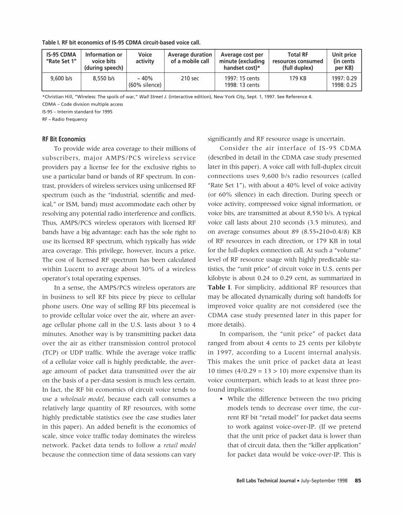
Consider the air interface of IS-95 CDMA
(described in detail in the CDMA case study presented
later in this paper). A voice call with full-duplex circuit
connections uses 9,600 b/s radio resources (called
“Rate Set 1”), with about a 40% level of voice activity
(or 60% silence) in each direction. During speech or
voice activity, compressed voice signal information, or
voice bits, are transmitted at about 8,550 b/s. A typical
voice call lasts about 210 seconds (3.5 minutes), and
on average consumes about 89 (8.55*210*0.4/8) KB
of RF resources in each direction, or 179 KB in total
for the full-duplex connection call. At such a “volume”
level of RF resource usage with highly predictable sta-
tistics, the “unit price” of circuit voice in U.S. cents per
kilobyte is about 0.24 to 0.29 cent, as summarized in
Table I. For simplicity, additional RF resources that
may be allocated dynamically during soft handoffs for
improved voice quality are not considered (see the
CDMA case study presented later in this paper for
more details).
In comparison, the “unit price” of packet data
ranged from about 4 cents to 25 cents per kilobyte
in 1997, according to a Lucent internal analysis.
This makes the unit price of packet data at least
10 times (4/0.29 = 13 > 10) more expensive than its
voice counterpart, which leads to at least three pro-
found implications:
• While the difference between the two pricing
models tends to decrease over time, the cur-
rent RF bit “retail model” for packet data seems
to work against voice-over-IP. (If we pretend
that the unit price of packet data is lower than
that of circuit data, then the “killer application”
for packet data would be voice-over-IP. This is
IS-95 CDMA Information or Voice Average duration Average cost per Total RF Unit price “Rate Set 1” voice bits activity of a mobile call minute (excluding resources consumed (in cents
(during speech) handset cost)* (full duplex) per KB)
9,600 b/s 8,550 b/s ~ 40% 210 sec 1997: 15 cents 179 KB 1997: 0.29(60% silence) 1998: 13 cents 1998: 0.25
Table I. RF bit economics of IS-95 CDMA circuit-based voice call.
*Christian Hill, “Wireless: The spoils of war,” Wall Street J. (interactive edition), New York City, Sept. 1, 1997. See Reference 4.
CDMA – Code division multiple access
IS-95 – Interim standard for 1995
RF – Radio frequency
86 Bell Labs Technical Journal ◆ July–September 1998
unlikely, if not impossible, since packet-mode
voice would consume more RF resources than
its circuit counterpart, as shown in the CDMA
and TDMA case studies presented later in this
paper.) Even if wireless operators were willing
to apply the wholesale pricing model to packet
voice, they would have to distinguish between
the UDP traffic associated with a packet phone
call and other IP traffic.
• Exploiting the pricing difference, providers of
wireless services could potentially get better
returns on their licensed RF spectrum invest-
ment by selling RF bandwidth using packet
data’s retail price, if new and existing packet
data applications could be made compelling
enough and easy enough to use. Until that day
comes, the willingness to pay for higher data
bit rates over the air would remain a question.
• High-speed circuit data applications (such as
wireless video phone) may be more affordable
than their packet data counterparts. For 3G cir-
cuit data services, for instance, the end user
would have to pay 4.5 cents per second at
144 kb/s, 12 cents at 384 kb/s, and 62.5 cents
at 2 Mb/s, according to a simple extrapolation
based on the 1998 unit price shown in Table I.
Assuming the packet data’s unit price is only
five times more expensive than that of circuit
data, the end users would have to pay 21 cents
per second at 144 kb/s, 69 cents at 384 kb/s,
and $3.00 at 2 Mb/s.
For unlicensed RF spectrum, the corresponding RF bit
economics and business models are very different, but
that discussion is beyond the scope of this paper.
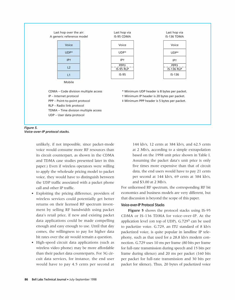
Voice-over-IP Protocol StacksFigure 5 shows the protocol stacks using IS-95
CDMA or IS-136 TDMA for voice-over-IP. At the
application level (on top of UDP), G.7295 can be used
to packetize voice. G.729, an ITU standard of 8 kb/s
packetized voice, is quite popular in landline IP tele-
phony, such as that used for a 28.8 kb/s modem con-
nection. G.729 uses 10 ms per frame (80 bits per frame
for full-rate transmission during speech and 15 bits per
frame during silence) and 20 ms per packet (160 bits
per packet for full-rate transmission and 30 bits per
packet for silence). Thus, 20 bytes of packetized voice
Last hop over the air:A generic reference model
Voice
UDP*
IP†
L2
L1
Mobile
Last hop viaIS-95 CDMA
PPP‡IS-95 RLP
Last hop viaIS-136 TDMA
* Minimum UDP header is 8 bytes per packet.
† Minimum IP header is 20 bytes per packet.
‡ Minimum PPP header is 5 bytes per packet.
CDMA – Code division multiple access
IP – Internet protocol
PPP – Point-to-point protocol
RLP – Radio link protocol
TDMA – Time division multiple access
UDP – User data protocol
IS-95
Voice
UDP*
IP†
PPP‡IS-136 RLP
IS-136
Voice
UDP*
IP†
Figure 5.Voice-over-IP protocol stacks.
Bell Labs Technical Journal ◆ July–September 1998 87
are transmitted every 20 ms during speech. The short
interval of 20 ms helps reduce latency, lessen the
impact of packet loss, and improve voice quality.
For wireless voice-over-IP to be economical, we
must understand and analyze the additional overhead
incurred by the headers of an IS-95 or IS-136 traffic
frame, radio link protocol (RLP), point-to-point proto-
col (PPP), IP, and UDP. Since the header overhead of
UDP, IP, and PPP is well known, as shown in Figure 5,
we will focus on L1 (IS-95 and IS-136) and RLP. The
information on minimum header sizes of UDP, IP, and
PPP is from W. R. Stevens6 and D. E. Comer.7 The
next two sections describe two case studies of voice-
over-IP—one using IS-95 CDMA and the other using
IS-136 TDMA.
Case Study 1: IS-95 CDMAIn this section we present a case study of voice-
over-IP using IS-95 CDMA. For simplicity, we ignore
many of the important and practical issues like hand-
offs, power control, and synchronization.
Voice signals in IS-95 CDMA are digitized to pro-
duce voice traffic frames, and each frame is transmit-
ted across the air interface at 20 ms intervals. This
short interval produces a voice quality comparable to
that of wireline. CDMA maximizes the efficiency of RF
resource usage by employing digital compression tech-
nology and exploiting some well-known voice activity
patterns during voice conversations. In digital com-
pression, for example, only about an 8 kb/s transmis-
sion rate over the air is needed to achieve voice quality
equivalent to landlines, where 64 kb/s voice encoding
is typically used. While full-duplex connections are
necessary for a good experience in two-way conversa-
tion, most of the time only one end speaks and the
other end listens. CDMA takes advantage of this (as
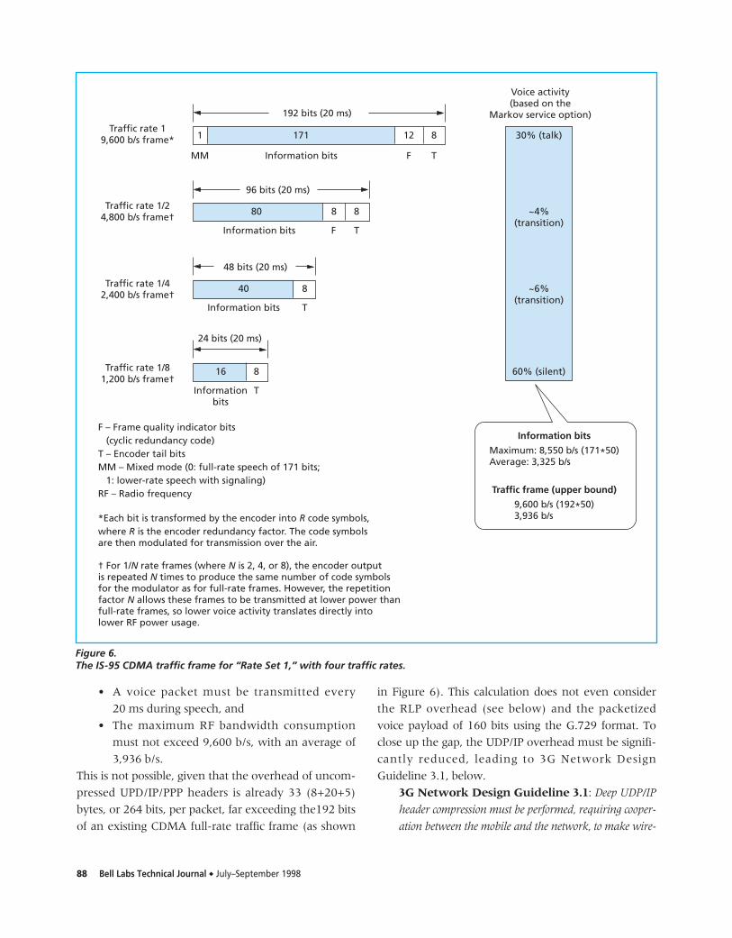
shown in Figure 6) by dynamically switching from
the so-called full-rate frame (9,600 b/s) during speech to
a 1/8 rate frame during silence (1,200 b/s), which fur-
ther improves the usage efficiency of RF power. As a
result, the average traffic frame is only 3,936 b/s every
20 ms, even though the maximum is 9,600 b/s.
Similarly, the average RF resource usage is 3,325 b/s
every 20 ms for information or voice bits, even
though the maximum is 8,550 b/s, as shown in
Figure 6. Four traffic rates are used at different levels
of voice activity; their statistics, based on the Markov
service option, may vary slightly from actual field data.
The RF power resources consumed by 1/8 rate
frames during the 60% silence, or about 18% of the
total RF power resources consumed by an average
circuit-mode voice call (assuming that frame trans-
mit power is proportional to frame rate), are not
completely “wasted.” In fact, packet-mode voice
may not be able to provide advantages of RF power
resource efficiency compared to circuit-mode voice
for three reasons.
First, the 1/8 rate frames are needed to support
traffic channel supervision when voice and signaling
are carried over the same radio channel. The supervi-
sion procedures detect any loss of the signaling chan-
nel and remove calls with degraded RF conditions
from the system. For instance, if a base station were
allowed to turn off its transmitter during low voice
activity, the mobile unit would react in a similar man-
ner by turning off its transmitter. This would degrade
reverse voice quality and reverse signaling reliability,
and would probably contribute to both forward and
reverse power control overshoots when voice activity
resumed. As such, even packet-mode voice would
probably be required to use 1/8 rate frames during
silence to keep the traffic channel alive.
Second, it is possible for 3G systems to carry pack-
etized voice and signaling on separate radio channels.
This scheme could enable a base station to selectively
transmit nothing on a voice channel during silence,
while maintaining traffic channel supervision and
power control over a separate signaling channel. The
new dedicated signaling channel, however, would still
consume RF power resources during silent periods.
Third, if traffic channel supervision were somehow
changed to allow a 3G system in a base station to turn
off its voice/signaling channel during silence without
experiencing the adverse effects described above, any
advantages that might benefit packet-mode voice could
also benefit circuit-mode voice through new circuit
voice options defined to fully exploit this change.
To compete with circuit voice on both quality and
price, any last-hop voice-over-IP scheme using CDMA
must meet the following two challenges:
88 Bell Labs Technical Journal ◆ July–September 1998
• A voice packet must be transmitted every
20 ms during speech, and
• The maximum RF bandwidth consumption
must not exceed 9,600 b/s, with an average of
3,936 b/s.
This is not possible, given that the overhead of uncom-
pressed UPD/IP/PPP headers is already 33 (8+20+5)
bytes, or 264 bits, per packet, far exceeding the192 bits
of an existing CDMA full-rate traffic frame (as shown
in Figure 6). This calculation does not even consider
the RLP overhead (see below) and the packetized
voice payload of 160 bits using the G.729 format. To
close up the gap, the UDP/IP overhead must be signifi-
cantly reduced, leading to 3G Network Design
Guideline 3.1, below.
3G Network Design Guideline 3.1: Deep UDP/IP
header compression must be performed, requiring cooper-
ation between the mobile and the network, to make wire-
1 171 12 8
192 bits (20 ms)
MM Information bits F T
96 bits (20 ms)
80 8 8
Information bits F T
48 bits (20 ms)
40 8
Information bits T
24 bits (20 ms)
16 8
Informationbits
T
Traffic rate 19,600 b/s frame*
Traffic rate 1/24,800 b/s frame†
Traffic rate 1/42,400 b/s frame†
Traffic rate 1/81,200 b/s frame†
F – Frame quality indicator bits (cyclic redundancy code)T – Encoder tail bitsMM – Mixed mode (0: full-rate speech of 171 bits; 1: lower-rate speech with signaling)RF – Radio frequency
*Each bit is transformed by the encoder into R code symbols,where R is the encoder redundancy factor. The code symbolsare then modulated for transmission over the air.
† For 1/N rate frames (where N is 2, 4, or 8), the encoder outputis repeated N times to produce the same number of code symbolsfor the modulator as for full-rate frames. However, the repetitionfactor N allows these frames to be transmitted at lower power thanfull-rate frames, so lower voice activity translates directly intolower RF power usage.
Voice activity(based on the
Markov service option)
30% (talk)
~4%(transition)
~6%(transition)
60% (silent)
Information bits
Maximum: 8,550 b/s (171*50)Average: 3,325 b/s
Traffic frame (upper bound)
9,600 b/s (192*50)3,936 b/s
Figure 6.The IS-95 CDMA traffic frame for “Rate Set 1,” with four traffic rates.
Bell Labs Technical Journal ◆ July–September 1998 89
less voice-over-IP and multimedia-over-IP economical.
While the compression task can be performed by
any of the levels lower than the IP layer, PPP (that is,
L2) seems to be the most appropriate candidate from
a protocol layering perspective, as explained below.
(An alternative is to perform the compression one
layer below the PPP layer. In the context of
3G packet data, this is the link access control [LAC]
layer [in the process of being defined in the
IMT-2000/ITU standards], which sits between the
PPP layer and the RLP layer. This alternative is dis-
cussed at the end of this section.)
PPP is the layer where Van Jacobson TCP/IP
header compression,8 which reduces the number of
TCP/IP header bytes from 40 to 5, is typically imple-
mented. For wireless IP telephony, PPP could compress
the UDP/IP headers in a similar fashion, assuming that
the call control and call processing protocols used by
the application could be monitored and understood by
PPP. (One such call control and call processing protocol
is the H.323 family of standards,3 including the
H.245 control and Q.931 call signaling protocols.) This
is analogous to the case of TCP/IP header compression,
where the connection setup messages and states are
interpreted by PPP. The header of each encoded voice
packet can be deeply compressed by PPP before being
transmitted over the wireless link; it can then be
decompressed by the receiving PPP, assuming each end
point knows which calls are in progress and has been
appropriately modified to understand the semantics of
the particular voice-over-IP application being used.
(The voice packet includes UDP/IP headers, which are
28 bytes long, and any other headers added by the
application. For example, H.323 dictates the use of real-
time protocol [RTP],9 which adds a time-stamp,
sequence number, and other identifiers to each packet.
It may in fact be extremely difficult to recover time-
stamp and sequence number information, owing to
loss of frames at the RLP layer. This loss occurs because
the RLP layer will probably be running in the “trans-
parent” mode, meaning the RLP will not perform any
retransmissions.)
In the remainder of this paper we will make the
very optimistic assumption that all such overhead can
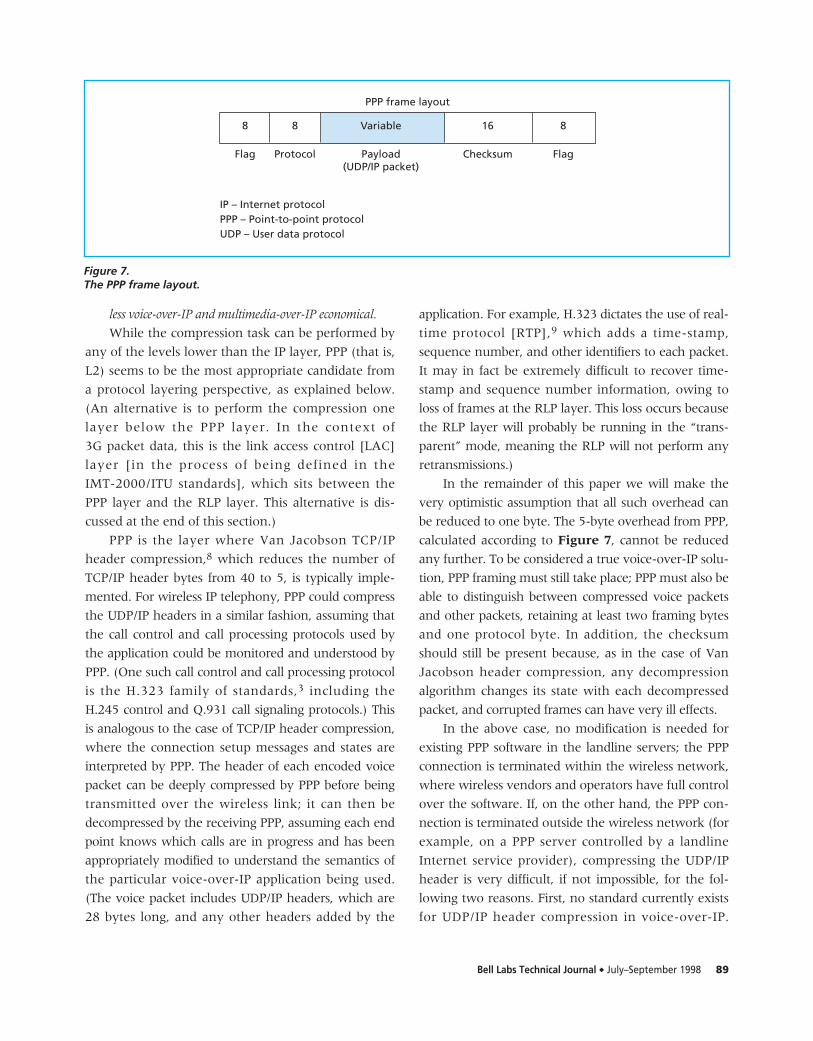
be reduced to one byte. The 5-byte overhead from PPP,
calculated according to Figure 7, cannot be reduced
any further. To be considered a true voice-over-IP solu-
tion, PPP framing must still take place; PPP must also be
able to distinguish between compressed voice packets
and other packets, retaining at least two framing bytes
and one protocol byte. In addition, the checksum
should still be present because, as in the case of Van
Jacobson header compression, any decompression
algorithm changes its state with each decompressed
packet, and corrupted frames can have very ill effects.
In the above case, no modification is needed for
existing PPP software in the landline servers; the PPP
connection is terminated within the wireless network,
where wireless vendors and operators have full control
over the software. If, on the other hand, the PPP con-
nection is terminated outside the wireless network (for
example, on a PPP server controlled by a landline
Internet service provider), compressing the UDP/IP
header is very difficult, if not impossible, for the fol-
lowing two reasons. First, no standard currently exists
for UDP/IP header compression in voice-over-IP.
PPP frame layout
8 8 Variable 16 8
Flag Protocol Payload(UDP/IP packet)
Checksum Flag
IP – Internet protocolPPP – Point-to-point protocolUDP – User data protocol
Figure 7.The PPP frame layout.
90 Bell Labs Technical Journal ◆ July–September 1998
Second, even if one does emerge in the future, it is
unlikely that such a standard would take into full
account the complexity of wireless communications
over the air and be widely deployed in the vast num-
ber of landline PPP servers. Therefore:
3G Network Design Guideline 3.2: The UDP/IP
header compression should be performed within the
wireless network to make it completely transparent to
external networks. In other words, the PPP connection
originated from the mobile device should be terminated
within the wireless network to minimize changes in the
existing landline (layer 2) software.
Indeed, this is an area where cellular equipment
vendors, cellular service providers, and mobile device
manufacturers alike could differentiate themselves by
adding unique wireless value, such as intelligent
UDP/IP header compression for efficient voice-over-IP
and multimedia-over-IP.
Taken together, 3G Network Design
Guidelines 3.1 and 3.2 indicate that early PPP termina-
tion within the wireless network improves UDP/IP
header compression, making it the most logical choice
to support wireless voice-over-IP and multimedia-
over-IP in an efficient manner. However, forcing PPP
termination within the wireless network may block
end users from some important packet data services
that rely on end-to-end PPP connection.
There are at least three ways to address this issue.
The first approach is to support “dual stacks” in the
wireless network, depending on the service requested
by the user. The wireless network is equipped with the
hardware and software needed to support both early
PPP termination and PPP as a service. This, of course,
tends to increase the total cost. A second approach is
to augment the mobile voice network with an inde-
pendent data network, where each network is opti-
mized for its prime services. However, 3G multimedia
still needs to be supported by either:
• The data network, again calling for early PPP
termination for header compression, or
• The voice network, calling for support of
something like broadband ISDN (B-ISDN),
which is discussed in more detail in the last
two sections of this paper.
The third approach is to offer PPP services via
PPP-over-IP, applying once again the metaphor of
voice-over-IP and multimedia-over-IP. One example is
the so-called voluntary tunneling,10 which establishes a
static end-to-end tunnel over the IP between the end
user and a remote PPP server. Any UDP/IP header
compression performed by the wireless network and
mobile unit will benefit voice-over-IP, multimedia-
over-IP, and PPP-over-IP.
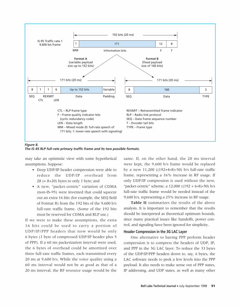
The IS-95 RLP Traffic FrameThis section analyzes the RLP, which sits on top of
IS-95. Figure 8 depicts the IS-95 RLP full-rate traffic
frame11 and two of its formats, A and B. The latter
supports the so-called transparent mode. In this mode
the layer above RLP will be responsible for retransmis-
sion if a transmission error occurs over the air. Each
format is 171 bits in length which, as a payload, fits
into the IS-95 CDMA “Rate Set 1” traffic frame shown
in Figure 6. During speech (40% of the time),
Format B—whose fixed payload is 160 bits—can be
used to carry the voice-over-IP information. However,
packetized voice using G.729 is 160 bits every 20 ms,
and the overhead of uncompressed UPD/IP/PPP/RLP is
275 (33*8+8+3) bits, making it impossible to squeeze
the 435 (160+275) bits into the 160 data bits of
Format B without using more RF resources.
If a voice-over-IP designer were allowed to allo-
cate more RF resources and still keep the 20 ms per
packet requirement, then the 9,600 b/s full-rate
traffic frame would be replaced by a new
22,800 ( (192+33*8)*50) b/s full-rate traffic frame, at
least doubling the RF resource usage when compared
with the circuit voice counterpart. This 22,800 b/s full-
rate traffic frame is purely hypothetical; no such frame
exists in current IS-95 CDMA standards. In other
words, CDMA voice-over-IP for licensed cellular/PCS
radio spectrum is either uneconomical at 20 ms per
packet, or the use of longer packetization intervals will
result in poor voice quality because of increased
latency and the impact of packet loss. However, the
situation could be improved significantly by combining
some deep UPD/IP header compression and other
techniques, as we discuss below.
An Analysis with Optimistic AssumptionsTo assess the theoretical bounds and thus the ulti-
mate possibilities for voice-over-IP using CDMA, we
Bell Labs Technical Journal ◆ July–September 1998 91
may take an optimistic view with some hypothetical
assumptions. Suppose:
• Deep UDP/IP header compression were able to
reduce the UDP/IP overhead from
28 (= 8+20) bytes to only 1 byte; and
• A new, “packet-centric” variation of CDMA
(non-IS-95) were invented that could squeeze
out an extra 16 bits (for example, the SEQ field
of Format B) from the 192 bits of the 9,600 b/s
full-rate traffic frame. (Some of the 192 bits
must be reserved for CDMA and RLP use.)
If we were to make these assumptions, the extra
16 bits could be used to carry a portion of
UDP/IP/PPP headers that now would be only
6 bytes (1 byte of compressed UDP/IP header plus 5
of PPP). If a 60 ms packetization interval were used,
the 6 bytes of overhead could be amortized over
three full-rate traffic frames, each transmitted every
20 ms at 9,600 b/s. While the voice quality using a
60 ms interval would not be as good as that of a
20 ms interval, the RF resource usage would be the
same. If, on the other hand, the 20 ms interval
were kept, the 9,600 b/s frame would be replaced
by a new 11,200 ((192+4*8)*50) b/s full-rate traffic
frame, representing a 16% increase in RF usage. If
only UDP/IP compression is used without the new,
“packet-centric” scheme, a 12,000 ((192 + 6*8)*50) b/s
full-rate traffic frame would be needed instead of the
9,600 b/s, representing a 25% increase in RF usage.
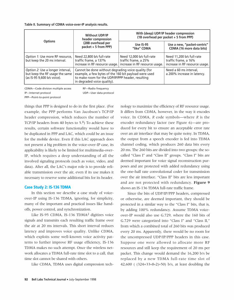
Table II summarizes the results of the above
analysis. It is important to remember that the results
should be interpreted as theoretical optimum bounds,
since many practical issues like handoffs, power con-
trol, and signaling have been ignored for simplicity.
Header Compression in the 3G LAC LayerOne alternative to having PPP perform header
compression is to compress the headers of UDP, IP,
and PPP in the 3G LAC layer. To reduce the 33 bytes
of the UDP/IP/PPP headers down to, say, 6 bytes, the
LAC software needs to peek a few levels into the PPP
payload. It also needs to make sense out of PPP states,
IP addressing, and UDP states, as well as many other
CTL – RLP frame typeF – Frame quality indicator bits (cyclic redundancy code)LEN – Data lengthMM – Mixed mode (0: full-rate speech of 171 bits; 1: lower-rate speech with signaling)
REXMIT – Retransmitted frame indicatorRLP – Radio link protocolSEQ – Data frame sequence numberT – Encoder tail bitsTYPE – Frame type
1 171 12 8
MM Information bits F T
192 bits (20 ms)
IS-95 Traffic rate 19,600 b/s frame
Format A(variable payload
size up to 152 bits)
8
SEQ
171 bits (20 ms)
1 1 6 Up to 152 bits Variable
REXMITCTL LEN
Data Padding
Format B(fixed payload
size of 160 bits)
8
SEQ
171 bits (20 ms)
160 3
Data TYPE
Figure 8.The IS-95 RLP full-rate primary traffic frame and its two possible formats.
92 Bell Labs Technical Journal ◆ July–September 1998
things that PPP is designed to do in the first place. (For
example, the PPP performs Van Jacobson’s TCP/IP
header compression, which reduces the number of
TCP/IP headers from 40 bytes to 5.8) To achieve these
results, certain software functionality would have to
be duplicated in PPP and LAC, which could be an issue
for the mobile device. Even if this LAC approach does
not present a big problem in the voice-over-IP case, its
applicability is likely to be limited for multimedia-over-
IP, which requires a deep understanding of all the
involved signaling protocols (such as voice, video, and
data). After all, the LAC’s major role is to provide reli-
able transmission over the air, even if its use makes it
necessary to reserve some additional bits for its header.
Case Study 2: IS-136 TDMAIn this section we describe a case study of voice-
over-IP using IS-136 TDMA, ignoring, for simplicity,
many of the important and practical issues like hand-
offs, power control, and synchronization.
Like IS-95 CDMA, IS-136 TDMA2 digitizes voice
signals and transmits each resulting traffic frame over
the air at 20 ms intervals. This short interval reduces
latency and improves voice quality. Unlike CDMA,
which exploits some well-known voice activity pat-
terns to further improve RF usage efficiency, IS-136
TDMA makes no such attempt. Once the wireless net-
work allocates a TDMA full-rate time slot to a call, that
time slot cannot be shared with others.
Like CDMA, TDMA uses digital compression tech-
nology to maximize the efficiency of RF resource usage.
It differs from CDMA, however, in the way it encodes
voice. In CDMA, R code symbols—where R is the
encoder redundancy factor (see Figure 6)—are pro-
duced for every bit to ensure an acceptable error rate
over an air interface that may be quite noisy. In TDMA,
the output from a speech encoder is fed into TDMA
channel coding, which produces 260 data bits every
20 ms. The 260 bits are divided into two groups: the so-
called “Class I” and “Class II” groups. “Class I” bits are
deemed important for voice signal reconstruction pur-
poses and are protected with added redundancy using
the one-half rate convolutional coder for transmission
over the air interface. “Class II” bits are less important
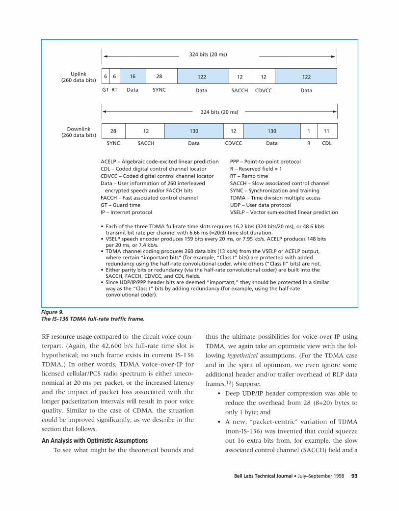
and are not protected with redundancy. Figure 9
shows an IS-136 TDMA full-rate traffic frame.
Since the bits of UDP/IP/PPP headers, compressed
or otherwise, are deemed important, they should be
protected in a similar way to the “Class I” bits, that is,
by adding 100% redundancy. Assume TDMA voice-
over-IP would also use G.729, where the 160 bits of
G.729 were categorized into “Class I” and “Class II,”
from which a combined total of 260 bits was produced
every 20 ms. Apparently, there would be no room for
the uncompressed UDP/IP/PPP headers in this case.
Suppose one were allowed to allocate more RF
resources and still keep the requirement of 20 ms per
packet. This change would demand the 16,200 b/s be
replaced by a new TDMA full-rate time slot of
42,600 ( (324+33*8*2)*50) b/s, at least doubling the
Option 1: Use more RF resource, Need 22,800 b/s full-rate Need 12,000 b/s full-rate Need 11,200 b/s full-rate but keep the 20 ms interval. traffic frame, a 137% traffic frame, a 25% traffic frame, a 16%
increase in RF resource usage. increase in RF resource usage. increase in RF resource usage.
Option 2: Use a longer interval, Cannot be done without degrading voice quality (for Need a 60 ms interval,but keep the RF usage the same example, a few bytes of the 160 bit payload were used a 200% increase in latency.(as IS-95 9,600 b/s voice). to make room for the UDP/IP/PPP header, resulting
in degraded voice quality).
Table II. Summary of CDMA voice-over-IP analysis results.
CDMA—Code division multiple access RF—Radio frequency
IP—Internet protocol UDP—User data protocol
PPP—Point-to-point protocol
Without UDP/IPheader compression(28B overhead per
packet + 5 from PPP)
OptionsUse IS-95
“like” CDMAUse a new, “packet-centric”CDMA (16 more data bits)
With (deep) UDP/IP header compression(1B overhead per packet + 5 from PPP)
Bell Labs Technical Journal ◆ July–September 1998 93
RF resource usage compared to the circuit voice coun-
terpart. (Again, the 42,600 b/s full-rate time slot is
hypothetical; no such frame exists in current IS-136
TDMA.) In other words, TDMA voice-over-IP for
licensed cellular/PCS radio spectrum is either uneco-
nomical at 20 ms per packet, or the increased latency
and the impact of packet loss associated with the
longer packetization intervals will result in poor voice
quality. Similar to the case of CDMA, the situation
could be improved significantly, as we describe in the
section that follows.
An Analysis with Optimistic AssumptionsTo see what might be the theoretical bounds and
thus the ultimate possibilities for voice-over-IP using
TDMA, we again take an optimistic view with the fol-
lowing hypothetical assumptions. (For the TDMA case
and in the spirit of optimism, we even ignore some
additional header and/or trailer overhead of RLP data
frames.12) Suppose:
• Deep UDP/IP header compression was able to
reduce the overhead from 28 (8+20) bytes to
only 1 byte; and
• A new, “packet-centric” variation of TDMA
(non-IS-136) was invented that could squeeze
out 16 extra bits from, for example, the slow
associated control channel (SACCH) field and a
6 122 122
GT Data Data
324 bits (20 ms)
12
CDVCC
12
SACCH
6
RT
16
Data
28
SYNC
Uplink(260 data bits)
28
SYNC
324 bits (20 ms)
Downlink(260 data bits)
12
SACCH
130
Data
12
CDVCC
130
Data
1
R
11
CDL
ACELP – Algebraic code-excited linear predictionCDL – Coded digital control channel locatorCDVCC – Coded digital control channel locatorData – User information of 260 interleaved encrypted speech and/or FACCH bitsFACCH – Fast associated control channelGT – Guard timeIP – Internet protocol
• Each of the three TDMA full-rate time slots requires 16.2 kb/s (324 bits/20 ms), or 48.6 kb/stransmit bit rate per channel with 6.66 ms (=20/3) time slot duration.
• VSELP speech encoder produces 159 bits every 20 ms, or 7.95 kb/s. ACELP produces 148 bitsper 20 ms, or 7.4 kb/s.
• TDMA channel coding produces 260 data bits (13 kb/s) from the VSELP or ACELP output,where certain “important bits” (for example, “Class I” bits) are protected with addedredundancy using the half-rate convolutional coder, while others (”Class II” bits) are not.
• Either parity bits or redundancy (via the half-rate convolutional coder) are built into theSACCH, FACCH, CDVCC, and CDL fields.
• Since UDP/IP/PPP header bits are deemed “important,” they should be protected in a similarway as the “Class I” bits by adding redundancy (for example, using the half-rateconvolutional coder).
PPP – Point-to-point protocolR – Reserved field = 1RT – Ramp timeSACCH – Slow associated control channelSYNC – Synchronization and trainingTDMA – Time division multiple accessUDP – User data protocolVSELP – Vector sum-excited linear prediction
Figure 9.The IS-136 TDMA full-rate traffic frame.
94 Bell Labs Technical Journal ◆ July–September 1998
portion of the synchronization and training
(SYNC) field (thus the total data bits would be
260+16=276).
If we were to make these assumptions, the 16
extra bits could be used to carry a portion of
UDP/IP/PPP headers that now would be only 6 bytes
(1 byte of compressed UDP/IP header plus 5 bytes of
PPP). Because the header bits are considered impor-
tant, they should be treated as “Class I” bits with
added redundancy protection for more reliable
transmission over the air. If a 120 ms packetization
interval were to be used, the 6 bytes of compressed
UDP/IP/PPP header overhead could be amortized
over six traffic frames, each transmitted every 20 ms
at 16,200 b/s per full-rate time slot. While the voice
quality using a 120 ms interval will not be as good as
that of a 20 ms interval, the RF resource usage is
kept the same. If, on the other hand, the 20 ms
interval were kept, the 16,200 b/s time slot would be
replaced by a new TDMA full-rate time slot of
19,400 ( (324+4*8*2)*50) b/s, representing a 19.8%
increase in RF usage. If only UDP/IP compression were
used, without the new, “packet-centric” scheme, the
9,600 b/s time slot would be replaced by a full-rate
time slot of 21,000 ( (324+6*8*2)*50) b/s, represent-
ing a 29.6% increase in RF usage.
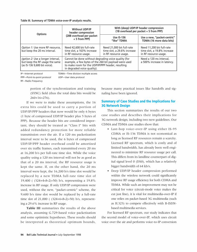
Table III summarizes the results of the above
analysis, assuming G.729-based voice packetization
and some optimistic hypotheses. These results should
be interpreted as theoretical optimum bounds,
because many practical issues like handoffs and sig-
naling have been ignored.
Summary of Case Studies and the Implications for3G Network Design
This section summarizes the results of our two
case studies and describes their implications for
3G network design, including two new guidelines. Our
CDMA and TDMA case studies show that:
• Last-hop voice-over-IP using either IS-95
CDMA or IS-136 TDMA is not economical as
long as licensed RF resources remain a scarcity.
Licensed RF spectrum, which is costly and of
limited bandwidth, has already been well engi-
neered to minimize RF resource usage per call.
This differs from its landline counterpart of dig-
ital signal level 0 (DS0), which has a relatively
bigger bandwidth of 64 kb/s.
• Deep UDP/IP header compression performed
within the wireless network could significantly
improve RF usage efficiency for both CDMA and
TDMA. While such an improvement may not be
critical for voice (circuit-mode voice makes the
cut just fine), it is vital for multimedia-over-IP if
one relies on packet-based 3G multimedia (such
as H.323) to compete effectively with B-ISDN-
based multimedia services.
For licensed RF spectrum, our study indicates that
the second model of voice-over-IP, which uses circuit
voice over the air and performs voice-to-IP conversion
Option 1: Use more RF resource, Need 42,600 b/s full-rate Need 21,000 b/s full-rate Need 11,200 b/s full-rate but keep the 20 ms interval. time slot, a 163% increase time slot, a 29.6% increase time slot, a 19.8% increase
in RF resource usage. in RF resource usage. in RF resource usage.
Option 2: Use a longer interval, Cannot be done without degrading voice quality (for Need a 120 ms interval,but keep the RF usage the same example, a few bytes of the 260 bit payload were used a 500% increase in latency.(as IS-136 9,600 b/s voice). to make room for the UDP/IP/PPP header, resulting
in degraded voice quality).
Options
Table III. Summary of TDMA voice-over-IP analysis results.
IP—Internet protocol TDMA—Time division multiple access
PPP—Point-to-point protocol UDP—User data protocol
RF—Radio frequency
Without UDP/IPheader compression
(28B overhead per packet+ 5 from PPP) Use IS-136
“like” TDMAUse a new, “packet-centric”TDMA (16 more data bits)
With (deep) UDP/IP header compression(1B overhead per packet + 5 from PPP)
Bell Labs Technical Journal ◆ July–September 1998 95
in the wireless network (see Figure 2), would be more
practical than the first model. The second model com-
bines the best of two worlds: the well-engineered air
interface of IS-95 CDMA or IS-136 TDMA, and the
efficiency and cost effectiveness of wired IP networks.
This analysis leads to:
3G Network Design Guideline 4: 3G networks
should be designed to efficiently support the second model
of voice-over-IP, which uses circuit voice over the air and
performs voice-to-IP conversion (and vice versa) within
the wireless network (see Figure 2).
The next design guideline focuses on wireless
multimedia, an important service required for
3G/IMT-2000 systems. There are at least two ways to
provide 3G wireless multimedia services. One alter-
native is to build native B-ISDN capabilities into the
wireless network. For certain applications like wire-
less videophone and video on demand, the circuit-
based technology tends to use RF resources
efficiently while providing good quality of service.
However, the associated costs of development and
deployment could be very high. Migrating the huge
embedded base to B-ISDN while maintaining voice
feature parity also presents a serious challenge, both
technically and financially.
Another alternative is to rely on applications soft-
ware such as H.323, which is essentially wireless mul-
timedia-over-IP. This approach costs less because,
unlike B-ISDN, it does not require revolutionary
changes in the embedded base. For packet-based mul-
timedia-over-IP to compete with B-ISDN multimedia,
however, it is critical that deep UDP/IP header com-
pression, as discussed in CDMA and TDMA case stud-
ies, be performed within the wireless network to
improve the efficiency of RF resource usage. Similar to
the case of voice-over-IP, the layer that seems to be
most appropriate to carry out this task is Layer 2, or
the PPP layer. Cooperation between the mobile device
and the wireless network can make PPP modifications
transparent to the external networks, as described in
the guideline below:
3G Network Design Guideline 5: For packet-
based multimedia (that is, multimedia-over-IP) to com-
pete effectively with B-ISDN-based multimedia services,
deep UDP/IP compression must be performed within the
wireless network and must be made completely trans-
parent to the external networks.
ConclusionsAs the next-generation wireless infrastructure,
3G systems provide high-speed data bit rates over the
air and advanced services such as multimedia, Internet
access, and seamless roaming and mobility across the
IMT-2000 family of systems. While 3G, or next gener-
ation, systems will offer sufficient advantages over 2G,
or current generation, systems, the huge embedded
base of 2G systems—worth about US$40-$50 billion,
according to Lucent calculations—makes it an eco-
nomic necessity to take an evolutionary path to 3G.
Evolution, rather than revolution, from 2G to 3G
means that IMT-2000 multimedia services may be
provided more cost effectively by packet-based multi-
media or wireless multimedia-over-IP (such as H.323),
as opposed to the more expensive B-ISDN revolution-
ary approach. Our study of voice-over-IP using IS-95
CDMA and IS-136 TDMA showed that deep UDP/IP
header compression within the wireless network is a
must for multimedia-over-IP to compete effectively
with B-ISDN-based multimedia. The investment in
header compression will benefit not only multimedia-
over-IP, but also voice-over-IP and PPP-over-IP. The
compression should be carried out in Layer 2 (that is,
the PPP layer), in a manner completely transparent to
the external networks.
While such compression will also help packet-
mode voice, wireless voice-over-IP in general may not
be economical for licensed cellular/PCS radio spectrum
because the cost of licensing the RF spectrum is high
and the circuit-mode air interface is already efficient. A
more practical approach is to use circuit voice over the
air and perform voice-to-IP conversion in the wireless
network. This combines the best of two worlds: the
well-engineered air interface of IS-95 CDMA or IS-136
TDMA, and the efficiency and cost effectiveness of
wired IP networks.
The rise of the AMPS/PCS wireless business as a
new global industry may be traced back, in a sense, to
its root, where the pioneers and their successors put
tremendous focus on voice mobility across wide cover-
age areas. As wireless voice and data converge in the
96 Bell Labs Technical Journal ◆ July–September 1998
3G world, betting on packet-data mobility in addition
to voice mobility may be a key element for the wire-
less industry in fueling the explosive growth of mobile
subscribers worldwide.
AcknowledgmentsThis work is part of a collaboration between a
wireless development organization and a Bell Labs
research department. The authors are grateful to David
Weiss, of the Software Production Research
Department, and Bill Skeens, Dennis Hanson, Bob
Sellinger, Jay Hemmady, and Wayne Strom, all from
the Wireless Networks Group, for starting and contin-
uously supporting the collaboration. Special apprecia-
tion goes to Edward Berliner and Lynell Cannell, also
of the Wireless Networks Group, for their consultation
and comments on CDMA and TDMA areas, and to
H. F. Braunlich and W. C. Wiberg for the information
they provided. The authors also thank the anonymous
reviewers for their useful suggestions and Michael
Benedikt, Glenn Bruns, and Ian Sutherland, members
of Bell Labs Research, and Lucia Sellers, of the
Wireless Networks Group, for their support and
review of early drafts of the manuscript.
References1. Mobile Station–Base Station Compatibility Standard
for Dual-Mode Wideband Spread Spectrum CellularSystem, IS-95B, Ballot Version, Telecommuni-cations Industry Association, Washington, D.C.,Mar. 1998.
2. EIA/TIA Interim Standard IS-136-A, Telecommuni-cations Industry Association, Washington, D.C.,Dec. 1997.
3. A premier on the H.323 series standard,http://www.databeam.com
4. Christian Hill, “Wireless: The spoils of war,”Wall Street J. (interactive edition), New YorkCity, Sept. 1, 1997.http://update2.wsj.com/public/current/articles/SB873665261584758000.htm
5. Coding of speech at 8 kbit/s using conjugate-structurealgebraic-code-excited linear-prediction (CS-ACELP),http://www.itu.int/itudoc/itu-t/rec/g/g700-799/g729_32350.html
6. W. Richard Stevens, TCP/IP Illustrated, Vol. 1: TheProtocols, Addison-Wesley, Reading, Mass., 1994.
7. Douglas E. Comer, Interworking with TCP/IP, Vol. I: Principles, Protocols, and Architecture,Prentice-Hall, Englewood Cliffs, N. J., 1991.
8. Van Jacobson, Compressing TCP/IP headers for
low-speed serial links, RFC 1144, Feb. 1990.http://nic.mil/ftp/rfc/rfc1144.txt
9. H. Schulzrinne, S. Casner, R. Frederick, and V. Jacobson, A transport protocol for real-timeapplications, Audio-Video Transport WorkingGroup, RFC 1889, Jan. 1996.http://nic.mil/ftp/rfc/rfc1189.txt
10. http://www.nts.com/NTS/tunel.htmlhttp://www.microsoft.com/communications/rasopfaq.htmhttp://www.microsoft.com/communications/rasfeatures.htm
11. Data service options for wideband spread spectrumsystem: Radio link protocol, PN-3676.2(TIA/EIA/IS-707.2), TelecommunicationsIndustry Association, Washington, D.C.,Nov. 19, 1997.
12. TDMA wireless system radio interface: Radio linkprotocol 1, PN-3795, TR-45, TelecommunicationsIndustry Association, Washington, D.C., Jan. 1997.
(Manuscript approved August 1998)
JIN WANG is a member of technical staff in theWireless Architecture and PerformanceDepartment at Lucent’s Wireless NetworksGroup in Naperville, Illinois. After receivingB.S. and M.S. degrees in computer sciencefrom Qinghua University in Beijing, China,
he earned a Ph.D. in computer science and engineeringfrom Wright State University in Dayton, Ohio.Dr. Wang is working on FLEXENT™ MSC architectureand 3G/IMT-2000 related issues. His recent interestsinclude mobility, call processing, wireless data, andinterworking and interoperability.
PETER J. McCANN received a B.S. in engineering andapplied science from the California Instituteof Technology in Pasadena, and M.S. andD.Sc. degrees in computer science fromWashington University in St. Louis, Missouri.A member of technical staff in the Software
Production Research Department of Bell Labs inNaperville, Illinois, Dr. McCann is working on models andtechniques for designing mobile computing systems.
PATVARDHANA B. GORREPATI is a distinguished mem-ber of technical staff in the WirelessArchitecture and Performance Departmentat Lucent’s Wireless Networks Group inNaperville, Illinois, where his currentresponsibilities include defining the wireless
network architecture for third-generation wireless ser-
Bell Labs Technical Journal ◆ July–September 1998 97
vices. Mr. Gorrepati holds a B.S.E.E. degree from theBirla Institute of Technology and Science in Pilani,India, and an M.S. degree in computer science from theIllinois Institute of Technology in Chicago.
CHUNG-ZIN LIU received a B.S. in industrial engineeringfrom Tunghai University in Taiwan and anM.S. in electrical engineering and computerscience from Marquette University inMilwaukee, Wisconsin. As a distinguishedmember of technical staff in the Wireless
Architecture and Performance Department of theWireless Networks Group at Lucent Technologies inNaperville, Illinois, Mr. Liu has been working on wire-less product and platform evolution. He is currentlyresponsible for third-generation wireless system archi-tecture. In addition, he is defining the system require-ments for PCS, CDMA, and private network systems.Before joining the Wireless Networks Group, Mr. Liuworked on the architecture and development of ISDN,GSM, and the Advanced Intelligent Network. ◆