Embed Size (px)
Citation preview
Ad Hoc Networks 4 (2006) 669–686
www.elsevier.com/locate/adhoc
Wireless underground sensor networks:Research challenges
Ian F. Akyildiz *, Erich P. Stuntebeck
Broadband and Wireless Networking Laboratory, School of Electrical and Computer Engineering,
Georgia Institute of Technology, 75 5th St. NW, Atlanta, GA 30308, United States
Received 31 January 2006; received in revised form 20 April 2006; accepted 3 July 2006Available online 12 July 2006
Abstract
This work introduces the concept of a Wireless Underground Sensor Network (WUSN). WUSNs can be used to mon-itor a variety of conditions, such as soil properties for agricultural applications and toxic substances for environmentalmonitoring. Unlike existing methods of monitoring underground conditions, which rely on buried sensors connectedvia wire to the surface, WUSN devices are deployed completely belowground and do not require any wired connections.Each device contains all necessary sensors, memory, a processor, a radio, an antenna, and a power source. This makes theirdeployment much simpler than existing underground sensing solutions. Wireless communication within a dense substancesuch as soil or rock is, however, significantly more challenging than through air. This factor, combined with the necessityto conserve energy due to the difficulty of unearthing and recharging WUSN devices, requires that communication pro-tocols be redesigned to be as efficient as possible. This work provides an extensive overview of applications and designchallenges for WUSNs, challenges for the underground communication channel including methods for predicting pathlosses in an underground link, and challenges at each layer of the communication protocol stack.� 2006 Elsevier B.V. All rights reserved.
Keywords: Wireless sensor networks; Underground sensing
1. Introduction
Sensor networks are currently a very active areaof research. The richness of existing and potentialapplications from commercial agriculture and geol-ogy to security and navigation has stimulated signif-icant attention to their capabilities for monitoring
1570-8705/$ - see front matter � 2006 Elsevier B.V. All rights reserved
doi:10.1016/j.adhoc.2006.04.003
* Corresponding author. Tel.: +1 404 894 5141; fax: +1 404 8947883.
E-mail addresses: [email protected] (I.F. Akyildiz), [email protected] (E.P. Stuntebeck).
various underground conditions. In particular, agri-culture uses underground sensors to monitor soilconditions such as water and mineral content [1].Sensors are also successfully used to monitor theintegrity of belowground infrastructures such asplumbing [32], and landslide and earthquake moni-toring are accomplished using buried seismometers[13].
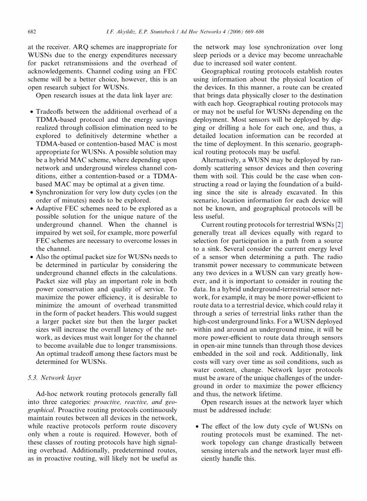
The current technology for underground sensingconsists of deploying a buried sensor, such as thatshown in Fig. 1, and wiring it to a data-logger onthe surface which stores sensor readings for later
.
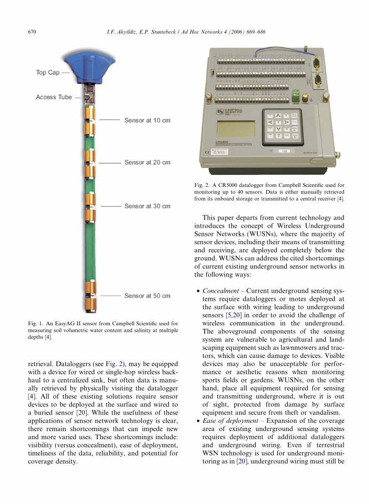
Fig. 1. An EasyAG II sensor from Campbell Scientific used formeasuring soil volumetric water content and salinity at multipledepths [4].
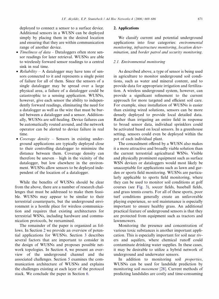
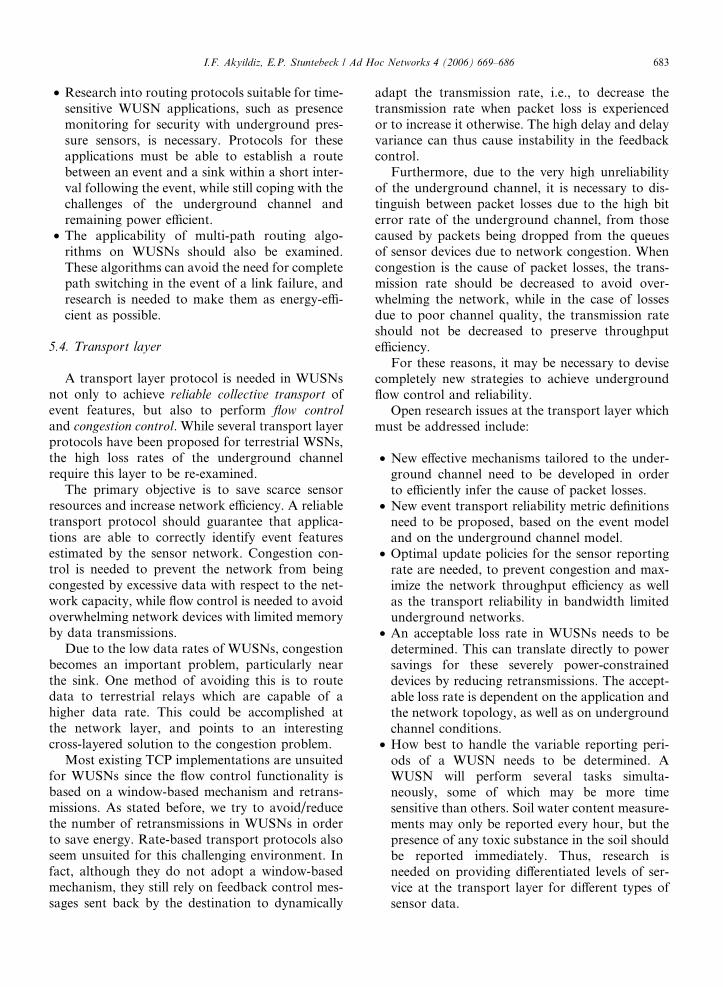
Fig. 2. A CR5000 datalogger from Campbell Scientific used formonitoring up to 40 sensors. Data is either manually retrievedfrom its onboard storage or transmitted to a central receiver [4].
670 I.F. Akyildiz, E.P. Stuntebeck / Ad Hoc Networks 4 (2006) 669–686
retrieval. Dataloggers (see Fig. 2), may be equippedwith a device for wired or single-hop wireless back-haul to a centralized sink, but often data is manu-ally retrieved by physically visiting the datalogger[4]. All of these existing solutions require sensordevices to be deployed at the surface and wired toa buried sensor [20]. While the usefulness of theseapplications of sensor network technology is clear,there remain shortcomings that can impede newand more varied uses. These shortcomings include:visibility (versus concealment), ease of deployment,timeliness of the data, reliability, and potential forcoverage density.
This paper departs from current technology andintroduces the concept of Wireless UndergroundSensor Networks (WUSNs), where the majority ofsensor devices, including their means of transmittingand receiving, are deployed completely below theground. WUSNs can address the cited shortcomingsof current existing underground sensor networks inthe following ways:
• Concealment – Current underground sensing sys-tems require dataloggers or motes deployed atthe surface with wiring leading to undergroundsensors [5,20] in order to avoid the challenge ofwireless communication in the underground.The aboveground components of the sensingsystem are vulnerable to agricultural and land-scaping equipment such as lawnmowers and trac-tors, which can cause damage to devices. Visibledevices may also be unacceptable for perfor-mance or aesthetic reasons when monitoringsports fields or gardens. WUSNs, on the otherhand, place all equipment required for sensingand transmitting underground, where it is outof sight, protected from damage by surfaceequipment and secure from theft or vandalism.
• Ease of deployment – Expansion of the coveragearea of existing underground sensing systemsrequires deployment of additional dataloggersand underground wiring. Even if terrestrialWSN technology is used for underground moni-toring as in [20], underground wiring must still be
I.F. Akyildiz, E.P. Stuntebeck / Ad Hoc Networks 4 (2006) 669–686 671
deployed to connect a sensor to a surface device.Additional sensors in a WUSN can be deployedsimply by placing them in the desired locationand ensuring that they are within communicationrange of another device.
• Timeliness of data – Dataloggers often store sen-sor readings for later retrieval. WUSNs are ableto wirelessly forward sensor readings to a centralsink in real time.
• Reliability – A datalogger may have tens of sen-sors connected to it and represents a single pointof failure for all of them. Since the sensors of asingle datalogger may be spread over a largephysical area, a failure of a datalogger could becatastrophic to a sensing application. WUSNs,however, give each sensor the ability to indepen-dently forward readings, eliminating the need fora datalogger as well as the wire that must be bur-ied between a datalogger and a sensor. Addition-ally, WUSNs are self-healing. Device failures canbe automatically routed around, and the networkoperator can be alerted to device failure in realtime.
• Coverage density – Sensors in existing under-ground applications are typically deployed closeto their controlling datalogger to minimize thedistance between them. Coverage density cantherefore be uneven – high in the vicinity of thedatalogger, but low elsewhere in the environ-ment. WUSNs allow sensors to be deployed inde-pendent of the location of a datalogger.
While the benefits of WUSNs should be clearfrom the above, there are a number of research chal-lenges that must be addressed to make them feasi-ble. WUSNs may appear to be similar to theirterrestrial counterparts, but the underground envi-ronment is a hostile place for wireless communica-tion and requires that existing architectures forterrestrial WSNs, including hardware and commu-nication protocols, be reexamined.
The remainder of the paper is organized as fol-lows. In Section 2 we provide an overview of poten-tial applications for WUSNs. Section 3 describesseveral factors that are important to consider inthe design of WUSNs and proposes possible net-work topologies. In Section 4, we present an over-view of the underground channel and theassociated challenges. Section 5 examines the com-munication architecture of WUSNs and explainsthe challenges existing at each layer of the protocolstack. We conclude the paper in Section 6.
2. Applications
We classify current and potential undergroundapplications into four categories: environmentalmonitoring, infrastructure monitoring, location deter-
mination, and border patrol and security monitoring.
2.1. Environmental monitoring
As described above, a type of sensor is being usedin agriculture to monitor underground soil condi-tions, such as water and mineral content, and toprovide data for appropriate irrigation and fertiliza-tion. A wireless underground system, however, canprovide a significant refinement to the currentapproach for more targeted and efficient soil care.For example, since installation of WUSNs is easierthan existing wired solutions, sensors can be moredensely deployed to provide local detailed data.Rather than irrigating an entire field in responseto broad sensor data, individual sprinklers couldbe activated based on local sensors. In a greenhousesetting, sensors could even be deployed within thepot of each individual plant.
The concealment offered by a WUSN also makesit a more attractive and broadly viable solution thanthe current terrestrial agricultural WSNs. Visibleand physically prominent equipment such as surfaceWSN devices or dataloggers would most likely beunacceptable for applications such as lawn and gar-den or sports field monitoring. WUSNs are particu-larly applicable to sports field monitoring, wherethey can be used to monitor soil conditions at golfcourses (see Fig. 3), soccer fields, baseball fields,and grass tennis courts. For all of these sports, poorturf conditions generally create an unfavorableplaying experience, so soil maintenance is especiallyimportant to ensure healthy grass. An additionalpractical feature of underground sensors is that theyare protected from equipment such as tractors andlawnmowers.
Monitoring the presence and concentration ofvarious toxic substances is another important appli-cation. This is especially important for soil near riv-ers and aquifers, where chemical runoff couldcontaminate drinking water supplies. In these cases,it may be desirable to utilize a hybrid network ofunderground and underwater sensors.
In addition to monitoring soil properties,WUSNs can be used for landslide prediction bymonitoring soil movement [28]. Current methods ofpredicting landslides are costly and time-consuming
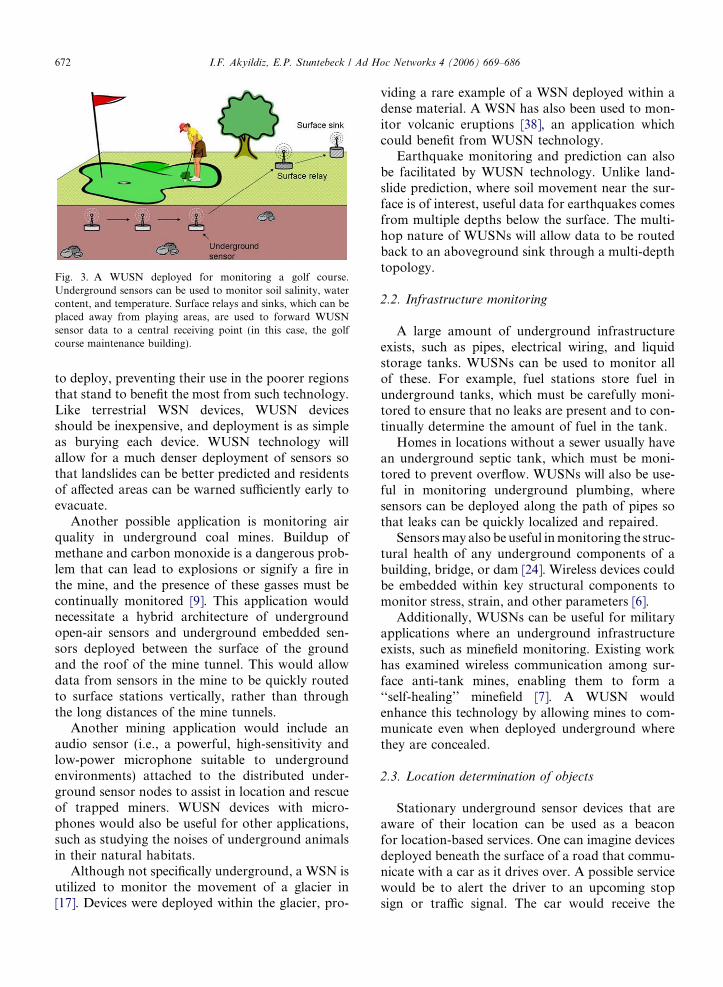
Fig. 3. A WUSN deployed for monitoring a golf course.Underground sensors can be used to monitor soil salinity, watercontent, and temperature. Surface relays and sinks, which can beplaced away from playing areas, are used to forward WUSNsensor data to a central receiving point (in this case, the golfcourse maintenance building).
672 I.F. Akyildiz, E.P. Stuntebeck / Ad Hoc Networks 4 (2006) 669–686
to deploy, preventing their use in the poorer regionsthat stand to benefit the most from such technology.Like terrestrial WSN devices, WUSN devicesshould be inexpensive, and deployment is as simpleas burying each device. WUSN technology willallow for a much denser deployment of sensors sothat landslides can be better predicted and residentsof affected areas can be warned sufficiently early toevacuate.
Another possible application is monitoring airquality in underground coal mines. Buildup ofmethane and carbon monoxide is a dangerous prob-lem that can lead to explosions or signify a fire inthe mine, and the presence of these gasses must becontinually monitored [9]. This application wouldnecessitate a hybrid architecture of undergroundopen-air sensors and underground embedded sen-sors deployed between the surface of the groundand the roof of the mine tunnel. This would allowdata from sensors in the mine to be quickly routedto surface stations vertically, rather than throughthe long distances of the mine tunnels.
Another mining application would include anaudio sensor (i.e., a powerful, high-sensitivity andlow-power microphone suitable to undergroundenvironments) attached to the distributed under-ground sensor nodes to assist in location and rescueof trapped miners. WUSN devices with micro-phones would also be useful for other applications,such as studying the noises of underground animalsin their natural habitats.
Although not specifically underground, a WSN isutilized to monitor the movement of a glacier in[17]. Devices were deployed within the glacier, pro-
viding a rare example of a WSN deployed within adense material. A WSN has also been used to mon-itor volcanic eruptions [38], an application whichcould benefit from WUSN technology.
Earthquake monitoring and prediction can alsobe facilitated by WUSN technology. Unlike land-slide prediction, where soil movement near the sur-face is of interest, useful data for earthquakes comesfrom multiple depths below the surface. The multi-hop nature of WUSNs will allow data to be routedback to an aboveground sink through a multi-depthtopology.
2.2. Infrastructure monitoring
A large amount of underground infrastructureexists, such as pipes, electrical wiring, and liquidstorage tanks. WUSNs can be used to monitor allof these. For example, fuel stations store fuel inunderground tanks, which must be carefully moni-tored to ensure that no leaks are present and to con-tinually determine the amount of fuel in the tank.
Homes in locations without a sewer usually havean underground septic tank, which must be moni-tored to prevent overflow. WUSNs will also be use-ful in monitoring underground plumbing, wheresensors can be deployed along the path of pipes sothat leaks can be quickly localized and repaired.
Sensors may also be useful in monitoring the struc-tural health of any underground components of abuilding, bridge, or dam [24]. Wireless devices couldbe embedded within key structural components tomonitor stress, strain, and other parameters [6].
Additionally, WUSNs can be useful for militaryapplications where an underground infrastructureexists, such as minefield monitoring. Existing workhas examined wireless communication among sur-face anti-tank mines, enabling them to form a‘‘self-healing’’ minefield [7]. A WUSN wouldenhance this technology by allowing mines to com-municate even when deployed underground wherethey are concealed.
2.3. Location determination of objects
Stationary underground sensor devices that areaware of their location can be used as a beaconfor location-based services. One can imagine devicesdeployed beneath the surface of a road that commu-nicate with a car as it drives over. A possible servicewould be to alert the driver to an upcoming stopsign or traffic signal. The car would receive the
I.F. Akyildiz, E.P. Stuntebeck / Ad Hoc Networks 4 (2006) 669–686 673
information about the upcoming signal and relaythis to the driver.
Location information could also serve as anavigational aid for autonomous systems, e.g., anautonomous fertilizer unit, which navigates aroundthe area to be fertilized based on underground loca-tion beacons and soil condition data from under-ground sensors.
WUSN technology can also be used to locatepeople in the event of a building collapse. Devicescould be deployed throughout a building and pro-grammed with their physical location. Buildingoccupants would then carry a device on their per-son. In the event of a collapse, the occupant’s devicecould be localized to a specific section of the build-ing by communicating with the stationary devices.This could provide rescuers with a general area tosearch for survivors. Although this application isnot strictly underground, the dense nature of therubble from a building collapse poses challenges towireless communication similar to soil.
2.4. Border patrol and security monitoring
WUSNs can be used to monitor the abovegroundpresence and movement of people or objects. Similarto location determination, deployed devices mustbe stationary and aware of their location. Unlikelocation determination, however, where objectsannounce their presence via direct communicationwith the embedded device, presence monitoringrequires the use of sensors, such as pressure, acoustic,or magnetic, to determine the presence of a person orobject. This application is useful for home and com-mercial security, where sensors could be deployedunderground around the perimeter of a building inorder to detect intruders. Since their presence is hid-den, intruders would be less likely to know about andthus take action to disable the security system.
On a larger scale, WUSNs can be very useful forborder patrol. Wireless pressure sensors deployed ata shallow depth along the length of a border couldbe used to alert authorities to illegal crossings. Eachsensor would be programmed with location infor-mation as it is deployed, allowing the exact locationof an illegal crossing to be easily determined andgiving a general area in which to deploy authoritiesfor a search. Rural areas are the ones needing themost security, and WUSN technology would allowa monitoring system to be easily deployed in theseareas without any necessary infrastructure sincethey are self-powered.
3. WUSN design challenges
WUSNs are an exciting research area because ofthe unique nature of the underground environment.From a severely impaired underground channel topractical considerations such as the size of a device’santenna, the underground forces us to rethink ter-restrial WSN paradigms. In this section, we describefour considerations for WUSN design necessitatedby this unique environment: power conservation,topology design, antenna design, and environmental
extremes.
3.1. Power conservation
Depending on the intended application, WUSNdevices should have a lifetime of at least severalyears in order to make their deployment cost-effi-cient. This challenge is complicated by the lossyunderground channel, which requires that WUSNdevices have radios with greater transmission powerthan terrestrial WSN devices. As a result, powerconservation is a primary concern in the design ofWUSNs.
Like terrestrial WSNs, the lifetime of WUSNs islimited by the self-contained power source of eachdevice. Unfortunately, access to WUSN devices willbe much more difficult than access to terrestrialWSN devices in most deployments, making retrievalof a device to recharge or replace its power supplyless feasible. While recharging of devices deployedclose to the surface may be possible with inductiontechniques, recharging deeper devices will be diffi-cult, if not impossible. Deployment of new devicesto replace failed ones is similarly difficult. Addition-ally, terrestrial WSN devices can be equipped with asolar cell [14,35] to supplement or even replace a tra-ditional power source, which is obviously not anoption for WUSN devices. Scavenging opportunitiesfor WUSN devices, such as converting seismic vibra-tions or thermal gradients to energy [22,27,30], doexist, but it remains to be explored whether thesemethods can provide sufficient energy to operate adevice in the absence of a traditional power supply.In [23], the state of the art in more unconventionaltechniques for energy scavenging is surveyed. Theauthors describe technologies to generate energyfrom background radio signals, thermoelectric con-version, and vibrational excitation.
Power conservation, therefore, should be a pri-mary objective in the design of WUSNs. While itis possible to increase the lifetime of a device by
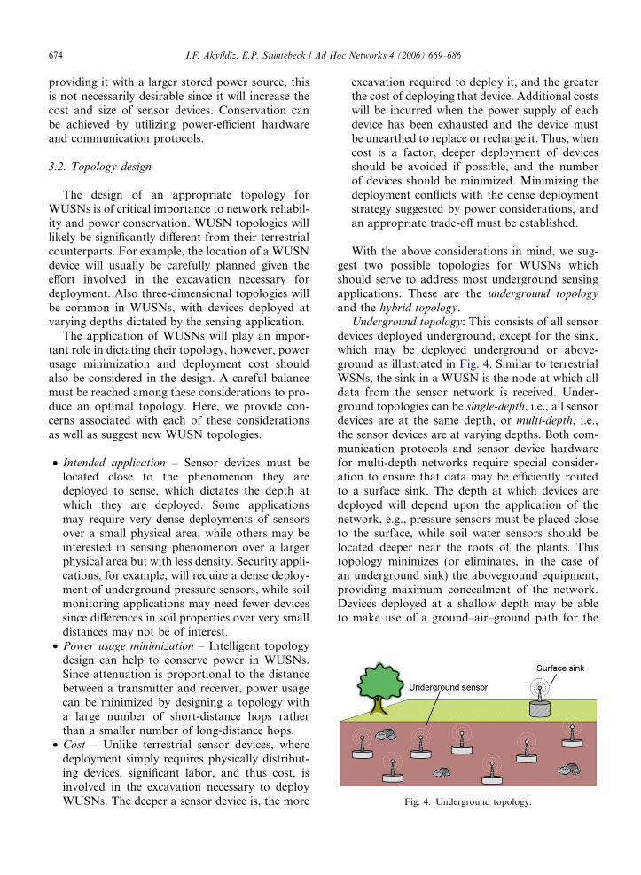
Fig. 4. Underground topology.
674 I.F. Akyildiz, E.P. Stuntebeck / Ad Hoc Networks 4 (2006) 669–686
providing it with a larger stored power source, thisis not necessarily desirable since it will increase thecost and size of sensor devices. Conservation canbe achieved by utilizing power-efficient hardwareand communication protocols.
3.2. Topology design
The design of an appropriate topology forWUSNs is of critical importance to network reliabil-ity and power conservation. WUSN topologies willlikely be significantly different from their terrestrialcounterparts. For example, the location of a WUSNdevice will usually be carefully planned given theeffort involved in the excavation necessary fordeployment. Also three-dimensional topologies willbe common in WUSNs, with devices deployed atvarying depths dictated by the sensing application.
The application of WUSNs will play an impor-tant role in dictating their topology, however, powerusage minimization and deployment cost shouldalso be considered in the design. A careful balancemust be reached among these considerations to pro-duce an optimal topology. Here, we provide con-cerns associated with each of these considerationsas well as suggest new WUSN topologies.
• Intended application – Sensor devices must belocated close to the phenomenon they aredeployed to sense, which dictates the depth atwhich they are deployed. Some applicationsmay require very dense deployments of sensorsover a small physical area, while others may beinterested in sensing phenomenon over a largerphysical area but with less density. Security appli-cations, for example, will require a dense deploy-ment of underground pressure sensors, while soilmonitoring applications may need fewer devicessince differences in soil properties over very smalldistances may not be of interest.
• Power usage minimization – Intelligent topologydesign can help to conserve power in WUSNs.Since attenuation is proportional to the distancebetween a transmitter and receiver, power usagecan be minimized by designing a topology witha large number of short-distance hops ratherthan a smaller number of long-distance hops.
• Cost – Unlike terrestrial sensor devices, wheredeployment simply requires physically distribut-ing devices, significant labor, and thus cost, isinvolved in the excavation necessary to deployWUSNs. The deeper a sensor device is, the more
excavation required to deploy it, and the greaterthe cost of deploying that device. Additional costswill be incurred when the power supply of eachdevice has been exhausted and the device mustbe unearthed to replace or recharge it. Thus, whencost is a factor, deeper deployment of devicesshould be avoided if possible, and the numberof devices should be minimized. Minimizing thedeployment conflicts with the dense deploymentstrategy suggested by power considerations, andan appropriate trade-off must be established.
With the above considerations in mind, we sug-gest two possible topologies for WUSNs whichshould serve to address most underground sensingapplications. These are the underground topology
and the hybrid topology.Underground topology: This consists of all sensor
devices deployed underground, except for the sink,which may be deployed underground or above-ground as illustrated in Fig. 4. Similar to terrestrialWSNs, the sink in a WUSN is the node at which alldata from the sensor network is received. Under-ground topologies can be single-depth, i.e., all sensordevices are at the same depth, or multi-depth, i.e.,the sensor devices are at varying depths. Both com-munication protocols and sensor device hardwarefor multi-depth networks require special consider-ation to ensure that data may be efficiently routedto a surface sink. The depth at which devices aredeployed will depend upon the application of thenetwork, e.g., pressure sensors must be placed closeto the surface, while soil water sensors should belocated deeper near the roots of the plants. Thistopology minimizes (or eliminates, in the case ofan underground sink) the aboveground equipment,providing maximum concealment of the network.Devices deployed at a shallow depth may be ableto make use of a ground–air–ground path for the
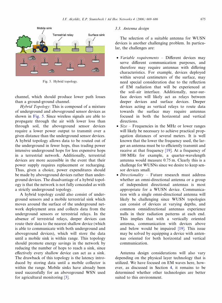
Fig. 5. Hybrid topology.
I.F. Akyildiz, E.P. Stuntebeck / Ad Hoc Networks 4 (2006) 669–686 675
channel, which should produce lower path lossesthan a ground-ground channel.
Hybrid Topology: This is composed of a mixtureof underground and aboveground sensor devices asshown in Fig. 5. Since wireless signals are able topropagate through the air with lower loss thanthrough soil, the aboveground sensor devicesrequire a lower power output to transmit over agiven distance than the underground sensor devices.A hybrid topology allows data to be routed out ofthe underground in fewer hops, thus trading powerintensive underground hops for less expensive hopsin a terrestrial network. Additionally, terrestrialdevices are more accessible in the event that theirpower supply requires replacement or recharging.Thus, given a choice, power expenditures shouldbe made by aboveground devices rather than under-ground devices. The disadvantage of a hybrid topol-ogy is that the network is not fully concealed as witha strictly underground topology.
A hybrid topology could also consist of under-ground sensors and a mobile terrestrial sink whichmoves around the surface of the underground net-work deployment area and collects data from theunderground sensors or terrestrial relays. In theabsence of terrestrial relays, deeper devices canroute their data to the nearest shallow device (whichis able to communicate with both underground andaboveground devices), which will store the datauntil a mobile sink is within range. This topologyshould promote energy savings in the network byreducing the number of hops to reach a sink, sinceeffectively every shallow device can act as a sink.The drawback of this topology is the latency intro-duced by storing data until a mobile collector iswithin the range. Mobile sinks have already beenused successfully for an aboveground WSN usedfor agricultural monitoring [3].
3.3. Antenna design
The selection of a suitable antenna for WUSNdevices is another challenging problem. In particu-lar, the challenges are:
• Variable requirements – Different devices mayserve different communication purposes, andtherefore may require antennas with differingcharacteristics. For example, devices deployedwithin several centimeters of the surface, mayneed special consideration due to the reflectionof EM radiation that will be experienced atthe soil–air interface. Additionally, near-sur-face devices will likely act as relays betweendeeper devices and surface devices. Deeperdevices acting as vertical relays to route datatowards the surface may require antennasfocused in both the horizontal and verticaldirections.
• Size – Frequencies in the MHz or lower rangeswill likely be necessary to achieve practical prop-agation distances of several meters. It is wellknown that the lower the frequency used, the lar-ger an antenna must be to efficiently transmit andreceive at that frequency [19]. At a frequency of100 MHz for example, a quarter-wavelengthantenna would measure 0.75 m. Clearly this is achallenge for WUSNs since we desire to keep sen-sor devices small.
• Directionality – Future research must addresswhether an omni-directional antenna or a groupof independent directional antennas is mostappropriate for a WUSN device. Communica-tion with a single omni-directional antenna willlikely be challenging since WUSN topologiescan consist of devices at varying depths, andcommon omnidirectional antennas experiencenulls in their radiation patterns at each end.This implies that with a vertically orientedantenna, communication with devices aboveand below would be impaired [19]. This issuemay be solved by equipping a device with anten-nas oriented for both horizontal and verticalcommunication.
Antenna design considerations will also varydepending on the physical layer technology that isutilized. We have focused on EM waves here, how-ever, as discussed in Section 4, it remains to bedetermined whether other technologies are bettersuited to this environment.
1.4 1.6 1.8 2 2.2 2.4 2.6 2.8 320
40
60
80
100
120
140
160
180
200
Pat
h Lo
ss (
dB)
Frequency (GHz)
5%10%15%20%25%Free space
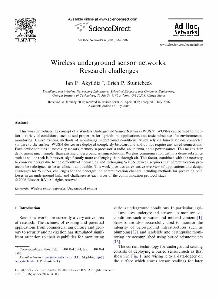
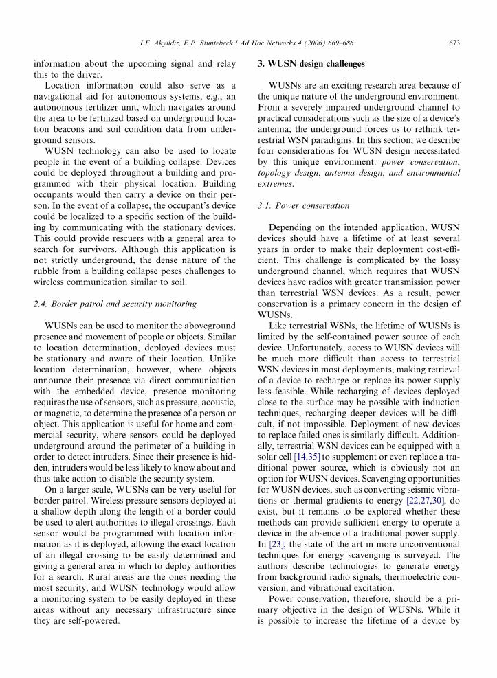
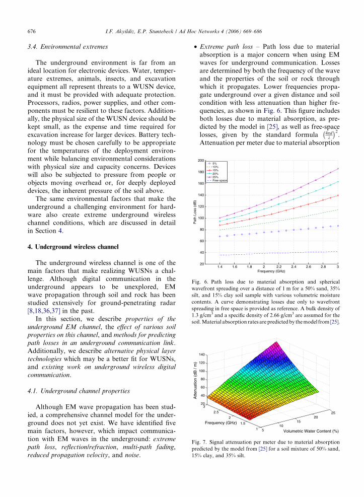
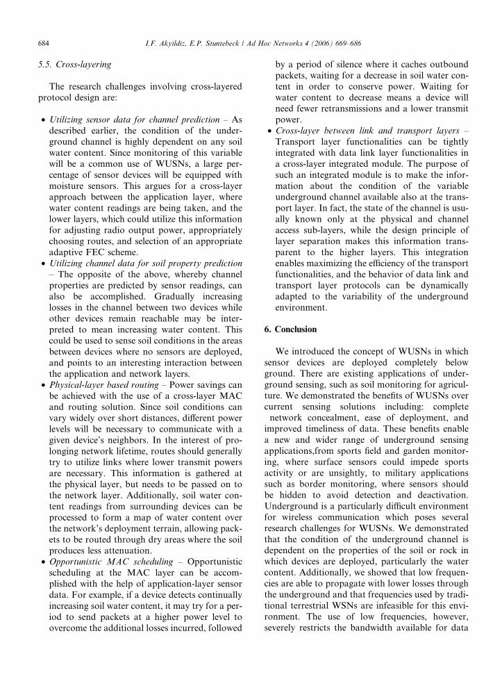
Fig. 6. Path loss due to material absorption and sphericalwavefront spreading over a distance of 1 m for a 50% sand, 35%silt, and 15% clay soil sample with various volumetric moisturecontents. A curve demonstrating losses due only to wavefrontspreading in free space is provided as reference. A bulk density of1.3 g/cm3 and a specific density of 2.66 g/cm3 are assumed for thesoil. Material absorption rates are predicted by the model from [25].
510
1520
25
1
1.5
2
2.5
320
40
60
80
100
120
140
Volumetric Water Content (%)
Frequency (GHz)
Atte
nuat
ion
(dB
/ m
)
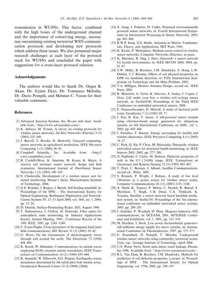
Fig. 7. Signal attenuation per meter due to material absorptionpredicted by the model from [25] for a soil mixture of 50% sand,15% clay, and 35% silt.
676 I.F. Akyildiz, E.P. Stuntebeck / Ad Hoc Networks 4 (2006) 669–686
3.4. Environmental extremes
The underground environment is far from anideal location for electronic devices. Water, temper-ature extremes, animals, insects, and excavationequipment all represent threats to a WUSN device,and it must be provided with adequate protection.Processors, radios, power supplies, and other com-ponents must be resilient to these factors. Addition-ally, the physical size of the WUSN device should bekept small, as the expense and time required forexcavation increase for larger devices. Battery tech-nology must be chosen carefully to be appropriatefor the temperatures of the deployment environ-ment while balancing environmental considerationswith physical size and capacity concerns. Deviceswill also be subjected to pressure from people orobjects moving overhead or, for deeply deployeddevices, the inherent pressure of the soil above.
The same environmental factors that make theunderground a challenging environment for hard-ware also create extreme underground wirelesschannel conditions, which are discussed in detailin Section 4.
4. Underground wireless channel
The underground wireless channel is one of themain factors that make realizing WUSNs a chal-lenge. Although digital communication in theunderground appears to be unexplored, EMwave propagation through soil and rock has beenstudied extensively for ground-penetrating radar[8,18,36,37] in the past.
In this section, we describe properties of the
underground EM channel, the effect of various soilproperties on this channel, and methods for predicting
path losses in an underground communication link.Additionally, we describe alternative physical layer
technologies which may be a better fit for WUSNs,and existing work on underground wireless digital
communication.
4.1. Underground channel properties
Although EM wave propagation has been stud-ied, a comprehensive channel model for the under-ground does not yet exist. We have identified fivemain factors, however, which impact communica-tion with EM waves in the underground: extreme
path loss, reflection/refraction, multi-path fading,reduced propagation velocity, and noise.
• Extreme path loss – Path loss due to materialabsorption is a major concern when using EMwaves for underground communication. Lossesare determined by both the frequency of the waveand the properties of the soil or rock throughwhich it propagates. Lower frequencies propa-gate underground over a given distance and soilcondition with less attenuation than higher fre-quencies, as shown in Fig. 6. This figure includesboth losses due to material absorption, as pre-dicted by the model in [25], as well as free-spacelosses, given by the standard formula 4pd
k
� �2.
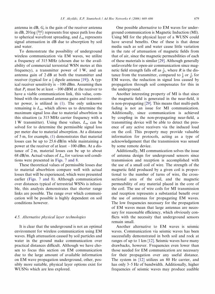
Attenuation per meter due to material absorption
010
2030
4050
010
2030
405010
20
30
40
50
60
70
80
90
Sand Particles (%)Clay Particles (%)
Atte
nuat
ion
(dB
/ m
)
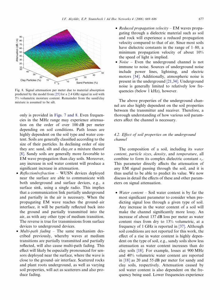
Fig. 8. Signal attenuation per meter due to material absorptionpredicted by the model from [25] for a 2.4 GHz signal in soil with5% volumetric moisture content. Remainder from the sand/claymixture is assumed to be silt.
I.F. Akyildiz, E.P. Stuntebeck / Ad Hoc Networks 4 (2006) 669–686 677
only is provided in Figs. 7 and 8. Even frequen-cies in the MHz range may experience attenua-tion on the order of over 100 dB per meterdepending on soil conditions. Path losses arehighly dependent on the soil type and water con-tent. Soils are generally classified according to thesize of their particles. In declining order of sizethey are: sand, silt and clay,or a mixture thereof[8]. Sandy soils are generally more favorable toEM wave propagation than clay soils. Moreover,any increase in soil water content will produce asignificant increase in attenuation.
• Reflection/refraction – WUSN devices deployednear the surface are able to communicate withboth underground and surface devices, e.g., asurface sink, using a single radio. This impliesthat a communication link partially undergroundand partially in the air is necessary. When thepropagating EM wave reaches the ground–airinterface, it will be partially reflected back intothe ground and partially transmitted into theair, as with any other type of medium transition.The reverse is true for transmissions from surfacedevices to underground devices.
• Multi-path fading – The same mechanism des-cribed previously, whereby waves at mediumtransitions are partially transmitted and partiallyreflected, will also cause multi-path fading. Thiseffect will likely be especially pronounced for sen-sors deployed near the surface, where the wave isclose to the ground–air interface. Scattered rocksand plant roots underground, as well as varyingsoil properties, will act as scatterers and also pro-duce fading.
• Reduced propagation velocity – EM waves propa-gating through a dielectric material such as soiland rock will experience a reduced propagationvelocity compared to that of air. Since most soilshave dielectric constants in the range of 1–80, aminimum propagation velocity of about 10%the speed of light is implied.
• Noise – Even the underground channel is notimmune to noise. Sources of underground noiseinclude power lines, lightning, and electricmotors [34]. Additionally, atmospheric noise ispresent in the underground [21,34]. Undergroundnoise is generally limited to relatively low fre-quencies (below 1 kHz), however.
The above properties of the underground chan-nel are also highly dependent on the soil propertiesbetween the transmitter and receiver. Therefore, athorough understanding of how various soil param-eters affect the channel is necessary.
4.2. Effect of soil properties on the underground
channel
The composition of a soil, including its water
content, particle sizes, density, and temperature, allcombine to form its complex dielectric constant �r.This parameter directly affects the attenuation ofany EM signal passing through the soil, and it isthus useful to be able to predict its value. We nowdiscuss in detail the effects of these and other param-eters on signal attenuation.
• Water content – Soil water content is by far themost significant parameter to consider when pre-dicting signal loss through a given type of soil.Any increase in the water content of a soil willmake the channel significantly more lossy. Anincrease of about 137 dB loss per meter as watercontent rises from dry to 13% volumetric, at afrequency of 1 GHz is reported in [37]. Althoughsoil conditions are not reported for this work, theeffect of a rise in water content is highly depen-dent on the type of soil, e.g., sandy soils show lessattenuation as water content increases than doclay soils [18]. For example, losses at 900 MHzand 40% volumetric water content are reportedin [18] as 20 and 55 dB per meter for sandy andclay soils, respectively. Attenuation caused bysoil water content is also dependent on the fre-quency being used. Lower frequencies experience
678 I.F. Akyildiz, E.P. Stuntebeck / Ad Hoc Networks 4 (2006) 669–686
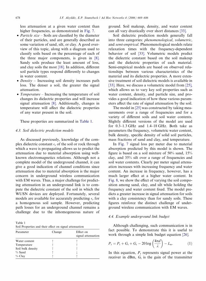
less attenuation at a given water content thanhigher frequencies, as demonstrated in Fig. 7.
• Particle size – Soils are classified by the diameterof their particles, and are generally described assome variation of sand, silt, or clay. A good over-view of this topic, along with a diagram used toclassify soils based on the percentage of each ofthe three major components, is given in [8].Sandy soils produce the least amount of loss,and clay soils the most [18]. In addition, differentsoil particle types respond differently to changesin water content.
• Density – Increasing soil density increases pathloss. The denser a soil, the greater the signalattenuation.
• Temperature – Increasing the temperature of soilchanges its dielectric properties and will increasesignal attenuation [8]. Additionally, changes intemperature will affect the dielectric propertiesof any water present in the soil.
These properties are summarized in Table 1.
4.3. Soil dielectric prediction models
As discussed previously, knowledge of the com-plex dielectric constant �r of the soil or rock throughwhich a wave is propagating allows us to predict theattenuation due to material absorption using well-known electromagnetics relations. Although not acomplete model of the underground channel, it cangive a good indication of channel conditions sinceattenuation due to material absorption is the majorconcern in underground wireless communicationwith EM waves. Thus, a major challenge for predict-ing attenuation in an underground link is to com-pute the dielectric constant of the soil in which theWUSN devices are deployed. Fortunately, severalmodels are available for accurately predicting �r fora homogenous soil sample. However, predictingpath losses for an underground channel remains achallenge due to the inhomogeneous nature of
Table 1Soil Properties and their effect on signal attenuation
Parameter Change Effect onsignal attenuation
Water content " "Temperature " "Soil bulk density " "% Sand " #% Clay " "
ground. Soil makeup, density, and water contentcan all vary drastically over short distances [33].
Soil dielectric prediction models generally fallinto three categories: phenomenological, volumetric,and semi-empirical. Phenomenological models relaterelaxation times with the frequency-dependentbehavior of soil [33]. Volumetric models predictthe dielectric constant based on the soil makeupand the dielectric properties of each material.Semi-empirical models are based on observed rela-tionships between various characteristics of thematerial and its dielectric properties. A more exten-sive treatment of soil dielectric models is available in[33]. Here, we discuss a volumetric model from [25],which allows us to vary key soil properties such aswater content, density, and particle size, and pro-vides a good indication of how these various param-eters affect the rate of signal attenuation by the soil.
The model in [25] was constructed by taking mea-surements over a range of frequencies and for avariety of different soils and soil water contents.Slightly different versions of the model are usedfor 0.3–1.3 GHz and 1.4–18 GHz. Both take asparameters the frequency, volumetric water content,bulk density, specific density of solid soil particles,mass fractions of sand and clay, and temperature.
In Fig. 7 signal loss per meter due to materialabsorption predicted by this model is shown. Thefigure is based on a soil mixture of 50% sand, 15%clay, and 35% silt over a range of frequencies andsoil water contents. Clearly per meter signal attenu-ation increases with increasing frequency and watercontent. An increase in frequency, however, has amuch larger effect at a higher water content. InFig. 8, we show the effect of varying the soil compo-sition among sand, clay, and silt while holding thefrequency and water content fixed. The model pre-dicts a greater increase in signal attenuation for soilswith a clay consistency than for sandy soils. Thesefigures reinforce the distinct challenge of under-ground wireless communication with EM waves.
4.4. Example underground link budget
Although challenging, such communication is infact possible. To demonstrate this it is useful towork through a simple link budget equation [26].
P r ¼ P t þ Gt þ Gr � 20 log4pdk
� �� Lm: ð1Þ
In this equation, Pr represents signal power at thereceiver in dBm, Gt is the gain of the transmitter
I.F. Akyildiz, E.P. Stuntebeck / Ad Hoc Networks 4 (2006) 669–686 679
antenna in dB, Gr is the gain of the receiver antennain dB, 20 log 4pd
k
� �represents free space path loss due
to spherical wavefront spreading, and Lm representssignal attenuation in dB due to absorption by soiland water.
To demonstrate the possibility of undergroundwireless communication via EM waves, we utilizea frequency of 315 MHz (chosen due to the avail-ability of commercial terrestrial WSN motes at thisfrequency), a transmitter power of 1 W, and anantenna gain of 2 dB at both the transmitter andreceiver (typical for a k
2dipole antenna [19]). A typ-
ical receiver sensitivity is �100 dBm. Assuming thenthat Pr must be at least �100 dBM at the receiver tohave a viable communication link, this value, com-bined with the assumed antenna gains and transmit-ter power, is utilized in (1). The only unknownremaining is Lm, which allows us to determine themaximum signal loss due to material absorbtion inthis situation (a 315 MHz carrier frequency with a1 W transmitter). Using these values, Lm can besolved for to determine the permissible signal lossper meter due to material absorption. At a distanceof 5 m, for example, (1) demonstrates that materiallosses can be up to 25.6 dB/m while maintaining apower at the receiver of at least �100 dBm. At a dis-tance of 2 m, material losses can be up to about68 dB/m. Actual values of Lm for various soil condi-tions were presented in Figs. 7 and 8.
These theoretical values of permissible losses dueto material absorbtion compare well with actuallosses that will be experienced, which were presentedearlier (Figs. 7 and 8). Although communicationover distances typical of terrestrial WSNs is infeasi-ble, this analysis demonstrates that shorter rangelinks are possible. The range over which communi-cation will be possible is highly dependent on soilconditions however.
4.5. Alternative physical layer technologies
It is clear that the underground is not an optimalenvironment for wireless communication using EMwaves. High attenuation caused by soil particles andwater in the ground make communication overpractical distances difficult. Although we have cho-sen to focus this section on EM communicationdue to the large amount of available informationon EM wave propagation underground, other, pos-sibly more suitable, physical layer options exist forWUSNs which are less explored.
One possible alternative to EM waves for under-ground communication is Magnetic Induction (MI).Using MI for the physical layer of a WUSN couldhave several benefits. One of these is that densemedia such as soil and water cause little variationin the rate of attenuation of magnetic fields fromthat of air, since the magnetic permeabilities of eachof these materials is similar [29]. Although generallyunfavorable for open-air communication since mag-netic field strength falls off as 1
R3, where R is the dis-tance from the transmitter, compared to 1
R or 1R2 for
EM waves, the reduction in signal loss caused bypropagation through soil compensates for this inthe underground.
Another interesting property of MI is that sincethe magnetic field is generated in the near-field, itis non-propagating [29]. This means that multi-pathfading is not an issue for MI communication.Additionally, since communication is achievedby coupling in the non-propagating near-field, atransmitting device will be able to detect the pres-ence of any active receivers via the induced loadon the coil. This property may provide valuableinformation for protocols, acting as a type ofacknowledgement that the transmission was sensedby some remote device.
Additionally, MI communication solves the issueof antenna design for underground sensors sincetransmission and reception is accomplished withthe use of a small coil of wire. The strength of themagnetic field produced by a given coil is propor-tional to the number of turns of wire, the cross-sectional area of the coil, and the magneticpermeability of any material placed in the core ofthe coil. The use of wire coils for MI transmissionand reception represents a substantial benefit overthe use of antennas for propagating EM waves.The low frequencies necessary for the propagationof EM waves mean that large antennas are neces-sary for reasonable efficiency, which obviously con-flicts with the necessity that underground sensorsremain small.
Another alternative to EM waves is seismicwaves. Communication via seismic waves has beensuccessfully demonstrated in both soil and rock atranges of up to 1 km [12]. Seismic waves have manydrawbacks, however. Frequencies even lower thanthose needed for EM communication are necessaryfor their propagation over any useful distance.The system in [12] utilizes an 80 Hz carrier, andhas only 3–5 Hz of bandwidth. Additionally, higherfrequencies of seismic waves may produce audible
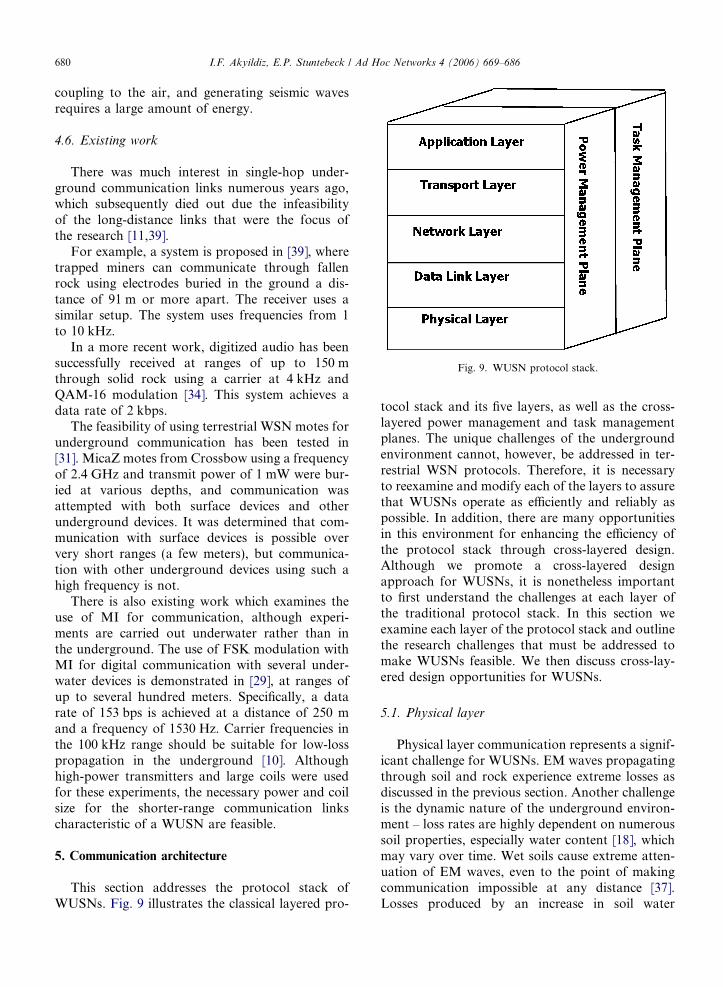
Fig. 9. WUSN protocol stack.
680 I.F. Akyildiz, E.P. Stuntebeck / Ad Hoc Networks 4 (2006) 669–686
coupling to the air, and generating seismic wavesrequires a large amount of energy.
4.6. Existing work
There was much interest in single-hop under-ground communication links numerous years ago,which subsequently died out due the infeasibilityof the long-distance links that were the focus ofthe research [11,39].
For example, a system is proposed in [39], wheretrapped miners can communicate through fallenrock using electrodes buried in the ground a dis-tance of 91 m or more apart. The receiver uses asimilar setup. The system uses frequencies from 1to 10 kHz.
In a more recent work, digitized audio has beensuccessfully received at ranges of up to 150 mthrough solid rock using a carrier at 4 kHz andQAM-16 modulation [34]. This system achieves adata rate of 2 kbps.
The feasibility of using terrestrial WSN motes forunderground communication has been tested in[31]. MicaZ motes from Crossbow using a frequencyof 2.4 GHz and transmit power of 1 mW were bur-ied at various depths, and communication wasattempted with both surface devices and otherunderground devices. It was determined that com-munication with surface devices is possible oververy short ranges (a few meters), but communica-tion with other underground devices using such ahigh frequency is not.
There is also existing work which examines theuse of MI for communication, although experi-ments are carried out underwater rather than inthe underground. The use of FSK modulation withMI for digital communication with several under-water devices is demonstrated in [29], at ranges ofup to several hundred meters. Specifically, a datarate of 153 bps is achieved at a distance of 250 mand a frequency of 1530 Hz. Carrier frequencies inthe 100 kHz range should be suitable for low-losspropagation in the underground [10]. Althoughhigh-power transmitters and large coils were usedfor these experiments, the necessary power and coilsize for the shorter-range communication linkscharacteristic of a WUSN are feasible.
5. Communication architecture
This section addresses the protocol stack ofWUSNs. Fig. 9 illustrates the classical layered pro-
tocol stack and its five layers, as well as the cross-layered power management and task managementplanes. The unique challenges of the undergroundenvironment cannot, however, be addressed in ter-restrial WSN protocols. Therefore, it is necessaryto reexamine and modify each of the layers to assurethat WUSNs operate as efficiently and reliably aspossible. In addition, there are many opportunitiesin this environment for enhancing the efficiency ofthe protocol stack through cross-layered design.Although we promote a cross-layered designapproach for WUSNs, it is nonetheless importantto first understand the challenges at each layer ofthe traditional protocol stack. In this section weexamine each layer of the protocol stack and outlinethe research challenges that must be addressed tomake WUSNs feasible. We then discuss cross-lay-ered design opportunities for WUSNs.
5.1. Physical layer
Physical layer communication represents a signif-icant challenge for WUSNs. EM waves propagatingthrough soil and rock experience extreme losses asdiscussed in the previous section. Another challengeis the dynamic nature of the underground environ-ment – loss rates are highly dependent on numeroussoil properties, especially water content [18], whichmay vary over time. Wet soils cause extreme atten-uation of EM waves, even to the point of makingcommunication impossible at any distance [37].Losses produced by an increase in soil water
I.F. Akyildiz, E.P. Stuntebeck / Ad Hoc Networks 4 (2006) 669–686 681
content, after a rainfall for example, can last for asignificant amount of time.
Given the challenging nature of EM wave prop-agation in the underground, designing an efficientantenna is very important. Embedding an antennain a conductive medium such as soil can signifi-cantly affect its radiation and reception characteris-tics [15]. As previously discussed, when propagatingthrough soil and rock, lower frequencies of EMwaves experience less attenuation than higher fre-quencies [36], so communication at practical dis-tances of several meters will likely only be feasiblewhen using these lower frequencies. TraditionalEM antennas are much too large for a WUSNdevice at the low frequencies of interest.
Given the power constraints of WUSN devicesand the necessity of using low frequencies to reducepath losses as explained in the previous section, theselection of an appropriate modulation scheme inWUSNs is another challenge. Earlier works thathave addressed underground wireless communica-tion have focused solely on analog communication.One exception is [34], which reports success usingQPSK, QAM-16 and QAM-32 modulation schemeswith a 4 kHz carrier and 10 W of transmit power. Adata rate of 2 kbps is achieved. Aside from thiswork, modulation schemes for underground com-munication continue to be an unexplored area.
The use of a lower carrier frequency means thatless bandwidth is available for data transmission,so WUSNs will be constrained to a lower data ratethan terrestrial WSNs. Extreme channel losses willalso affect the data rate in WUSNs.
Open research issues at the physical layer are:
• Additional analysis of electromagnetic, magneticinduction (MI), and seismic communication inthe underground needs to be carried out to iden-tify the most appropriate physical layer technol-ogy. Some combination of these technologiesmay be optimal, particularly for shallow sensordevices which must communicate with bothunderground and surface devices.
• A power-efficient modulation scheme suitable forthe dynamic high-loss underground channel mustbe chosen. Research into varying the modulationscheme depending on underground channel con-ditions is needed. After a rainfall when the chan-nel is severely impaired, for example, it may bebetter to trade higher data rates for a simplermodulation scheme. Modulation schemes requir-ing channel estimation by means of probe pack-
ets should be avoided due to the energyoverhead involved in probe transmission.
• The trade-off between reliability and capacitymust be examined. Lower frequencies propagatewith lower loss over a given distance underground,but also have less available bandwidth for datatransmission reducing the channel capacity.
• An information theoretical study of the capacityof underground wireless communication chan-nels is needed.
5.2. Data link layer
Existing MAC protocols [16] intended for terres-trial WSNs will likely perform poorly in WUSNs.These protocols for terrestrial WSNs are typicallyeither contention-based or TDMA-based, and focuson minimizing energy consumption by addressingfour primary areas: idle listening, collisions, control
packet overhead, and overhearing [16]. WUSNsrequire special consideration for MAC protocoldevelopment due to the characteristics of the under-ground wireless channel which we explained indetail in Section 4.
Although energy conservation is the main focusof existing MAC protocols for terrestrial WSNs,energy savings are captured by reducing idle listen-ing time [16]. In WUSNs, radios must transmit witha much higher output power than in the terrestrialWSNs in order to overcome path losses incurredin the ground. In order for underground sensorsto have an acceptable lifetime, the number of trans-missions must be minimized.
Since collisions cause retransmissions, a WUSNMAC protocol should avoid collisions. Althoughthis may be accomplished with a contention-basedprotocol using an RTS/CTS type scheme, this intro-duces unacceptable overhead in WUSNs.
On the other hand, a TDMA-based scheme isable to eliminate collisions by reserving a timeslotfor each device to transmit. However, in this casesynchronization becomes a concern, and introducesits own overhead.
Since WUSN devices will likely report sensordata infrequently, they can operate with a low dutycycle to save power. Unfortunately, a device’sclock may drift a large amount during these peri-ods of sleep and the network may loose itssynchronization.
Due to the lossy nature of the underground chan-nel and energy constraints of sensor devices, signalswill likely have relatively high bit error rates (BER)
682 I.F. Akyildiz, E.P. Stuntebeck / Ad Hoc Networks 4 (2006) 669–686
at the receiver. ARQ schemes are inappropriate forWUSNs due to the energy expenditures necessaryfor packet retransmissions and the overhead ofacknowledgements. Channel coding using an FECscheme will be a better choice, however, this is anopen research subject for WUSNs.
Open research issues at the data link layer are:
• Tradeoffs between the additional overhead of aTDMA-based protocol and the energy savingsrealized through collision elimination need to beexplored to definitively determine whether aTDMA-based or contention-based MAC is mostappropriate for WUSNs. A possible solution maybe a hybrid MAC scheme, where depending uponnetwork and underground wireless channel con-ditions, either a contention-based or a TDMA-based MAC may be optimal at a given time.
• Synchronization for very low duty cycles (on theorder of minutes) needs to be explored.
• Adaptive FEC schemes need to be explored as apossible solution for the unique nature of theunderground channel. When the channel isimpaired by wet soil, for example, more powerfulFEC schemes are necessary to overcome losses inthe channel.
• Also the optimal packet size for WUSNs needs tobe determined in particular by considering theunderground channel effects in the calculations.Packet size will play an important role in bothpower conservation and quality of service. Tomaximize the power efficiency, it is desirable tominimize the amount of overhead transmittedin the form of packet headers. This would suggesta larger packet size but then the larger packetsizes will increase the overall latency of the net-work, as devices must wait longer for the channelto become available due to longer transmissions.An optimal tradeoff among these factors must bedetermined for WUSNs.
5.3. Network layer
Ad-hoc network routing protocols generally fallinto three categories: proactive, reactive, and geo-
graphical. Proactive routing protocols continuouslymaintain routes between all devices in the network,while reactive protocols perform route discoveryonly when a route is required. However, both ofthese classes of routing protocols have high signal-ing overhead. Additionally, predetermined routes,as in proactive routing, will likely not be useful as
the network may lose synchronization over longsleep periods or a device may become unreachabledue to increased soil water content.
Geographical routing protocols establish routesusing information about the physical location ofthe devices. In this manner, a route can be createdthat brings data physically closer to the destinationwith each hop. Geographical routing protocols mayor may not be useful for WUSNs depending on thedeployment. Most sensors will be deployed by dig-ging or drilling a hole for each one, and thus, adetailed location information can be recorded atthe time of deployment. In this scenario, geograph-ical routing protocols may be useful.
Alternatively, a WUSN may be deployed by ran-domly scattering sensor devices and then coveringthem with soil. This could be the case when con-structing a road or laying the foundation of a build-ing since the site is already excavated. In thisscenario, location information for each device willnot be known, and geographical protocols will beless useful.
Current routing protocols for terrestrial WSNs [2]generally treat all devices equally with regard toselection for participation in a path from a sourceto a sink. Several consider the current energy levelof a sensor when determining a path. The radiotransmit power necessary to communicate betweenany two devices in a WUSN can vary greatly how-ever, and it is important to consider in routing thedata. In a hybrid underground-terrestrial sensor net-work, for example, it may be more power-efficient toroute data to a terrestrial device, which could relay itthrough a series of terrestrial links rather than thehigh-cost underground links. For a WUSN deployedwithin and around an underground mine, it will bemore power-efficient to route data through sensorsin open-air mine tunnels than through those devicesembedded in the soil and rock. Additionally, linkcosts will vary over time as soil conditions, such aswater content, change. Network layer protocolsmust be aware of the unique challenges of the under-ground in order to maximize the power efficiencyand thus, the network lifetime.
Open research issues at the network layer whichmust be addressed include:
• The effect of the low duty cycle of WUSNs onrouting protocols must be examined. The net-work topology can change drastically betweensensing intervals and the network layer must effi-ciently handle this.
I.F. Akyildiz, E.P. Stuntebeck / Ad Hoc Networks 4 (2006) 669–686 683
• Research into routing protocols suitable for time-sensitive WUSN applications, such as presencemonitoring for security with underground pres-sure sensors, is necessary. Protocols for theseapplications must be able to establish a routebetween an event and a sink within a short inter-val following the event, while still coping with thechallenges of the underground channel andremaining power efficient.
• The applicability of multi-path routing algo-rithms on WUSNs should also be examined.These algorithms can avoid the need for completepath switching in the event of a link failure, andresearch is needed to make them as energy-effi-cient as possible.
5.4. Transport layer
A transport layer protocol is needed in WUSNsnot only to achieve reliable collective transport ofevent features, but also to perform flow control
and congestion control. While several transport layerprotocols have been proposed for terrestrial WSNs,the high loss rates of the underground channelrequire this layer to be re-examined.
The primary objective is to save scarce sensorresources and increase network efficiency. A reliabletransport protocol should guarantee that applica-tions are able to correctly identify event featuresestimated by the sensor network. Congestion con-trol is needed to prevent the network from beingcongested by excessive data with respect to the net-work capacity, while flow control is needed to avoidoverwhelming network devices with limited memoryby data transmissions.
Due to the low data rates of WUSNs, congestionbecomes an important problem, particularly nearthe sink. One method of avoiding this is to routedata to terrestrial relays which are capable of ahigher data rate. This could be accomplished atthe network layer, and points to an interestingcross-layered solution to the congestion problem.
Most existing TCP implementations are unsuitedfor WUSNs since the flow control functionality isbased on a window-based mechanism and retrans-missions. As stated before, we try to avoid/reducethe number of retransmissions in WUSNs in orderto save energy. Rate-based transport protocols alsoseem unsuited for this challenging environment. Infact, although they do not adopt a window-basedmechanism, they still rely on feedback control mes-sages sent back by the destination to dynamically
adapt the transmission rate, i.e., to decrease thetransmission rate when packet loss is experiencedor to increase it otherwise. The high delay and delayvariance can thus cause instability in the feedbackcontrol.
Furthermore, due to the very high unreliabilityof the underground channel, it is necessary to dis-tinguish between packet losses due to the high biterror rate of the underground channel, from thosecaused by packets being dropped from the queuesof sensor devices due to network congestion. Whencongestion is the cause of packet losses, the trans-mission rate should be decreased to avoid over-whelming the network, while in the case of lossesdue to poor channel quality, the transmission rateshould not be decreased to preserve throughputefficiency.
For these reasons, it may be necessary to devisecompletely new strategies to achieve undergroundflow control and reliability.
Open research issues at the transport layer whichmust be addressed include:
• New effective mechanisms tailored to the under-ground channel need to be developed in orderto efficiently infer the cause of packet losses.
• New event transport reliability metric definitionsneed to be proposed, based on the event modeland on the underground channel model.
• Optimal update policies for the sensor reportingrate are needed, to prevent congestion and max-imize the network throughput efficiency as wellas the transport reliability in bandwidth limitedunderground networks.
• An acceptable loss rate in WUSNs needs to bedetermined. This can translate directly to powersavings for these severely power-constraineddevices by reducing retransmissions. The accept-able loss rate is dependent on the application andthe network topology, as well as on undergroundchannel conditions.
• How best to handle the variable reporting peri-ods of a WUSN needs to be determined. AWUSN will perform several tasks simulta-neously, some of which may be more timesensitive than others. Soil water content measure-ments may only be reported every hour, but thepresence of any toxic substance in the soil shouldbe reported immediately. Thus, research isneeded on providing differentiated levels of ser-vice at the transport layer for different types ofsensor data.
684 I.F. Akyildiz, E.P. Stuntebeck / Ad Hoc Networks 4 (2006) 669–686
5.5. Cross-layering
The research challenges involving cross-layeredprotocol design are:
• Utilizing sensor data for channel prediction – Asdescribed earlier, the condition of the under-ground channel is highly dependent on any soilwater content. Since monitoring of this variablewill be a common use of WUSNs, a large per-centage of sensor devices will be equipped withmoisture sensors. This argues for a cross-layerapproach between the application layer, wherewater content readings are being taken, and thelower layers, which could utilize this informationfor adjusting radio output power, appropriatelychoosing routes, and selection of an appropriateadaptive FEC scheme.
• Utilizing channel data for soil property prediction
– The opposite of the above, whereby channelproperties are predicted by sensor readings, canalso be accomplished. Gradually increasinglosses in the channel between two devices whileother devices remain reachable may be inter-preted to mean increasing water content. Thiscould be used to sense soil conditions in the areasbetween devices where no sensors are deployed,and points to an interesting interaction betweenthe application and network layers.
• Physical-layer based routing – Power savings canbe achieved with the use of a cross-layer MACand routing solution. Since soil conditions canvary widely over short distances, different powerlevels will be necessary to communicate with agiven device’s neighbors. In the interest of pro-longing network lifetime, routes should generallytry to utilize links where lower transmit powersare necessary. This information is gathered atthe physical layer, but needs to be passed on tothe network layer. Additionally, soil water con-tent readings from surrounding devices can beprocessed to form a map of water content overthe network’s deployment terrain, allowing pack-ets to be routed through dry areas where the soilproduces less attenuation.
• Opportunistic MAC scheduling – Opportunisticscheduling at the MAC layer can be accom-plished with the help of application-layer sensordata. For example, if a device detects continuallyincreasing soil water content, it may try for a per-iod to send packets at a higher power level toovercome the additional losses incurred, followed
by a period of silence where it caches outboundpackets, waiting for a decrease in soil water con-tent in order to conserve power. Waiting forwater content to decrease means a device willneed fewer retransmissions and a lower transmitpower.
• Cross-layer between link and transport layers –Transport layer functionalities can be tightlyintegrated with data link layer functionalities ina cross-layer integrated module. The purpose ofsuch an integrated module is to make the infor-mation about the condition of the variableunderground channel available also at the trans-port layer. In fact, the state of the channel is usu-ally known only at the physical and channelaccess sub-layers, while the design principle oflayer separation makes this information trans-parent to the higher layers. This integrationenables maximizing the efficiency of the transportfunctionalities, and the behavior of data link andtransport layer protocols can be dynamicallyadapted to the variability of the undergroundenvironment.
6. Conclusion
We introduced the concept of WUSNs in whichsensor devices are deployed completely belowground. There are existing applications of under-ground sensing, such as soil monitoring for agricul-ture. We demonstrated the benefits of WUSNs overcurrent sensing solutions including: complete
network concealment, ease of deployment, andimproved timeliness of data. These benefits enablea new and wider range of underground sensingapplications,from sports field and garden monitor-ing, where surface sensors could impede sportsactivity or are unsightly, to military applicationssuch as border monitoring, where sensors shouldbe hidden to avoid detection and deactivation.Underground is a particularly difficult environmentfor wireless communication which poses severalresearch challenges for WUSNs. We demonstratedthat the condition of the underground channel isdependent on the properties of the soil or rock inwhich devices are deployed, particularly the watercontent. Additionally, we showed that low frequen-cies are able to propagate with lower losses throughthe underground and that frequencies used by tradi-tional terrestrial WSNs are infeasible for this envi-ronment. The use of low frequencies, however,severely restricts the bandwidth available for data
I.F. Akyildiz, E.P. Stuntebeck / Ad Hoc Networks 4 (2006) 669–686 685
transmission in WUSNs. This factor, combinedwith the high losses of the underground channeland the importance of conserving energy, necessi-tate reexamining existing terrestrial WSN communi-cation protocols and developing new protocolswhich address these issues. We also presented majorresearch challenges at each layer of the protocolstack for WUSNs and concluded the paper withsuggestions for a cross-layer protocol solution.
Acknowledgements
The authors would like to thank Dr. Ozgur B.Akan, Dr. Eylem Ekici, Dr. Tommaso Melodia,Dr. Dario Pompili, and Mehmet C. Vuran for theirvaluable comments.
References
[1] Advanced Aeration Systems, Inc. Rz-aer tech sheet. Avail-able from: <http://www.advancedaer.com/>.
[2] K. Akkaya, M. Younis, A survey on routing protocols forwireless sensor networks, Ad Hoc Networks (Elsevier) 3 (3)(2005) 325–349.
[3] J. Burrell, T. Brooke, R. Beckwith, Vineyard computing:sensor networks in agricultural production, IEEE PervasiveComputing 3 (1) (2004) 38–45.
[4] Campbell Scientific, Inc. Available from: <http://www.campbellsci.com/>.
[5] R. Cardell-Oliver, K. Smettem, M. Kranz, K. Mayer, Areactive soil moisture sensor network: design and fieldevaluation, International Journal of Distributed SensorNetworks 1 (2) (2005) 149–162.
[6] S. Cheekiralla, Development of a wireless sensor unit fortunnel monitoring, Master’s thesis, Massachusetts Instituteof Technology, 2004.
[7] G.E. Rolader, J. Rogers, J. Batteh, Self-healing minefield, in:Proceedings of the SPIE – The International Society forOptical Engineering, Battlespace Digitization and Network-Centric Systems IV, 13–15 April 2004, vol. 5441, no. 1, 2004,pp. 13–24.
[8] D. Daniels, Surface-Penetrating Radar, IEE, August 1996.[9] T. Dubaniewicz, J. Chilton, H. Dobroski, Fiber optics for
atmospheric mine monitoring, in: Industry ApplicationsSociety Annual Meeting, 1991., Conference Record of the1991 IEEE, 1991, pp. 1243–1249.
[10] C. Evans-Pughe, Close encounters of the magnetic kind [nearfield communications], IEE Review 51 (5) (2005) 38–42.
[11] G. Howe, On the transmission of electromagnetic wavesthrough and around the earth, The Electrician 72 (1926)484–486.
[12] K. Ikrath, W. Schneider, Communications via seismic wavesemploying 80-Hz resonant seismic transducers, IEEE Trans-actions on Communications 16 (3) (1968) 439–444.
[13] K. Imanishi, W. Ellsworth, S.G. Prejean, Earthquake sourceparameters determined by the safod pilot hole seismic array,Geophysical Research Letters 31 (L12S09) (2004).
[14] X. Jiang, J. Polastre, D. Culler, Perpetual environmentallypowered sensor networks, in: Fourth International Sympo-sium on Information Processing in Sensor Networks, 2005,pp. 463–468.
[15] R.W.P. King, G.S. Smith, Antennas in Matter: Fundamen-tals, Theory, and Applications, MIT Press, 1981.
[16] K. Kredo, P. Mohapatra, Medium access control in wirelesssensor networks, Computer Networks (Elsevier), in press.
[17] K. Martinez, R. Ong, J. Hart, Glacsweb: a sensor networkfor hostile environments, in: IEEE SECON 2004, 2004, pp.81–87.
[18] T.W. Miller, B. Borchers, J.M. Hendrickx, S. Hong, L.W.Dekker, C.J. Ritsema, Effects of soil physical properties onGPR for landmine detection, in: Fifth International Sym-posium on Technology and the Mine Problem, 2002.
[19] T.A. Milligan, Modern Antenna Design, second ed., IEEEPress, 2005.
[20] R. Musaloiu, A. Terzis, K. Szlavecz, A. Szalay, J. Cogan, J.Gray, Life under your feet: a wireless soil ecology sensornetwork, in: EmNetS’06: Proceedings of the Third IEEEConference on embedded networked sensors, 2006.
[21] E. Neuenschwander, D. Metcalf, A study of electrical earthnoise, Geophysics 7 (1) (1942) 69–77.
[22] J. Pan, B. Xue, Y. Inoue, A self-powered sensor moduleusing vibration-based energy generation for ubiquitoussystems, in: 6th International Conference on ASIC, vol. 1,2005, pp. 443–446.
[23] J. Paradiso, T. Starner, Energy scavenging for mobile andwireless electronics, IEEE Pervasive Computing 4 (1) (2005)18–27.
[24] C. Park, Q. Xie, P. Chou, M. Shinozuka, Duranode: wirelessnetworked sensor for structural health monitoring, in: IEEESensors 2005, 2005, pp. 277–280.
[25] N. Peplinski, F. Ulaby, M. Dobson, Dielectric properties ofsoils in the 0.3–1.3-GHz range, IEEE Transactions onGeoscience and Remote Sensing 33 (3) (1995) 803–807.
[26] T. Pratt, C. Bostian, J. Allnutt, Satellite Communications,second ed., Wiley, 2003.
[27] S. Roundy, P. Wright, J. Rabaey, A study of low levelvibrations as a power source for wireless sensor nodes,Computer Communications 26 (11) (2003) 1131–1144.
[28] A. Sheth, K. Tejaswi, P. Mehta, C. Parekh, R. Bansal, S.Merchant, T. Singh, U.B. Desai, C.A. Thekkath, K.Toyama, Senslide: a sensor network based landslide predic-tion system, in: SenSys’05: Proceedings of the 3rd interna-tional conference on embedded networked sensor systems,2005, pp. 280–281.
[29] J. Sojdehei, P. Wrathall, D. Dinn, Magneto-inductive (MI)communications, in: OCEANS, 2001. MTS/IEEE Confer-ence and Exhibition, vol. 1, 2001, pp. 513–519.
[30] M. Stordeur, I. Stark, Low power thermoelectric generator-self-sufficient energy supply for micro systems, in: Interna-tional Conference on Thermoelectrics, 1997, pp. 575–577.
[31] E. Stuntebeck, D. Pompili, T. Melodia, Undergroundwireless sensor networks using commodity terrestrial motes.Tech. rep., Georgia Institute of Technology, April 2006.
[32] U.S. Water News. Street spies detect water leakage, Decem-ber 1998. Available from: <http://www.uswaternews.com>.
[33] R.L. Van Dam, B. Borchers, J.M. Hendrickx, Methods forprediction of soil dielectric properties: a review, in: Proceed-ings of SPIE – The International Society for OpticalEngineering, vol. 5794, 2005, pp. 188–197.
686 I.F. Akyildiz, E.P. Stuntebeck / Ad Hoc Networks 4 (2006) 669–686
[34] J. Vasquez, V. Rodriguez, D. Reagor, Underground wirelesscommunications using high-temperature superconductingreceivers, IEEE Transactions on Applied Superconductivity14 (1) (2004) 46–53.
[35] T. Voigt, H. Ritter, J. Schiller, Utilizing solar power inwireless sensor networks, in: IEEE Local Computer Net-works, 2003, pp. 416–422.
[36] J. Wait, J. Fuller, On radio propagation through earth.Antennas and propagation, IEEE Transactions on Antennasand Propagation 19 (6) (1971) 796–798.
[37] T.P. Weldon, A.Y. Rathore, Wave propagation model andsimulations for landmine detection. Tech. rep., University ofNorth Carolina – Charlotte, Department of Electrical andComputer Engineering, 1999.
[38] G. Werner-Allen, K. Lorincz, M. Welsh, O. Marcillo, J.Johnson, M. Ruiz, J. Lees, Deploying a wireless sensornetwork on an active volcano, IEEE Internet Computing 10(2) (2006) 18–25.
[39] H. Williams, Subterranean communication by electric waves,Journal of the British Institution of Radio Engineers 11(1951) 101–111.
Ian F. Akyildiz received the B.S., M.S.,and Ph.D. degrees in Computer Engi-neering from the University of Erlangen-Nuernberg, Germany, in 1978, 1981 and1984, respectively. Currently, he is theKen Byers Distinguished Chair Profes-sor with the School of Electrical andComputer Engineering, Georgia Insti-tute of Technology, Atlanta, and Direc-tor of the Broadband and WirelessNetworking Laboratory.
He has held visiting professorships at the Universidad TecnicaFederico Santa Maria, Chile, Universite Pierre et Marie Curie
(Paris VI), Ecole Nationale Superieure Telecommunications inParis, France, Universidad Politecnico de Cataluna in Barcelona,Spain, and Universidad Illes Baleares, Palma de Mallorca, Spain.He is the Editor-in-Chief of Computer Networks as well as thefounding Editor-in-Chief of Ad Hoc Networks. He is a past editorfor IEEE/ACM Transactions on Networking (1996–2001), Kluwer
Journal of Cluster Computing (1997–2001), ACM-Springer Jour-
nal for Multimedia Systems (1995–2002), IEEE Transactions on
Computers (1992–1996), and ACM-Springer Journal of Wireless
Networks (WINET) (1995–2005).He received the ‘‘Don Federico Santa Maria Medal’’ for his
services to the Universidad de Federico Santa Maria, in 1986.From 1989 to 1998, he served as a National Lecturer for ACMand received the ACM Outstanding Distinguished LecturerAward in 1994. He received the 1997 IEEE Leonard G.Abraham Prize Award (IEEE Communications Society) for hispaper entitled ‘‘Multimedia Group Synchronization Protocolsfor Integrated Services Architectures’’ published in the IEEEJournal of Selected Areas in Communications (JSAC) in Jan-uary 1996. He received the 2002 IEEE Harry M. GoodeMemorial Award (IEEE Computer Society) with the citation‘‘for significant and pioneering contributions to advancedarchitectures and protocols for wireless and satellite network-ing’’. He received the 2003 IEEE Best Tutorial Award (IEEECommunication Society) for his paper entitled ‘‘A Survey onSensor Networks,’’ published in IEEE Communications Mag-azine, in August 2002. He also received the 2003 ACM Sig-mobile Outstanding Contribution Award with the citation ‘‘forpioneering contributions in the area of mobility and resourcemanagement for wireless communication networks’’. He hasbeen a Fellow of the Association for Computing Machinery(ACM) since 1996.
His current research interests include wireless sensor net-works, wireless mesh networks, and dynamic spectrum access/xG/cognitive radio networks.
Erich P. Stuntebeck received the B.S. inComputer Engineering, Cum Laude, andthe M.B.A. from the University of NotreDame, Notre Dame, Indiana, in 2004.He then joined the Broadband andWireless Networking Laboratory at theGeorgia Institute of Technology,Atlanta, Georgia. He received the M.S.in Electrical and Computer Engineeringin 2006, and is currently pursuing hisPh.D. and working as a research assis-
tant. His research interests include wireless ad hoc and sensornetworks as well as wireless mesh networks.