Embed Size (px)
Citation preview
1
Viconics Wireless Thermostat Driver Guide
Wireless Thermostat Driver Guide Used With VWG-APP-1000 Wireless Card
For Tridium® JACE 200® & 600® Series Product (028-6018 R0 Issue Date: May 13, 2009)
Product Overview
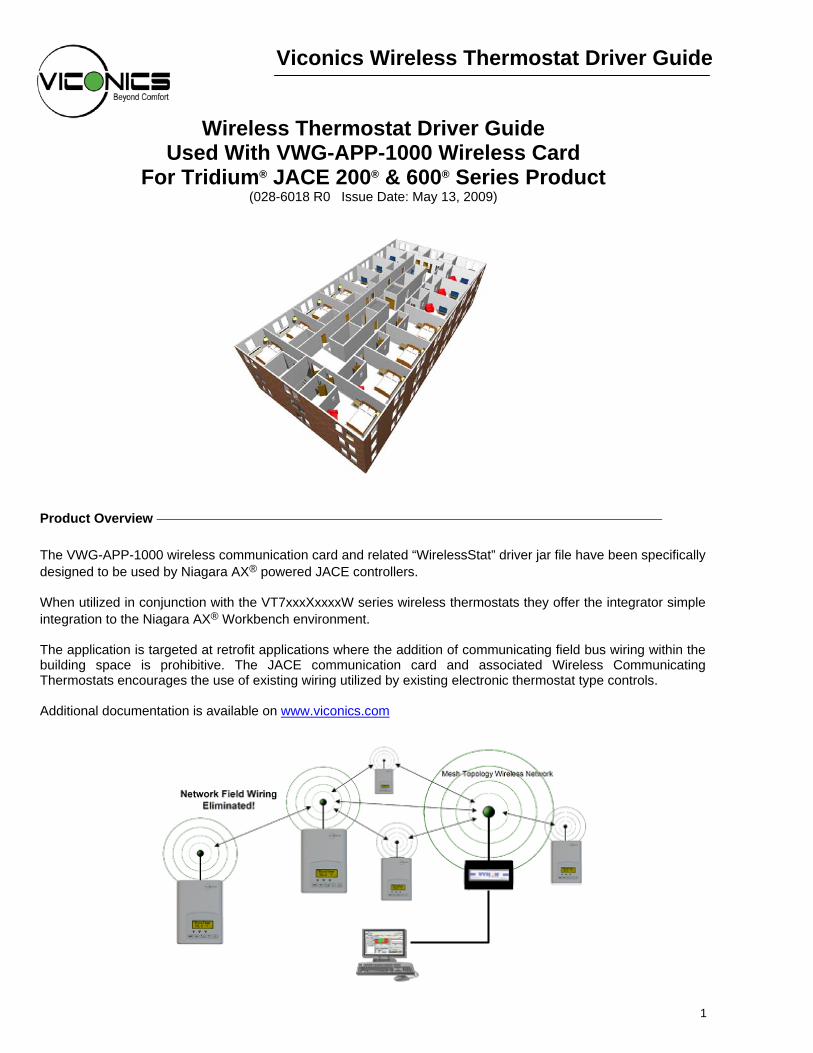
The VWG-APP-1000 wireless communication card and related “WirelessStat” driver jar file have been specifically designed to be used by Niagara AX® powered JACE controllers. When utilized in conjunction with the VT7xxxXxxxxW series wireless thermostats they offer the integrator simple integration to the Niagara AX® Workbench environment. The application is targeted at retrofit applications where the addition of communicating field bus wiring within the building space is prohibitive. The JACE communication card and associated Wireless Communicating Thermostats encourages the use of existing wiring utilized by existing electronic thermostat type controls. Additional documentation is available on www.viconics.com

2
Trademarks Niagara, Niagara AX is a registered trademark of Tridium, Inc. LON, LonWorks and LonTalk are registered trademarks of Echelon Corporation BACnet is a registered trademark of ASHRAE Disclaimers
NO WARRANTY. Viconics, Inc. ( herein after referred to as “Viconics” ) makes no warranty as to the accuracy of or use of this technical documentation. Any use of the technical documentation or the information contained therein is solely at the risk of the user. Documentation may include technical or other inaccuracies or typographical errors. Viconics reserves the right to make changes to this document without prior notice, and the reader should in all cases consult Viconics to determine whether any such changes have been made. The information in this publication does not represent a commitment on the part of Viconics. Viconics shall not be liable for incidental or consequential damages resulting from the furnishing, performance, or use of this material. This guide contains links and references to third-party websites that are not under the control of Viconics, and Viconics is not responsible for the content of any reference material or linked websites. If you access a third party website mentioned in this guide, then you do so at your own risk. Viconics provides these links only as a convenience, and the inclusion of the link does not imply that Viconics endorses or accepts any responsibility for the content on those third-party sites. Electronic controls are static sensitive devices. Discharge yourself properly before manipulation and installing the Viconics wireless gateway. All Viconics wireless gateways and related wireless thermostats are to be used only as operating controls. Whenever a control failure could lead to personal injury and/or loss of property, it becomes the responsibility of the user to add safety devices and/or alarm system to protect against such catastrophic failures. All VT7000 series wireless thermostats and associated components have been rigorously tested to ensure reliable operation in most building applications using the latest 2.4 ZigBee technologies. Viconics cannot guarantee against potential network interference should additional wireless systems be deployed sharing close proximity. Best practices covered in this manual and all related Viconics documents should be considered as a guide to apply Viconics Wireless Network devices only. The instructions included in this manual are based upon Viconics in house testing and should be referred to as a guide only. Viconics Inc. may not be held liable for continued reliable, or robust operation of any and all wireless based devices. Although Viconics has taken many precautions in assuring the robustness of the VT7000 series wireless thermostat product line and associated network access point (JACE’s with wireless option card) Please note; future application of additional wireless devices utilizing the same or similar channels and / or frequencies may degrade performance of overall system and / or reliability. Non-approved modifications or changes made to the communication card, the wireless thermostat driver or wireless thermostats may void the FCC compliance of the wireless card and wireless thermostats. Ferrites supplied with the power supply and VWG MUST be installed according to instructions. Failure to do so may void the FCC compliance of the wireless card and wireless thermostats. THIS DEVICE COMPLIES WITH PART 15 OF THE FCC RULES. OPERATION IS SUBJECT TO THE FOLLOWING TWO CONDITIONS: (1) THIS DEVICE MAY NOT CAUSE HARMFUL INTERFERENCE, AND (2) THIS DEVICE MUST ACCEPT ANY INTERFERENCE RECEIVED, INCLUDING INTERFERENCE THAT MAY CAUSE UNDESIRED OPERATION.
3
About Viconics Wireless Mesh Networks
The Viconics wireless card ( VWG-APP-1000 ) and related wireless thermostat family (VT7xxxXxxxxW) networkable devices operate using ZigBee/IEEE 802.15.4 physical layer for communication. General characteristics of the wireless physical communication layer are:
• Uses a wireless physical layer of 2.4GHz with a data rates of 250 kbps • Yields high throughput and low latency • Automatic multiple topologies configuration: star, peer-to-peer, mesh • Fully handshake protocol for transfer reliability • Range: 30 feet / 10M typical (up to 100 feet / 30 M based on environment)
IEEE 802.15.4 along with ZigBee Networks and Application Support Layer provide: • Low cost installation deployment • Ease of implementation • Reliable data transfer • Short range operation • Very low power consumption • Appropriate levels of security
The JACE with the wireless communication card acts as network coordinator device for the IEEE 802.15.4/ZigBee network used with the Viconics wireless thermostats. Many network specific features of the IEEE 802.15.4 standard are not covered in detail in this paper. However, these are necessary for the efficient operation of a ZigBee network. These features of the network physical layer include receiver energy detection, link quality indication and clear channel assessment. Both contention-based and contention-free channel access methods are supported with a maximum packet size of 128 bytes, which includes a variable payload up to 104 bytes. Also employed are 64-bit IEEE and 16-bit short addressing, supporting over 65,000 nodes per network. All those properties of the physical layer are used and employed by the Viconics mesh network but are hidden to the installed / user for ease of configuration and commissioning of the network database.
A “recommended” typical maximum of 30 networkable thermostats can be supported by a single JACE2. Database creation and configuration is easily made using the Workbench environment.
The theoretical maximum of number of thermostats supported by a single Jace is dependent on the resources available for the WirelessStatNetwork driver Jar file and the extent of integration added to the station itself. When additional functions and services are added to the station, the available resources for the driver will be less. Once you have configured the station for the wireless network and all other features (graphics, services, histories, alarms, etc.), you should monitor the resources so that they do not exceed the recommended limits for each specific platform.
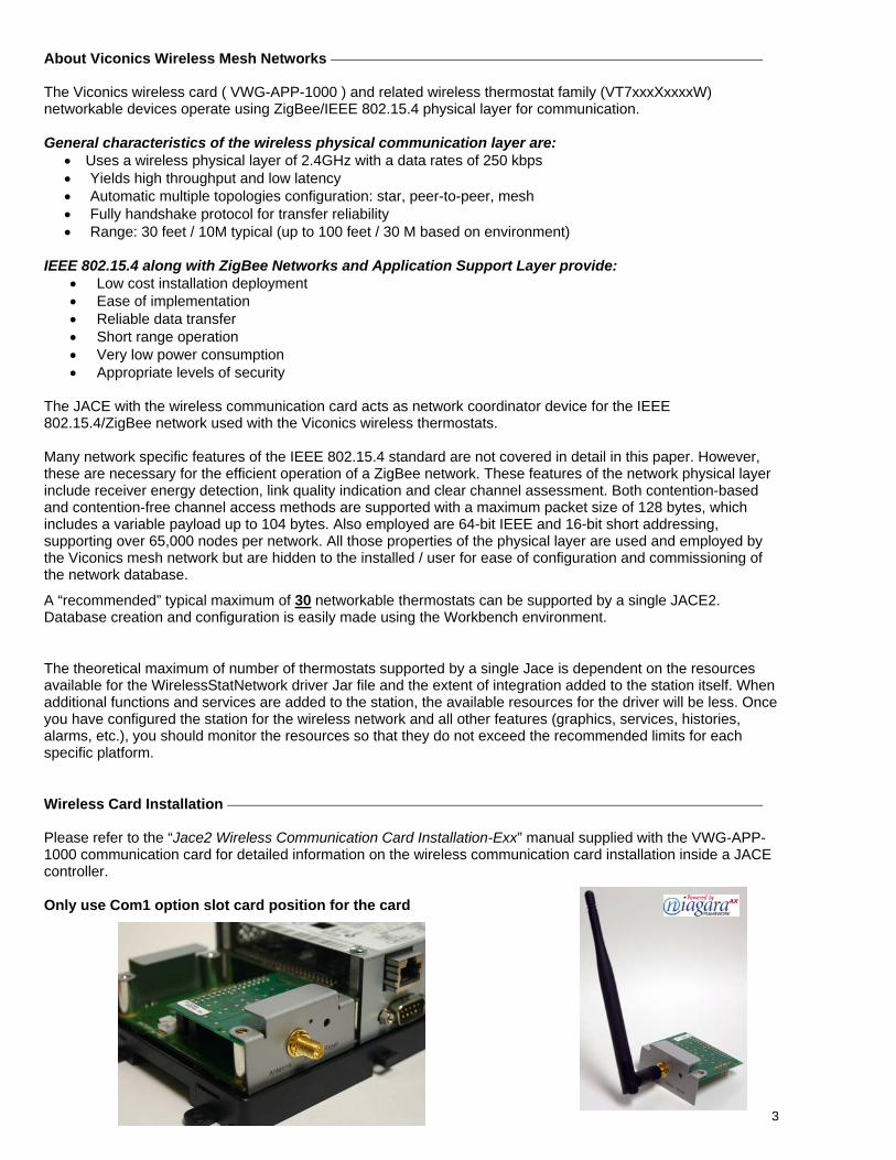
Wireless Card Installation Please refer to the “Jace2 Wireless Communication Card Installation-Exx” manual supplied with the VWG-APP-1000 communication card for detailed information on the wireless communication card installation inside a JACE controller. Only use Com1 option slot card position for the card
4
Basic Initial Design And Deployment Consideration
Proper design considerations need to be addressed prior to any installation of a JACE with a Viconics wireless communication card and related wireless thermostats.
1. To properly avoid network interference with 802.11 Wi-Fi devices in the 2.4GHz spectrum range, Viconics recommends the use of 802.15.4 channels 25 and 26 only. 802.11 Wi-Fi transmissions overlap and may interfere with other channel selection allowed by 802.15.4 ( Channels 11 to 24 )
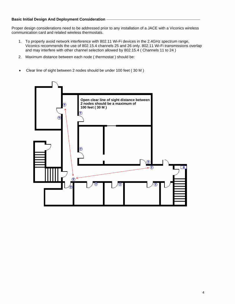
2. Maximum distance between each node ( thermostat ) should be:
• Clear line of sight between 2 nodes should be under 100 feet ( 30 M )
Maximum 100 feet ( 30 M ) between 2 thermostat nodes
Open clear line of sight distance between2 nodes should be a maximum of 100 feet ( 30 M )
5
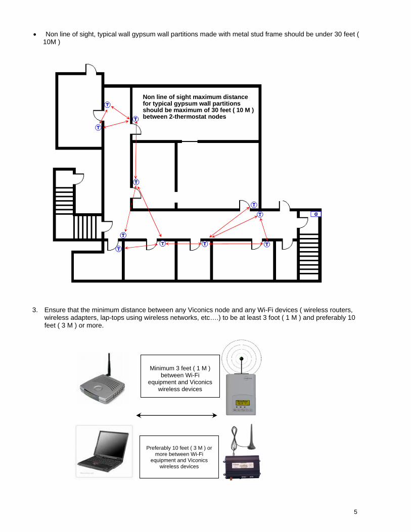
• Non line of sight, typical wall gypsum wall partitions made with metal stud frame should be under 30 feet (
10M )
3. Ensure that the minimum distance between any Viconics node and any Wi-Fi devices ( wireless routers, wireless adapters, lap-tops using wireless networks, etc….) to be at least 3 foot ( 1 M ) and preferably 10 feet ( 3 M ) or more.
Maximum 30 feet ( 10 M ) between 2-thermostat nodes
Minimum 3 feet ( 1 M )
between Wi-Fi equipment and Viconics
wireless devices
Preferably 10 feet ( 3 M ) or
more between Wi-Fi equipment and Viconics
wireless devices
Non line of sight maximum distancefor typical gypsum wall partitionsshould be maximum of 30 feet ( 10 M )between 2-thermostat nodes

6
4. Ensure that at least one thermostat is within 30 feet of the VWG for every cluster of 10 thermostats
installed. 5. Always try to locate if possible the VWG near the center of all associated wireless thermostats. 6. Always try to locate the VWG near on in line of sigh to as many wireless thermostats as possible. 7. Try to avoid metal, brick walls or concrete obstructions between wireless devices as much as possible. 8. Make sure the antenna on the VWG is always perpendicular to the floor. 9. Avoid placing VWG and thermostats near metal or enclosed in metal boxes. If the VWG needs to be
installed inside a metal cabinet, use the remote antenna accessory. Ex. For a recommended maximum of 30 wireless thermostats total per JACE, a minimum of 3 of them should be within 30 feet ( 9 M ) of the VWG range.
30 feet ( 9 M )
At least 1 Viconics thermostat node to be within 30 feet ( 9 M ) of theVWG for every other 10 thermostatinstalledv
7
JACE And Wireless Communication Card Configuration Initial Configuration Note: The following instructions assume you are familiar with the AX workbench environment and its related functions
• Install the wireless communication card as stipulated by the instructions provided with the wireless card
• Copy the “WirelessStatNetwork” jar file to your local AX Workbench module folder
• Using the Software Manager, add the “WirelessStat” jar file to the target JACE with the wireless communication card already installed
• Re-boot both the local AX Workbench interface and the JACE itself to properly load the “WirelessStatNetwork” jar module
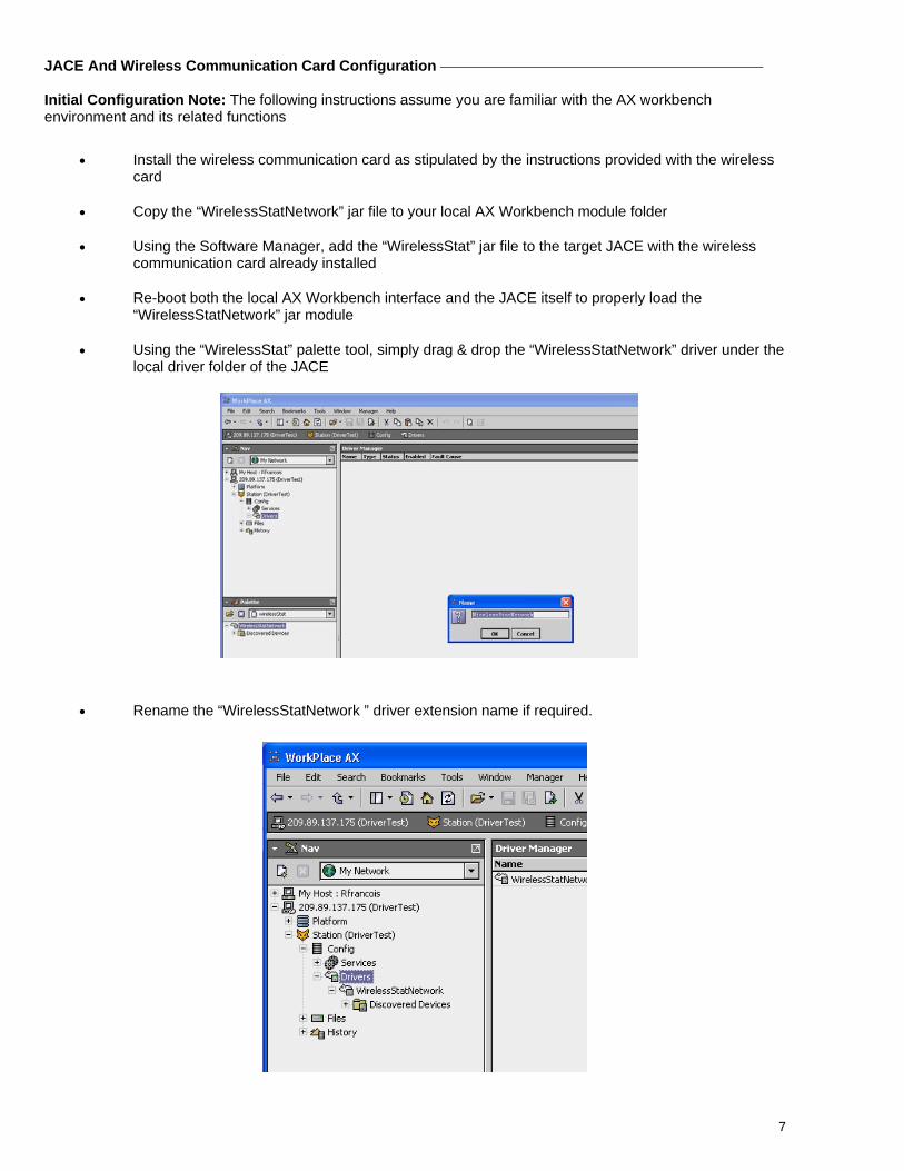
• Using the “WirelessStat” palette tool, simply drag & drop the “WirelessStatNetwork” driver under the local driver folder of the JACE
• Rename the “WirelessStatNetwork ” driver extension name if required.
8
• Rename the “WirelessStatNetwork ” driver extension name if required.
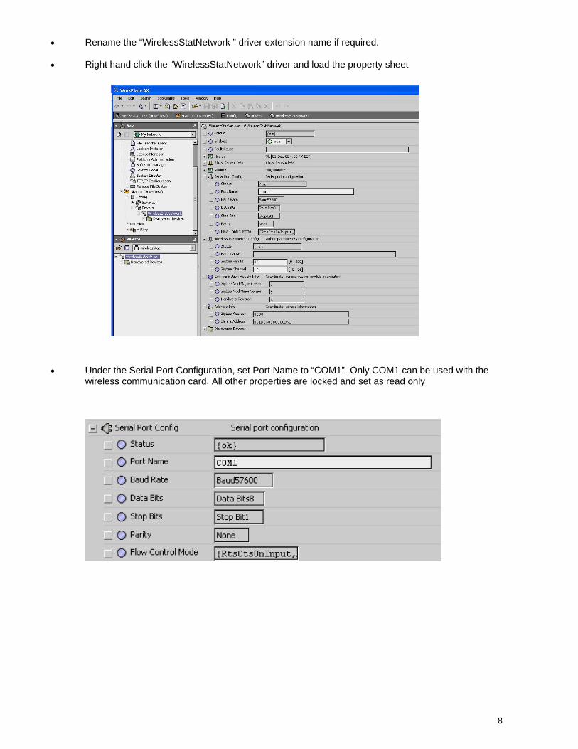
• Right hand click the “WirelessStatNetwork” driver and load the property sheet
• Under the Serial Port Configuration, set Port Name to “COM1”. Only COM1 can be used with the wireless communication card. All other properties are locked and set as read only
9
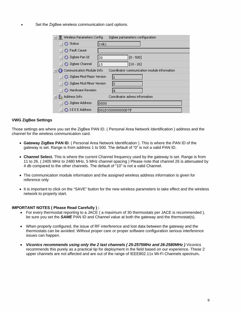
• Set the ZigBee wireless communication card options.
VWG ZigBee Settings Those settings are where you set the ZigBee PAN ID. ( Personal Area Network Identification ) address and the channel for the wireless communication card.
• Gateway ZigBee PAN ID. ( Personal Area Network Identification ). This is where the PAN ID of the gateway is set. Range is from address 1 to 500. The default of “0” is not a valid PAN ID.
• Channel Select. This is where the current Channel frequency used by the gateway is set. Range is from
11 to 26. ( 2405 MHz to 2480 MHz, 5 MHz channel spacing ) Please note that channel 26 is attenuated by 4 db compared to the other channels. The default of “10” is not a valid Channel.
• The communication module information and the assigned wireless address information is given for
reference only • It is important to click on the “SAVE” button for the new wireless parameters to take effect and the wireless
network to properly start.
IMPORTANT NOTES ( Please Read Carefully ) : • For every thermostat reporting to a JACE ( a maximum of 30 thermostats per JACE is recommended ),
be sure you set the SAME PAN ID and Channel value at both the gateway and the thermostat(s).
• When properly configured, the issue of RF interference and lost data between the gateway and the thermostats can be avoided. Without proper care or proper software configuration serious interference issues can happen.
• Viconics recommends using only the 2 last channels ( 25-2575MHz and 26-2580MHz ) Viconics recommends this purely as a practical tip for deployment in the field based on our experience. These 2 upper channels are not affected and are out of the range of IEEE802.11x Wi-Fi Channels spectrum.
10
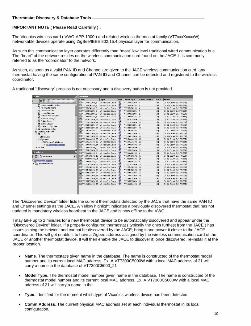
Thermostat Discovery & Database Tools IMPORTANT NOTE ( Please Read Carefully ) : The Viconics wireless card ( VWG-APP-1000 ) and related wireless thermostat family (VT7xxxXxxxxW) networkable devices operate using ZigBee/IEEE 802.15.4 physical layer for communication. As such this communication layer operates differently than “most” low level traditional wired communication bus. The “heart” of the network resides on the wireless communication card found on the JACE. It is commonly referred to as the “coordinator” to the network. As such, as soon as a valid PAN ID and Channel are given to the JACE wireless communication card, any thermostat having the same configuration of PAN ID and Channel can be detected and registered to the wireless coordinator. A traditional “discovery” process is not necessary and a discovery button is not provided.
The “Discovered Device” folder lists the current thermostats detected by the JACE that have the same PAN ID and Channel settings as the JACE. A Yellow highlight indicates a previously discovered thermostat that has not updated is mandatory wireless heartbeat to the JACE and is now offline to the VWG. I may take up to 2 minutes for a new thermostat device to be automatically discovered and appear under the “Discovered Device” folder. If a properly configured thermostat ( typically the ones furthest from the JACE ) has issues joining the network and cannot be discovered by the JACE; bring it and power it closer to the JACE coordinator. This will get enable it to have a Zigbee address assigned by the wireless communication card of the JACE or another thermostat device. It will then enable the JACE to discover it; once discovered, re-install it at the proper location.
• Name. The thermostat’s given name in the database. The name is constructed of the thermostat model number and its current local MAC address. Ex. A VT7300C5000W with a local MAC address of 21 will carry a name in the database of VT7300C5000_21
• Model Type. The thermostat model number given name in the database. The name is constructed of the
thermostat model number and its current local MAC address. Ex. A VT7300C5000W with a local MAC address of 21 will carry a name in the
• Type. Identified for the moment which type of Viconics wireless device has been detected • Comm Address. The current physical MAC address set at each individual thermostat in its local
configuration.
11
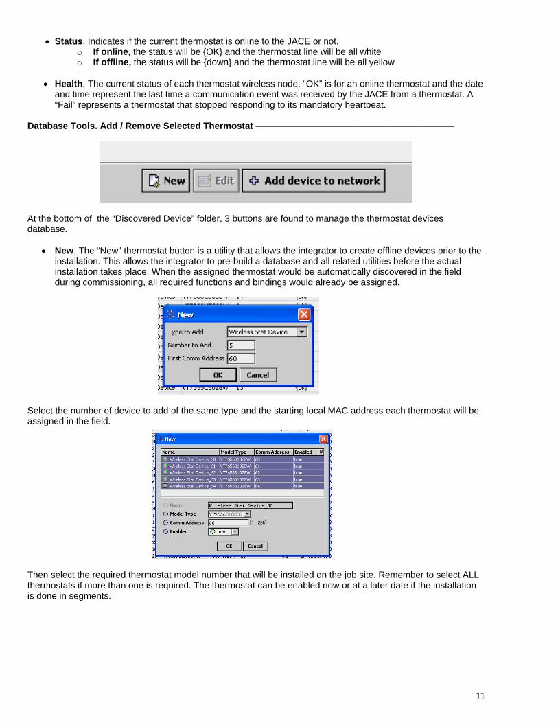
• Status. Indicates if the current thermostat is online to the JACE or not. o If online, the status will be {OK} and the thermostat line will be all white o If offline, the status will be {down} and the thermostat line will be all yellow
• Health. The current status of each thermostat wireless node. “OK” is for an online thermostat and the date
and time represent the last time a communication event was received by the JACE from a thermostat. A “Fail” represents a thermostat that stopped responding to its mandatory heartbeat.
Database Tools. Add / Remove Selected Thermostat
At the bottom of the “Discovered Device” folder, 3 buttons are found to manage the thermostat devices database.
• New. The “New” thermostat button is a utility that allows the integrator to create offline devices prior to the installation. This allows the integrator to pre-build a database and all related utilities before the actual installation takes place. When the assigned thermostat would be automatically discovered in the field during commissioning, all required functions and bindings would already be assigned.
Select the number of device to add of the same type and the starting local MAC address each thermostat will be assigned in the field.
Then select the required thermostat model number that will be installed on the job site. Remember to select ALL thermostats if more than one is required. The thermostat can be enabled now or at a later date if the installation is done in segments.
12
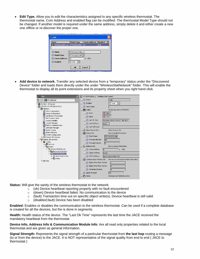
• Edit Type. Allow you to edit the characteristics assigned to any specific wireless thermostat. The
thermostat name, Com Address and enabled flag can be modified. The thermostat Model Type should not be changed. If another model is required under the same address, simply delete it and either create a new one offline or re-discover the proper one.
• Add device to network. Transfer any selected device from a “temporary” status under the “Discovered Device” folder and loads them directly under the under “WirelessStatNetwork” folder. This will enable the thermostat to display all its point extensions and its property sheet when you right hand click.
Status: Will give the sanity of the wireless thermostat to the network
o (ok) Device heartbeat reporting properly with no fault encountered o (down) Device heartbeat failed. No communication to the device o (fault) Transaction time out on specific object write(s). Device heartbeat is still valid o (disabled,fault) Device has been disabled
Enabled: Enables or disables the communication to the wireless thermostat. Can be used if a complete database is created for all the devices, but the is done in segments.
Health: Health status of the device. The “Last Ok Time” represents the last time the JACE received the mandatory heartbeat from the thermostat
Device Info, Address Info & Communication Module Info: Are all read only properties related to the local thermostat and are given as general information.
Signal Strength: Represents the signal strength of a particular thermostat from the last hop routing a message (to or from the device) to the JACE. It is NOT representative of the signal quality from end to end ( JACE to thermostat )
13
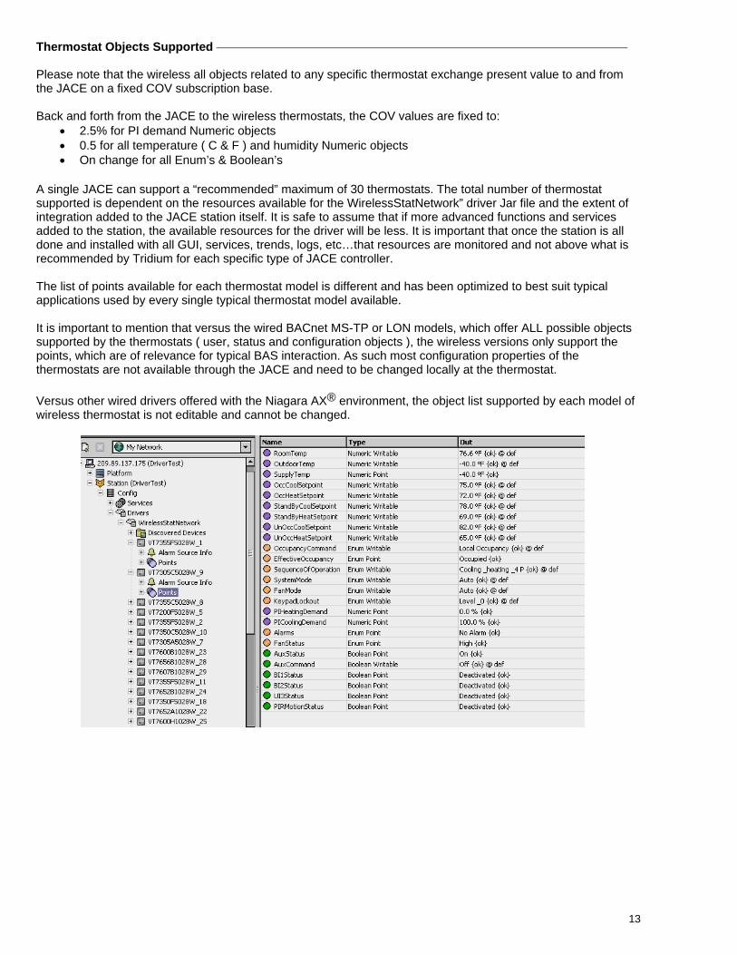
Thermostat Objects Supported Please note that the wireless all objects related to any specific thermostat exchange present value to and from the JACE on a fixed COV subscription base. Back and forth from the JACE to the wireless thermostats, the COV values are fixed to:
• 2.5% for PI demand Numeric objects • 0.5 for all temperature ( C & F ) and humidity Numeric objects • On change for all Enum’s & Boolean’s
A single JACE can support a “recommended” maximum of 30 thermostats. The total number of thermostat supported is dependent on the resources available for the WirelessStatNetwork” driver Jar file and the extent of integration added to the JACE station itself. It is safe to assume that if more advanced functions and services added to the station, the available resources for the driver will be less. It is important that once the station is all done and installed with all GUI, services, trends, logs, etc…that resources are monitored and not above what is recommended by Tridium for each specific type of JACE controller. The list of points available for each thermostat model is different and has been optimized to best suit typical applications used by every single typical thermostat model available. It is important to mention that versus the wired BACnet MS-TP or LON models, which offer ALL possible objects supported by the thermostats ( user, status and configuration objects ), the wireless versions only support the points, which are of relevance for typical BAS interaction. As such most configuration properties of the thermostats are not available through the JACE and need to be changed locally at the thermostat. Versus other wired drivers offered with the Niagara AX® environment, the object list supported by each model of wireless thermostat is not editable and cannot be changed.
14
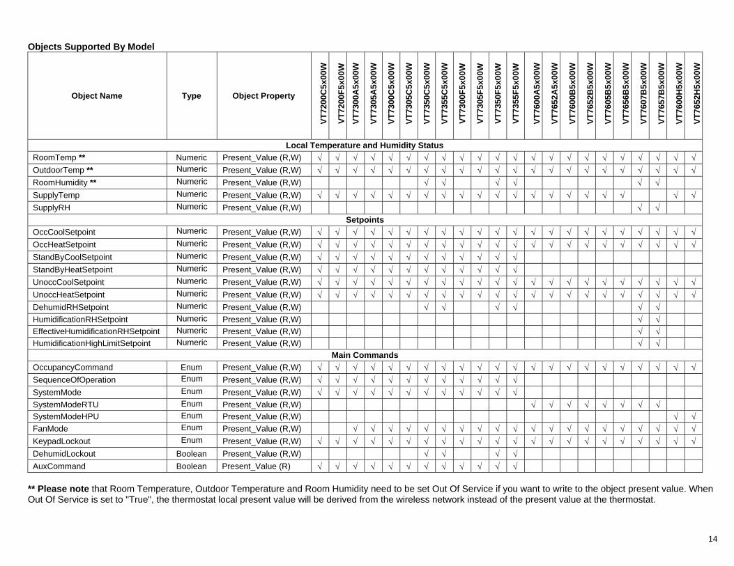
Objects Supported By Model
Object Name Type Object Property
VT72
00C
5x00
W
VT72
00F5
x00W
VT73
00A
5x00
W
VT73
05A
5x00
W
VT73
00C
5x00
W
VT73
05C
5x00
W
VT73
50C
5x00
W
VT73
55C
5x00
W
VT73
00F5
x00W
VT73
05F5
x00W
VT73
50F5
x00W
VT73
55F5
x00W
VT76
00A
5x00
W
VT76
52A
5x00
W
VT76
00B
5x00
W
VT76
52B
5x00
W
VT76
05B
5x00
W
VT76
56B
5x00
W
VT76
07B
5x00
W
VT76
57B
5x00
W
VT76
00H
5x00
W
VT76
52H
5x00
W
Local Temperature and Humidity Status RoomTemp ** Numeric Present_Value (R,W) √ √ √ √ √ √ √ √ √ √ √ √ √ √ √ √ √ √ √ √ √ √ OutdoorTemp ** Numeric Present_Value (R,W) √ √ √ √ √ √ √ √ √ √ √ √ √ √ √ √ √ √ √ √ √ √ RoomHumidity ** Numeric Present_Value (R,W) √ √ √ √ √ √ SupplyTemp Numeric Present_Value (R,W) √ √ √ √ √ √ √ √ √ √ √ √ √ √ √ √ √ √ √ √ SupplyRH Numeric Present_Value (R,W) √ √
Setpoints OccCoolSetpoint Numeric Present_Value (R,W) √ √ √ √ √ √ √ √ √ √ √ √ √ √ √ √ √ √ √ √ √ √ OccHeatSetpoint Numeric Present_Value (R,W) √ √ √ √ √ √ √ √ √ √ √ √ √ √ √ √ √ √ √ √ √ √ StandByCoolSetpoint Numeric Present_Value (R,W) √ √ √ √ √ √ √ √ √ √ √ √ StandByHeatSetpoint Numeric Present_Value (R,W) √ √ √ √ √ √ √ √ √ √ √ √ UnoccCoolSetpoint Numeric Present_Value (R,W) √ √ √ √ √ √ √ √ √ √ √ √ √ √ √ √ √ √ √ √ √ √ UnoccHeatSetpoint Numeric Present_Value (R,W) √ √ √ √ √ √ √ √ √ √ √ √ √ √ √ √ √ √ √ √ √ √ DehumidRHSetpoint Numeric Present_Value (R,W) √ √ √ √ √ √ HumidificationRHSetpoint Numeric Present_Value (R,W) √ √ EffectiveHumidificationRHSetpoint Numeric Present_Value (R,W) √ √ HumidificationHighLimitSetpoint Numeric Present_Value (R,W) √ √
Main Commands OccupancyCommand Enum Present_Value (R,W) √ √ √ √ √ √ √ √ √ √ √ √ √ √ √ √ √ √ √ √ √ √ SequenceOfOperation Enum Present_Value (R,W) √ √ √ √ √ √ √ √ √ √ √ √ SystemMode Enum Present_Value (R,W) √ √ √ √ √ √ √ √ √ √ √ √ SystemModeRTU Enum Present_Value (R,W) √ √ √ √ √ √ √ √ SystemModeHPU Enum Present_Value (R,W) √ √ FanMode Enum Present_Value (R,W) √ √ √ √ √ √ √ √ √ √ √ √ √ √ √ √ √ √ √ √ KeypadLockout Enum Present_Value (R,W) √ √ √ √ √ √ √ √ √ √ √ √ √ √ √ √ √ √ √ √ √ √ DehumidLockout Boolean Present_Value (R,W) √ √ √ √ AuxCommand Boolean Present_Value (R) √ √ √ √ √ √ √ √ √ √ √ √
** Please note that Room Temperature, Outdoor Temperature and Room Humidity need to be set Out Of Service if you want to write to the object present value. When Out Of Service is set to "True", the thermostat local present value will be derived from the wireless network instead of the present value at the thermostat.
15
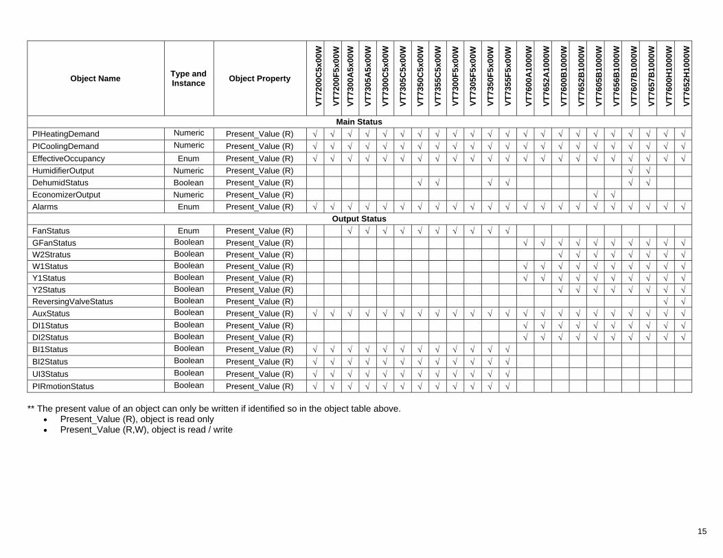
Object Name Type and Instance Object Property
VT72
00C
5x00
W
VT72
00F5
x00W
VT73
00A
5x00
W
VT73
05A
5x00
W
VT73
00C
5x00
W
VT73
05C
5x00
W
VT73
50C
5x00
W
VT73
55C
5x00
W
VT73
00F5
x00W
VT73
05F5
x00W
VT73
50F5
x00W
VT73
55F5
x00W
VT76
00A
1000
W
VT76
52A
1000
W
VT76
00B
1000
W
VT76
52B
1000
W
VT76
05B
1000
W
VT76
56B
1000
W
VT76
07B
1000
W
VT76
57B
1000
W
VT76
00H
1000
W
VT76
52H
1000
W
Main Status PIHeatingDemand Numeric Present_Value (R) √ √ √ √ √ √ √ √ √ √ √ √ √ √ √ √ √ √ √ √ √ √ PICoolingDemand Numeric Present_Value (R) √ √ √ √ √ √ √ √ √ √ √ √ √ √ √ √ √ √ √ √ √ √ EffectiveOccupancy Enum Present_Value (R) √ √ √ √ √ √ √ √ √ √ √ √ √ √ √ √ √ √ √ √ √ √ HumidifierOutput Numeric Present_Value (R) √ √ DehumidStatus Boolean Present_Value (R) √ √ √ √ √ √ EconomizerOutput Numeric Present_Value (R) √ √ Alarms Enum Present_Value (R) √ √ √ √ √ √ √ √ √ √ √ √ √ √ √ √ √ √ √ √ √ √
Output Status FanStatus Enum Present_Value (R) √ √ √ √ √ √ √ √ √ √ GFanStatus Boolean Present_Value (R) √ √ √ √ √ √ √ √ √ √ W2Stratus Boolean Present_Value (R) √ √ √ √ √ √ √ √ W1Status Boolean Present_Value (R) √ √ √ √ √ √ √ √ √ √ Y1Status Boolean Present_Value (R) √ √ √ √ √ √ √ √ √ √ Y2Status Boolean Present_Value (R) √ √ √ √ √ √ √ √ ReversingValveStatus Boolean Present_Value (R) √ √ AuxStatus Boolean Present_Value (R) √ √ √ √ √ √ √ √ √ √ √ √ √ √ √ √ √ √ √ √ √ √ DI1Status Boolean Present_Value (R) √ √ √ √ √ √ √ √ √ √ DI2Status Boolean Present_Value (R) √ √ √ √ √ √ √ √ √ √ BI1Status Boolean Present_Value (R) √ √ √ √ √ √ √ √ √ √ √ √ BI2Status Boolean Present_Value (R) √ √ √ √ √ √ √ √ √ √ √ √ UI3Status Boolean Present_Value (R) √ √ √ √ √ √ √ √ √ √ √ √ PIRmotionStatus Boolean Present_Value (R) √ √ √ √ √ √ √ √ √ √ √ √
** The present value of an object can only be written if identified so in the object table above.
• Present_Value (R), object is read only • Present_Value (R,W), object is read / write
16
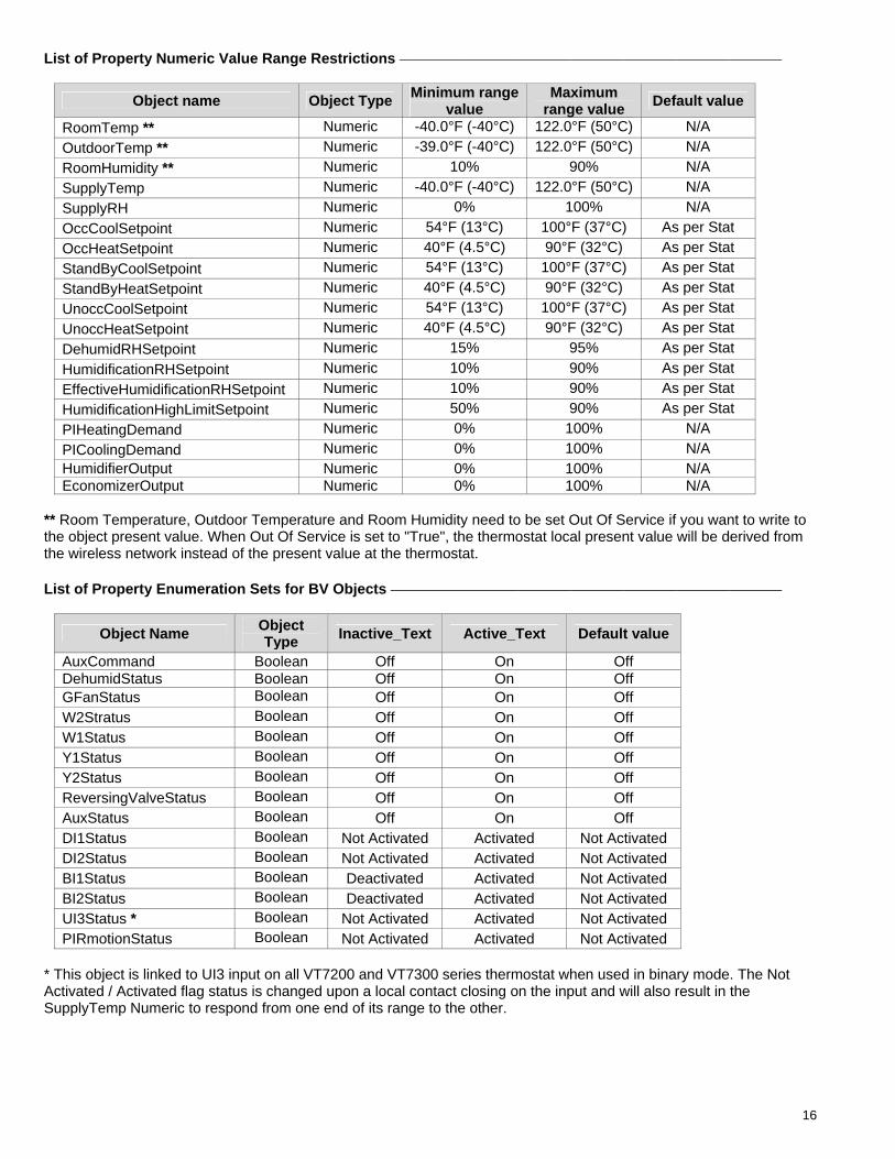
List of Property Numeric Value Range Restrictions
Object name Object Type Minimum range value
Maximum range value Default value
RoomTemp ** Numeric -40.0°F (-40°C) 122.0°F (50°C) N/A OutdoorTemp ** Numeric -39.0°F (-40°C) 122.0°F (50°C) N/A RoomHumidity ** Numeric 10% 90% N/A SupplyTemp Numeric -40.0°F (-40°C) 122.0°F (50°C) N/A SupplyRH Numeric 0% 100% N/A OccCoolSetpoint Numeric 54°F (13°C) 100°F (37°C) As per Stat OccHeatSetpoint Numeric 40°F (4.5°C) 90°F (32°C) As per Stat StandByCoolSetpoint Numeric 54°F (13°C) 100°F (37°C) As per Stat StandByHeatSetpoint Numeric 40°F (4.5°C) 90°F (32°C) As per Stat UnoccCoolSetpoint Numeric 54°F (13°C) 100°F (37°C) As per Stat UnoccHeatSetpoint Numeric 40°F (4.5°C) 90°F (32°C) As per Stat DehumidRHSetpoint Numeric 15% 95% As per Stat HumidificationRHSetpoint Numeric 10% 90% As per Stat EffectiveHumidificationRHSetpoint Numeric 10% 90% As per Stat HumidificationHighLimitSetpoint Numeric 50% 90% As per Stat PIHeatingDemand Numeric 0% 100% N/A PICoolingDemand Numeric 0% 100% N/A HumidifierOutput Numeric 0% 100% N/A EconomizerOutput Numeric 0% 100% N/A
** Room Temperature, Outdoor Temperature and Room Humidity need to be set Out Of Service if you want to write to the object present value. When Out Of Service is set to "True", the thermostat local present value will be derived from the wireless network instead of the present value at the thermostat.
List of Property Enumeration Sets for BV Objects
Object Name Object Type Inactive_Text Active_Text Default value
AuxCommand Boolean Off On Off DehumidStatus Boolean Off On Off GFanStatus Boolean Off On Off W2Stratus Boolean Off On Off W1Status Boolean Off On Off Y1Status Boolean Off On Off Y2Status Boolean Off On Off ReversingValveStatus Boolean Off On Off AuxStatus Boolean Off On Off DI1Status Boolean Not Activated Activated Not Activated DI2Status Boolean Not Activated Activated Not Activated BI1Status Boolean Deactivated Activated Not Activated BI2Status Boolean Deactivated Activated Not Activated UI3Status * Boolean Not Activated Activated Not Activated PIRmotionStatus Boolean Not Activated Activated Not Activated
* This object is linked to UI3 input on all VT7200 and VT7300 series thermostat when used in binary mode. The Not Activated / Activated flag status is changed upon a local contact closing on the input and will also result in the SupplyTemp Numeric to respond from one end of its range to the other.
17
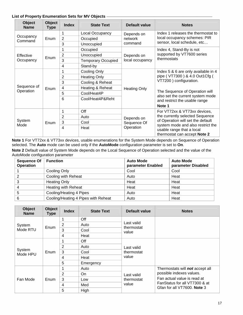
List of Property Enumeration Sets for MV Objects
Object Name
Object Type Index State Text Default value Notes
1 Local Occupancy 2 Occupied Occupancy
Command Enum 3 Unoccupied
Depends on network command
Index 1 releases the thermostat to local occupancy schemes: PIR sensor, local schedule, etc…
1 Occupied 2 Unoccupied 3 Temporary Occupied
Effective Occupancy Enum
4 Stand-by
Depends on local occupancy
Index 4, Stand-By is not supported by VT7600 series thermostats
1 Cooling Only 2 Heating Only 3 Cooling & Reheat 4 Heating & Reheat 5 Cool/Heat4P
Sequence of Operation Enum
6 Cool/Heat4P&Reht
Heating Only
Index 5 & 6 are only available in 4 pipe ( VT7300 ) & 4.0 Out1Cfg ( VT7200 ) configuration. The Sequence of Operation will also set the current system mode and restrict the usable range Note 1
1 Off 2 Auto 3 Cool System
Mode Enum 4 Heat
Depends on Sequence Of Operation
For VT72xx & VT73xx devices, the currently selected Sequence of Operation will set the default system mode and also restrict the usable range that a local thermostat can accept Note 2
Note 1 For VT72xx & VT73xx devices, usable enumerations for the System Mode depends on Sequence of Operation selected. The Auto mode can be used only if the AutoMode configuration parameter is set to On.
Note 2 Default value of System Mode depends on the Local Sequence of Operation selected and the value of the AutoMode configuration parameter
Sequence Of Operation
Function Auto Mode parameter Enabled
Auto Mode parameter Disabled
1 Cooling Only Cool Cool 2 Cooling with Reheat Auto Heat 3 Heating Only Heat Heat 4 Heating with Reheat Heat Heat 5 Cooling/Heating 4 Pipes Auto Heat 6 Cooling/Heating 4 Pipes with Reheat Auto Heat
Object Name
Object Type Index State Text Default value Notes
1 Off 2 Auto 3 Cool
System Mode RTU Enum
4 Heat
Last valid thermostat value
1 Off 2 Auto 3 Cool 4 Heat
System Mode HPU Enum
5 Emergency
Last valid thermostat value
1 Auto 2 On 3 Low 4 Med
Fan Mode Enum
5 High
Last valid thermostat value
Thermostats will not accept all possible indexes values. Fan actual value is read at FanStatus for all VT7300 & at Gfan for all VT7600. Note 3
18
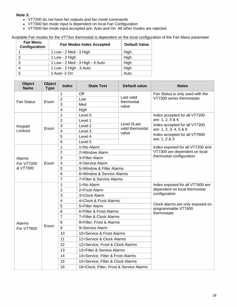
Note 3: • VT7200 do not have fan outputs and fan mode commands • VT7300 fan mode input is dependent on local Fan Configuration • VT7600 fan mode input accepted are: Auto and On. All other modes are rejected.
Available Fan modes for the VT73xx thermostat is dependent on the local configuration of the Fan Menu parameter
Fan Menu Configuration Fan Modes Index Accepted Default Value
1 1 Low - 2 Med - 3 High High 2 1 Low - 2 High High 3 1 Low - 2 Med - 3 High - 4 Auto High 4 1 Low - 2 High - 3 Auto High 5 1 Auto -2 On Auto
Object Name
Object Type Index State Text Default value Notes
1 Off 2 Low 3 Med
Fan Status Enum
4 High
Last valid thermostat value
Fan Status is only used with the VT7300 series thermostats
1 Level 0 2 Level 1 3 Level 2 4 Level 3 5 Level 4
Keypad Lockout Enum
6 Level 5
Level 0Last valid thermostat value
Index accepted for all VT7200 are: 1, 2, 5 & 6 Index accepted for all VT7300 are: 1, 2, 3, 4, 5 & 6 Index accepted for all VT7600 are: 1, 2 & 3
1 1=No Alarm 2 2=Window Alarm 3 3=Filter Alarm 4 4=Service Alarm 5 5=Window & Filter Alarms 6 6=Window & Service Alarms
Alarms For VT7200 & VT7300
Enum
7 7=Filter & Service Alarms
Index exposed for all VT7200 and VT7300 are dependent on local thermostat configuration
1 1=No Alarm 2 2=Frost Alarm 3 3=Clock Alarm 4 4=Clock & Frost Alarms 5 5=Filter Alarm 6 6=Filter & Frost Alarms 7 7=Filter & Clock Alarms 8 8=Filter, Frost & Alarms 9 9=Service Alarm 10 10=Service & Frost Alarms 11 11=Service & Clock Alarms 12 12=Service, Frost & Clock Alarms 13 13=Filter & Service Alarms 14 14=Service, Filter & Frost Alarms 15 15=Service, Filter & Clock Alarms
Alarms For VT7600
Enum
16 16=Clock, Filter, Frost & Service Alarms
Index exposed for all VT7600 are dependent on local thermostat configuration Clock alarms are only exposed on programmable VT7600 thermostats
19
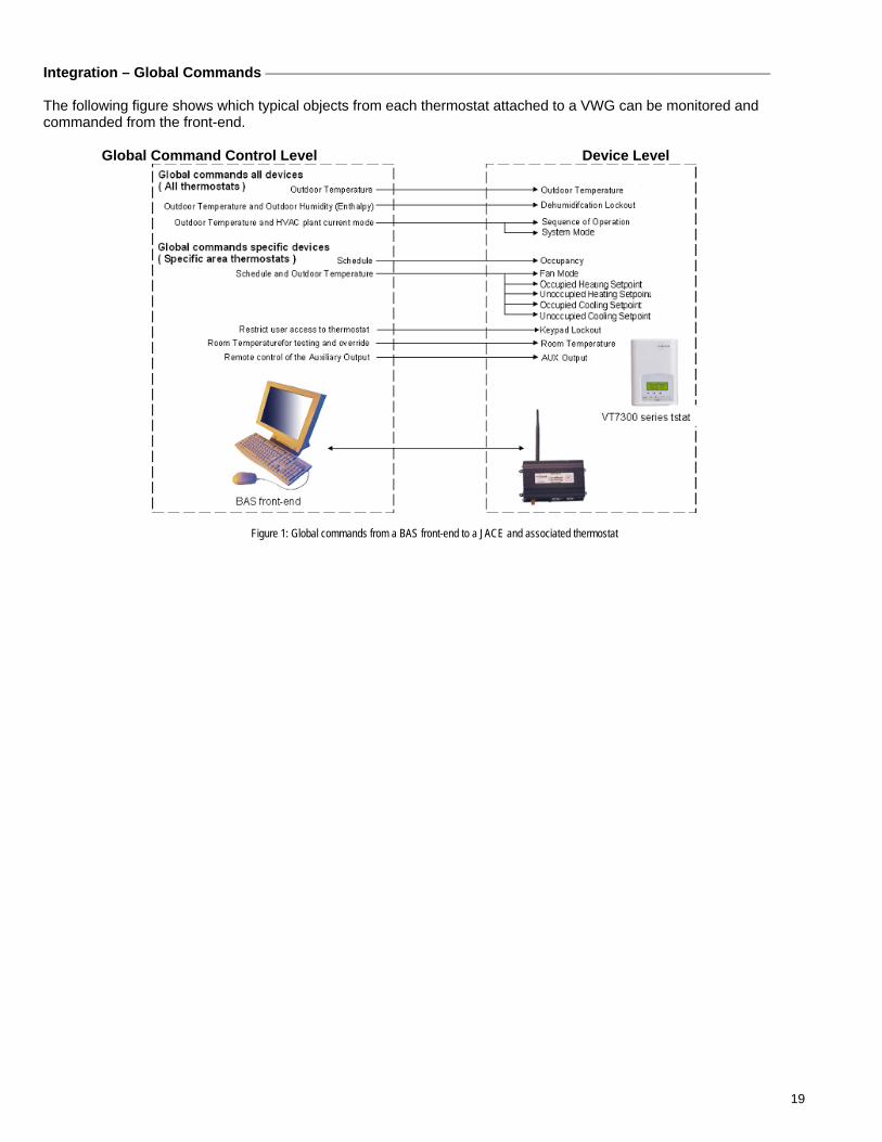
Integration – Global Commands The following figure shows which typical objects from each thermostat attached to a VWG can be monitored and commanded from the front-end.
Global Command Control Level Device Level
Figure 1: Global commands from a BAS front-end to a JACE and associated thermostat
20
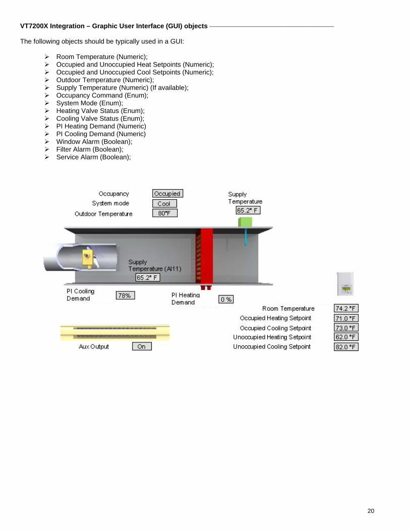
VT7200X Integration – Graphic User Interface (GUI) objects The following objects should be typically used in a GUI:
Room Temperature (Numeric); Occupied and Unoccupied Heat Setpoints (Numeric); Occupied and Unoccupied Cool Setpoints (Numeric); Outdoor Temperature (Numeric); Supply Temperature (Numeric) (If available); Occupancy Command (Enum); System Mode (Enum); Heating Valve Status (Enum); Cooling Valve Status (Enum); PI Heating Demand (Numeric) PI Cooling Demand (Numeric) Window Alarm (Boolean); Filter Alarm (Boolean); Service Alarm (Boolean);
21
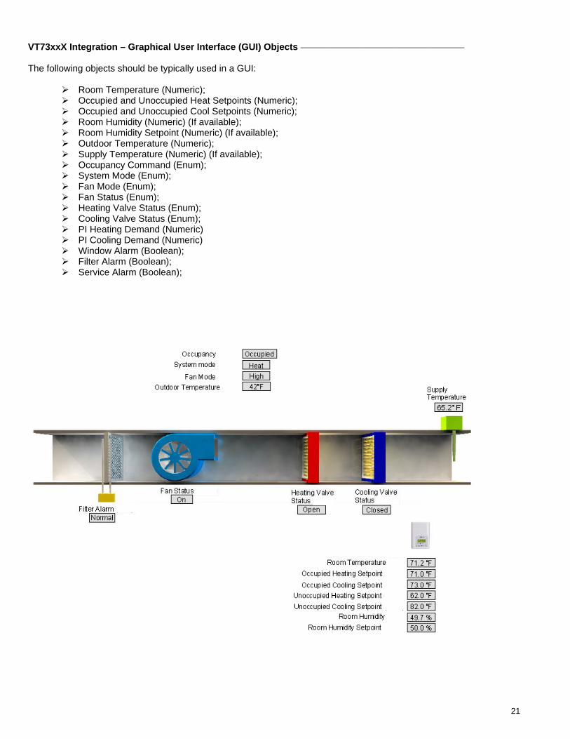
VT73xxX Integration – Graphical User Interface (GUI) Objects The following objects should be typically used in a GUI:
Room Temperature (Numeric); Occupied and Unoccupied Heat Setpoints (Numeric); Occupied and Unoccupied Cool Setpoints (Numeric); Room Humidity (Numeric) (If available); Room Humidity Setpoint (Numeric) (If available); Outdoor Temperature (Numeric); Supply Temperature (Numeric) (If available); Occupancy Command (Enum); System Mode (Enum); Fan Mode (Enum); Fan Status (Enum); Heating Valve Status (Enum); Cooling Valve Status (Enum); PI Heating Demand (Numeric) PI Cooling Demand (Numeric) Window Alarm (Boolean); Filter Alarm (Boolean); Service Alarm (Boolean);
22
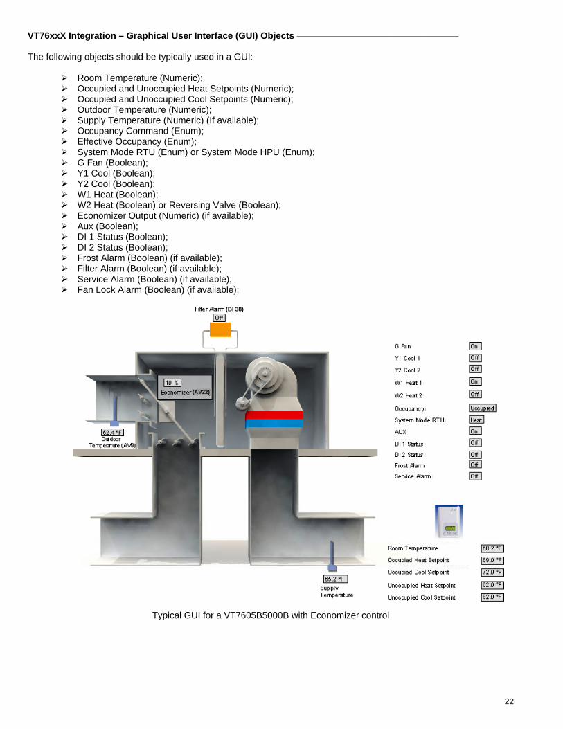
VT76xxX Integration – Graphical User Interface (GUI) Objects The following objects should be typically used in a GUI:
Room Temperature (Numeric); Occupied and Unoccupied Heat Setpoints (Numeric); Occupied and Unoccupied Cool Setpoints (Numeric); Outdoor Temperature (Numeric); Supply Temperature (Numeric) (If available); Occupancy Command (Enum); Effective Occupancy (Enum); System Mode RTU (Enum) or System Mode HPU (Enum); G Fan (Boolean); Y1 Cool (Boolean); Y2 Cool (Boolean); W1 Heat (Boolean); W2 Heat (Boolean) or Reversing Valve (Boolean); Economizer Output (Numeric) (if available); Aux (Boolean); DI 1 Status (Boolean); DI 2 Status (Boolean); Frost Alarm (Boolean) (if available); Filter Alarm (Boolean) (if available); Service Alarm (Boolean) (if available); Fan Lock Alarm (Boolean) (if available);
(BI 38)
(AV22)
(BI 25)
(BI 26)
(BI 27)
(BI 28)
(BI 29)
(MV 12)
(MV 14)
(BI 24)
(BI 31)
(BI 32)
(BI 36)
(BI 39)
(AI 16)
(AV 42)
(AV 43)
(AV 44)
(AV 45)
(AV 45)
(AV 45)
Typical GUI for a VT7605B5000B with Economizer control
23
Tips and Things You Need To Know
Be sure all thermostats connected to a JACE are using the same PAN ID and Channel as the JACE
wireless communication card. Room Temperature, Outdoor Temperature and Room Humidity need to be set Out Of Service if you want
to write to the objects. When Out Of Service is set to True, the local value will be derived from the BACnet network instead of the value at the thermostat.
For VT7200 and VT7300, the currently selected Sequence of Operation Enum limits the System Mode
Enum usable index. A change in the Sequence Of Operation Enum will set the active system mode and also restrict the usable range that a local thermostat can accept.
For VT7300, Fan Mode Enum. Thermostats will not accept all possible index values. VT7300 fan mode
input is dependent on local Fan Configuration parameter. Fan actual current value is read at FanStatus. Each thermostat connected to a wireless network reports to the JACE with an automatic heartbeat for the
local online-offline sanity. Please refer to the health status “Last Ok Time” value for the total amount of time a single thermostat has not updated its mandatory 3 minutes heartbeat update to the JACE.
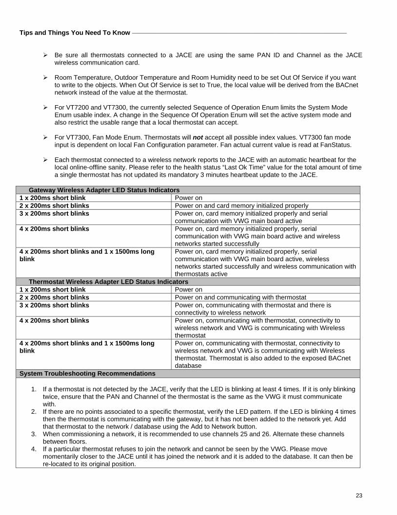
Gateway Wireless Adapter LED Status Indicators
1 x 200ms short blink Power on 2 x 200ms short blinks Power on and card memory initialized properly 3 x 200ms short blinks Power on, card memory initialized properly and serial
communication with VWG main board active 4 x 200ms short blinks Power on, card memory initialized properly, serial
communication with VWG main board active and wireless networks started successfully
4 x 200ms short blinks and 1 x 1500ms long blink
Power on, card memory initialized properly, serial communication with VWG main board active, wireless networks started successfully and wireless communication with thermostats active
Thermostat Wireless Adapter LED Status Indicators 1 x 200ms short blink Power on 2 x 200ms short blinks Power on and communicating with thermostat 3 x 200ms short blinks Power on, communicating with thermostat and there is
connectivity to wireless network 4 x 200ms short blinks Power on, communicating with thermostat, connectivity to
wireless network and VWG is communicating with Wireless thermostat
4 x 200ms short blinks and 1 x 1500ms long blink
Power on, communicating with thermostat, connectivity to wireless network and VWG is communicating with Wireless thermostat. Thermostat is also added to the exposed BACnet database
System Troubleshooting Recommendations 1. If a thermostat is not detected by the JACE, verify that the LED is blinking at least 4 times. If it is only blinking
twice, ensure that the PAN and Channel of the thermostat is the same as the VWG it must communicate with.
2. If there are no points associated to a specific thermostat, verify the LED pattern. If the LED is blinking 4 times then the thermostat is communicating with the gateway, but it has not been added to the network yet. Add that thermostat to the network / database using the Add to Network button.
3. When commissioning a network, it is recommended to use channels 25 and 26. Alternate these channels between floors.
4. If a particular thermostat refuses to join the network and cannot be seen by the VWG. Please move momentarily closer to the JACE until it has joined the network and it is added to the database. It can then be re-located to its original position.
24
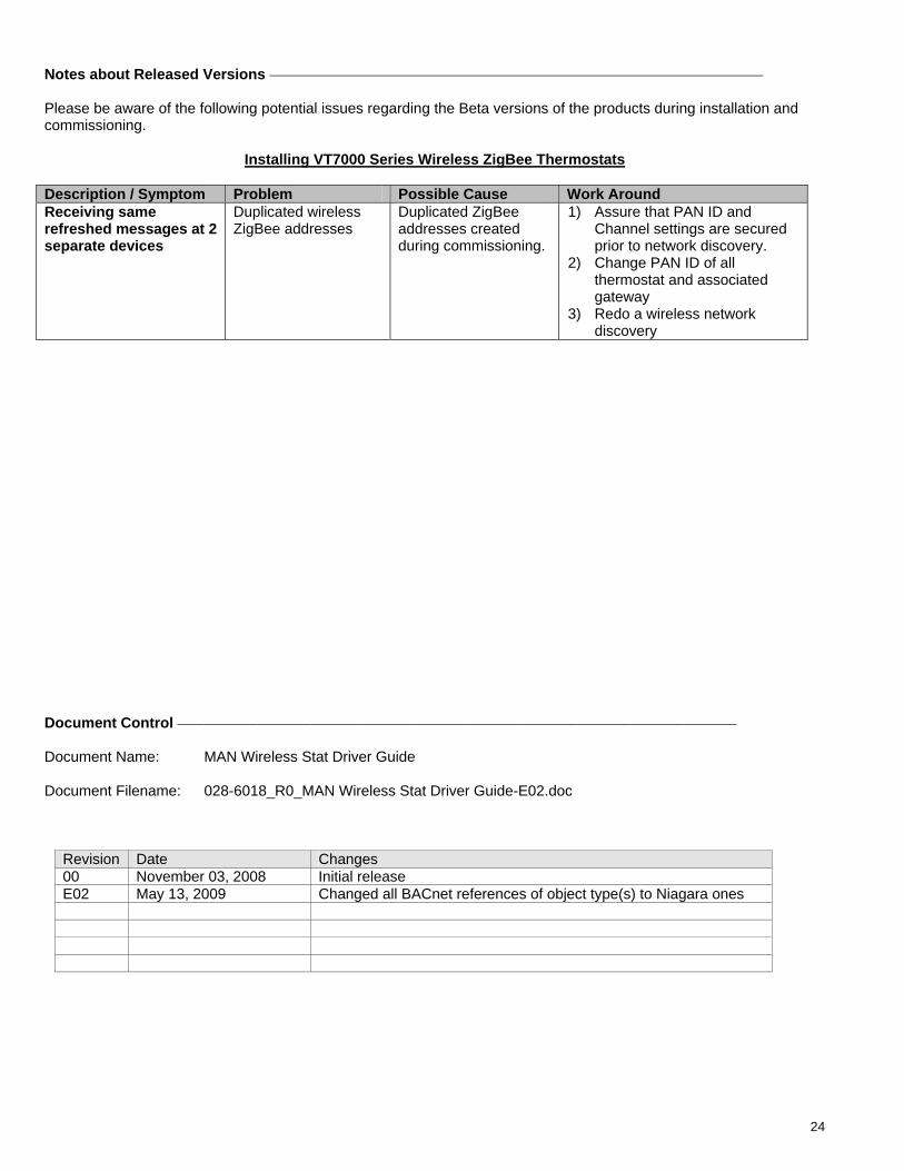
Notes about Released Versions
Please be aware of the following potential issues regarding the Beta versions of the products during installation and commissioning.
Installing VT7000 Series Wireless ZigBee Thermostats
Description / Symptom Problem Possible Cause Work Around Receiving same refreshed messages at 2 separate devices
Duplicated wireless ZigBee addresses
Duplicated ZigBee addresses created during commissioning.
1) Assure that PAN ID and Channel settings are secured prior to network discovery.
2) Change PAN ID of all thermostat and associated gateway
3) Redo a wireless network discovery
Document Control Document Name: MAN Wireless Stat Driver Guide Document Filename: 028-6018_R0_MAN Wireless Stat Driver Guide-E02.doc
Revision Date Changes 00 November 03, 2008 Initial release E02 May 13, 2009 Changed all BACnet references of object type(s) to Niagara ones