Embed Size (px)
Citation preview
Wireless Solar Water Splitting UsingSilicon-Based Semiconductors andEarth-Abundant CatalystsSteven Y. Reece,1* Jonathan A. Hamel,1 Kimberly Sung,1 Thomas D. Jarvi,1* Arthur J. Esswein,1
Joep J. H. Pijpers,2,3 Daniel G. Nocera2*
We describe the development of solar water-splitting cells comprising earth-abundant elements thatoperate in near-neutral pH conditions, both with and without connecting wires. The cells consistof a triple junction, amorphous silicon photovoltaic interfaced to hydrogen- and oxygen-evolvingcatalysts made from an alloy of earth-abundant metals and a cobalt|borate catalyst, respectively.The devices described here carry out the solar-driven water-splitting reaction at efficiencies of4.7% for a wired configuration and 2.5% for a wireless configuration when illuminated with 1 sun(100 milliwatts per square centimeter) of air mass 1.5 simulated sunlight. Fuel-forming catalystsinterfaced with light-harvesting semiconductors afford a pathway to direct solar-to-fuels conversionthat captures many of the basic functional elements of a leaf.
Although solar photovoltaic (PV) cellsnormally generate electricity, they canbe used to generate fuels such as hydro-
gen from water, thus providing a storage mecha-nism for sunlight (1). Such schemes mimic thephotosynthetic process within a leaf that convertsthe energy of sunlight into chemical energy bysplitting water to produce O2 and hydrogen equiv-alents (2). The primary steps of natural photo-synthesis involve the absorption of sunlight andits conversion into spatially separated electron-hole pairs. The holes of this wireless current arecaptured by the oxygen-evolving complex (OEC)of Photosystem II (PSII) to split H2O to O2. Theelectrons and protons produced as the by-productsof the OEC reaction are transferred to Photo-system I (PSI) to produce a reduced form of hy-drogen in the form of NADPH (the reduced formof nicotinamide adenine dinucleotide phosphate)(2). The separation of light collection/conversionfrom catalysis is compulsory to the photosyntheticfunction because electron/hole pairs are generatedone at a time and the water splitting reaction is afour electron-hole process (3). The multielectroncatalysts of PSII and PSI are therefore needed tobridge the light-driven one electron-hole “wirelesscurrent” of the light collection and conversion ap-paratus of the leaf to the four electron-hole chem-istry of water splitting.
A general approach for mimicking photo-synthesis is to generate O2 and H2 with inor-ganic materials using fuel-forming catalystsinterfaced with light-harvesting semiconduc-tors (4–6). Sunlight is absorbed by the semi-conductor and generates spatially separatedelectron-hole pairs. The electron-hole pairs of
this wireless current are captured with twocatalysts that drive the water-splitting reactionunder near-neutral pH conditions. A system ofthis type must generate electrons and holeswith enough energy to overcome both the ener-getic barrier of water oxidation (1.23 Vat stan-dard conditions) and any overpotentials neededto drive catalysis. Wireless photochemical cells(7, 8) and wired photoelectrochemical cells(PECs) (9–14) for solar-powered water split-ting have been realized, but practical problemsremain. Schemes for solar photochemical pro-duction of H2 and O2 from water at reasonableefficiency have relied on the use of prohibitive-ly expensive light-absorbing materials [e.g.,(Al)GaAs and GaInP], and/or fuel-forming cat-alysts (e.g., Pt, RuO2, IrO2), and strongly acidicor basic reaction media, which are corrosiveand expensive to manage over the large areasrequired for light harvesting. A focus of cur-rent research has been to mimic photosynthesiswith materials composed of earth-abundantelements in electrolytes near neutral pH con-ditions (15). The success of this approach willenable novel PEC and other light-harvesting(e.g., wireless) architectures to be engineeredto produce solar fuel at more practical costtargets.
Silicon is an attractive materials choice forconstructing an artificial leaf because of its earth-abundance and prevalence in the electronics andPV industries. The realization of a direct solar-to-fuel device based on silicon, however, must over-come the inherent corrosion of this semiconductorin nonacid electrolytes (16). Previous stand-alone,water-splitting PEC configurations have physical-ly shielded the silicon from the electrolyte andused wires (7, 11) or a conductive oxide (12, 13)to connect the semiconductor to the hydrogen-and/or oxygen-generating electrodes. Tunnelingoxide layers have also been explored recently tostabilize wired silicon photoanodes (17). Theseapproaches limit the application of Si in photo-chemical water splitting to a traditional, wired PEC
panel geometry, which has traditionally provedtoo costly for commercialization.
We show that water-splitting catalysts com-prising earth-abundant materials can be inte-grated with amorphous silicon with minimalengineering to enable direct solar-to-fuels con-version based on water splitting. For the O2-evolving catalyst, we use a cobalt catalyst (18),Co-OEC, that self-assembles upon oxidation ofCo2+ (19), self-heals (20), and can operate in buf-fered electrolyte with pure or natural water atroom temperature (21, 22). These attributes aresimilar to those of the OEC found in photo-synthetic organisms. Moreover, x-ray absorptionspectroscopy (23, 24) has established that theCo-OEC is a structural relative of Mn3CaO4–Mncubane (25–27) of the OEC of PSII, where Coreplaces Mn and the cubane is extended in acorner-sharing head-to-tail dimer (28). It hasbeen established that the Co-OEC, when inter-faced to semiconductors, enhances the efficiencyof solar-assisted water splitting (29–33). The H2-evolving catalyst is a ternary alloy, NiMoZn.These catalysts have been interfaced directlywith a commercial triple-junction amorphoussilicon (3jn-a-Si) solar cell (Xunlight Corp.) inwired and wireless configurations. For either,the cell uses stacked amorphous silicon andamorphous silicon-germanium alloy junctionsdeposited on a stainless steel substrate and coatedwith a 70-nm layer of indium tin oxide (ITO)(34). Although the abundance of Ge may be asource of debate (35), the use of a silicon-basedlight absorber represents a major step toward adevice composed of all earth-abundant materialsfor solar water splitting. Co-OEC is deposited di-rectly onto the ITO layer (the illuminated side ofthe cell). The NiMoZn alloy H2 catalyst was usedin two configurations: (i) deposited on a Ni meshsubstrate that is wired to the 3jn-a-Si solar celland (ii) deposited directly on the opposing stain-less steel surface of the 3jn-a-Si solar cell as awireless device. The devices, which have not beenoptimized for performance, may operate out of anopen container of water containing borate electro-lyte and with overall direct solar-to-fuels efficien-cies of 2.5% (wireless) and 4.7% (wired) whendriven by a solar cell of 6.2% and 7.7% light-to-electricity efficiency, respectively. The overall con-version efficiency of the wired cell indicates thata majority of the power from the solar cell can beconverted directly to solar fuels and that a simplyengineered, functional artificial leaf comprisingearth-abundant materials may be realized.
The PEC properties of the unmodified solarcell were characterized by operation of the cell asa photoanode in a three-electrode voltammetryconfiguration (3jn-a-Si working electrode, Ptcounter electrode, and Ag/AgCl reference elec-trode). Figure 1A plots the current densities ob-tained from the photoanode as a function ofthe applied potential, illumination, and electro-lyte conditions. In the absence of light (Fig. 1A,gray trace), a low anodic current density ( j < 0.05mA/cm2) was observed upon sweeping the 3jn-
1Sun Catalytix, Cambridge, MA 02139, USA. 2Department ofChemistry, Massachusetts Institute of Technology, Cambridge,MA 02139–4307, USA. 3Foundation for Fundamental Researchon Matter, Institute for Atomic and Molecular Physics, SciencePark 104, 1098 XG, Amsterdam, Netherlands.
*To whom correspondence should be addressed. E-mail:[email protected] (D.G.N.); [email protected] (S.Y.R.);[email protected] (T.D.J.)
www.sciencemag.org SCIENCE VOL 334 4 NOVEMBER 2011 645
REPORTS
on
Sep
tem
ber
17, 2
012
ww
w.s
cien
cem
ag.o
rgD
ownl
oade
d fr
om

a-Si anode from negative to positive potentialsfor E > 0.02 V versus the reversible hydrogenelectrode (RHE) (36). The onset potential (Eon)of this sweep may be defined as the potential atwhich the current changes from positive (cath-odic) to negative (anodic) values. Upon illumi-nation of the cell with 1 sun (100 mW/cm2) ofair mass (AM) 1.5 simulated sunlight (Fig. 1A,black trace) in 1M potassium borate electrolyte(pH 9.2), Eon shifted to more negative valuesand the magnitude of the anodic current ( jan)increased slightly (Eon = –0.14 V versus RHE,and jmax,an = 0.39 mA/cm2 at 0.55 V versusRHE, the most positive potential of the sweep).The photoanode current of the ITO-coated solarcell was limited under illumination in this con-figuration because water splitting does not occurappreciably in the absence of catalysts.
Upon addition of 0.25 mM Co2+(aq) to theborate electrolyte, Eon shifted to a more negativevalue (–0.37 V versus RHE) and the anodic cur-rent density increased dramatically ( jan = 4.17mA/cm2 at 0.55 V versus RHE) (Fig. 1A, redtrace). Illumination (AM 1.5) of the cell underthese conditions at fixed potential (E = –0.26 Vversus RHE) caused a thin film to form on theelectrode, and the current-time trace observed inFig. 1B was obtained. The photocurrent rose andreached a plateau at a value of 1.5 mA/cm2 dur-ing the 12-min course of the experiment, con-comitant with the evolution of bubbles at boththe photoanode surface and the Pt wire counterelectrode. Gas chromatography experiments iden-tified the evolved gases to be H2 and O2. Uponcompletion of the photoelectrolysis experiment,the surface coloration of the cell changed frompurple to light blue, which we ascribed to the for-mation of a thin film of the Co-OEC on the sur-face of the cell (see below). We attribute the risein current in Fig. 1B to the deposition of theCo-OEC catalyst and to water splitting. The ac-tivity of the photoanode increased with Co-OECloading, but a tradeoff existed as the catalystlayer grew thicker and blocked more of theincident radiation. Thus, short deposition times(~5 min) yielded photoanodes with optimum per-formance; the presence of borate maintains theoptimal film thickness and preserves the self-healing properties of the catalyst.
The Co-OEC | 3jn-a-Si photoelectrodes werecharacterized by scanning electron microscopy(SEM) and energy-dispersive x-ray (EDX) anal-ysis. We coated solar cells with both thin (5-mindeposition time) and thick (1-hour depositiontime) Co-OEC film layers. SEM analysis of crosssections (Fig. 2) allowed for determination ofthe thickness of the dried catalyst layer (thinfilm average, 85 nm; thick film average, 200 nm)and the thickness of the 3jn-a-Si layer (~1 mm);the average film thicknesses were provided fromseveral measurements. Low-energy EDX analy-sis was performed to estimate the elemental com-position of the substrate surface, as compared tothe pristine 3jn-a-Si cell (fig. S1). Cobalt wasobserved only for solar cells coated with Co-OEC
films, and the signal for Co was more intense forthe sample with thicker Co-OEC films.
We characterized the performance of thephotoanode with a Co-OEC film in the absenceof Co2+ in the electrolyte. The performance ofthe 3jn-a-Si coated with the 85-nm-thick films ofCo-OEC was assessed in solutions containing1M potassium borate electrolyte. The Co-OEC |3jn-a-Si cell exhibits a negative shift in the onsetpotential (Eon = –0.40 V versus RHE) and en-hanced anodic photocurrents ( jan = 4.4 mA/cm2),relative to an uncatalyzed 3jn-a-Si cell (Eon =– 0.14 V versus RHE; jan = 0.4 mA/cm2 ). Thedegree to which the Co-OEC film blocked in-coming light and inhibited the PV performanceof the cell was assessed by measuring the current-voltage curve in air under AM 1.5 illumination(fig. S2). Under these conditions, the 3jn-a-Sicell functioned as a pure PV cell and not a PEC.Due to deposition of the Co-OEC film, the short-circuit current ( jSC = current at zero applied bias)decreased from 6.5 to 5.9 mA/cm2, and the fillfactor decreased from 0.57 to 0.50. Thus, thecatalyst film of 85 nm decreased the PV per-formance by ~9% (8.0% to 7.3% for light-to-
electricity conversion efficiency). The precisionof our measurements for a given experiment ishigh (<1% error); the data presented are forthe highest performing cells.
Stand-alone operation of the cell with no ex-ternal applied potential from an electrical powersource (i.e., unassisted) was performed by usingthe Co-OEC | 3jn-a-Si photoanode in conjunc-tion with the NiMoZn cathode for H2 produc-tion. This earth-abundant H2 evolution catalystwas electrodeposited as described in the sup-porting online material (SOM). Figure S3 com-pares the activity of the ternary alloy, as deposited(37), and bare Ni metal in 1 M potassium bo-rate (pH 9.2). Over the potential range of the ex-periment, the alloy generated 50 times as muchcurrent as smooth Ni metal for the same geomet-ric surface area. When used in conjunction withthe Co-OEC | 3jn-a-Si photoanode, the NiMoZnwas deposited on a Ni wire mesh substrate thatwas wired to the steel substrate of the 3jn-a-Si celland placed between the light source and the photo-anode. The cell, which is schematically depictedin Fig. 3A, was illuminated with AM 1.5 solar-simulated light, and the solar-to-fuels efficiency
2 µm
A
L = 945 nm
Co-OEC
a-Si
Steel
L = 82 nmCo-OEC
a-Si
Steel
L = 1.0 µm
L = 225 nm
2 µm
B
Fig. 2. SEM of cross sections of the Co-OEC | 3jn-a-Si cell after (A) 5 min and (B) 1 hour depositionof the Co-OEC film.
Fig. 1. (A) Current-voltage plot of the 3jn-a-Si photoanode: in the dark (gray trace); under AM 1.5illumination (1 sun) (black trace); in the presence of 0.25 mM Co2+ in the dark (pink trace) and (redtrace) under 1 sun; and coated with a Co-OEC film under 1 sun (blue trace). The 3jn-a-Si cell was theworking electrode of a three-electrode configuration (Pt counter electrode, Ag/AgCl reference electrode,1 M potassium borate electrolyte, pH 9.2). Potentials were scanned from negative to positive to nega-tive values. (B) Bulk photoelectrolysis plot (current density versus time) during photodeposition of theCo-OEC film from 0.25 mM Co2+ and 1 M potassium borate (pH 9.2) under 1 sun illumination. The3jn-a-Si photoanode was held at –0.26 V versus RHE.
4 NOVEMBER 2011 VOL 334 SCIENCE www.sciencemag.org646
REPORTS
on
Sep
tem
ber
17, 2
012
ww
w.s
cien
cem
ag.o
rgD
ownl
oade
d fr
om
(SFE) for conversion of light and water into H2
and O2 was calculated using Eq. 1 (15),
SFE(%) = j • DE / S • 100% = J (mA/cm2) •
1.23 V / 100 (mW/cm2) • 100% (1)
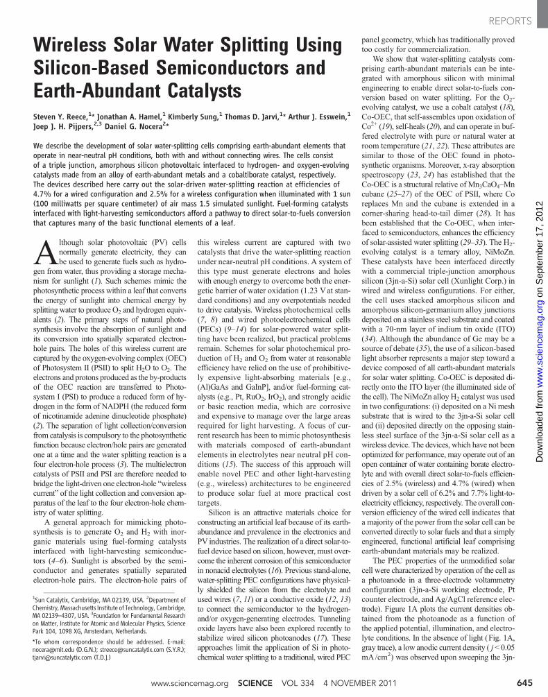
where j is the current density at the photoelec-trode, DE is the stored energy of the water-splitting reaction, and S is the total incident solarirradiance, which is provided by the AM1.5 lightsource at 100 mW/cm2. Figure 3A plots the effi-ciency and stability of Co-OEC | 3jn-a-Si | NiMoZnPEC cells operated in 1 M KBi (black trace)and 0.1MKOH (red trace) electrolyte. The over-all performance of the water-splitting cells wasdirectly correlated to their intrinsic performanceof the specific underlying PV sample. In Fig.3A, the 3jn-a-Si PV solar cell was 7.7% efficientand yielded an overall PEC cell efficiency of4.7% (Fig. 3A, black trace). We note that lightpassed through the mesh, which has a transmit-tance of ~85% (the efficiency reported here has
not been corrected for light blocking by themesh). Electrolysis efficiencies improved slight-ly upon operation of the cell in 0.1 M KOH elec-trolyte because of an increase in catalyst activity(Fig. 3A); however, the use of this electrolyteresulted in a rapid and catastrophic decline inactivity after 1 hour of photolysis (Fig. 3A, redtrace), concomitant with visible dissolution of the3jn-a-Si layer. This phenomenon had been previ-ously observed and attributed to pitting corrosionof the ITO coating by the KOH electrolyte (12).Conversely, the Co-OEC | 3jn-a-Si | NiMoZn cellexhibited significantly enhanced stability in borateelectrolyte (Figure 3A, black trace). O2 yieldswere measured with a phosphorescence-basedO2 sensor (fig. S4) and showed that virtually allof the electron-holes created during photoelec-trolysis were used to convert water into O2 at theanode (within the 5% error of the measurement).
The SFE may also be expressed as a directproduct of the efficiency of the solar conversionof the PV cell, ϕ(PV), and fuel generation ef-ficiency of water-splitting electrolysis, ϕ(WS),
which includes losses that arise from catalystoverpotentials and Ohmic resistances,
SFE (%) = ϕ(PV) • ϕ(WS) (2)
Thus,ϕ(WS) is calculated to be ~60%. Thisvalue compares well with cell efficiencies basedon 3jn-a-Si PVs in which the a-Si is isolated fromthe electrolyte [SFE = 6% for ϕ(PV) = 10%](7, 11, 12) and for higher-efficiency systemsusing expensive PV materials [SFE = 18% forϕ(PV) = 28%] (7–9). We note that, based onϕ(WS), higher overall cell efficiencies (>10%)may be readily achieved through the use of moreefficient PVs (38).
Awireless cell was constructed by depositionof the H2-evolving catalyst, NiMoZn, onto thesteel-backing substrate of the 3jn-a-Si cell. Theoverall device architecture is illustrated in Fig.3B.Movie S1 shows the operation of a 1 × 2 cm2
wireless Co-OEC | 3jn-a-Si | NiMoZn wafer thatwas immersed in an open container of electrolyte(1 M potassium borate, pH 9.2) and illuminatedwith 1 sun, AM 1.5 simulated sunlight. The cellarchitecture dictated that O2 bubbles evolved fromthe illuminated anode at the front face (5 to 47 s ofmovie S1) and bubbles of H2 evolved from thecathode at the back of thewireless cell (47 to 102 sof movie S1).
Oxygen yields (Fig. 3B) were determinedthrough operation in an electrochemical cell in aclosed configuration, in which the produced gaseswere analyzed using a mass spectrometer (MS).For this experiment, an Ar carrier gas was flowedover the headspace of the cell at a constant flowrate. The MS signal corresponds to the concentra-tion of O2 in the carrier gas, which was used todetermine the SFE for the wireless cell (see SOMfor experimental details); a SFE = 1.75% wasmeasured for a 3jn-a-Si solar cell with ϕ(PV) =6.2%. Based on the PEC cell of ϕ(PV) = 7.7%,we expect that minimal efficiencies of 4.7% maybe obtained from a properly engineered wirelesscell. For instance, in the present wireless cellconfiguration, protons generated at the front faceof the anodemust move around to the back side ofthe cell, where they are reduced at the cathode toH2. These relatively long distances for ion trans-port impose substantial Ohmic losses in the cell,resulting in lower ϕ(WS). These losses may bemitigated by increasing the conductance of thesolution. For instance, substituting the 1 M KBielectrolyte (specific conductivity = 26 mS/cm)with a mixture of 0.5 M KBi and 1.5 M KNO3
(specific conductivity = 126 mS/cm) resulted inan increase in the SFE from 1.75 to 2.5% (Fig.3B). In addition, future designs (e.g., flow cellor perforated Si cell) could increase the SFEfurther by decreasing the anode-cathode iontransport distance and bring the wireless cellperformance closer to that of the wired PECcell, which has a 1-mm gap between cathodeand anode (Fig. 3A).
The stability of thewireless cells was assessedby monitoring the O2 MS signal of a wireless
Fig. 3. (A) Plot of the efficiency versus time for Co-OEC | 3jn-a-Si | NiMoZn PEC cell (left) in 1 M potassiumborate (pH 9.2, black trace) and in 0.1 M KOH (pH 13, red trace) under AM 1.5 illumination. The traces arefor solar cells of 7.7% PV efficiency. The cells were operated in a two-electrode cell configuration. (B) MSsignal and SFE values for a wireless Co-OEC | 3jn-a-Si | NiMoZn cell under AM 1.5 illumination in 1 M KBi(red trace) and in 0.5 M KBi and 1.5 M KNO3 (blue trace). The cell was illuminated over the 2 hours of theexperiment; MS signal corresponds to the concentration of O2 in the carrier gas of the cell. The spikes in thedata originate from sudden release of gas bubbles that were adhered to the cells, resulting in a temporaryincrease of the O2 concentration in the headspace. SFE values were calculated as described in the SOM.
www.sciencemag.org SCIENCE VOL 334 4 NOVEMBER 2011 647
REPORTS
on
Sep
tem
ber
17, 2
012
ww
w.s
cien
cem
ag.o
rgD
ownl
oade
d fr
om

cell operating in 1 M KBi (fig. S5A). The cellwas stable for 10 hours, after which its perform-ance gradually declined to ~80% of its initialvalue over 24 hours. We have found that thestability of the cell is directly related to the na-ture of and preparative method for the transpar-ent conductive oxide barrier layer. For example,fluorine-doped tin oxide (FTO), when preparedand annealed on crystalline Si at high temper-atures (see SOM for experimental details), re-sults in a PEC cell with stable performance over30 hours of testing (fig. S5B), suggesting thatcells using crystalline Si with the catalysts de-scribed here have great practical value. Similarstrategies may be applied for protection of the3jn-a-Si cell; however, we note that they must becompatible with the low-temperature manufac-turing conditions of 3jn-a-Si.
The integration of earth-abundant water-splitting catalysts with photovoltaic silicon cellscaptures the functional elements of energy cap-ture and storage by a leaf. The ability to drivewater splitting directly without the use of wiresunder a simply engineered configuration opensnew avenues of exploration. For instance, thedesign described here could be adapted from apanel geometry to one based on freestanding(nano)particles in solution. Moreover, owingto the low solubility of O2 and H2 in water, thesolar-to-fuels conversion process may be drivenin the absence of a membrane. The H2 producedby photochemical water splitting may be collecteddirectly and used or combined with carbon di-oxide in a synthetic liquid fuels process externalto the cell. By constructing a simple, stand-alonedevice composed of silicon-based light absorb-ers and earth-abundant catalysts, the results de-scribed here provide a first step down a pathaligned with the low-cost systems engineeringand manufacturing (39) that is required for in-expensive direct solar-to-fuels systems.
References and Notes1. T. R. Cook et al., Chem. Rev. 110, 6474 (2010).2. J. Barber, Phil. Trans. Roy. Soc. A 365, 1007 (2007).3. T. A. Betley, Q. Wu, T. Van Voorhis, D. G. Nocera,
Inorg. Chem. 47, 1849 (2008).4. N. S. Lewis, D. G. Nocera, Proc. Natl. Acad. Sci. U.S.A.
103, 15729 (2006).5. D. G. Nocera, ChemSusChem 2, 387 (2009).6. D. Abbott, Proc. IEEE 98, 42 (2010).7. O. Khaselev, A. Bansal, J. A. Turner, Int. J. Hydrogen
Energy 26, 127 (2001).8. G. H. Lin, M. Kapur, R. C. Kainthla, J. O. M. Bockris,
Appl. Phys. Lett. 55, 386 (1989).9. O. Khaselev, J. A. Turner, Science 280, 425 (1998).10. S. Licht et al., J. Phys. Chem. B 104, 8920 (2000).11. R. E. Rocheleau, E. L. Miller, A. Misra, Energy Fuels 12, 3
(1998).12. N. A. Kelly, T. L. Gibson, Int. J. Hydrogen Energy 31,
1658 (2006).13. T. L. Gibson, N. A. Kelly, U.S. Patent 7,052,587 (2003).14. A. E. Delahoy, S. C. Gau, O. J. Murphy, M. Kapur,
J. O. M. Bockris, Int. J. Hydrogen Energy 10, 113 (1985).15. M. G. Walter et al., Chem. Rev. 110, 6446 (2010).16. X. G. Zhang, Silicon and Its Oxide (Kluwer Academic,
New York, 2001).17. Y. W. Chen et al., Nat. Mater. 10, 539 (2011).18. M. W. Kanan, D. G. Nocera, Science 321, 1072 (2008).19. Y. Surendranath, M. W. Kanan, D. G. Nocera,
J. Am. Chem. Soc. 132, 16501 (2010).20. D. A. Lutterman, Y. Surendranath, D. G. Nocera,
J. Am. Chem. Soc. 131, 3838 (2009).21. Y. Surendranath, M. Dincǎ, D. G. Nocera, J. Am.
Chem. Soc. 131, 2615 (2009).22. A. J. Esswein, Y. Surendranath, S. Y. Reece, D. G. Nocera,
Energy Environ. Sci. 4, 499 (2011).23. M. Risch et al., J. Am. Chem. Soc. 131, 6936 (2009).24. M. W. Kanan et al., J. Am. Chem. Soc. 132, 13692 (2010).25. J. Barber, Inorg. Chem. 47, 1700 (2008).26. E. M. Sproviero, J. A. Gascon, J. P. McEvoy, G. W. Brudvig,
V. S. Batista, J. Am. Chem. Soc. 130, 6728 (2008).27. Y. Umena, K. Kawakami, J.-R. Shen, N. Kamiya, Nature
473, 55 (2011).28. M. D. Symes, Y. Surendranath, D. A. Lutterman,
D. G. Nocera, J. Am. Chem. Soc. 133, 5174 (2011).29. J. A. Seabold, K. S. Choi, Chem. Mater. 23, 1105 (2011).30. E. M. P. Steinmiller, K. S. Choi, Proc. Natl. Acad.
Sci. U.S.A. 106, 20633 (2009).31. D. K. Zhong, J. Sun, H. Inumaru, D. R. Gamelin,
J. Am. Chem. Soc. 131, 6086 (2009).32. D. K. Zhong, D. R. Gamelin, J. Am. Chem. Soc. 132, 4202
(2010).
33. D. K. Zhong, M. Cornuz, K. Sivula, M. Grätzel,D. R. Gamelin, Energy Environ. Sci. 4, 1759 (2011).
34. X. Deng, E. A. Schiff, in Handbook of PhotovoltaicScience and Engineering, A. Luque, S. Hegedus, Eds.(Wiley, Chichester, England, 2003), pp. 505–565.
35. Germanium commodity summary, U.S. Geological Survey;available online at http://minerals.usgs.gov/minerals/pubs/commodity/germanium/mcs-2011-germa.pdf.
36. The RHE potential is that of the standard hydrogenelectrode (SHE) adjusted for the pH of the solution.Potentials (versus RHE) were calculated from themeasured values (versus Ag/AgCl) according to theequation E(RHE) = E(Ag/AgCl) + 0.197V + (0.059V × pH).
37. Mo leaches from alloys to furnish high-surface-areamaterials; thus, the activity of the alloy increases withleaching time [see (40, 41)]. After 9 days, leaching ceasesand a very active, high-surface-area material is obtained.
38. J. J. H. Pijpers, M. T. Winkler, Y. Surendranath,T. Buonassisi, D. G. Nocera, Proc. Natl. Acad. Sci. U.S.A.108, 10056 (2011).
39. B. D. James, G. N. Baum, J. Perez, K. N. Baum,U.S. Department of Energy, Dec. 2009. Available onlineat: http://www1.eere.energy.gov/hydrogenandfuelcells/pdfs/pec_technoeconomic_analysis.pdf.
40. B. E. Conway, L. Bai, Int. J. Hydrogen Energy 11, 533(1986).
41. J. Z. O. Stachurski, D. Pouli, J. A. Ripa, G. F. Pokrzyk,U.S. Patent 4,354,915 (1982).
Acknowledgments: Sun Catalytix acknowledges XunlightCorporation for providing the 3jn-a-Si cells and ARPA-E(DE-AR0000036) for funding. D.G.N. acknowledgessupport with grants from the National Science Foundation(CHE-0533150), AFOSR FA9550-09-1-0689, and theChesonis Family Foundation. J.J.H.P. performed work aspart of the Fellowships for Young Energy Scientistsprogram of the Foundation for Fundamental Research onMatter (FOM), which is financially supported by theNetherlands Organization for Scientific Research (NWO).NWO is also gratefully acknowledged for supplying aRubicon grant to J.J.H.P. J. Turner and E. Miller areacknowledged for helpful discussions.
Supporting Online Materialwww.sciencemag.org/cgi/content/full/science.1209816/DC1Materials and MethodsFigs. S1 to S5Movie S1
15 June 2011; accepted 15 September 2011Published online 29 September 2011;10.1126/science.1209816
Hot Carrier–Assisted IntrinsicPhotoresponse in GrapheneNathaniel M. Gabor,1 Justin C. W. Song,1,2 Qiong Ma,1 Nityan L. Nair,1 Thiti Taychatanapat,1,3
Kenji Watanabe,4 Takashi Taniguchi,4 Leonid S. Levitov,1 Pablo Jarillo-Herrero1*
We report on the intrinsic optoelectronic response of high-quality dual-gated monolayer andbilayer graphene p-n junction devices. Local laser excitation (of wavelength 850 nanometers)at the p-n interface leads to striking six-fold photovoltage patterns as a function of bottom- andtop-gate voltages. These patterns, together with the measured spatial and density dependence ofthe photoresponse, provide strong evidence that nonlocal hot carrier transport, rather than thephotovoltaic effect, dominates the intrinsic photoresponse in graphene. This regime, whichfeatures a long-lived and spatially distributed hot carrier population, may offer a path to hotcarrier–assisted thermoelectric technologies for efficient solar energy harvesting.
The photoresponse of semiconductors,which determines the performance of opto-electronic devices, is governed by energy
relaxation pathways of photoexcited electron-hole pairs: Energy transferred to the lattice is lost
as heat, while energy transported through chargecarriers may be used to drive an optoelectroniccircuit (1). Nanoscale systems can offer variousways to control energy relaxation pathways, po-tentially resulting in more efficient device op-
eration. Novel relaxation pathways that resultfrom electron confinement have been demon-strated in nanocrystal quantum dots and carbonnanotubes (2, 3). In graphene, energy relaxationpathways are strongly altered by the vanishingelectronic density of states (4–6). After initialrelaxation of photoexcited carriers (as a result ofelectron-electron scattering and optical phononemission), electron-lattice energy relaxation canbe quenched (4), which creates a bottleneck thatlimits further energy redistribution into the lat-tice. With electron-to-lattice energy relaxationquenched, a novel transport regime is reachedin which thermal energy is redistributed solely
1Department of Physics, Massachusetts Institute of Technol-ogy, Cambridge, MA 02139, USA. 2Harvard School of En-gineering and Applied Sciences, Harvard University, Cambridge,MA 02138, USA. 3Department of Physics, Harvard University,Cambridge, MA 02138, USA. 4National Institute for MaterialsScience, Namiki 1-1, Tsukuba, Ibaraki 305-0044, Japan.
*To whom correspondence should be addressed. E-mail:[email protected]
4 NOVEMBER 2011 VOL 334 SCIENCE www.sciencemag.org648
REPORTS
on
Sep
tem
ber
17, 2
012
ww
w.s
cien
cem
ag.o
rgD
ownl
oade
d fr
om
www.sciencemag.org SCIENCE VOL 334 18 NOVEMBER 2011 925
SPECIALSECTION
CR
ED
ITS
: (T
OP
MA
IN) F
OT
OS
EA
RC
H; (T
OP
SU
PE
RIM
PO
SE
D A
ND
BO
TT
OM
) K
IMB
ER
LY S
UN
G/S
UN
CA
TA
LYT
IX
The next time you groan when it’s time to
mow your lawn, take a second fi rst to mar-
vel at a blade of grass. Plants are so com-
monplace that it’s easy to take their wizardry
for granted. When they absorb sunlight, they
immediately squirrel away almost all of that
energy by using it to knit together a chemi-
cal fuel they use later to grow and multiply.
It sounds so simple. Yet it’s anything but.
Modern society runs on fossil fuels precisely
because researchers have never managed to
duplicate the chemical mastery of a fescue.
Now, with the side effects of our massive-
scale use of fossil fuels piling up (climate
change, acidifi ed oceans, oil spills, and so
on), researchers around the globe are strug-
gling to play catch-up with biology in hopes
of harnessing the sun’s energy to synthesize
gasoline or other fuels that are the bedrock of
modern society.
Humans, of course, already have ways to
capture solar energy. Today’s photovoltaic
solar cells typically trap 10% to 20% of the
energy in sunlight and convert it to electricity,
and PV prices continue to drop. But because
electricity is diffi cult to store on a large scale,
the effort to store sunlight’s energy in chemi-
cal fuels has risen to one of the grand chal-
lenges of the 21st century. “You’re talking
about turning the energy world on its head.
Today we turn hydrocarbon fuels into elec-
tricity. But in the future, we need to fi nd a
way to turn electricity [from sunlight] into
fuels,” says Daniel DuBois, a chemist at the
Pacific Northwest National Laboratory in
Richland, Washington.
The problem is daunting. Energy produc-
tion is the world’s largest enterprise. Today
the world consumes power at an average rate
of 17.75 trillion watts, or 17.75 terawatts,
85% of which starts out as fossil fuels, coal,
oil, and natural gas. Thanks to rising pop-
ulations and incomes, by 2050 the world’s
demand for power is expected to at least
double. To keep fossil fuels from stepping in
to fi ll that need, with potentially devastating
side effects, any new solar fuels technology
will have to provide power just as cheaply,
and it must have the potential to work on an
equally massive scale.
Enter artifi cial photosynthesis. Research-
ers around the globe are working to combine
materials that capture sunlight with cata-
lysts that can harness solar energy to synthe-
size fuels. This dream has been pursued for
decades. But recent strides are adding new zip
to the fi eld. “In the last 5 to 10 years, there
has been amazing progress,” DuBois says.
Anthony Rappé, a chemist at Colorado State
University, Fort Collins, agrees. However, he
adds, “the bottom line is we’re not there yet.”
Molecular shuffl e
To get there, most artifi cial photosynthesis
researchers look to natural photosynthesis
for inspiration. During photosynthesis, plants
absorb sunlight, water, and CO2. Then they use
two protein complexes—called photosystem
I and II—to split water and synthesize fuel.
First, in photosystem II, energy in sunlight
splits two water molecules into four hydrogen
ions (H+), four electrons, and a molecule of
oxygen (O2). The O2 wafts away as waste; the
protons and electrons are sent to photosystem
I and used to energize the coenzyme NADP to
NADPH, which in turn is used to help synthe-
size sugars—a key series of metabolic steps.
Of course, artif icial photosynthesis
researchers aim to make fuel not for plants
but for planes, trains, and automobiles. So
after splitting water into H+, electrons, and
oxygen molecules, most make very different
use of those ingredients. Some researchers are
working to combine the protons and electrons
with carbon dioxide (CO2) to make methane
gas and other hydrocarbon fuels (see sidebar,
p. 927). But most are working on what they
believe is a simpler approach: combining the
pieces they get from splitting pairs of water
molecules into molecules of O2 and hydrogen
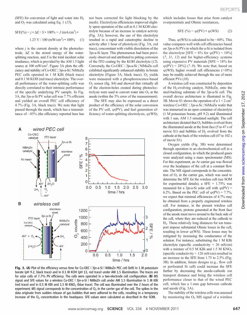
gas (H2). That H2 can then either be burned in The splits. An artifi cial leaf harnesses energy in
sunlight to split water into oxygen and hydrogen.
Published by AAAS
on
Sep
tem
ber
17, 2
012
ww
w.s
cien
cem
ag.o
rgD
ownl
oade
d fr
om

18 NOVEMBER 2011 VOL 334 SCIENCE www.sciencemag.org 926
CR
ED
ITS
(LE
FT
TO
RIG
HT
): Y
. U
ME
NA
, K
. K
AW
AK
AM
I, J
.-R
. S
HE
N A
ND
N. K
AM
IYA
; N
OC
ER
A L
AB
AT
MIT
; D
AV
ID R
OB
INS
ON
an engine or run through a fuel cell, where the water-splitting reaction runs in reverse: com-bining two H2s with O2 from the air to gener-ate water and electricity.
Although plants split water with seem-ing ease, it’s not a simple task, and it requires electrons to perform an intricate quantum-mechanical dance. Quantum mechanics dic-tates that electrons can exist only at discrete energy levels—or “bands.” In semiconduc-tors, for example, electrons can sit in either a lower energy state known as the valence band, where they are closely bound to the atom on which they sit, or a more freewheeling ener-gized state in the conduction band. Molecules like chlorophyll in plants act like tiny semi-conducting proteins. When they absorb sun-light, they kick an electron from the valence to the conduction band, leaving behind a posi-
tively charged electron vacancy called a hole.The holes are shuttled over to a compound
called the oxygen-evolving complex, which grabs two oxygen atoms, holds them close together, and rips out an electron from each to fi ll the holes. The electron-defi cient oxygens regain their stability by combining to form O2. In an artifi cial system, the electrons and protons liberated by water splitting then must migrate to a second catalyst, which combines them into two molecules of H2.
A successful artificial photosynthesis system must therefore meet several demands. It must absorb photons, use the energy to create energized electrons and holes, and steer those charges to two differ-ent catalysts to generate H2 and O2. It also has to be fast, cheap, and rugged. “This is a much more stringent set of require-ments than [those for] photovoltaics,” says John Turner, a water-splitting expert at the National Renewable Energy Laboratory (NREL) in Golden, Colorado.
In 1972, Japanese researchers took on the challenge by using particles of titanium dioxide to split water. The method was impractical for commercial use because TiO2, which absorbs only ultraviolet light, could make no use of 95% of the solar spectrum. But the demonstration inspired numerous other water-splitting systems. One setup uses molecular dyes made with ruthenium and other rare metals to absorb a variety of wavelengths of light and pass the charges to metal catalysts. Another, devel-oped by Turner’s NREL team, absorbed light with semiconductor wafers made from gal-lium arsenide (GaAs) and gallium indium phosphide (GaInP). A platinum electrode served as the catalyst to split water and gen-erate O2, while the semiconductor acted as the electrode to produce H2.
Unfortunately, these systems, too, had drawbacks. The metals in the best light-absorbing molecular dyes are too rare to be viable as a large-scale technology. To get enough ruthenium to power the world with water splitting, “we would need to harvest 1% of the Earth’s total continental crust to a depth of 1 kilometer,” Rappé says. Scale-up is prob-lematic with the semiconductor system as well. Although Turner’s devices convert 12% of sunlight to hydrogen, the materials would cost as much as $50,000 per square meter, according to an estimate by Harry Gray, a chemist at the California Institute of Technol-ogy (Caltech) in Pasadena. To be viable on a large scale, “we need to build something this good for $100 per square meter,” Gray says.
Wanted: the perfect catalyst
So more recently, much of the work in the water-splitting fi eld has begun to shift to try-ing to make light collectors and catalysts from abundant and cheap materials. A prime exam-
ple is the quest for H2-forming catalysts. Nat-ural photosynthesis carries out the reaction using enzymes called hydrogenases, which are built from the abundant elements iron and nickel. The enzymes have evolved until they can knit roughly 9000 pairs of hydrogen atoms into molecular H2 every second. Many early water-splitting systems performed the same reaction even faster using pure platinum as the catalyst. But platinum is too rare and expensive to be broadly useful.
In recent years, researchers have synthe-sized numerous compounds aimed at mim-icking the core complex of hydrogenases. All work more slowly (if at all), however, largely because they lack parts of the natu-ral protein around the core that optimizes the core’s activity. In 2008, Thomas Rauchfuss, a chemist at the University of Illinois, Urbana-
Champaign, and colleagues devised catalysts with molecular arms that act like a bucket bri-gade to ferry protons to the catalytic core. In the 12 August 2011 issue of Science (p. 863), DuBois and his colleagues described how they had refi ned this strategy further by creating a nickel-based catalyst that stitches 106,000 H2 molecules together every second (http://scim.ag/_DuBois).
The new H2 makers still aren’t ideal. They work only at high speed when researchers apply an electrical voltage of more than 1 volt to their system, a sizable energetic penalty. So DuBois’s team is now working to tweak the catalysts to work at a lower added volt-age. In a paper published online in Science on 29 September (http://scim.ag/Nocera), Dan Nocera, a chemist at the Massachu-setts Institute of Technology in Cambridge, reported that he and his colleagues had come up with another H2 catalyst that works with an extra voltage of only 35 thousandths of a volt (millivolts). It, too, is made from rela-
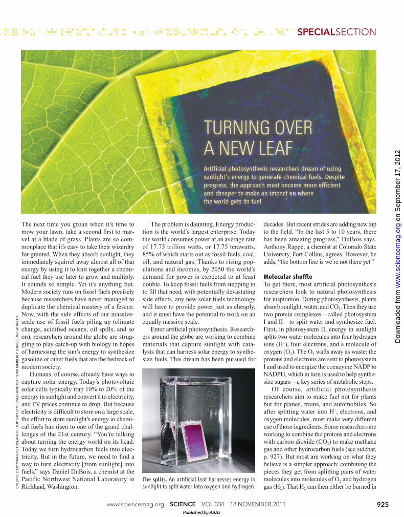
Box step. Natural photosynthesis depends on a molecular cube (left) made from manganese atoms (purple), oxygens (red), and a calcium atom (yellow).
The catalyst splits water molecules (blue), generating molecular oxygen. Synthetic versions (center and right) have similar cube-shaped cores.
Published by AAAS
on
Sep
tem
ber
17, 2
012
ww
w.s
cien
cem
ag.o
rgD
ownl
oade
d fr
om

www.sciencemag.org SCIENCE VOL 334 18 NOVEMBER 2011 927
SPECIALSECTION
tively cheap metals: molybdenum, nickel, and zinc. But Nocera’s catalyst is slower than DuBois’s, so the race is on to marry the best attributes of each.
Balancing speed and extra energy input has been an even tougher problem with the catalysts needed for other reactions in water splitting, which grabs oxygen atoms from two water molecules and links them together as O2. In 2008, Nocera and his team made head-lines when they unveiled a cobalt-phosphate (Co-Pi) catalyst that works at 300 millivolts applied potential over the minimum 1.23 elec-tron volts required to link two oxygen atoms. The group followed that up with a nickel-borate compound that does much the same thing. And in the 29 September online paper, the researchers described a triple-layer silicon wafer lined with their Co-Pi catalyst on one face and with their H2 catalyst on the other. The silicon absorbed sunlight and passed charges to the two catalysts, which then split water. “I love the triple junction. It’s pretty sexy,” says Felix Castellano, a chemist at Bowling Green University in Ohio.
Turner cautions that the overall effi ciency of the device—it converts just 5% of the energy in sunlight to hydrogen—is still too low, and the extra voltage input required is still too high, to be commercially useful. Nocera counters that this initial system was built using amorphous silicon wafers as the sun-light absorbers. Such wafers are only 8% effi -cient in converting light to electrical charges. An artifi cial leaf based on crystalline silicon solar cells, which are 20% efficient, could convert sunlight to chemical energy with an effi ciency of 12%, he says. But Nocera’s team has yet to demonstrate such a device.
Other related catalysts are also entering the picture. Charles Dismukes, a chemist at Rutgers University in Piscataway, New Jer-sey, and colleagues reported last year that they had made a series of O2-forming catalysts using lithium, manganese, and oxygen. And earlier this year, Dismukes’s team reported in the Journal of the American Chemical Society
that they had created another oxygen-forming complex with cobalt and oxygen. What’s unique about all these new oxygen formers is that they share almost an identical cubic molecular structure, which is also at the heart of the natural O2-forming complex in photo-system II. “There is only one blueprint from biology that can be copied,” Dismukes says.
Many other advances are also making their way out of the lab. Castellano and colleagues have recently created a family of cheap poly-mers capable of absorbing the energy from
low-energy green photons and reemitting it as lower numbers of higher energy blue photons. They are now working on using this upcon-version process to make use of more of the solar spectrum to split water. Researchers led by Steve Cronin of the University of Southern California in Los Angeles are adding metal nanoparticles to conventional solar absorb-ers as another way to convert low-energy photons to electrical charges that can then be harnessed to improve the effi ciency of water-splitting setups. And Gray’s group at Caltech has teamed up with students at 17 other uni-versities to create a “solar army” that has already made progress in fi nding new water-splitting catalysts.
These and other advances will need to con-tinue if artifi cial photosynthesis ever hopes
to contend with fossil fuels. With today’s low natural gas prices, companies can use a mature technology called steam reform-ing to convert natural gas to hydrogen at a cost of about $1 to $1.50 per kilogram of H2 generated, which contains about the same amount of energy as a gallon of gasoline. Yet a recent analysis by Turner and his colleagues showed that, even if researchers could create an artifi cial photosynthesis system that cost $200 per square meter for the equipment and was 25% effi cient at converting sunlight to H2, the H2 would still cost $2.55 per kilogram. That’s not saying artificial photosynthesis isn’t worth pursuing—only that fossil fuels are the leading energy source for a reason, and they won’t be easy to dethrone.
–ROBERT F. SERVICE
Sunlight in Your Tank—Right Away
Using sunlight to split water and generate hydrogen doesn’t make the most useful chemical fuel. To use hydrogen on a large scale, societies would have to develop a new infrastructure to store, trans-port, and distribute the energy carrier. With that limitation in mind, some researchers are looking to use artifi cial photosynthesis to generate hydrocarbon fuels like those we already burn.
Their goal is essentially to run combustion in reverse, starting with carbon dioxide (CO2) and water and using the energy in sunlight to knit the chemical bonds needed to make hydrocarbons, such as gaseous methane and liquid methanol. “That’s a technology that’s going to come,” says Harry Gray, a chemist at the California Institute of Technology in Pasadena. “But it is hard.”
The diffi culty is that CO2 is a very stable molecule. In converting CO2 to hydrocarbons, the fi rst step is to strip off one of the oxygen atoms, leaving behind a molecule of carbon monox-ide (CO), a more reactive combination of carbon and oxygen. CO can then be combined with molecular hydrogen and converted into liquid hydrocarbons using an industrial process known as Fischer-Tropsch synthesis.
That fi rst step of converting CO2 to CO is the energy hog. A minimum of 1.33 electron volts (eV) of energy must be applied to carry out the reaction. Over the past few decades, researchers have developed numerous catalysts that carry out the process. But virtually all of them require adding a lot of extra energy, typically another 1.5 eV. As a result, it would take far more energy to synthesize a hydrocarbon fuel than the fuel’s molecules could store in their chemical bonds.
On 29 September, however, researchers led by Richard Masel of Dioxide Materials in Cham-paign, Illinois, and Paul Kenis of the University of Illinois, Urbana-Champaign, reported online in Science (http://scim.ag/_Masel) that they’ve come up with a less energy-intensive way to con-vert CO2 to CO. By adding a type of solvent called an ionic liquid to the CO2 in their setup, they reduced the added energy needed for splitting CO2 by 90%. Ionic liquids are liquid salts that are adept at stabilizing negatively charged compounds. Adding a negative charge is the fi rst step required to convert CO2 to CO; the Illinois researchers suspect the increased stability reduces the voltage needed to do the job.
The Illinois catalysts are slow, and so far the researchers have not powered them with electrical charges from a solar cell. But other labs are taking an approach that looks more like full-fl edged artifi cial photosynthesis. At Lawrence Berkeley National Laboratory in California, for example, chemist Heinz Frei and his colleagues reported in 2005 that for the fi rst time they had used energy from visible light to convert CO2 to CO using a porous catalyst made from silica and impregnated with zinc and copper. Frei’s team has used related catalysts to split water to generate molecular hydrogen. Now the group is working to put the two pieces together to combine light-generated CO and H2 to make methanol, one of the simplest hydrocarbons.
It’s not ExxonMobil yet. But with further developments, the technology could lead to fuels made basically from air, water, and sunlight. –R.F.S.
Published by AAAS
on
Sep
tem
ber
17, 2
012
ww
w.s
cien
cem
ag.o
rgD
ownl
oade
d fr
om
www.sciencemag.org SCIENCE VOL 315 9 FEBRUARY 2007 789
CR
ED
IT: C
OU
RT
ES
Y O
F D
. N
OC
ER
A
SPECIALSECTION
Hydrogen seems like an ideal fuel. Com-
bine it with oxygen in a fuel cell, and it
produces water and electricity, without the
noxious pollutants that accompany the burn-
ing of most fossil fuels. But it has a dark side:
Although there is plenty of hydrogen around,
it’s bound with other atoms in complex mol-
ecules, and it takes large amounts of energy
to strip it free. Moreover, most hydrogen
today is made from fossil fuels, releasing
vast quantities of carbon dioxide in the
process. Daniel Nocera is hoping to change
that. The Massachusetts Institute of Technol-
ogy (MIT) chemist is looking for new ways
to use sunlight to split water into oxygen and
hydrogen. In essence, Nocera is trying to run
a fuel cell in reverse. “Why can’t we reengi-
neer the fuel cell backwards?” he asks. “Con-
ceptually, it’s very easy.”
His quest had a colorful start. Like many
fellow Grateful Dead fans with their tie-
dyed T-shirts, Nocera, 49, was fascinated by
colors when he was growing up—not by the
colors themselves, however, but by the
processes that lie behind them. “I wanted to
understand the colors of materials,” Nocera
says. And that sparked his interest in chem-
istry. In between going to some 80 Dead
shows, he learned that the colors we see are
driven by which frequencies of light are
absorbed and reflected by materials. When
that light is absorbed, it kicks electrons out
of their relaxed state, sending them into a
dancing frenzy. As they return to their rela-
tive rest, they give off heat. By the time
Nocera was a graduate student at the Cali-
fornia Institute of Technology in Pasadena,
he was wondering how he could design sys-
tems to capture electrons excited by sun-
light and use them to make fuel. “Right out
of the blocks, I was interested in solar
energy conversion,” Nocera says. Or, as
Deadheads might put it, f inding a way to
hold onto the light.
Plants do this by photosynthesis: Two
massive protein complexes split water and
carbon dioxide and forge new energy-storing
bonds in sugar molecules. At the heart of the
process is the harnessing of electrons excited
by sunlight. Nocera is looking for novel cata-
lysts that will perform some of these tasks
more efficiently.
Five years ago, he and then–graduate stu-
dent Alan Heyduk designed a ruthenium-
based catalyst that uses light energy to strip
protons and electrons from an acid and stitch
them together to make H2
molecules.
(They’re still trying to f ind a cousin that
does the same thing with water rather than
an acid.) But that was the easy step. It’s even
more difficult to grab lone oxygens liberated
by splitting water and link them together to
form O2—a step that would be needed to
complete the water-splitting reactions and
maximize the eff iciency of the process.
“That requires a certain organization,” says
Heyduk, now a chemistry professor at the
University of California, Irvine. And it’s one
of the reasons there’s been so little progress
in recent decades in devising catalysts that
turn out O2.
But there could soon be a new glimmer of
progress. Nocera says his group is close to
publishing results with a new ruthenium-
based catalyst that absorbs light and uses the
energy to stitch oxygen atoms together to
make O2. The new catalyst isn’t very effi-
cient yet. But it works the way he expected it
to, Nocera says, which gives him confidence
that they’re beginning to understand how to
control the motion and bonding of different
atoms with their new catalysts. Although
Heyduk says he hasn’t heard the details of the
new catalyst yet, “any system where they can
turn water to O2
is a huge advance because of
the difficulty of the problem.”
Nocera acknowledges that even this and
other advances his group has made are baby
steps compared to what’s needed for an
industrial version of the technology. One
problem is that Nocera’s catalysts thus far
contain ruthenium, a rare and expensive
metal. But Nocera is hoping to find cheaper
materials that work as well. He recently
launched a new project with MIT colleagues
to synthesize a multitude of novel metal
oxide compounds for testing as possible
water-splitting catalysts.
A handful of other groups around the
world are engaged in related efforts. One
approach pursued by researchers at the
National Renewable Energy Laboratory in
Golden, Colorado, for example, uses semi-
conductors to absorb sunlight and create
electrical charges that are then used to split
water. Although this approach is currently
more efficient than Nocera’s catalysts, the
semiconductors needed are still too costly to
be commercially viable. At this point,
Nocera argues, all such strategies are worth
pursuing. “I’m not sure what the winner will
be that is able to make energy without
adding extra CO2
to the atmosphere,”
Nocera says. “A failing of energy R&D for
the last 30 years in the United States has
been that it has been treated as an engineer-
ing problem, with a little ‘r’ component and
a big ‘D.’ There needs to be an ‘R’ bigger
than the ‘D.’ There are whole new areas of
science and engineering that need to be dis-
covered to solve this problem.”
Still, Nocera is convinced that the broad
community of researchers now being
inspired to find a carbon-neutral source of
energy will succeed. “I’ll guarantee it,” he
says. “I think science can deliver a cheap and
efficient solution. I believe it deeply.”
–ROBERT F. SERVICE
P R O F I L E : D A N I E L N O C E R A
Looking for a clean way to produce hydrogen, Daniel Nocera wants to run
a fuel cell backward, powered by sunlight
Hydrogen Economy? Let Sunlight Do the Work
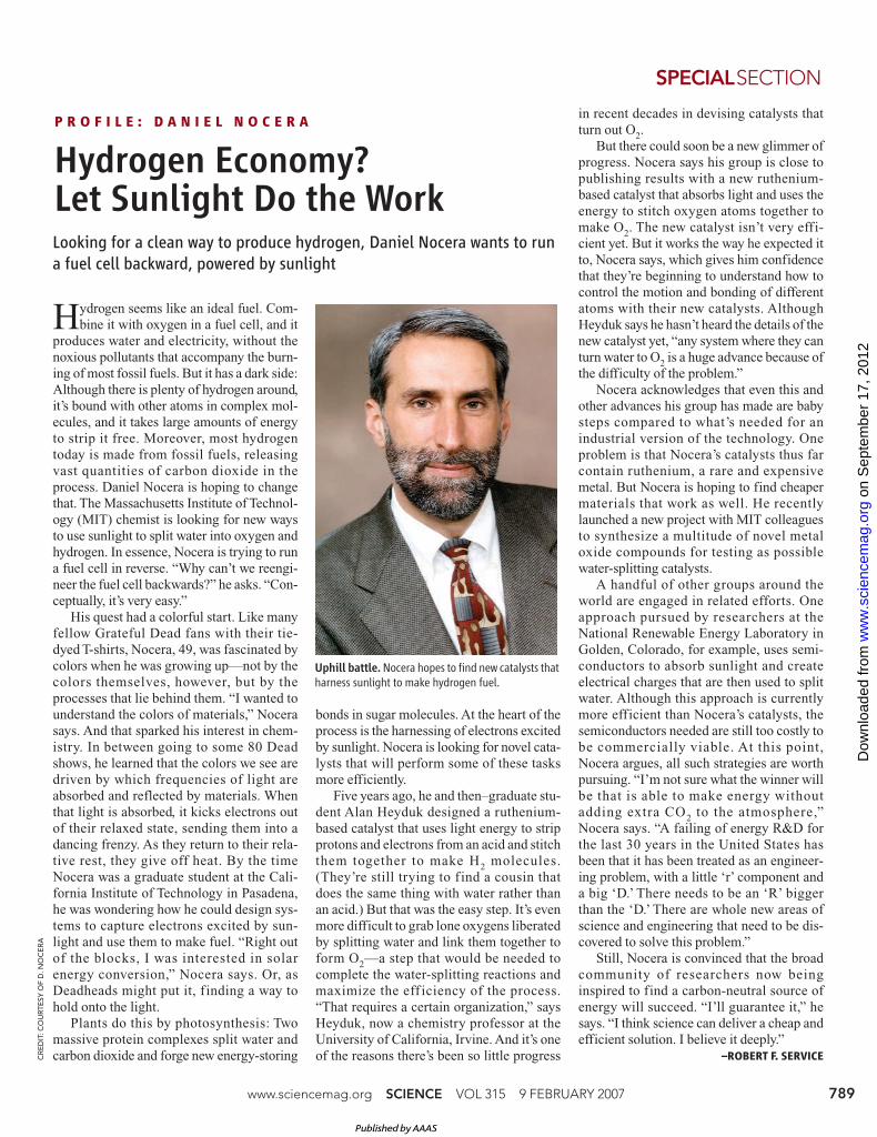
Uphill battle. Nocera hopes to find new catalysts that
harness sunlight to make hydrogen fuel.
Published by AAAS
on
Sep
tem
ber
17, 2
012
ww
w.s
cien
cem
ag.o
rgD
ownl
oade
d fr
om