Embed Size (px)
Citation preview
Computer Networks 52 (2008) 2292–2330
Contents lists available at ScienceDirect
Computer Networks
journal homepage: www.elsevier .com/locate /comnet
Wireless sensor network survey
Jennifer Yick, Biswanath Mukherjee, Dipak Ghosal *
Department of Computer Science, University of California, Davis, CA 95616, United States
a r t i c l e i n f o
Article history:Received 20 March 2007Received in revised form 3 April 2008Accepted 7 April 2008Available online 14 April 2008
Responsible Editor: E. Ekici
Keywords:Wireless sensor networkProtocolsSensor network servicesSensor network deploymentSurvey
1389-1286/$ - see front matter � 2008 Elsevier B.Vdoi:10.1016/j.comnet.2008.04.002
* Corresponding author. Tel.: +1 530 754 9251; faE-mail addresses: [email protected] (J. Yick),
s.edu (B. Mukherjee), [email protected] (D. Gh1 An actuator is an electro-mechanical device that
different components in a system. In a sensor node,different sensing devices, adjust sensor parameters,monitor power in the sensor node.
a b s t r a c t
A wireless sensor network (WSN) has important applications such as remote environmen-tal monitoring and target tracking. This has been enabled by the availability, particularly inrecent years, of sensors that are smaller, cheaper, and intelligent. These sensors areequipped with wireless interfaces with which they can communicate with one anotherto form a network. The design of a WSN depends significantly on the application, and itmust consider factors such as the environment, the application’s design objectives, cost,hardware, and system constraints. The goal of our survey is to present a comprehensivereview of the recent literature since the publication of [I.F. Akyildiz, W. Su, Y. Sankarasubr-amaniam, E. Cayirci, A survey on sensor networks, IEEE Communications Magazine, 2002].Following a top-down approach, we give an overview of several new applications and thenreview the literature on various aspects of WSNs. We classify the problems into three dif-ferent categories: (1) internal platform and underlying operating system, (2) communica-tion protocol stack, and (3) network services, provisioning, and deployment. We review themajor development in these three categories and outline new challenges.
� 2008 Elsevier B.V. All rights reserved.
1. Introduction may be attached to the sensor node to measure properties
Wireless sensor networks (WSNs) have gained world-wide attention in recent years, particularly with the prolif-eration in Micro-Electro-Mechanical Systems (MEMS)technology which has facilitated the development of smartsensors. These sensors are small, with limited processingand computing resources, and they are inexpensive com-pared to traditional sensors. These sensor nodes can sense,measure, and gather information from the environmentand, based on some local decision process, they can trans-mit the sensed data to the user.
Smart sensor nodes are low power devices equippedwith one or more sensors, a processor, memory, a powersupply, a radio, and an actuator.1 A variety of mechanical,thermal, biological, chemical, optical, and magnetic sensors
. All rights reserved.
x: +1 530 752 [email protected]).can be used to controlactuators can actuatemove the sensor, or
of the environment. Since the sensor nodes have limitedmemory and are typically deployed in difficult-to-accesslocations, a radio is implemented for wireless communica-tion to transfer the data to a base station (e.g., a laptop, apersonal handheld device, or an access point to a fixed infra-structure). Battery is the main power source in a sensornode. Secondary power supply that harvests power fromthe environment such as solar panels may be added to thenode depending on the appropriateness of the environmentwhere the sensor will be deployed. Depending on the appli-cation and the type of sensors used, actuators may be incor-porated in the sensors.
A WSN typically has little or no infrastructure. It con-sists of a number of sensor nodes (few tens to thousands)working together to monitor a region to obtain data aboutthe environment. There are two types of WSNs: structuredand unstructured. An unstructured WSN is one that con-tains a dense collection of sensor nodes. Sensor nodesmay be deployed in an ad hoc manner2 into the field. Once
2 In ad hoc deployment, sensor nodes may be randomly placed into thefield.

J. Yick et al. / Computer Networks 52 (2008) 2292–2330 2293
deployed, the network is left unattended to perform moni-toring and reporting functions. In an unstructured WSN, net-work maintenance such as managing connectivity anddetecting failures is difficult since there are so many nodes.In a structured WSN, all or some of the sensor nodes are de-ployed in a pre-planned manner.3 The advantage of a struc-tured network is that fewer nodes can be deployed withlower network maintenance and management cost. Fewernodes can be deployed now since nodes are placed at spe-cific locations to provide coverage while ad hoc deploymentcan have uncovered regions.
WSNs have great potential for many applications in sce-narios such as military target tracking and surveillance[2,3], natural disaster relief [4], biomedical health monitor-ing [5,6], and hazardous environment exploration and seis-mic sensing [7]. In military target tracking andsurveillance, a WSN can assist in intrusion detection andidentification. Specific examples include spatially-corre-lated and coordinated troop and tank movements. Withnatural disasters, sensor nodes can sense and detect theenvironment to forecast disasters before they occur. In bio-medical applications, surgical implants of sensors can helpmonitor a patient’s health. For seismic sensing, ad hocdeployment of sensors along the volcanic area can detectthe development of earthquakes and eruptions.
Unlike traditional networks, a WSN has its own designand resource constraints. Resource constraints include alimited amount of energy, short communication range,low bandwidth, and limited processing and storage in eachnode. Design constraints are application dependent and arebased on the monitored environment. The environmentplays a key role in determining the size of the network,the deployment scheme, and the network topology. Thesize of the network varies with the monitored environ-ment. For indoor environments, fewer nodes are requiredto form a network in a limited space whereas outdoor envi-ronments may require more nodes to cover a larger area.An ad hoc deployment is preferred over pre-planneddeployment when the environment is inaccessible by hu-mans or when the network is composed of hundreds tothousands of nodes. Obstructions in the environment canalso limit communication between nodes, which in turn af-fects the network connectivity (or topology).
Research in WSNs aims to meet the above constraints byintroducing new design concepts, creating or improvingexisting protocols, building new applications, and develop-ing new algorithms. In this study, we present a top-down ap-proach to survey different protocols and algorithmsproposed in recent years. Our work differs from other sur-veys as follows:
� While our survey is similar to [1], our focus has been tosurvey the more recent literature.
� We address the issues in a WSN both at the individualsensor node level as well as a group level.
� We survey the current provisioning, management andcontrol issues in WSNs. These include issues such as
3 In pre-planned deployment, sensor nodes are pre-determined to beplaced at fixed locations.
localization, coverage, synchronization, network secu-rity, and data aggregation and compression.
� We compare and contrast the various types of wirelesssensor networks.
� Finally, we provide a summary of the current sensortechnologies.
The remainder of this paper is organized as follows:Section 2 gives an overview of the key issues in a WSN.Section 3 compares the different types of sensor networks.Section 4 discusses several applications of WSNs. Section 5presents issues in operating system support, supportingstandards, storage, and physical testbed. Section 6 summa-rizes the control and management issues. Section 7 classi-fies and compares the proposed physical layer, data-linklayer, network layer, and transport layer protocols. Section8 concludes this paper. Appendix A compares the existingtypes of WSNs. Appendix B summarizes the sensor tech-nologies. Appendix C compares sensor applications withthe protocol stack.
2. Overview of key issues
Current state-of-the-art sensor technology provides asolution to design and develop many types of wireless sen-sor applications. A summary of existing sensor technolo-gies is provided in Appendix A. Available sensors in themarket include generic (multi-purpose) nodes and gate-way (bridge) nodes. A generic (multi-purpose) sensornode’s task is to take measurements from the monitoredenvironment. It may be equipped with a variety of deviceswhich can measure various physical attributes such aslight, temperature, humidity, barometric pressure, veloc-ity, acceleration, acoustics, magnetic field, etc. Gateway(bridge) nodes gather data from generic sensors and relaythem to the base station. Gateway nodes have higher pro-cessing capability, battery power, and transmission (radio)range. A combination of generic and gateway nodes is typ-ically deployed to form a WSN.
To enable wireless sensor applications using sensor tech-nologies, the range of tasks can be broadly classified intothree groups as shown in Fig. 1. The first group is the system.Each sensor node is an individual system. In order to supportdifferent application software on a sensor system, develop-ment of new platforms, operating systems, and storageschemes are needed. The second group is communicationprotocols, which enable communication between the appli-cation and sensors. They also enable communication be-tween the sensor nodes. The last group is services whichare developed to enhance the application and to improvesystem performance and network efficiency.
From application requirements and network manage-ment perspectives, it is important that sensor nodes arecapable of self-organizing themselves. That is, the sensornodes can organize themselves into a network and subse-quently are able to control and manage themselves effi-ciently. As sensor nodes are limited in power, processingcapacity, and storage, new communication protocols andmanagement services are needed to fulfil theserequirements.

Services
LocalizationCoverageSecurity
SynchronizationData Aggregation
Cross-layerOptimization
CommunicationProtocol
Transport LayerNetwork Layer
Data Link Layer
SystemPlatform
Operating SystemSupport
Perform EvaluationStorage
Applications
Sensor Technology
Fig. 1. Broad classification of various issues in a WSN.
4 QoS defines parameters such as end-to-end delay which must beguaranteed to an application/user.
2294 J. Yick et al. / Computer Networks 52 (2008) 2292–2330
The communication protocol consists of five standardprotocol layers for packet switching: application layer,transport layer, network layer, data-link layer, and physicallayer. In this survey, we study how protocols at differentlayers address network dynamics and energy efficiency.Functions such as localization, coverage, storage, synchro-nization, security, and data aggregation and compressionare explored as sensor network services.
Implementation of protocols at different layers in theprotocol stack can significantly affect energy consumption,end-to-end delay, and system efficiency. It is important tooptimize communication and minimize energy usage. Tra-ditional networking protocols do not work well in a WSNsince they are not designed to meet these requirements.Hence, new energy-efficient protocols have been proposedfor all layers of the protocol stack. These protocols employcross-layer optimization by supporting interactions acrossthe protocol layers. Specifically, protocol state informationat a particular layer is shared across all the layers to meetthe specific requirements of the WSN.
As sensor nodes operate on limited battery power, en-ergy usage is a very important concern in a WSN; and therehas been significant research focus that revolves aroundharvesting and minimizing energy. When a sensor nodeis depleted of energy, it will die and disconnect from the
network which can significantly impact the performanceof the application. Sensor network lifetime depends onthe number of active nodes and connectivity of the net-work, so energy must be used efficiently in order to maxi-mize the network lifetime.
Energy harvesting involves nodes replenishing its en-ergy from an energy source. Potential energy sources in-clude solar cells [8,9], vibration [10], fuel cells, acousticnoise, and a mobile supplier [11]. In terms of harvestingenergy from the environment [12], solar cell is the currentmature technique that harvest energy from light. There isalso work in using a mobile energy supplier such as a robotto replenish energy. The robots would be responsible incharging themselves with energy and then delivering en-ergy to the nodes.
Energy conservation in a WSN maximizes network life-time and is addressed through efficient reliable wirelesscommunication, intelligent sensor placement to achieveadequate coverage, security and efficient storage manage-ment, and through data aggregation and data compression.The above approaches aim to satisfy both the energy con-straint and provide quality of service (QoS)4 for the applica-tion. For reliable communication, services such ascongestion control, active buffer monitoring, acknowledge-ments, and packet-loss recovery are necessary to guaranteereliable packet delivery. Communication strength is depen-dent on the placement of sensor nodes. Sparse sensor place-ment may result in long-range transmission and higherenergy usage while dense sensor placement may result inshort-range transmission and less energy consumption. Cov-erage is interrelated to sensor placement. The total numberof sensors in the network and their placement determine thedegree of network coverage. Depending on the application, ahigher degree of coverage may be required to increase theaccuracy of the sensed data. In this survey, we review newprotocols and algorithms developed in these areas.
3. Types of sensor networks
Current WSNs are deployed on land, underground, andunderwater. Depending on the environment, a sensor net-work faces different challenges and constraints. There arefive types of WSNs: terrestrial WSN, underground WSN,underwater WSN, multi-media WSN, and mobile WSN(see Appendix B).
Terrestrial WSNs [1] typically consist of hundreds tothousands of inexpensive wireless sensor nodes deployedin a given area, either in an ad hoc or in a pre-plannedmanner. In ad hoc deployment, sensor nodes can bedropped from a plane and randomly placed into the targetarea. In pre-planned deployment, there is grid placement,optimal placement [13], 2-d and 3-d placement [14,15]models.
In a terrestrial WSN, reliable communication in a denseenvironment is very important. Terrestrial sensor nodesmust be able to effectively communicate data back to thebase station. While battery power is limited and may not

J. Yick et al. / Computer Networks 52 (2008) 2292–2330 2295
be rechargeable, terrestrial sensor nodes however can beequipped with a secondary power source such as solarcells. In any case, it is important for sensor nodes to con-serve energy. For a terrestrial WSN, energy can be con-served with multi-hop optimal routing, shorttransmission range, in-network data aggregation, eliminat-ing data redundancy, minimizing delays, and using lowduty-cycle operations.
Underground WSNs [16,17] consist of a number of sen-sor nodes buried underground or in a cave or mine used tomonitor underground conditions. Additional sink nodesare located above ground to relay information from thesensor nodes to the base station. An underground WSN ismore expensive than a terrestrial WSN in terms of equip-ment, deployment, and maintenance. Underground sensornodes are expensive because appropriate equipment partsmust be selected to ensure reliable communicationthrough soil, rocks, water, and other mineral contents.The underground environment makes wireless communi-cation a challenge due to signal losses and high levels ofattenuation. Unlike terrestrial WSNs, the deployment ofan underground WSN requires careful planning and energyand cost considerations. Energy is an important concern inunderground WSNs. Like terrestrial WSN, undergroundsensor nodes are equipped with a limited battery powerand once deployed into the ground, it is difficult to re-charge or replace a sensor node’s battery. As before, akey objective is to conserve energy in order to increasethe lifetime of network which can be achieved by imple-menting efficient communication protocol.
Underwater WSNs [18,19] consist of a number of sensornodes and vehicles deployed underwater. As opposite toterrestrial WSNs, underwater sensor nodes are moreexpensive and fewer sensor nodes are deployed. Autono-mous underwater vehicles are used for exploration orgathering data from sensor nodes. Compared to a densedeployment of sensor nodes in a terrestrial WSN, a sparsedeployment of sensor nodes is placed underwater. Typicalunderwater wireless communications are establishedthrough transmission of acoustic waves. A challenge inunderwater acoustic communication is the limitedbandwidth, long propagation delay, and signal fading issue.Another challenge is sensor node failure due to environ-mental conditions. Underwater sensor nodes must be ableto self-configure and adapt to harsh ocean environment.Underwater sensor nodes are equipped with a limitedbattery which cannot be replaced or recharged. The issueof energy conservation for underwater WSNs involvesdeveloping efficient underwater communication and net-working techniques.
Multi-media WSNs [20] have been proposed to enablemonitoring and tracking of events in the form of multi-media such as video, audio, and imaging. Multi-mediaWSNs consist of a number of low cost sensor nodesequipped with cameras and microphones. These sensornodes interconnect with each other over a wireless con-nection for data retrieval, process, correlation, and com-pression. Multi-media sensor nodes are deployed in apre-planned manner into the environment to guaranteecoverage. Challenges in multi-media WSN include highbandwidth demand, high energy consumption, quality of
service (QoS) provisioning, data processing and compress-ing techniques, and cross-layer design. Multi-media con-tent such as a video stream requires high bandwidth inorder for the content to be delivered. As a result, high datarate leads to high energy consumption. Transmission tech-niques that support high bandwidth and low energy con-sumption have to be developed. QoS provisioning is achallenging task in a multi-media WSN due to the variabledelay and variable channel capacity. It is important that acertain level of QoS must be achieved for reliable contentdelivery. In-network processing, filtering, and compressioncan significantly improve network performance in terms offiltering and extracting redundant information and merg-ing contents. Similarly, cross-layer interaction among thelayers can improve the processing and the deliveryprocess.
Mobile WSNs consist of a collection of sensor nodes thatcan move on their own and interact with the physical envi-ronment. Mobile nodes have the ability sense, compute,and communicate like static nodes. A key difference is mo-bile nodes have the ability to reposition and organize itselfin the network. A mobile WSN can start off with some ini-tial deployment and nodes can then spread out to gatherinformation. Information gathered by a mobile node canbe communicated to another mobile node when they arewithin range of each other. Another key difference is datadistribution. In a static WSN, data can be distributed usingfixed routing or flooding while dynamic routing is used in amobile WSN. Challenges in mobile WSN include deploy-ment, localization, self-organization, navigation and con-trol, coverage, energy, maintenance, and data process.
Mobile WSN applications include but are not limited toenvironment monitoring, target tracking, search and res-cue, and real-time monitoring of hazardous material. Forenvironmental monitoring in disaster areas, manualdeployment might not be possible. With mobile sensornodes, they can move to areas of events after deploymentto provide the required coverage. In military surveillanceand tracking, mobile sensor nodes can collaborate andmake decisions based on the target. Mobile sensor nodescan achieve a higher degree of coverage and connectivitycompared to static sensor nodes. In the presence of obsta-cles in the field, mobile sensor nodes can plan ahead andmove appropriately to obstructed regions to increase tar-get exposure.
4. Applications
WSN applications can be classified into two categories:monitoring and tracking (see Fig. 2). Monitoring applica-tions include indoor/outdoor environmental monitoring,health and wellness monitoring, power monitoring, inven-tory location monitoring, factory and process automation,and seismic and structural monitoring. Tracking applica-tions include tracking objects, animals, humans, and vehi-cles. While there are many different applications, belowwe describe a few example applications that have been de-ployed and tested in the real environment.
PinPtr [2] is an experimental counter-sniper systemdeveloped to detect and locate shooters. The system uti-

SensorNetwork
Monitoring
MilitaryEnemy Tracking
HabitatAnimal Tracking
Public/IndustrialTraffic TrackingCar/Bus Tracking
EnvironmentEnvironmental Monitoring
(weather, temperature, pressure)
MilitarySecurity Detection
HabitatAnimal Monitoring
(Zebra, birds, Cane toad)
HealthPatient monitoring
Tracking
BusinessHuman tracking
Public/IndustrialStructural MonitoringFactory Monitoring
Inventory MonitoringMachine MonitoringChemical Monitoring
BusinessInventory Monitoring
Fig. 2. Overview of sensor applications.
2296 J. Yick et al. / Computer Networks 52 (2008) 2292–2330
lizes a dense deployment of sensors to detect and measurethe time of arrival of muzzle blasts and shock waves from ashot. Sensors route their measurements to a base station(e.g., a laptop or PDA) to compute the shooter’s location.
Sensors in the PinPtr system are second-generationMica2 motes connected to a multi-purpose acoustic sensorboard. Each multi-purpose acoustic sensor board is de-signed with three acoustic channels and a Xilinx SpartanII FPGA. Mica2 motes run on a TinyOS [21] operating sys-tem platform that handles task scheduling, radio commu-nication, time, I/O processing, etc. Middleware servicesdeveloped on TinyOS that are exploited in this applicationinclude time synchronization, message routing with dataaggregation, and localization.
Macroscope of redwood [22] is a case study of a WSNthat monitors and records the redwood trees in Sonoma,California. Each sensor node measures air temperature, rel-ative humidity, and photo-synthetically-active solar radia-tion. Sensor nodes are placed at different heights of thetree. Plant biologists track changes of spatial gradients inthe microclimate around a redwood tree and validate theirbiological theories.
Semiconductor plants and oil tanker application reportedin [23] focus on preventive equipment maintenance usingvibration signatures gathered by sensors to predict equip-ment failure. Based on application requirements and sitesurvey, the architecture of the network is developed tomeet application data needs. Two experiments were car-ried out: the first was in a semiconductor fabrication plantand the second on an onboard oil tanker in the North Sea.The goal was to reliably validate the requirements for
industrial environments and evaluate the effect of the sen-sor network architecture. The study also analyzed the im-pact of platform characteristics on the architecture andperformance of real deployment.
Underwater monitoring study in [24] developed a plat-form for underwater sensor networks to be used for long-term monitoring of coral reefs and fisheries. The sensornetwork consists of static and mobile underwater sensornodes. The nodes communicate via point-to-point linksusing high speed optical communications. Nodes broadcastusing an acoustic protocol integrated in the TinyOS proto-col stack. They have a variety of sensing devices, includingtemperature and pressure sensing devices and cameras.Mobile nodes can locate and move above the static nodesto collect data and perform network maintenance func-tions for deployment, re-location, and recovery. The chal-lenges of deploying sensors in an underwaterenvironment were some key lessons from this study.
MAX [25] is a system for human-centric search of thephysical world. MAX allows people to search and locatephysical objects when they are needed. It provides locationinformation reference to identifiable landmarks ratherthan precise coordinates. MAX was designed with theobjectives of privacy, efficient search of a tagged object,and human-centric operation. MAX uses a hierarchicalarchitecture that requires objects to be tagged, sub-sta-tions as landmarks, and base-station computers to locatethe object. Tags on objects can be marked as private orpublic which is searchable by the public or owner only.MAX is designed for low energy and minimal-delay que-ries. The implementation of MAX was demonstrated using

J. Yick et al. / Computer Networks 52 (2008) 2292–2330 2297
Crossbow motes where trials were conducted in a room ofphysical objects.
Connection-less sensor-based tracking system usingwitness (CenWits) [26] is a search-and-rescue system de-signed, implemented, and evaluated using Berkeley Mica2sensor motes. The system uses several small radio frequen-cies (RF)-based sensors and a small number of storage andprocessing devices. CenWits is not a continuously-con-nected network. It is designed for intermittent networkconnectivity. It is comprised of mobile sensors worn bysubjects (people), access points that collect informationfrom these sensors and GPS receivers, and location pointsto provide location information to the sensors. A subjectwill use the GPS receivers and location points to determineits current location. The key concept is the use of witnessesto convey a subject’s movement and location informationto the outside world. The goal of CenWits is to determinean approximate small area where search-and-rescue ef-forts can be concentrated.
Cyclops [27] is a small camera device that bridges thegap between computationally-constrained sensor nodesand complimentary metal-oxide semiconductor (CMOS)imagers. This work provides sensor technology with CMOSimaging. With CMOS imaging, humans can (1) exploit adifferent perspective of the physical world which cannotbe seen by human vision, and (2) identify their importance.Cyclops attempts to interface between a camera moduleand a lightweight sensor node. Cyclops contains program-mable logic and memory circuits with high speed datatransfer. It contains a micro-controller to interface withthe outside world. Cyclops is useful in a number of applica-tions that require high speed processing or high resolutionimages.
WSN in a petroleum facility [28] can reduce cost andimprove efficiency. The design of this network is focusedon the data rate and latency requirement of the plant.The network consists of four sensor node and an actuatornode. The sensor nodes are based on T-mote sky devices[29]. Two AGN1200 pre-802.11N Series MIMO accesspoints [30] are used to create an 802.11b 2.4 GHz wire-less local area network. In this multi-hop WSN, theT-mote sky devices send their radio packets to the basestation which is forwarded to a crossbow stargate gate-way. The crossbow stargate gateway translates the radiopackets and sends it along the Ethernet MIMO to a singleboard TS-3300 computer [31]. The single board TS-3300computer outputs the sensor data to the distributed con-trol system. The distributed control system can also sub-mit changes to the actuator. In this study, results ofnetwork performance, RSSI and LQI measurement andnoise were gathered. Results show that the effect of la-tency and environmental noise can significantly affectthe performance of a WSN placed in an industrialenvironment.
Volcanic monitoring [32] with WSN can help acceleratethe deployment, installation, and maintenance process.WSN equipments are smaller, lighter, and consume lesspower. The challenges of a WSN application for volcanicdata collection include reliable event detection, efficientdata collection, high data rates, and sparse deployment ofnodes. Given these challenges, a network consists of 16
sensor nodes was deployed on Volcàn Reventador in north-ern Ecuador. Each sensor node is a T-mote sky device [29]equipped with an external omni-directional antenna, aseismometer, a microphone, and a custom hardware inter-face board. Of the 16 sensor nodes, 14 sensor nodes areequipped with a single axis Geospace Industrial GS-11Geophone with corner frequency of 4.5 Hz while the othertwo sensor nodes carried triaxial Geospace Industries GS-1seismometers with corner frequencies of 1 Hz. The customhardware interface board was designed with four TexasInstruments AD7710 analog-to-digital converters to inte-grate with the T-mote sky devices. Each sensor node drawspower from a pair of alkaline D cell batteries. Sensor nodesare placed approximately 200–400 m apart from eachother. Nodes relay data via multi-hop routing to a gatewaynode. The gateway node connected to a long-distance Free-Wave radio modem transmits the collected data to thebase station. During network operation, each sensor nodesamples two or four channels of seismoacoustic data at100 Hz. The data is stored in local flash memory. Whenan interesting event occurs, the node will route a messageto the base station. If multiple nodes report the sameevent, then data is collected from the nodes in a round-ro-bin fashion. When data collection is completed, the nodesreturn to sampling and storing sensor data locally.
In the 19 days of deployment, the network observed230 eruptions and other volcanic events. About 61% ofthe data was retrieved from the network due to short out-ages in the network from software component failure andpower outage. Overall, the system performed well in thisstudy.
Health monitoring applications [33] using WSN can im-prove the existing health care and patient monitoring. Fiveprototype designs have been developed for applicationssuch as infant monitoring, alerting the deaf, blood pressuremonitoring and tracking, and fire-fighter vital sign moni-toring. The prototypes used two types of motes: T-motesky devices [29] and SHIMMER (Intel Digital HealthGroup’s Sensing Health with Intelligence, Modularity,Mobility, and Experimental Re-usability).
Because many infant die from sudden infant deathsyndrome (SIDS) each year, Sleep Safe is designed formonitoring an infant while they sleep. It detects thesleeping position of an infant and alerts the parent whenthe infant is lying on its stomach. Sleep Safe consists oftwo sensor motes. One SHIMMER mote is attached toan infant’s clothing while a T-mote is connected to basestation computer. The SHIMMER node has a three-axisaccelerometer for sensing the infant’s position relativeto gravity. The SHIMMER node periodically sends packetsto the base station for processing. Based on the size ofthe sensing window and the threshold set by the user,the data is processed to determine if the infant is ontheir back.
Baby Glove prototype is designed to monitor vitals.Baby Glove is a swaddling baby wrap with sensors thatcan monitor an infant’s temperature, hydration, and pulserate. A SHIMMER mote is connected to the swaddling wrapto transmit the data to the T-mote connected to the basestation. Like Sleep Safe, an alert is sent to the parent ifthe analyzed data exceeds the health settings.

2298 J. Yick et al. / Computer Networks 52 (2008) 2292–2330
FireLine is a wireless heart rate sensing system. It isused to monitor a fire fighter’s heart rate in real-time to de-tect any abnormality and stress. FireLine consist of a T-mote, a custom made heart rate sensor board, and threere-usable electrodes. All these components are embeddedinto a shirt that a fire fighter will wear underneath all hisprotective gears. The readings are taken from the T-moteis then transfer to another T-mote connected to the basestation. If the fire fighter’s heart rate is increasing too high,an alert is sent.
Heart@Home is a wireless blood pressure monitor andtracking system. Heart@Home uses a SHIMMER mote lo-cated inside a wrist cuff which is connected to a pressuresensor. A user’s blood pressure and heart rate is computedusing the oscillometric method. The SHIMMER mote re-cords the reading and sends it to the T-mote connectedto the user’s computer. A software application processesthe data and provides a graph of the user’s blood pressureand heart rate over time.
LISTSENse enables the hearing impaired to be informedof the audible information in their environment. A usercarries the base station T-mote with him. The base stationT-mote consists of a vibrator and LEDs. Transmitter motesare place near objects (e.g., smoke alarm and doorbell) thatcan be heard. Transmitter motes consist of an omni-direc-tional condenser microphone. They periodically sample themicrophone signal at a rate of 20 Hz. If the signal is greaterthan the reference signal, an encrypted activation messageis sent to the user. The base station T-mote receiving themessage actives the vibrator and its LED lights to warnthe user. The user must press the acknowledge button todeactivate the alert.
ZebraNet [9] system is a mobile wireless sensor networkused to track animal migrations. ZebraNet is composed ofsensor nodes built into the zebra’s collar. The node consistsof a 16-bit TI microcontroller, 4 Mbits off-chip flash mem-ory, a 900 MHz radio, and a GPS unit. Positional readingsare taking using the GPS and sent multi-hop across zebrasto the base station. The goal is to accurately log each zebra’sposition and use them for analysis. A total of 6–10 zebra col-lars were deployed at the Sweetwaters game reserve in cen-tral Kenya to study the effects and reliability of the collarand to collect movement data. After deployment, the biolo-gists observed that the collared zebras were affected by thecollars. They observed additional head shakes from thosezebra in the first week. After the first week, the collared ze-bra show no difference than the uncollared zebra. A set ofmovement data was also collected during this study. Fromthe data, the biologists can better understand the zebramovements during the day and night.
Open research issuesThe enabling applications provide some key attributes
that determine the driving force behind WSN research.Existing applications such as environmental monitoring,health monitoring, industrial monitoring, and militarytracking have application-specific characteristics andrequirements. These application-specific characteristicsand requirements coupled with today’s technology leadto different hardware platforms and software develop-ment. A variety of hardware platforms and technology
have been developed over the years; however, more exper-imental work is necessary to make these applications morereliable and robust in the real world. Appendix C comparesthe application with the protocol stack.
WSNs have the potential to enhance and change theway people interact with technology and the world. Thedirection of future WSNs lies in identifying real businessand industry needs. Interactions between research anddevelopment are necessary to bridge the gap betweenexisting technology and the development of business solu-tions. Applying sensor technology to industrial applica-tions will improve business processes as well as open upmore problems for researchers.
5. Internal sensor system
For a sensor to operate in a wireless sensor network,there are several internal system issues that need to be ad-dressed through the system platform and operating system(OS) support. In addition, supporting standards, storage,and physical testbeds are reviewed in the followingsubsections.
5.1. System platform and OS support
Current WSN platforms are built to support a widerange of sensors. Products that offer sensors and sensornodes have different radio components, processors, andstorage. It is a challenge to integrate multiple sensors ona WSN platform since sensor hardware is different andprocessing raw data can be a problem with limited re-sources in the sensor node. System software such as theOS must be designed to support these sensor platforms.Research in this area involves designing platforms thatsupport automatic management, optimizing network lon-gevity, and distributed programming. Below we discusstwo platforms: a Bluetooth-based sensor system [34] anda detection-and-classification system [35].
Bluetooth-based sensor networks [20] reported a study todetermine if a Bluetooth-based sensor node is viable for aWSN. Typical radio components used in a WSN are basedon fixed frequencies where sensor nodes within communi-cation range compete for a shared channel to transmitdata. But Bluetooth is based on spread-spectrum transmis-sion where separate channels are used to transmit data.
The Bluetooth-based devices used in the experimentsare BTnodes developed by ETH Zurich [36]. A stripped-down version of the Bluetooth stack for TinyOS was de-signed and ported into the BTnodes. In order to support amulti-hop network, each BTnode is equipped with tworadios: one configured to operate as a master and the otheras a slave. The master radio can support up to seven connec-tions while the slave radio looks for another node to connectto. Because Bluetooth is connection oriented, a master andslave connection must be established before data is ex-changed. When a new node joins the network, its slave radiois first enabled. The new node tries to connect itself with therest of the network. When the new node finds a node to con-nect to as its slave, it turns on the master radio to acceptconnections from nodes that are not yet connected to thenetwork. If the new node fails to connect to other nodes in

J. Yick et al. / Computer Networks 52 (2008) 2292–2330 2299
its vicinity due to the maximum number of connectionsbeing reached at the other nodes, it re-connects to the firstnode it had contacted in the network. With the second re-quest, the master radio in that node will drop one of its slavenode connections and accept the connection from the newnode. The disconnected node will find another node in itsvicinity to connect. The network topology formed by thisprocedure is a connected tree.
Experimental results indicate that Bluetooth-based sen-sor networks using BTnodes are suitable for applicationsthat are active over a limited time period with a few unpre-dictable traffic bursts. BTnodes can achieve high through-put; however, they consume a lot of energy even whenidle. Connection maintenance is expensive and dual radiosare needed to support multi-hop routing. Hence, Bluetoothcan only serve as an alternative to broadcast radios.
Detection-and-classification system developed in VigilNet[35] can detect and classify vehicles, persons, and personscarrying ferrous objects. It targets objects with a maximumvelocity error of 15%. The VigilNet surveillance system con-sists of 200 sensor nodes which are deployed in a pre-planned manner into the environment. Their locationsare assigned at the time they are deployed. Each sensornode is equipped with a magnetometer, a motion sensor,and a microphone.
A hierarchical architecture was designed for this systemin order to distribute sensing and computation tasks to dif-ferent levels of the system. The hierarchical architecture iscomprised of four tiers: sensor-level, node-level, group-le-vel, and base-level. The lowest level, the sensor-level, dealswith the individual sensor and its sensing algorithm to de-tect and classify objects. Once the sensing algorithm hasprocessed the sensor data, the classification result is sentto the next level, namely the node-level. At the node-level,classification deals with the fusion of various sensor dataobtained by the individual nodes. The node-level sensingalgorithm relays the sensor data from each sensor andforms node-level classification results. Both the sensor-le-vel and node-level classification functions reside on thenode itself. The next level is the group-level. This level ofclassification is performed by a group of nodes. A set ofnodes is organized in a group, and a group leader is electedto perform group-level classification. The input to thegroup-level classification is the node-level classification re-sults of the aggregated attributes. At group-level classifica-tion, group leaders can accomplish more advanced tasksand gain better knowledge of the location of the targets.The highest level is the base-level classification. At this le-vel, the results from the group-level classification aretransmitted via multi-hop to the base station. The base-le-vel classification algorithm finalizes the results collectedand reduces false positives among the reported results.
VigilNet was deployed and tested in an outdoor site.The system was able to accurately detect targets and re-duce false negatives with a dense deployment of sensornodes.
5.2. Standards
Wireless sensor standards have been developed withthe key design requirement for low power consumption.
The standard defines the functions and protocols necessaryfor sensor nodes to interface with a variety of networks.Some of these standards include IEEE 802.15.4 [37], ZigBee[38,39], WirelessHART [40,41], ISA100.11 [42], IETF 6LoW-PAN [43–45], IEEE 802.15.3 [46], Wibree [47]. The follow-ing paragraphs describes these standards in more detail.
IEEE 802.15.4: IEEE 802.15.4 [37] is the proposed stan-dard for low rate wireless personal area networks (LR-WPAN’s). IEEE 802.15.4 focuses on low cost of deployment,low complexity, and low power consumption. IEEE802.15.4 is designed for wireless sensor applications thatrequire short range communication to maximize batterylife. The standard allows the formation of the star andpeer-to-peer topology for communication between net-work devices. Devices in the star topology communicatewith a central controller while in the peer-to-peer topol-ogy ad hoc and self-configuring networks can be formed.IEEE 802.15.4 devices are designed to support the physicaland data-link layer protocols. The physical layer supports868/915 MHz low bands and 2.4 GHz high bands. TheMAC layer controls access to the radio channel using theCSMA-CA mechanism. The MAC layer is also responsiblefor validating frames, frame delivery, network interface,network synchronization, device association, and secureservices. Wireless sensor applications using IEEE 802.15.4include residential, industrial, and environment monitor-ing, control and automation.
ZigBee [38,39] defines the higher layer communicationprotocols built on the IEEE 802.15.4 standards for LR-PANs.ZigBee is a simple, low cost, and low power wireless com-munication technology used in embedded applications.ZigBee devices can form mesh networks connecting hun-dreds to thousands of devices together. ZigBee devicesuse very little power and can operate on a cell battery formany years. There are three types of ZigBee devices: Zig-Bee coordinator, ZigBee router, and ZigBee end device. Zig-Bee coordinator initiates network formation, storesinformation, and can bridge networks together. ZigBeerouters link groups of devices together and provide mul-ti-hop communication across devices. ZigBee end deviceconsists of the sensors, actuators, and controllers that col-lects data and communicates only with the router or thecoordinator. The ZigBee standard was publicly availableas of June 2005.
WirelessHART: The WirelessHART [40,41] standard pro-vides a wireless network communication protocol for pro-cess measurement and control applications. The standardis based on IEEE 802.15.4 for low power 2.4 GHz operation.WirelessHART is compatible with all existing devices,tools, and systems. WirelessHART is reliable, secure, andenergy efficient. It supports mesh networking, channelhopping, and time-synchronized messaging. Network com-munication is secure with encryption, verification, authen-tication, and key management. Power managementoptions enable the wireless devices to be more energy effi-cient. WirelessHART is designed to support mesh, star, andcombined network topologies. A WirelessHART networkconsists of wireless field devices, gateways, process auto-mation controller, host applications, and network man-ager. Wireless field devices are connected to process orplant equipment. Gateways enable the communication be-

2300 J. Yick et al. / Computer Networks 52 (2008) 2292–2330
tween the wireless field devices and the host applications.The process automation controller serves as a single con-troller for continuous process. The network manager con-figures the network and schedule communicationbetween devices. It also manages the routing and networktraffic. The network manager can be integrated into thegateway, host application, or process automation control-ler. WirelessHART standards were released to the industryin September 2007 and will soon be available in commer-cial products.
ISA100.11a: ISA100.11a [42] standard is designed forlow data rate wireless monitoring and process automationapplications. It defines the specifications for the OSI layer,security, and system management. The standard focuseson low energy consumption, scalability, infrastructure,robustness, and interoperability with other wireless de-vices. ISA100.11a networks use only 2.4 GHz radio andchannel hopping to increase reliability and minimize inter-ference. It offers both meshing and star network topolo-gies. ISA100.11a also provides simple, flexible, andscaleable security functionality.
6LoWPAN: IPv6-based Low power Wireless PersonalArea Networks [43–45] enables IPv6 packets communica-tion over an IEEE 802.15.4 based network. Low powerdevice can communicate directly with IP devices using IP-based protocols. Using 6LoWPAN, low power devices haveall the benefits of IP communication and management.6LoWPAN standard provides an adaptation layer, newpacket format, and address management. Because IPv6packet sizes are much larger than the frame size of IEEE802.15.4, an adaptation layer is used. The adaptation layercarries out the functionality for header compression. Withheader compression, smaller packets are created to fit intoan IEEE 802.15.4 frame size. Address management mecha-nism handles the forming of device addresses for commu-nication. 6LoWPAN is designed for applications with lowdata rate devices that requires Internet communication.
IEEE 802.15.3: IEEE 802.15.3 [46] is a physical and MAClayer standard for high data rate WPAN. It is designed tosupport real-time multi-media streaming of video and mu-sic. IEEE 802.15.3 operates on a 2.4 GHz radio and has datarates starting from 11 Mbps to 55 Mbps. The standard usestime division multiple access (TDMA) to ensure quality ofservice. It supports both synchronous and asynchronousdata transfer and addresses power consumption, data ratescalability, and frequency performance. The standard isused in devices such as wireless speakers, portable videoelectronics, and wireless connectivity for gaming, cordlessphones, printers, and televisions.
Wibree: Wibree [47] is a wireless communication tech-nology designed for low power consumption, short-rangecommunication, and low cost devices. Wibree allows thecommunication between small battery-powered devicesand Bluetooth devices. Small battery powered devices in-clude watches, wireless keyboard, and sports sensorswhich connect to host devices such as personal computeror cellular phones. Wibree operates on 2.4 GHz and has adata rate of 1 Mbps. The linking distance between the de-vices is 5–10 m. Wibree is designed to work with Blue-tooth. Bluetooth with Wibree makes the devices smallerand more energy-efficient. Bluetooth–Wibree utilizes the
existing Bluetooth RF and enables ultra-low power con-sumption. Wibree was released publicly in October 2006.
5.3. Storage
Conventional approaches in WSNs require that data betransferred from sensor nodes to a centralized base stationbecause storage is limited in sensor nodes. Techniquessuch as aggregation and compression reduce the amountof data transferred, thereby reducing communication andenergy costs. These techniques are important for real-timeor event-based applications, but they may not suffice.Applications that operate on a query-and-collect approachwill selectively decide which data are important to collect.Optimizing sensor storage becomes important in this casewhen massive data is stored over time.
Given that storage space is limited and communicationis expensive, a storage model is necessary to satisfy storageconstraints and query requirements. In this subsection, weevaluate several storage methods in terms of design goals,assumptions, operation models, and performance.
GEM: Graph EMbedding (GEM) [48] provides an infra-structure for routing and data-centric storage for sensornetworks. The idea of graph embedding works in twosteps. The first step is choosing a labelled guest graph forrouting and data-centric storage. The second step is toembed the guest graph onto the actual sensor topology.Each sensor node in this network is given an identifierand a label encoded with its position. Each sensor nodeneeds only to know the labels of its neighbors. To supportdata-centric storage in GEM, each data item has a namethat can be mapped to a label and stored at different nodes.When a client requests data, it sends a query with the da-ta’s name into the network. The node that has the data willroute the data back to the requested. GEM enables node-to-node routing by using a lookup mechanism to find anode’s current label. If two nodes need to communicate,the sender node must first retrieve the label of the receiv-ing node. A lookup request message is sent by the sender tothe receiver. Upon receiving the lookup request, the recei-ver retrieves the label in a distributed hash table. Once thesender node has the receiver’s label, it can send messagesto the receiver.
To demonstrate how GEM is applied to a sensor net-work, the virtual polar coordinate space (VPCS) was devel-oped in this study. In VPCS, a ring-tree graph is embeddedinto the network topology. Each sensor node is assigned alevel which is the number of hops from the root node. Eachnode is also assigned a virtual angle range which identifiesthe node within that level. The virtual angle range is a sub-set of its parent’s virtual angle range. Children of a nodemay not have overlapping angle ranges. The virtual polarcoordinate routing (VPCR) algorithm is built on top of VPCSto route a message from a node to another. VPCR utilizespolar coordinates for efficient routing. Each node has a la-bel defined by a space in a VPCS. VPCR is greedy because itforwards packets closer to the destination angle range.Packet forwarding is accomplished by checking for nearby2-hop neighbor nodes which have an angle range that iscloser to the destination angle than the current node’s an-gle range. If so, VPCR forwards the packet to that node.

J. Yick et al. / Computer Networks 52 (2008) 2292–2330 2301
Each node is required to store state information about itsneighbors. VPCR makes routing more efficient by routingwith cross-links in the ringed tree. Experimental resultsshow that VPCR is efficient in both energy usage androuting.
TSAR: Two-tier sensor storage architecture (TSAR) [49]uses interval skip graphs to employ a multi-resolution or-dered distributed index structure for efficient support ofspatio-temporal and value queries. Sensor nodes send con-cise identifying information (or metadata) to a nearbyproxy. Proxies interact with one another to construct a dis-tributed index of the metadata reported by the sensors andan index of the associated data stored at the sensors. Theindex provides a logical view of the distributed data. Theindex is used to pinpoint all data from the correspondingsensors. Actual data remains in the sensor nodes. TSAR re-duces energy overhead at sensor nodes by using the prox-ies for queries and low cost transmission of metadata tothe proxies. There are four main contributions: (1) noveldistributed index structure based on interval skip graphs,(2) each sensor’s local archive to store data in flash mem-ory, (3) a prototype of TSAR on a multi-tier testbed, and(4) a detailed evaluation of TSAR. Experimental resultsshow feasibility and low energy latency of the distributedstorage architecture in a multi-tier sensor network.
Multi-resolution storage: Multi-resolution storage system[50] provides storage and long-term querying of the data fordata-intensive applications. Multi-resolution storage usesin-network wavelet-based summaries to store data in a spa-tially- and hierarchically-decomposed distributed storagestructure. The storage system architecture is divided intothree parts: (1) wavelet process to construct multi-resolu-tion summaries, (2) drill-down query process to reducesearch cost, and (3) a data-aging scheme to discard summa-ries. In the first part, the wavelet process uses a summarizingtechnique that provides data compression for spatio-tempo-ral data sets. Wavelet construction has two phases: tempo-ral summarization phase and spatial summarization phase.The first phase requires each node to compress the time-ser-ies data by exploiting temporal redundancy in the signal.The second phase constructs a hierarchical grid-based over-lay. At each level, data is compressed more in a spatial scale.At the highest level, one or a few nodes contain an overallsummary of all the data in the network.
The second part of the system architecture is the drill-down query process to reduce the cost of search. Drill-down queries are inserted at the highest level of thehierarchy and use a coarse summary as a hint to indicatewhich region in the network will most likely contain the re-sponse to the query. The query is forwarded to nodes thatstore summaries of these regions. The query is routed fromone sub-region to the next till it reaches the lowest level ofthe hierarchy or when there are enough results in the inter-mediate nodes. The drill-down query process is very effi-cient in that it can obtain query results in a few steps.
Lastly, old data must be discarded in order to createspace to store new data. To determine how old is the datain the network, each data is given an age that specifies theamount of time that the summary has been stored. Twodata-aging schemes are proposed: a training-based algo-rithm and a greedy algorithm. The training algorithm oper-
ates on a limited training set of data. During the trainingperiod, aging parameters are extracted from a trainingset. The training set is typically data sensed during systemdeployment. A weighted cumulative error is computedfrom different queries. The cumulative error is fed intoan optimization function to evaluate aging parametersfor different summaries. For the greedy algorithm, thereare no prior data sets to determine the aging parameters.It assigns weights to summaries according to expectedimportance of each resolution toward drill-down queries.The goal of the aging schemes is to provide data manage-ment and enhance the query process. Results show thatboth schemes perform within 2% of the optimal scheme,but the training scheme performed better than the greedyscheme.
5.4. Testbeds
A WSN testbed is consists of sensor nodes deployed in acontrolled environment. It is designed to support experi-mental research in a real-world setting. It providesresearchers a way to test their protocols, algorithms, net-work issues and applications. Experiments can easily beconfigured, run, and monitored remotely. Experimentscan also be repeated to produce the same results for anal-ysis. The following paragraphs describe several WSN test-beds in more detail.
ORBIT: Open access research testbed for next-genera-tion wireless networks (ORBIT) [51] consists of 64 remo-tely accessible sensor nodes placed indoor with �1 mspacing apart. Each ORBIT radio node consists of a 1-GHzVIA C3 processor, two wireless PCI 802.11a/b/g interface,two ethernet ports, and an integrated chassis manager.Users can log on remotely to set up their experiment. OR-BIT can be used to test new applications, measure systemperformance, run cross-layer experiments, and test newprotocols and algorithms.
MoteLab: MoteLab [52] is a web-based WSN testbedconsisting of a set of MicaZ motes [53] connected to a cen-tral server. The central server handles scheduling, re-pro-gramming and data logging of the motes. A user can logonto a web interface to create and schedule experiments.The goal of MoteLab is to allow users to evaluate WSNapplications without manually re-programming and re-deploying the nodes into the physical environment. Theusers can retrieve data through the web interface andinteract with individual nodes. MoteLab consists of the fol-lowing software components: a SQL database, web inter-face, DB logger, and job daemon. The SQL database storesall the information needed for the test-bed operation.The web interface uses PHP to generate the web contentsfor the users to access. The DB logger is connected to eachnode to receive messages and store them in the SQL data-base. The job daemon is responsible for re-programmingeach node and starting and stopping system components.MoteLab have been used to study newly developed proto-cols, signal strength analysis, and cluster analysis.
Emulab: Emulab [54] is a remotely accessible mobileand wireless sensor testbed. The testbed consists of Acro-name robots carrying an XScale based Startgate small com-puter and 900 Hz Mica2 mote [53]. The robots operate on

2302 J. Yick et al. / Computer Networks 52 (2008) 2292–2330
battery power which last up to 3 hours and uses 802.11bfor communication. The radios are set to 900 MHz. The ro-bot’s motion and steering comes from two drive wheelsthat operate at a maximum rate of 2 m/s. There are sixinfrared proximity sensors on all sides of the robot to de-tect obstructions. Users can create experiments through aweb interface and schedule events to control the robotsmovement. Emulab can be used to study network topolo-gies, mobility effects on protocols, test algorithms, and mo-bile applications.
5.5. Diagnostics and debugging support
In order to guarantee the success of the sensor networkin the real environment, it is important to have a diagnos-tic and debugging system that can measure and monitorthe sensor node performance of the overall network. Stud-ies that deal with handling various types of hardware andsoftware failures help extend the life of each sensor whichin turn help increase the sensor network lifetime. In addi-tion to failures, addressing methods to enhance communi-cation performance can make the system more efficient. Inthe following subsections, we first describe a tool call Sym-pathy [26] that detects and localizes failures. We then dis-cuss the study reported in [55] which analyzes packetdelivery performance at the physical and the medium ac-cess control (MAC) layers.
Sympathy: Sympathy [26] is a diagnosis tool for detect-ing and debugging failures in sensor networks. It is specif-ically designed for data-collection applications wherenodes periodically send data back to a centralized base sta-tion or sink. Sympathy detects failures in a system byselecting metrics such as connectivity, data flow, node’sneighbor and next hops. Connectivity metrics provide con-nectivity information from every node in the network.Sympathy collects every node’s current routing table withinformation for next hop and path quality. Flow metricsprovide the network’s traffic load as well as its connectiv-ity. Sympathy collects packet level information transmit-ted and received from each node. In addition, Sympathyalso maintains information for packets transmitted fromthe sink to the nodes. Based on these metrics, Sympathydetects when nodes are not delivering sufficient data tothe sink and locates the cause of the failure.
Sympathy can identify three types of failures: self, path,and sink. In self failure, the node itself has failed due to acrash, re-boot, bug in software code, or connectivity issue.In path failure, a node along the path fails, causing othernodes to fail or there are collisions along the path. In sink(i.e., base station) failure, the whole network appears tobe failing when it is the sink that has failed. Failure atthe sink may be due to bad sink placement, changes inthe environment after deployment, and connectivityissues.
In Sympathy, the sink/base station runs the necessarysoftware to detect and localize the failure. Localizing a fail-ure is a four-stage process. In the first stage, the sink col-lects metrics from the sensor nodes in the system. Uponreceiving a packet, Sympathy looks for failures by analyz-ing the received metrics and running tests to determinethe cause. Common causes include a node crashing or re-
booting, no route to the base station/sink, or the requestnever reaching the node. In these cases, Sympathy identi-fies the type of failure and reports it to the user. Hence, col-lecting information about each node allows Sympathy todetect failures more quickly.
Analysis of data packet delivery: the work in [55] studiedpacket delivery performance of a sensor network at thephysical and MAC layers. At the physical layer, the workin [55] studies the performance of packet delivery underdifferent transmit powers and physical-layer encoding. Atthe MAC layer, different MAC layer mechanisms such ascarrier sensing and link-layer re-transmission are used tomeasure the efficiency of packet delivery. Up to 60 Micamotes were used to measure packet delivery under threedifferent environmental settings: an office building, a hab-itat with moderate foliage, and an open parking lot. Underthese settings, results show that both physical and MAClayers contribute to the packet-delivery performance,which is defined as the fraction of packets not successfullyreceived by the receiver within a time window.
At the physical layer, traffic is generated by one node atone end of the line transmitting one packet per second.Packet-delivery performance is measured with the MAClayer disabled under different environments, codingschemes, and transmission settings. Results show that atleast 20% of the nodes had at least 10% packet loss and atleast 10% of the nodes had greater than 30% packet loss.Spatial characteristics show the existence of a gray areafor some nodes. Nodes that are a certain distance fromthe sender have uniformly high packet reception rate. Be-yond this distance is a gray area in which the receptionrate changes dramatically. Receiving nodes in this grayarea are likely to experience either 90% successful recep-tion or less than 50% reception rate. The gray area definedfor an office building and open parking lot is one-third ofthe total communication range while for habitat setting,it is one-fifth.
At the MAC layer, experiments vary in topology, envi-ronment, and traffic pattern. Packet losses in this case arelargely due to lost transmissions. Under light load, nearly50% of the links have an efficiency of 70% or higher. Underheavy load, nearly 50% of the links have efficiency less than20%. Depending on the load, between 50% and 80% of thecommunication energy is used for repairing lost transmis-sions. Packet-delivery performance can be greatly im-proved by adding a simple set of mechanisms such astopology control to discard neighbors with asymmetriclinks.
Open research issuesThe design of a WSN platform must deal with chal-
lenges in energy efficiency, cost, and application require-ments. It requires the optimization of both the hardwareand software to make a WSN efficient. Hardware includesusing low cost tiny sensor nodes while software addressesissues such as network lifetime, robustness, self-organiza-tion, security, fault tolerance, and middleware. Applicationrequirements vary in terms of computation, storage, anduser interface and consequently there is no single platformthat can be applied to all applications. Existing platformsdiscussed here include a Bluetooth-based sensor system

J. Yick et al. / Computer Networks 52 (2008) 2292–2330 2303
[34] and a detection-and-classification system [35]. Futurework in this area entails examining a more practical plat-form solution for problems in new applications.
Storage capacity in low-end sensor nodes is limited.Rather than sending large amounts of raw data to the basestation, a local sensor node’s storage space is used as a dis-tributed database to which queries can send to retrievedata. Existing approaches [48–50] present data structuresthat can efficiently manage and store the data. Neverthe-less, energy-efficient storage data structure is still an openarea of research that requires optimizing various types ofdatabase queries both with respect to performance and en-ergy efficiency.
Performance studies provide valuable information fordeveloping tools and solutions to improve system perfor-mance. Critical factors that influence system performanceinclude scalability, communication, protocols at differentlayers, failures, and network management. Scalability is-sues can degrade system performance. Communicationprotocols are still trying to achieve a reasonable through-put when the size of the network increases. Optimizingand analyzing protocols at different layers can improvesystem performance and determine their benefits and lim-itations. Sensor nodes can fail at any time due to hardware,software, or communication reasons. It is important thatthere are services to handle these failures before and afterthey occur. Development of network management toolsenables monitoring of system performance and configur-ing of sensor nodes.
6. Network services
Sensor provisioning, management, and control servicesare developed to coordinate and manage sensor nodes.They enhance the overall performance of the network interms of power, task distribution, and resource usage. Pro-visioning properly allocates resources such as power andbandwidth to maximize utilization. In provisioning, thereis coverage and localization. Coverage in a WSN needs toguarantee that the monitored region is completely coveredwith a high degree of reliability. Coverage is important be-cause it affects the number of sensors to be deployed, theplacement of these sensors, connectivity, and energy.Localization is the process by which a sensor node triesto determine its own location after deployment. Manage-ment and control services play a key role in WSNs as theyprovide support to middleware services such as security,synchronization, data compression and aggregation,cross-layer optimization, etc. In this section, we study pro-visioning, control, and management services based on theirobjectives. A brief summary of each plane is described ineach of the sections below.
6.1. Localization
In WSNs, sensor nodes that are deployed into the envi-ronment in an ad hoc manner do not have prior knowledgeof their location. The problem of determining the node’slocation (position) is referred to as localization. Existinglocalization methods include global positioning system
(GPS), beacon (or anchor) nodes, and proximity-basedlocalization. Equipping the sensor nodes with a GPS recei-ver is a simple solution to the problem. However, such aGPS-based system may not work when the sensors are de-ployed in an environment with obstructions such as densefoliage areas. The beacon (anchor) method makes use ofbeacon (anchor) nodes, which know their own position,to help sensors determine their position. This method hasits shortcoming. It does not scale well in large networksand problems may arise due to environmental conditions.Proximity-based localization makes use of neighbor nodesto determine their position and then act as beacons forother nodes. Below we review some of the key localizationtechniques that differ from the above methods.
Moore’s algorithm: Ref. [56] presents a distributed local-ization algorithm for location estimation without the useof GPS or fixed beacon (anchor) nodes. A key feature of thisalgorithm is the use of a robust quadrilateral. A robustquadrilateral is a fully-connected quadrilateral whose foursub-triangles are robust. Localization based on robustquadrilateral can be adjusted to support noisy measure-ments and it correctly localizes each node with a highprobability.
This algorithm has three phases: cluster localizationphase, cluster optimization phase, and cluster transforma-tion phase. In the first phase, each node becomes the cen-ter of a cluster and measures the distance of its one-hopneighbors. The information gathered is broadcasted. Foreach cluster, each node computes the complete set of ro-bust quadrilaterals and finds the largest sub-graph of over-lapping robust quadrilaterals. Position estimations for alocal coordinate system are computed for as many nodesas possible using the overlap graph using a breadth-firstsearch. The second phase is an optimization phase thatcan be omitted. Position estimations are refined usingnumerical optimization such as spring relaxation or theNewton–Raphson method. The last phase computes thetransformation between local coordinate system of con-nected clusters. The transformation computes the rotation,translation, and possible reflection that best aligns thenodes of two local coordinate systems.
There is, however, one drawback to this system. Underconditions of low node connectivity and high measure-ment noise, the algorithm may not be able to localize somenodes.
RIPS: The work in [57] proposes a localization systemcalled Radio Interferometric Positioning System (RIPS)which utilizes two radio transmitters to create an interfer-ence signal. Two radio transmitters are placed at differentlocations and set at slightly different radio frequencies toprovide ranging information for localization. At least tworeceivers are needed to calculate the phase offset of the ob-served signals. The relative phase offset is a function of therelative positions between the two transmitters and thereceivers, and the carrier frequency. By measuring the rel-ative phase offset, one can analyze and determine the rel-ative locations of the two receivers or the location of theradio source if the receiver locations are known.
Spotlight: Spotlight [58] is a system that achieves highaccuracy of localization without the use of expensive hard-ware like other localization systems. Spotlight uses an

5 Sensor nodes are duty-cycled to save energy. In duty-cycle, the sensornode would periodically turn its radio off to save energy and on toparticipate in network communication.
2304 J. Yick et al. / Computer Networks 52 (2008) 2292–2330
asymmetric architecture where computation resides on asingle Spotlight device. The Spotlight device uses a steer-able laser light source which illuminates the sensor nodesthat are placed in a known terrain. The main idea of theSpotlight localization system is to generate controlledevents in the field where the sensor nodes are deployed.An event can be defined as a lighted sensor area. Usingtime events perceived by a sensor node and spatio-tempo-ral properties of the generated events, spatial informationregarding the sensor node can be inferred. Results showthat Spotlight is more accurate than other range-basedlocalization schemes and much more effective for long-range localization problems. The cost of localization islow since only one single device is necessary to localizethe network.
Secure localization: Secure localization [59] focuses onsecuring the localization process. The goal is to preventmalicious beacon nodes from providing false location tosensors. Sensors rely on beacon information to computetheir position. To prevent the localization process frombeing compromised, the following security requirementmust be satisfied. Sensors must only accept informationfrom authenticated beacon nodes. Sensors should onlyuse information that has not been tampered. Sensorsshould be able to request location information at anytime.Upon a location request, information exchange must takeplace immediately and not at a later time. Neither asource’s nor sensor’s location should be disclosed at anytime to prevent malicious nodes from taking over a loca-tion in the network. If any one of these requirements isbreached, the localization process is compromised.
Some of the existing secure location techniques includeSeRloc [60], Beacon Suite [61], DRBTS [62], SPINE [63], andROPE [64]. SeRloc uses a set of locator nodes equipped withdirectional antennas to provide sensors with locationinformation. Each locator transmits a different beacon ateach antenna sector. An attacker would have to imperson-ate several locators to compromise the localization pro-cess. While SeRloc prevents attackers from compromisingthe localization process, beacon suite identifies the mali-cious beacon nodes. Beacon nodes serve two purposes:(1) provide location information to sensor nodes, and (2)detect malicious beacon signals. To detect malicious bea-con signals, a beacon can request location informationfrom another beacon in order to observe its behaviour.When a beacon node determines that the beacon that it’sobserving is misbehaving, it reports the beacon to the basestation. A similar approach called distributed reputationand trust-based security (DRBTS) protocol identifies mali-cious information by enabling beacon node monitoring.Beacon nodes monitor each other and provide informationto the sensor nodes. Sensor nodes can choose to accept abeacon’s information based on votes from their commonneighbors. Using this voting approach, sensor nodes candetermine the trustworthy beacons within their range. Itis demonstrated through simulation the robustness andeffectiveness of DRBTS in large networks.
A centralized approach, secure positioning in sensornetwork (SPINE) is based on verifiable multi-lateration.SPINE bounds each sensor to at least three reference pointswithin its range in order to compute its position. SPINE
effectively prevents against nodes from lying about its po-sition. Like SeRLoc, ROPE uses a set of locators to providelocation information to the sensor nodes. Each sensorshares a pairwise key with every locator. Prior to data col-lection, ROPE provides a location verification mechanismto verify the locations of the sensors.
MAL: Mobile-assisted localization (MAL) [65] utilizes amobile user (a human or robot) to assist in collecting dis-tance information between itself and static sensor nodesfor node localization. In node localization, a minimumnumber of distance samples must be collected before anode’s coordinates can be computed. The goal is to re-con-struct the position of the nodes given a graph with mea-sured distance edges. In MAL, a mobile user explores thesensor region and incrementally builds a localization graphbetween the mobile’s various positions and the static sen-sor nodes. The number of measurements required by themobile is linear to the number of static sensor nodes.When the required number measurement to build a rigidgraph is obtained, an anchor-free localization (AFL) algo-rithm is run to compute the node’s coordinate. AFL firstcomputes the initial coordinate assignment of all the nodesusing only node connectivity information. AFL then uses anon-linear optimization procedure to reduce the sum ofsquared distance errors between the node’s actual distanceand the distance of the current coordinate assignment.Simulation results show that MAL performs better in largemobile coverage areas. The estimated distance error de-creases with the increasing number of nodes.
6.2. Synchronization
Time synchronization in a wireless sensor network isimportant for routing and power conservation. The lackof time accuracy can significantly reduce the network’slifetime. Global time synchronization allows the nodes tocooperate and transmit data in a scheduled manner. En-ergy is conserved when there are less collisions and re-transmissions. In addition, energy is saved when nodesare duty-cycled.5 Existing time synchronization protocolsaim to accurately estimate time uncertainty and synchro-nize each node’s local clock in the network. In the followingsubsection, we briefly review a few of these protocols.
Uncertainty-driven approach: Ref. [66] proposes anuncertainty-driven approach to duty-cycling by modellinglong-term clock drifts between nodes to minimize theduty-cycling overheads. This approach uses long-termempirical measurements to evaluate and analyze threekey parameters that influence long-term synchronization.The parameters are synchronizing rate, history of past syn-chronization beacons, and the estimation scheme. By mea-suring these parameters, one can design a rate-adaptive,energy-efficient, long-term time synchronization algo-rithm, called the rate-adaptive time synchronization(RATS) protocol. RATS’s objective is to maximize the syn-chronization sampling period while bounding the predic-tion error within the user-defined error bound. During

J. Yick et al. / Computer Networks 52 (2008) 2292–2330 2305
runtime, RATS repeatedly computes the synchronizationsampling period and the prediction error. To keep the pre-diction error within the user-defined error bound, the mul-tiplicative increase and multiplicative decrease (MIMD)strategy is used to adapt the sampling rate and minimizeenergy usage. MIMD is simple and can adapt to systemchanges and environmental conditions. If the predicted er-ror is below the lower threshold, the sampling period is in-creased multiplicatively. If the prediction error is above theupper threshold, the sampling period is decreased multi-plicatively. The sampling period remains the same whenthe prediction error is between the two thresholds. Resultsshow that the protocol is able to reduce energy consump-tion and provide synchronization precision for differentapplications.
Lucarelli’s algorithm: This scheme [67] considers syn-chronization with bi-directional nearest-neighbor cou-pling. Nodes in the network converge to a synchronizedstate based on local communication topology. Each sensornode contains a state variable xi that increase from 0 to 1.When xi reaches 1, the sensor node emits a pulse signal andresets to 0. Each sensor node fires periodically at a fixedrate. A node which hears its neighbor’s signal would incre-ment its state variable xi by the amount of eg(xi) where e isa small coupling constant and g(xi) is a positive value be-tween [0, 1]. It is guaranteed that, over time, the nodes willconverge to synchronicity.
Reachback firefly algorithm (RFA): RFA [68] is a decen-tralized synchronicity algorithm implemented on TinyOS-based motes. RFA accounts for sensor network communi-cation effects such as message loss and delays. The algo-rithm is based on a mathematical model proposed in[69], explaining how neurons and fireflies spontaneouslysynchronize. The firefly synchronization is robust andadapts to changes such as losses, adding nodes, and linkchanges. The algorithm works such that each node in thenetwork acts as an oscillator with a fixed time period T.Each node has an internal time t which it increments tillT. At time T, the node will fire a signal and reset the inter-nal clock t back to zero. Neighboring nodes that observethe firing will shorten their own time to fire. The time toshorten is determined by a function called the firing func-tion and a small constant e. After some time, nodes in thenetwork will synchronize to a common phase and firingpulse.
Unlike other algorithms, RFA aims to resolve relatedwireless communication issues. Three of these issues are(1) estimating the delay of a message before it is sent, (2)handling messages from a previous time period, and (3)handling wireless contention. RFA uses the MAC layer torecord the time delay between when a node fires and whenthe message is transmitted. With the time-delay informa-tion, a node receiving the firing message can determinethe actual time the firing message was sent by subtractingthe MAC-layer time delay from the reception time of themessage. RFA uses the reachback response to handle de-layed messages from a previous time. When a node hearsa neighbor fire, it places the message in a queue until timet = T before it retrieves the messages from the queue. Afterprocessing the messages, the node makes an overall incre-ment of t. With reachback response, a node is always react-
ing to information that is one time period old. Lastly, RFAavoids repeated collisions by adding a random transmis-sion delay to the node-firing messages at the applicationlevel. After a node fires, it waits for a grace period beforeprocessing the queued messages. Results show that RFAis able to achieve synchronicity and deal with communica-tion latencies at the same time.
Timing-sync protocol for sensor network (TPSN): TPSN[70] provides time synchronization for every sensor nodein the network. TPSN is based on a conventional sender–re-ceiver synchronization approach. TPSN has two phases, alevel discovery phase and synchronization phase. In thefirst phase, the algorithm creates a hierarchical topologyin the network. Every sensor node is assigned a level inthe hierarchical structure. A sensor node at level i can com-municate with at least one sensor node at level i-1. Onlyone sensor node is assigned with level 0 which is calledthe root node. The root node is responsible for initiatingthe second phase once the hierarchical structure has beenestablished. In the second phase, each sensor node tries tosynchronize with a sensor node that is one level lower thanthem. Eventually, the sensor nodes will synchronize withthe root node. When the root node is synchronized, thewhole network is then time synchronized.
During the synchronization phase, packet collisionsmay occur. When collisions occur, nodes will timeout fora random time and re-transmit. This process continues un-til a two-way message exchange has been completed. Overtime, sensor nodes may die off. When a sensor node is can-not find any neighbors that is one level lower than it, it willbroadcast a level request message so that it can be assign anew level in the hierarchy. This is assuming that the net-work is still connected and has at least one neighbor nodethat is higher than the sensor node. If the root node dies,the nodes at level 1 will run a leader election algorithmto elect a new leader. When a new leader is elected, TPSNis run again with the level discovery phase. The perfor-mance of TPSN was compared against the reference broad-cast synchronization (RBS) [71] approach which is basedon a receiver–receiver synchronization. Results show thatTPSN is two times better than RBS.
Clock-sampling mutual network synchronization(CSMNS): CSMNS [72] is a distributed and autonomous net-work synchronization approach. CSMNS does not dependon a centralized node to synchronize time nor does it de-pend on special circuitry to send continuous pulses. It isa non-hierarchical approach that supports single and mul-ti-hop communication. It exchanges timing informationwith IEEE 802.11 periodic beacon transmission. In a net-work of N nodes, each with a clock that has a differenttime-drift coefficient and initial time, the main goal ofCSMNS is to synchronize all the clocks and minimize therelative time drift of the time process. Each node in thenetwork contends to send its time process in periodic bea-con transmission. Upon receiving a beacon transmission,the node computes the difference between the time stampof the received beacon and the time stamp of the localnode for the correction factor. The node then set its clockto the value of the adjusted time stamp if it is later thanits own. An extension of CSMNS called CSMNS-RMN re-duces the number of nodes contending to send a beacon

2306 J. Yick et al. / Computer Networks 52 (2008) 2292–2330
at every target beacon transmission time. Every node willcontend to send its beacon within the contention window.If a node receives a beacon before sending its own, it willnot contending to send its beacon. After a while, a singlenode called the rotating master (RM) node will win thecontention. All nodes have equal opportunity to be a RMnode. Using this approach, there is significant energy sav-ing from reduce beacon collision.
Time synchronization (TSync): TSync [73] is an accurate,lightweight, flexible, and comprehensive time solution forWSNs. TSync uses multi-channel radios for frequencydiversity to reduce packet collisions and interferences. Byreducing the number of collisions, the variance in round-trip delay decreases as a result improves the accuracy intime estimation. TSync consists a pull and push mecha-nism. The pull mechanism is an individual-based time re-quest (ITR) protocol. ITR allows each sensor node toindependently synchronize itself with the surroundingenvironment. A sensor node first sends a query messageon the control channel to get a clock channel for time syn-chronization. The query message travels upstream until itreaches a reference node, i.e., base station. The referencenode sends an acknowledgement message back to thespecified the clock channel. All nodes along the path switchto the specified clock channel. The sensor node then sendsa synchronization request on the specified clock channel tothe reference node. The reference node then sends back thetime to the sensor node. The push mechanism is a hierar-chy referencing time synchronization (HRTS) protocol.HRTS enables a reference node to synchronize multiplesensor nodes. In HRTS, the reference node initiates the syn-chronize process by broadcasting a beacon on the controlchannel. A sensor node specified by the reference nodesends a reply to the reference node. The reference node cal-culates the clock offset and broadcasts it to all its sur-rounding sensor nodes. The surrounding sensor nodessynchronize themselves and repeat this process with theirneighboring nodes away from the reference node. Both ITRand HRTS achieve different accuracy and can be parame-terized to suit a given application.
Global synchronization: Li and Rus [74] discuss threemethods to global synchronization: all-node-based meth-od, cluster-based method, and fully localized diffusion-based method. The all-node-based method routes a mes-sage along a specified cycle path and synchronize all thenodes along the path. An initiating node sends a messagealong the cycle. Each node receiving the message recordsits local time and order in the cycle. When the initiatingnode receives its message, the initiating node sends an-other message to the nodes providing information of thestarting and ending time of the last message. Each nodethen adjusts its local time with the computed clock error.In the cluster-based method, the network is synchronizedusing a hierarchical approach. The sensor nodes are firstorganized into clusters where they adjust their clocksaccording to the cluster head’s clock. The cluster headsare then synchronized using the all-node-based method.The fully localized diffusion-based method achieves globalsynchronization by averaging all clock readings and adjust-ing each clock in the network to the average time. A sensornode in the network that has a high clock value sends its
time to all the neighbor nodes and then decreases its localclock time. Nodes that have a low clock value reads thetime and increasing its clock value. After a number of dif-fusion rounds, each sensor node will have the same clockvalue.
Synchronization protocol classification: Sundararamanet al. [75] have classified synchronization protocols basedon two kinds of features: application-dependent featuresand synchronization issues. Application dependent fea-tures are classified into single-hop vs. multi-hop networks,stationary vs. mobile networks, and MAC layer-based vs.standard-based approach. Synchronization issue involvessensors adjusting their local clocks to a common timescale. Options proposed to resolve these issues includemaster–slave synchronization, peer-to-peer synchroniza-tion, clock correction, untethered clocks, internal synchro-nization, external synchronization, probabilisticsynchronization, deterministic synchronization, sender-to-receiver synchronization, and receiver-to-receiver syn-chronization. Master–slave synchronization assigns onenode in the network to be the master and the rest to beslaves. The slave node synchronizes its local clock withthe master node. In peer-to-peer synchronization, nodescommunicate directly with each other to exchange timeinformation until the network is synchronized. Clock cor-rection is a method in which nodes in the network eitherinstantaneously or continually corrects its local clock tokeep the entire network synchronized. Untethered clockachieves common time without synchronization. In thisapproach, timestamps are exchanged between nodes andcompared to achieve a global time scale. Internal synchro-nization is based on a global time to minimize the localclock offset, whereas external synchronization uses a stan-dard source of time such as the universal coordinated time(UTC). Another method called probabilistic synchroniza-tion guarantees that the failure probability can be boundedwhile deterministic synchronization guarantees a deter-ministic upper bound on the clock offset. In sender-to-re-ceiver synchronization, the sender sends its timestamp tothe receiver. The receiver then synchronizes its time withthe sender’s timestamp and computes the message delay.In receiver-to-receiver synchronization, receivers receivethe same broadcast message and exchange the timestampat which they received the broadcast message. Each recei-ver then computes the offset based on the difference in re-ceive times.
6.3. Coverage
Given a WSN, the problem of determining sensor cover-age for a designated area is important when evaluating theWSN’s effectiveness. The quality of monitoring in a WSN isdependent on the application. Applications such as targettracking may require a higher degree of coverage to trackthe target accurately while applications such as environ-mental or habitat monitoring can tolerate a lower degreeof coverage. A higher degree of coverage requires multiplesensors monitoring the same location to produce morereliable results. Existing research focuses on coverage inthe context of energy conservation. Some have proposedtechniques to select the minimal set of active nodes to be

J. Yick et al. / Computer Networks 52 (2008) 2292–2330 2307
awake to maintain coverage. Others have proposed sensordeployment strategies for distributed detection in large-scale sensor networks. In the following subsection, we de-scribe several of these protocols.
Coverage configuration protocol (CCP): CCP [76] is adecentralized protocol that configures the network to pro-vide a specific degree of coverage. During runtime, CCP canchange the degree of coverage in the network when re-quested by the application. In CCP, a node can be in oneof three states: sleep, active, and listen. In the sleep state,the node turns off its radio until the sleep timer expires,and then it enters the listen state. In the listen state, thenode collects hello messages from its neighbors and exe-cutes the Ks-coverage eligibility algorithm. The Ks-cover-age eligibility algorithm determines whether a node iseligible to switch states. If every location within a node’scoverage range is not Ks-covered by other active nodes,the node will be eligible to become active, else it will goback to sleep. In active mode, the node periodically up-dates its sensing neighbor table and executes the Ks-cover-age eligibility algorithm to determine if it will remainactive.
CCP is integrated with SPAN [77] to provide both cover-age and connectivity. In CPP with SPAN, connectivity in thenetwork is guaranteed if the communication range is lessthan twice the sensing range. The eligibility rule for CCPand SPAN are combined. The eligibility rule states that, inorder for inactive nodes to become active, they must be eli-gible in either the SPAN or the CCP eligibility rule. An activenode will withdraw if it does not satisfy either the SPAN orthe CCP eligibility rule.
Minimal and maximal exposure path algorithms: Ref. [78]evaluates network coverage using the minimal and maxi-mal exposure path method. The minimal exposure pathis defined as the path between two given points such thattotal sensor exposure along the path is minimized whereasthe maximal exposure path is the path where total sensorexposure along the path is maximized.
This work first defined the closed-form solution for theminimal exposure path using a single sensor. The singlesensor model measures a sensor’s sensitivity to an objectin the sensor field. The sensor’s sensitivity is defined by afunction that is inversely proportional to distance betweenthe sensor and the object. As the object moves closer to thesensor, the higher is the sensor’s sensitivity. The minimalexposure path in this case is solved analytically by themethod of variational calculus. For multiple sensors inthe network, a grid-based approximation algorithm solvesthe minimal exposure path. The algorithm utilizes theVoronoi cell concept to determine the largest sensor expo-sure value at any given point and returns the path which iswithin the bounded error of the minimal exposure path.
To determine the maximal exposure path, the authorsproved that the problem is NP-hard and generated approx-imate solutions. The proposed heuristic methods are ran-dom path, shortest path, best point, and adjusted bestpoint. The random-path heuristic finds a path using short-est-path nodes and random nodes. Shortest-path nodes areselected with some percentage while random nodes are se-lected to increase the chance of exposure. As a result, thepath found will contain a reasonable total exposure. The
shortest-path heuristic model uses the shortest path be-tween two points as the maximal exposure path. The resulthere may give the shortest path; however, it is not theoptimal solution. The best-point heuristic superimposes agrid over the sensor field. Using an ellipse as the searchspace, it finds the shortest path that connects the startingand ending points with each grid point. Two shortest pathsthat share the same grid points are combined to computethe total exposure. The path that contains the highestexposure will be the maximal exposure path. The adjustedbest-point heuristic improves upon the best-point heuris-tic by selecting paths that contain multiple shortest paths.In addition, it adjusts the path by adding, moving, anddeleting nodes to increase path exposure. The authors haveshown that the adjusted best-point algorithm outperformsall the other heuristics.
Differentiated Surveillance Service Protocol: Ref. [79] pro-poses a differentiated surveillance service protocol whichprovides different degrees of sensing coverage in a WSN.The protocol is an extension of an adaptive energy-efficientsensing coverage scheme. In this protocol, sensor nodes arestatic and know only their own location. Each node iseither in sleeping or working mode. Sensor nodes gothrough two phases: initialization and sensing. In the ini-tialization phase, a sensor node determines its own loca-tion and synchronizes time with its neighbors. After theinitialization phase, it enters the sensing phase where aworking schedule is set up. The sensing phase divides timeinto rounds of equal duration. A working schedule is set upto determine when a node should remain awake or go tosleep. The working schedule for each node is a four tuple(T, Ref, Tfront, Tend) where T is the duration of each round,Ref is a random time reference point, Tfront is the durationof time before the reference point, and Tend is the durationof time after the reference point. The number of rounds isdefined by i. A node wakes up at time (T � i + Ref � Tfront)and sleeps at time (T � i + Ref + Tend). The value of T is con-stant and pre-determined across all nodes. The referencetime value is uniformly chosen between [0,T). Tfront andTend are computed based on nearby-neighbor referencepoints. This is to guarantee that the area is covered by atleast one node. In order to provide differentiated surveil-lance service, the values of Tfront and Tend can either be in-creased or decreased proportionally. By increasing theseparameters, nodes will be awake for a longer period oftime, thereby increasing the degree of sensing coverage,whereas decreasing the time on these parameters will de-crease coverage.
6.4. Compression and aggregation
Both data compression and aggregation reduce commu-nication cost and increase reliability of data transfer. Datacompression and aggregation are necessary for WSN appli-cations which have large amount of data to send across thenetwork. Depending on the importance of the data, onemethod may be better than the other. Data-compressiontechniques involve compressing the size of the data beforetransmission. Decompression of the data occurs at the basestation. In data compression, it is important that no infor-mation is lost and individual data readings are retained.

2308 J. Yick et al. / Computer Networks 52 (2008) 2292–2330
For data aggregation, data is collected from multiple sen-sors and combined together to transmit to the base station.In this case, aggregated data is more important thanindividual readings. This method is often used in a clus-ter-based approach. Each of these techniques addressesthe issue of energy, robustness, scalability, accuracy, andefficiency.
Synopsis diffusion: Synopsis diffusion [80] provides aframework for in-network aggregation and best-effortmulti-path routing. Synopsis diffusion enables energy sav-ings, robustness to different topologies, and improved dataaccuracy. Accuracy and reliability of data are achieved bycontrolling the level of redundancy in message routing.By adapting message redundancy with network conditions,energy consumption is reduced.
Synopsis diffusion performs in-network aggregationusing three functions: synopsis generation, synopsis fu-sion, and synopsis evaluation. The synopsis generationfunction takes a sensor reading and creates a synopsis torepresent the data. The synopsis fusion function takestwo synopses and creates one new synopsis. The synopsisevaluation function translates a synopsis to its final an-swer. The synopsis diffusion algorithm consists of twophases: distribution and aggregation. During the distribu-tion phase, a query node floods the network with querymessages. In the aggregation phase, each node uses the fu-sion function to merge its local synopses with the receivedsynopses. The query node receiving the fused data trans-lates it using the evaluation function. Synopsis diffusionsupports message redundancy detection by using a set oforder-and-duplicate-insensitive (ODI) synopses generationand fusion functions. The synopsis diffusion framework istopology independent and can be applied to any topologystructure. Results show that synopsis diffusion reduces er-ror in loss conditions and addresses node failures. Lastly,synopsis diffusion also improves upon energyconsumption.
q-Digest: A novel data structure, called q-digest (Quan-tile Digest) [81], aims to capture the distribution of sensordata in an energy-efficient manner and provide error guar-antees. A q-digest is a subset of a complete tree which con-tains only nodes with significant data values. The q-digestencodes information about the distribution of sensor val-ues. The size of the q-digest is determined by a compres-sion parameter k. Each node in the q-digest must satisfytwo digest properties. The first property states that onlyleaf nodes may have high data values. The second propertystates that there should not be a node and its children withlow data values. If the data value is small, a child’s data va-lue is merged into its parent’s data value to achievecompression.
q-Digest has the following properties: error-memorytradeoff, confidence factor, and multiple queries. The q-di-gest framework allows a user to specify the message sizeand error tradeoff. q-Digest adapts these values by stayingwithin the specified bound and providing error guarantees.To provide the best possible error guarantees, the error foreach particular q-digest structure is computed. This com-puted error is known as the confidence factor. The confi-dence factor ensures that error in any query is bounded,else it is discarded. q-Digest supports a variety of queries
such as average query, median query, and histogram query.Each query is initiated by the base station. For each query,nodes of the q-digest are traversed and information is re-ported back to the base station. Results indicated that q-di-gest can accurately preserve information and approximatequeries using limited memory and power.
6.5. Security
A WSN is vulnerable to threats and risks. An adversarycan compromise a sensor node, alter the integrity of thedata, eavesdrop on messages, inject fake messages, andwaste network resource. Unlike wired networks, wirelessnodes broadcast their messages to the medium. Hence,the issue of security must be addressed in WSNs.
There are constraints in incorporating security into aWSN such as limitations in storage, communication, com-putation, and processing capabilities. Designing securityprotocols requires understanding of these limitations andachieving acceptable performance with security measuresto meet the needs of an application. Below we review sev-eral security proposals at different layers of the protocolstack.
Decentralized key-exchange protocol: This protocol [82]guarantees the confidentiality of a key exchange even ifan attacker has compromised some nodes in the network.The objective of the protocol is to minimize resource con-sumption on the individual devices in terms of memoryrequirements, CPU usage, and network traffic. The protocolguarantees the secrecy of a key exchange as long as there isless than s subverted nodes. The protocol uses s node-dis-joint paths in an s-connected graph to distribute keyshares. The nodes will use these key shares to generate asession key. If a key graph contains s node-disjoint pathsbetween the source and destination, the source will ran-domly generates s key shares k1 . . . ks of identical lengthand sends them over the s node-disjoint paths to the des-tination. On each link of the path, the key share is en-crypted and integrity protected with the existing sharekey for this link. Once key share is established, the attackercannot recover data without access to all the key shares.Simulation results show that the network traffic grows lin-early during key establishment.
LKE: Location-aware key establishment (LKE) [83] isresilient against node capture attacks in large-scale sensornetworks. LKE requires only a small amount of space tostore keying information. LKE consist of four phases:pre-distribution phase, node self-configuration phase,polynomial share-distribution phase, and pairwise key-establishment phase. In the pre-distribution phase, all sen-sors are programmed and configured the same beforedeployment. A sensor’s role and position is configured afterdeployment in the node self-configuration phase. Sensorsdetermine their position based on a localization technique.Using the location information, each sensor differentiatesitself as either a worker or a service node. Service nodesare self-elected. They are in charge of key space generationand key information distribution. If a sensor is not a servicenode, it is a worker node. Worker nodes get their keyinformation from the service nodes in order to communi-cate with other nodes in the network. The polynomial
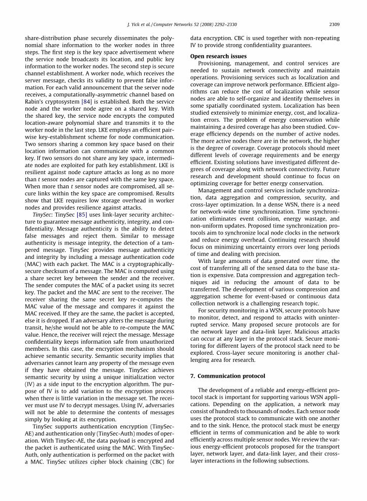
J. Yick et al. / Computer Networks 52 (2008) 2292–2330 2309
share-distribution phase securely disseminates the poly-nomial share information to the worker nodes in threesteps. The first step is the key space advertisement wherethe service node broadcasts its location, and public keyinformation to the worker nodes. The second step is securechannel establishment. A worker node, which receives theserver message, checks its validity to prevent false infor-mation. For each valid announcement that the server nodereceives, a computationally-asymmetric channel based onRabin’s cryptosystem [84] is established. Both the servicenode and the worker node agree on a shared key. Withthe shared key, the service node encrypts the computedlocation-aware polynomial share and transmits it to theworker node in the last step. LKE employs an efficient pair-wise key-establishment scheme for node communication.Two sensors sharing a common key space based on theirlocation information can communicate with a commonkey. If two sensors do not share any key space, intermedi-ate nodes are exploited for path key establishment. LKE isresilient against node capture attacks as long as no morethan t sensor nodes are captured with the same key space.When more than t sensor nodes are compromised, all se-cure links within the key space are compromised. Resultsshow that LKE requires low storage overhead in workernodes and provides resilience against attacks.
TinySec: TinySec [85] uses link-layer security architec-ture to guarantee message authenticity, integrity, and con-fidentiality. Message authenticity is the ability to detectfalse messages and reject them. Similar to messageauthenticity is message integrity, the detection of a tam-pered message. TinySec provides message authenticityand integrity by including a message authentication code(MAC) with each packet. The MAC is a cryptographically-secure checksum of a message. The MAC is computed usinga share secret key between the sender and the receiver.The sender computes the MAC of a packet using its secretkey. The packet and the MAC are sent to the receiver. Thereceiver sharing the same secret key re-computes theMAC value of the message and compares it against theMAC received. If they are the same, the packet is accepted,else it is dropped. If an adversary alters the message duringtransit, he/she would not be able to re-compute the MACvalue. Hence, the receiver will reject the message. Messageconfidentiality keeps information safe from unauthorizedmembers. In this case, the encryption mechanism shouldachieve semantic security. Semantic security implies thatadversaries cannot learn any property of the message evenif they have obtained the message. TinySec achievessemantic security by using a unique initialization vector(IV) as a side input to the encryption algorithm. The pur-pose of IV is to add variation to the encryption processwhen there is little variation in the message set. The recei-ver must use IV to decrypt messages. Using IV, adversarieswill not be able to determine the contents of messagessimply by looking at its encryption.
TinySec supports authentication encryption (TinySec-AE) and authentication only (TinySec-Auth) modes of oper-ation. With TinySec-AE, the data payload is encrypted andthe packet is authenticated using the MAC. With TinySec-Auth, only authentication is performed on the packet witha MAC. TinySec utilizes cipher block chaining (CBC) for
data encryption. CBC is used together with non-repeatingIV to provide strong confidentiality guarantees.
Open research issuesProvisioning, management, and control services are
needed to sustain network connectivity and maintainoperations. Provisioning services such as localization andcoverage can improve network performance. Efficient algo-rithms can reduce the cost of localization while sensornodes are able to self-organize and identify themselves insome spatially coordinated system. Localization has beenstudied extensively to minimize energy, cost, and localiza-tion errors. The problem of energy conservation whilemaintaining a desired coverage has also been studied. Cov-erage efficiency depends on the number of active nodes.The more active nodes there are in the network, the higheris the degree of coverage. Coverage protocols should meetdifferent levels of coverage requirements and be energyefficient. Existing solutions have investigated different de-grees of coverage along with network connectivity. Futureresearch and development should continue to focus onoptimizing coverage for better energy conservation.
Management and control services include synchroniza-tion, data aggregation and compression, security, andcross-layer optimization. In a dense WSN, there is a needfor network-wide time synchronization. Time synchroni-zation eliminates event collision, energy wastage, andnon-uniform updates. Proposed time synchronization pro-tocols aim to synchronize local node clocks in the networkand reduce energy overhead. Continuing research shouldfocus on minimizing uncertainty errors over long periodsof time and dealing with precision.
With large amounts of data generated over time, thecost of transferring all of the sensed data to the base sta-tion is expensive. Data compression and aggregation tech-niques aid in reducing the amount of data to betransferred. The development of various compression andaggregation scheme for event-based or continuous datacollection network is a challenging research topic.
For security monitoring in a WSN, secure protocols haveto monitor, detect, and respond to attacks with uninter-rupted service. Many proposed secure protocols are forthe network layer and data-link layer. Malicious attackscan occur at any layer in the protocol stack. Secure moni-toring for different layers of the protocol stack need to beexplored. Cross-layer secure monitoring is another chal-lenging area for research.
7. Communication protocol
The development of a reliable and energy-efficient pro-tocol stack is important for supporting various WSN appli-cations. Depending on the application, a network mayconsist of hundreds to thousands of nodes. Each sensor nodeuses the protocol stack to communicate with one anotherand to the sink. Hence, the protocol stack must be energyefficient in terms of communication and be able to workefficiently across multiple sensor nodes. We review the var-ious energy-efficient protocols proposed for the transportlayer, network layer, and data-link layer, and their cross-layer interactions in the following subsections.
2310 J. Yick et al. / Computer Networks 52 (2008) 2292–2330
7.1. Transport layer
The transport layer ensures the reliability and quality ofdata at the source and the sink. Transport layer protocols inWSNs should support multiple applications, variable reli-ability, packet-loss recovery, and congestion control mech-anism. The development of a transport layer protocolshould be generic and independent of the application. Itshould provide variable packet reliability for differentapplications. Each WSN application can tolerate differentlevels of packet loss. Packet loss may be due to bad radiocommunication, congestion, packet collision, full memorycapacity, and node failures. Any packet loss can result inwasted energy and degraded quality of service (QoS) indata delivery. Detection of packet loss and correctly recov-ering missing packets can improve throughput and energyexpenditure.
There are two approaches for packet recovery: hop-by-hop and end-to-end. Hop-by-hop retransmission requiresthat an intermediate node cache the packet informationin its memory. This method is more energy efficient sinceretransmission distance is shorter. For end-to-end retrans-mission, the source caches all the packet information andperforms retransmission when there is a packet loss.End-to-end retransmission allows for variable reliabilitywhereas hop-by-hop retransmission performs better whenreliability requirements are high.
A congestion control mechanism monitors and detectscongestion, thereby conserving energy. Before congestionoccurs, the source is notified to reduce its sending rate.Congestion control helps reduce retransmission and pre-vents sensor buffer overrun. As in packet-loss recovery,there are two approaches to congestion control: hop-by-hop and end-to-end. Hop-by-hop mechanism requiresevery node along the path to monitor buffer overflows.Hop-by-hop mechanism lessens congestion at a faster ratethan the end-to-end mechanism. When congestion is de-tected by a sensor node, all nodes along the path changetheir behaviour. End-to-end mechanism relies on the endnodes to detect congestion. Congestion is flagged whentimeout or redundant acknowledgements are received.
There are tradeoffs between hop-by-hop and end-to-end approaches for packet-loss recovery and congestioncontrol mechanism. Depending on the type, reliability,and time-sensitivity of the application, one approach maybe better than the other. Existing transport layer protocolsin WSNs attempt to address the above design issues.
Sensor transmission control protocol (STCP): STCP [86] isa reliable transport layer protocol that provides variablereliability, congestion detection and avoidance, and sup-port of multiple applications in the same network. Func-tionalities of STCP are executed at the base station. Thebase station is assumed to have high processing capability,storage, and power to communicate with all the nodes inthe network.
A source node must transmit a single session initiationpacket to the base station before sending data. The sessioninitiation packet contains information about the number offlows from the node, the type of data flow, transmissionrate, and required reliability. The sensor node must waitfor an acknowledgement from the base station before
transmitting data. For continuous data flows, the base sta-tion estimates the time of arrival of each packet from eachsource. If a packet is not received by the base station with-in a given period of time, the base station determineswhether the current required reliability is met. Reliabilityis a measure of the fraction of packets that are successfullyreceived. If current reliability goes below the required le-vel, the base station sends out a negative acknowledge-ment (NACK) to the source node for retransmission. Eachsource node stores its transmitted packets in a buffer.When the buffer reaches a threshold, it is cleared.
For event-driven flows, the source node computes thereliability of the packet reaching the base station. If thecomputed value is more than the required reliability, thenode will not buffer the packet to save storage space.The base station sends out positive acknowledgement(ACK) for each packet received from a source node. Whenan ACK reaches the source node, the corresponding trans-mitted packet is deleted from the buffer. Every sensor nodemaintains two thresholds in its buffer: low and highthresholds. When the buffer reaches the lower threshold,the congestion bit is set with a certain probability. Oncethe buffer reaches the higher threshold, the congestionbit is set for all packets. The congestion bit is a flag inform-ing the base station to either notify the source to reduce itstransmission rate or re-route packets along a differentpath.
Price-oriented reliable transport protocol (PORT): PORT[87] minimizes energy consumption, achieves the neces-sary level of reliability, and provides a congestion-avoid-ance mechanism. PORT minimizes energy consumed byavoiding high communication cost. End-to-end communi-cation cost is the measure of the amount of energyconsumed to deliver a packet from the source to the basestation (sink). To achieve the necessary level of reliabilityand minimize energy, the source’s reporting rate isdynamically adjusted in a bias manner. PORT provides anin-network congestion mechanism to alleviate trafficdynamically.
PORT differs from other transport protocols in that itsview of reliability is not a ratio of the total incoming packetrate to the desire incoming rate, but the assurance that thesink obtains enough information on the phenomenon ofinterest. When a phenomenon of interest occurs, nodescloser to the phenomenon will contain more informationand less error. PORT adapts bias packet reporting rate ofthe sensor nodes to increase the sink’s information regard-ing the phenomenon. PORT provides two mechanisms thatensure this reliability. The first is a dynamic source reportrate feedback mechanism to allow the sink to adjust thereporting rate of each data source. Each packet sent bythe source is encapsulated with its node price. Node priceis the total number of transmission attempts made before asuccessful packet is delivered from the source to the sink. Itis a metric used to evaluate the energy cost of the commu-nication. The sink adjusts the reporting rate of each sourcebased on the source’s node price and the information pro-vided about the physical phenomenon. Feedback from thesink is sent to the sources along the reverse path. The sec-ond mechanism provides the sink with end-to-end com-munication cost information from the source to the sink.

J. Yick et al. / Computer Networks 52 (2008) 2292–2330 2311
End-to-end communication cost is used to alleviate con-gestion. When congestion occurs, communication cost in-creases with respect to packet loss. The sink uses thecommunication cost information to slow down the report-ing rate of the appropriate source and increase the report-ing rate of other sources that have lower communicationcost since reliability must be maintained.
GARUDA: GARUDA [88] is a reliable downstream datadelivery transport protocol for WSNs. It addresses theproblem of reliable data transfer from the sink to the sen-sors. Reliability is defined in four categories: (1) guaranteedelivery to the entire field, (2) guarantee delivery to a sub-region of sensors, (3) guarantee delivery to a minimal set ofsensors to cover the sensing region, and (4) guaranteedelivery to a probabilistic subset of sensors.
GARUDA’s design is a loss-recovery core infrastructureand a two-stage NACK-based recovery process. The coreinfrastructure is constructed using the first packet deliverymethod. The first packet delivery method guarantees firstpacket delivery using a Wait-for-First-Packet (WFP) pulse.WFP pulse is a small finite series of short duration pulsessent periodically by the sink. Sensor nodes within thetransmission range of the sink will receive this pulse andwait for the transmission of the first packet. The first pack-et delivery determines the hop-count from the sink to thenode. Nodes along the path can become candidates for thecore. A core candidate elects itself to be a core node if it hasnot heard from neighboring core nodes. In this manner, allcore nodes are elected in the network. An elected core nodemust then connect itself to at least one upstream corenode.
GARUDA uses an out-of-order forwarding strategy toovercome the problem of under-utilization in the eventof packet losses. Out-of-order forwarding allows subse-quent packet to be forwarded even when a packet is lost.GARUDA uses a two-stage loss-recovery process. The firststage involves core nodes recovering the packet. When acore node receives an out-of-sequence packet, it sends arequest to an upstream core node notifying that there aremissing packets. The upstream core node receiving thatmessage will respond with a unicast retransmission ofthe available requested packet. The second stage is thenon-core recovery phase, which involves non-core nodesrequesting retransmission from the core nodes. A non-corenode listens on all retransmissions from its core node andwaits for completion before sending its own retransmis-sion request.
Delay sensitive transport (DST): DST protocol [89] ad-dresses the issue of congestion control, reliability, andtimely packet delivery. DST has two components: a reliableevent transport mechanism and a real-time event trans-port mechanism. Reliable event transport mechanismmeasures the observed delay-constrained event reliabilityagainst the desired delay-constrained event reliability todetermine if appropriate action is needed to ensure the de-sire reliability level for event-to-sink communication. Theobserved delay-constrained event reliability is defined asthe number of packet received within a certain delaybound at the sink over a specified interval. The desired de-lay-constrained event reliability is the minimum numberof data packets required for the event to be a reliable
detection. If the observed delay-constrained event reliabil-ity is greater than the desire delay-constrained event reli-ability, the event is considered to be reliable. Otherwise,the report rate of the sensors must be increased to assurethat the desired reliability level is met. DST also assuresreliable and timely event detection within the event-to-sink delay bound. The real-time event transport mecha-nism uses this event-to-sink delay bound delay to achievethe application specific objectives. The event-to-sink delayis a measure of the event transport delay and event processdelay. Event transport delay is the time between the eventoccurring and when the sink receives it. Event process de-lay is the processing delay at the sink. For congestiondetection, DST measures buffer overflow at each nodeand computes the average node delay. Upon congestion,sensor nodes inform the sink of the congestion situation.The sink in response would adjust the reporting rate ofthe sensors. Simulation experiments show that DSTachieves reliability and timely event detection with mini-mum energy consumption and latency.
Pump slowly, fetch quickly (PSFQ): PSFQ [90] is a reliabletransport protocol that is scalable and robust. The goals ofPSFQ are to guarantee data segment delivery, minimize thenumber of transmission for lost detection and data recov-ery operation, to operate in harsh environments, and toprovide a loose delay bound for data delivery. PSFQ oper-ates in three functions: pump operation, fetch operation,and report operation. The pump operation controls the rateat which data packets are passed along into the network.The pump operation is based on a simple schedulingscheme which used two timers, Tmin and Tmax. A node mustwait at least Tmin before transmitting a packet. By waitingat least Tmin, a node is given the opportunity to recovermissing packets and reduce redundant broadcasts. Tmax isused as a loose upper delay bound for when all packetsshould be received. The fetch operation is called whenthere is a gap in the sequence number between the packetsreceived. The fetch operation requests a retransmission ofthe lost packet from the neighboring nodes. If multiplepackets are lost in a bursty event, a single fetch would besent to retrieve the packets. Lastly, the report operationprovides a feedback status to the users. A status reportmessage travels from the farthest target node in the net-work to the requesting user. Along the path, each node ap-pends its report message in an aggregated manner into theoriginal message. Results show that PSFQ outperforms theidealized scalable reliable multi-cast (SRM-I) [5] in termsof tolerance, communication overhead, and deliverylatency.
Event-to-sink reliable transport (ESRT): ESRT protocol[91] is developed for reliable event detection with mini-mum energy expenditure. ESRT uses a congestion controlmechanism to reduce energy consumption while main-taining the desired reliability level at the sink. ESRT algo-rithm is run mainly at the sink. The sink computes thereliability factor and reporting frequency at each interval.The reliability factor is a measure of the data packets re-ceived from the source nodes to the sink. The computedreliability factor is compared against an application-de-fined desired reliability. If the computed reliability is great-er than the desired reliability, ESRT would reduce the

2312 J. Yick et al. / Computer Networks 52 (2008) 2292–2330
reporting frequency of the source nodes. If the computedreliability is lower than the desired reliability, ESRT wouldincrease the reporting frequency of the source nodes toachieve the desired reliability. At each interval, the sinkbroadcasts the new reporting frequency to source nodesin the network. Upon receiving the information, sourcenodes adjust their reporting rate. In ESRT, the congestioncontrol mechanism is based on monitoring the routing buf-fer of each sensor nodes. A sensor node whose buffer over-flows is an indication of congestion. Upon experiencingcongestion, the sensor node sets the congestion notifica-tion bit flag in its outgoing packets. The sink receivingthese packets along with the computed reliability factordetermines the state of the network and acts accordingly.Simulation results show that ESRT is able to attain the de-sired reliability level with minimum energy expenditureunder different network states with random and dynamictopologies.
Congestion detection and avoidance (CODA): CODA [92] isan energy-efficient congestion control scheme that canquickly mitigate congestion, once detected. CODA hasthree components: congestion detection, hop-by-hopbackpressure, and multi-source regulation. CODA detectscongestion by monitoring buffer occupancy and measuringchannel load. Monitoring of the buffer size requires only asmall amount of overhead and processing. When bufferoccupancy is high, sensors listen to the local channel loadconditions to detect congestion. Once congestion is de-tected, the sensor node broadcasts a suppression messageto its neighbors and makes adjustment to prevent conges-tion downstream. It also broadcasts a backpressure mes-sage upstream to the source. Each upstream nodereceiving the backpressure message determines whetheror not to propagate the message. Depending on the conges-tion policy, a node can prevent further congestion build upby dropping the incoming data packets or adjust theirsending rate. In the event of a persistent congestion, CODA
Table 1Comparison of transport layer protocols for WSNs
STCP PORT GARUDA
Congestion Congestioncontrol
Yes Yes No
Congestiondetection
Buffer size Node price andlink-loss rates
–
Congestionmitigation
Traffic redirectionor end-to-end rateadjustment
Traffic redirectionor end-to-end rateadjustment
–
Reliability Direction Sensor to sink Sensor to sink Sink tosensor
Reliabilitymeasure
Packet reliability Event informationreliability
Packet adestinatireliabilit
End-to-end/Hop-by-hop
End-to-end – Hop-by-
Packetrecovery
Yes No Yes
Cache Yes – YesACK/NACK ACK, NACK – NACK
Energy conservation Yes Yes Yes
uses a closed-loop multi-source regulation method to as-sert congestion control over multiple sources from thesink. When the source node event rate is less than somefraction of the maximum theoretical throughput of thechannel, the source regulates its own rate. Upon exceedingthis value, the source node is most likely to be contributingto congestion. In this case, the source enters sink regula-tion. The sink sends a message to the source with a pre-de-fined event rate that the sink computed. When congestionis relieved, the sensor node would then regulate itselfagain without the sink. Results show that CODA canimprovement performance and reduce energy usage.
Open research issuesThe main goal of a transport layer protocol in a WSN is
to achieve reliable data transport by inspecting the net-work state for congestion and reliability. Table 1 summa-rizes and compares the transport protocols reviewed.STCP, DST, ESRT and PORT address the problem of conges-tion control and reliability guarantee from the sensors tothe sink while GARUDA and PSFQ examine only the prob-lem of reliability from the sink to the sensors. STCP, GARU-DA, and PSFQ incorporate packet recovery. STCP providesend-to-end reliability guarantee and uses ACK/NACK forloss detection and notification. PORT also provides end-to-end reliability guarantee but does not recover lost pack-ets. GARUDA, however, uses hop-by-hop reliability guaran-tee and NACKs for packet recovery.
Although many transport layer protocols have beenproposed for WSNs, there are still several open researchproblems such as cross-layer optimization, fairness, andcongestion control with active queue management. Thetransport layer can benefit from cross-layer interactions.Cross-layer interactions can improve the performance ofthe transport protocol by selecting better paths for re-transmission and getting error reports from the link layer.There is some research in this area; however, cross-layer
CODA DST PSFQ ESRT
Yes Yes No Yes
buffer size andchannel load
Buffer size andaverage nodedelay calculation
– Buffer size
Drop packets oradjust sending rateat each node
End-to-end rateadjustment
– End-to-endrateadjustment
Sensor to sink Sensor to sink Sensor tosink
Sensor tosink
ndony
– Event reliability Packetreliability
Eventreliability
hop – End-to-end Hop-by-hop
End-to-end
– No Yes No
– – Yes –ACK – NACK –
Yes Yes – Yes

J. Yick et al. / Computer Networks 52 (2008) 2292–2330 2313
optimization across multiple layers needs to be exploredmore. Current congestion control mechanisms focus onmonitoring of the channels and dynamically adjustingthe data rate of the source when congestion occurs. Thereis no active monitoring of the queue to avoid congestion.Incorporating active queue management with congestioncontrol may further reduce packet loss and increasethroughput. The transport protocol should guarantee fair-ness among sensor nodes. One solution to this problem isto assign packets with priority. The problem of guarantee-ing fairness in a frequently-changing topology has notbeen extensively explored.
7.2. Network layer
The network layer handles routing of data across thenetwork from the source to the destination. Routing pro-tocols in WSNs differs from traditional routing protocolsin several ways. For one, sensor nodes do not have Inter-net protocol (IP) addresses, so IP-based routing protocolscannot be used in a WSN. The design of network proto-cols in a WSN needs to be scalable. It should easily man-age communication among many nodes and propagatesensor data to the base station. The protocol should meetnetwork resource constraints such as limited energy,communication bandwidth, memory, and computationcapabilities. By meeting these constraints, a sensor net-work’s lifetime can be prolonged. Lastly, the protocolshould address issues of efficiency, fault tolerance, fair-ness, and security. A few representative approaches aredescribed below.
Geographical routing: Geographical routing [93] uses agreedy forwarding mechanism to forward a packet fromthe source to the destination. This approach forwardspacket by choosing neighbors which are closest to the des-tination. It assumes that the network is sufficiently dense,nodes know their own location and their neighbors’ loca-tions, and multi-hop forwarding is reliable.
Several novel forwarding strategies are proposed to im-prove the performance of geographic routing. These for-warding strategies can be divided into two categories:distance-based and reception-based. For distance-basedforwarding, a node only knows the distance of its neigh-bors while in reception-based forwarding the packetreception rates of its neighbors are also known. Distance-based forwarding consists of the original greedy forward-ing and distanced-based blacklisting. In original greedyforwarding, each node forwards packets to the neighborclosest to the destination based on a minimum receptionrate. A minimum reception rate must be met before twonodes can become neighbors. Original greedy forwardingselects neighbors with highest distance, independent ofthe reception rate. In distance-based blacklisting, eachnode blacklists neighbors that are above a certain distancethreshold from itself. The blacklist distance threshold is setas a fraction of a nominal radio range. Packets are for-warded to the neighbor closest to the destination fromthose neighbors at a distance less than the threshold fromthe current forwarding node.
Four reception-based forwarding schemes areproposed:
1. Absolute reception-based blacklisting: Each node black-lists all neighbors that have a reception rate below acertain threshold. Only neighbors closest to the destina-tion with a reception rate above the threshold willreceive the packet for forwarding.
2. Relative reception-based blacklisting: A node blacklists adifferent set of neighbors for each new destination.Blacklisting of neighbors depend on the node’s rankingwithin a set of neighbors. A node’s ranking depends onits distance to the destination and the reception rate.Relative reception-based blacklisting prevents allneighbors to be blacklisted as in absolute reception-based blacklisting.
3. Best reception neighbor: Best reception neighbor for-wards packets to neighbors with the highest receptionrate from the neighbors that are closer to thedestination.
4. Best reception rate and distance: Best reception rate anddistance is based on the product of the reception rateand the distance. The node computes this product valuefor all neighbors that are close to the destination. Theneighbor with the highest product value will be chosen.
Results show that reception-based forwarding strate-gies are more efficient than distance-based strategies. Rel-ative reception-based blacklisting achieves higher deliveryrates than absolute reception-based blacklisting. Overall,the new geographical forwarding strategies are better interms of energy and minimizing route disconnection thanthe original greedy forwarding approach.
Anchor location service (ALS): ALS protocol [94] is a grid-based protocol that supports location-based routing be-tween multiple moving sources and destinations. Thesources and destinations are all sensor nodes in the net-work. ALS first constructs a predefined geographical gridstructure for the network. Before deployment, each sensornode contains information regarding the size of each gridcell and the base line coordinates. Sensor nodes are ran-domly deployed and they obtain their own location usingan existing positioning mechanism, e.g., GPS. Knowing itslocation, the sensor determines which grid square it fallsinto and decides whether it will become a grid node. Sen-sors that become grid nodes establish connections withneighboring grid nodes.
Multiple destination nodes may exist in the network.Each destination node selects a nearby grid node to be itssink agent. The sink agent is responsible for distributinglocation information of the destination node using an an-chor system. The anchor system is made up of a set of gridnodes, called anchors, which act as location servers. Whenan event occurs, a sensor node becomes a source node thattransmits data to a destination node. The source node firstregisters itself to the nearest grid node that becomes thesource agent. The source agent queries the anchor systemto locate the destination node and reports the informationto the source node. Upon receiving the sink agent’s infor-mation, the source sends data packets to the sink agentusing a location-based routing protocol.
Secure routing (SecRout): SecRout protocol [95] guaran-tees secure packet delivery from the source to the sink.SecRout employs a two-level cluster-based approach to se-

2314 J. Yick et al. / Computer Networks 52 (2008) 2292–2330
cure the network. The lower level contains sensors or clus-ter members while the upper level contains cluster heads.In the self-organization phase, sensor nodes are dividedinto clusters. Each cluster contains a cluster head. Sensornodes communicate to the sink (or base station) via clusterheads. Data is first sent from the sensors to the clusterhead. The cluster head aggregates the data from its mem-bers and sends it to the sink (or base station).
For secure packet delivery, SecRout uses symmetriccryptography to secure packets along the path. Each sensornode is given a unique identity (ID) and a preloaded key(KEY). The ID identifies the node and the KEY is used tosecure messages sent to the sink. The sink is assumed tobe a high power node with high memory and computationcapability. The sink also knows about network topologyand all sensor node information. A table containing eachnode’s ID and KEY pair is maintained by the sink. It isassumed that the sink cannot be compromised and canbe trusted.
Secure data transfer starts with a sensor node encrypt-ing its data packet using a cluster key. The cluster key isgenerated by the cluster head during the self-organizingphase and is shared among sensor nodes within the clus-ter. Upon receiving the encrypted information, the clusterhead verifies the data using its cluster key. If the verifica-tion succeeds, the cluster head will decrypt the data. Thecluster head collects data from all its members and thenaggregates the data to form a new data packet. The newdata packet will be encrypted with the cluster head’s pre-loaded key and sent to the sink via multi-hop routing. Thesink receiving the packet again verifies the authenticity ofthe packet. If verification succeeds, it will decrypt the pack-et and store the information.
SecRout guarantees that packets will reach the sinkeven if malicious nodes exist in the route. Routing packetsand data packets contain only partial path informationsuch as the next-hop neighbor. Each sensor node maintainsa routing table containing partial routing path (previousand next node) to the sink. When a node is compromised,it will not be able to obtain information about the tra-versed intermediate nodes. SecRout provides route main-tenance to update the routing table and trigger newroute discovery when it detects a malicious node.
Secure cell relay (SCR): SCR [96] routing protocol is de-signed to provide resistance against security attacks. SCRis a cluster-based algorithm where nodes form a cluster(cell) based on their locations. SCR differs from other clus-ter-based algorithm in that there is no cluster head elec-tion. An active node becomes the relay node (clusterhead) based on its remaining energy. In SCR, the entire net-work is divided into equal-sized square cells. Each sensor isstatically aware of its own location and that of the base sta-tions. It is assumed that the base stations can be trustedwhile sensors can be compromised.
Before deployment, each sensor node and the base sta-tion share a common global key, KG, used for initial neigh-bor discovery and handshake phase communication. It isassumed that, before deployment, all sensor nodes andthe base station are synchronized. SCR uses symmetricencryption to secure packets. After deployment, the basestation encrypts its location information with KG and
floods it to all sensor nodes. In the neighbor discoveryphase, sensor nodes discover their neighbors via a three-way handshake protocol, which establishes the sharedsecret keys between neighbor nodes. After establishing atable of shared secret keys of all neighbors, each sensornode destroys KG and uses the shared secret key for futurecommunication with its neighbors.
Based on the location of the source and the sink, a rout-ing path is formed through a series of cells in the directionfrom source to sink. SCR routing provides two or morebackup paths determined by the source. When an adver-sary attacks a node, the backup paths will be used to for-ward packets. SCR provides defence against the followingattacks: Sybil, wormhole and sinkhole, selective forward-ing, and hello flood. In Sybil attack, the adversary can pre-tend to be a node. Since shared keys are known onlybetween the neighboring nodes, the attack will fail. Inwormhole and sinkhole attack, an adversary can broadcasta new route, tunnel, or fake link to the base station. Nodesthat receive this new route will not use it because theyroute only through the routing cell path. In selective for-warding, the adversary pretends to be a relay node in a celland drops some packets while forwarding others. To pre-vent this attack, a node in a cell can only become a relaynode for a user-defined number of times. After this num-ber, the source will have to set up another path to routearound this node. In addition, the sink will be notified thatthe current relay node will no longer be a relay node. Inhello flood attack, the adversary node tries to establish aunidirectional link with a sensor node. This will not worksince a sensor node uses three-way handshake to establishits neighbors and the shared secret keys.
Open research issuesMany routing protocols have been proposed for routing
data in sensor networks. Table 2 summaries the character-istics of routing protocols covered in this survey. Importantconsiderations for these routing protocols are energy effi-ciency and traffic flows. In this review, two categories ofrouting approaches are explored: location-based routingand cluster-based routing. Location-based routing consid-ers node location to route data. Cluster-based routing em-ploys cluster heads to do data aggregation and relay theinformation to the base station. A comparison of securityrouting protocol is also included in the table. A securityrouting protocol strives to meet security requirements toguarantee secure delivery of the data from the source tothe destination.
Future research issues should address security, QoS, andnode mobility. Experimental studies regarding security ap-plied to different routing protocols in WSNs should beexamined. There is little research in QoS routing in sensornetworks. QoS guarantees end-to-end delay and energy-efficient routing. In applications where sensor nodes aremobile, new routing protocols are needed to handle fre-quent topology changes and reliable delivery.
7.3. Data-link layer
The data-link layer is concerned with the data transferbetween two nodes that share the same link. Since the

Table 2Comparison of network layer protocols for WSNs
Description Geographical routing ALS SecRout SCR
Routing type Location-based Location-based Cluster-based Cluster-basedScalability Fair Good Good GoodSynchronization No No Yes YesData cache No No Yes –Data aggregation No No Yes YesComputation overhead Neighbor selection/
blacklistingEach anchor processes sinklocation information
Data aggregation, encryptingand decrypting packets
Encrypting and decryptingpackets
Communication Overhead Neighbor discovery Network and anchor systemsetup, and sink query process
Setup and maintaining clusters Setup cells, neighbor discoveryand three-way handshake
Data security No No Yes YesEnergy requirement Not specified Not specified High power base station High power base station
J. Yick et al. / Computer Networks 52 (2008) 2292–2330 2315
underlying network is wireless, for effective data transfer,there is a need for medium access control and manage-ment. The MAC protocol design should have the followingattributes: energy efficiency, scalable to node density,frame synchronization, fairness, bandwidth utilization,flow control, and error control for data communication.
Error detection and correction services are offered atthe data-link layer as well as the transport layer. One ofthe widely used error-detection technique is cyclic redun-dancy check (CRC) [97]. CRC operates as follows in WSN.The sender and receiver must first agree on a fixed datablock size before transmission. The sender splits a packetfrom the network layer into data blocks which will be reas-sembled at the receiver. An 8-bit CRC can be used for errordetection. The blocks containing the data and the CRC bitsare packaged into a frame. Each frame is sent to the recei-ver. Upon receiving the frame, the receiver identifieswhether the data block contains error. If there are errorblocks, the receiver will initiate the recovery process to re-trieve those error blocks after receiving a certain numberof frames.
Recovery techniques in WSN include automatic repeatrequest (ARQ) [97], forward error correction (FEC) [98], hy-brid ARQ (HARQ) [99], simple packet combining (SPaC)[100], and multi-radio diversity (MRD) [101]. ARQ usesacknowledgement and timeout to provide explicit feed-back to the sender. The feedback can be in the form of a po-sitive acknowledgement (ACK) or a negativeacknowledgement (NACK). The sender receiving a NACKor timing out will retransmit the data frame. A limitationto ARQ is that it is limited to frame error detection. An en-tire frame has to be retransmitted if there is a single bit er-ror. FEC, on the other hand, decreases the number ofretransmissions. The sender adds some more amount ofredundant data into each message so that the receivercan detect and correct errors. The advantage of FEC is thatretransmission is reduced and the wait time for sending anacknowledgement and retransmitting the data can beavoided. Hybrid ARQ is a variation of the ARQ method. Inhybrid ARQ, both ARQ and FEC are combined. There aretwo types of Hybrid ARQ schemes: type-I and type-II.Type-I includes both the error detection and error correc-tion bits in every transmission packet and using a correc-tion code to correct error. Type-II transmits either theerror detection bits or the FEC information along withthe data. If an error is detected in the first packet, it will
wait for the second packet which contains the FEC paritiesand error detection to correct the error. If errors still exist,the packets are combined to error correct itself. SPaC andMRD perform error correction by combining corruptedpackets and using HARQ. SPaC buffers corrupted packetat the receiver and waits for retransmission. Rather thanretransmitting the original packet, the sender transmitsparity bits. Upon receiving the retransmission packet, thereceiver performs packet combining to recover the errors.MRD uses two techniques to recover from error. The firsttechnique is frame combining with multiple erroneousframes together in the attempt to avoid re-transmission.The second technique is the request-for-acknowledgement(RFA) scheme to recover the packet.
The design of the MAC protocol in a WSN is subject tovarious constraints such as energy, topology, and networkchanges. Minimizing energy to extend the network life-time is its primary goal. The design of the MAC protocolshould prevent energy wastage due to packet collisions,overhearing, excessive retransmissions, control overheads,and idle listening. It should also adapt to topology and net-work changes efficiently. A wide range of MAC protocolshave been proposed to achieve high channel utilization,collision avoidance, and energy efficiency. We review someof the representative approaches below.
TRAMA: Ref. [102] proposed a TRaffic-Adaptive MediumAccess protocol (TRAMA) to increase channel utilization inan energy-efficient manner. TRAMA attains energy effi-ciency by avoiding collisions and switching to an idle statewhen there are no transmissions. To avoid collisions, TRA-MA adapts its transmission schedule according to trafficinformation patterns. TRAMA assumes a single, time-slot-ted channel for data and control signal transmissions. Timeis divided into sections of random-access and scheduled-access periods. TRAMA supports unicast, multi-cast, andbroadcast traffic.
TRAMA consist of three components: (1) Neighbor Pro-tocol (NP), (2) Schedule Exchange Protocol (SEP), and (3)Adaptive Election Algorithm (AEA). In TRAMA, nodes startin random-access mode where each node transmits at ran-dom slots. Nodes can join the network at random accessperiods. During this period, NP sends out small signallingpackets to gather neighbor updates. If there are no updates,signalling packets are sent as keep-alive beacons. The sig-nalling packets are used to maintain connectivity betweenneighbors. A node deletes a neighbor node from its table if

2316 J. Yick et al. / Computer Networks 52 (2008) 2292–2330
it does not hear from the neighbor within a certain periodof time.
The second component, SEP, sets up the traffic-basedschedule. The schedule captures the traffic window forwhich the node can transmit. During scheduled-accessperiod, the node periodically broadcasts its schedule infor-mation to its one-hop neighbors. Each node generates aschedule by computing the schedule interval. The scheduleinterval represents the number of slots that the node canannounce its schedule information to the neighbors. Theschedule is sent along with every data packet. The Change-Over slot is the last slot in the current schedule interval. Allnodes listen during the ChangeOver slot to synchronizetheir schedule.
The last component, AEA, determines the state of thenode. For energy efficiency, nodes are switched to sleepmost of the time. A TRAMA node determines the currentstate (transmit, receive, or sleep) that it should be in basedon the node’s priority within the two-hop neighbor and theone-hop neighbor schedules. A node computes its priorityvalue using a pseudo-random hash function during eachtime slot. Both priority and schedule information are usedto determine if a node will become a transmitter or recei-ver for that time slot while others will switch into sleepmode. Nodes selected to transmit can give up their slotsfor re-use if they do not have data to send.
TRAMA guarantees delivery and energy efficiency withthe expense of packet delays. It achieves high throughputand avoids collision.
B-MAC protocol: Unlike TRAMA, the Berkeley media ac-cess control (B-MAC) [103] is a reconfigurable carrier-sense multiple access (CSMA) protocol that achieves lowpower processing, collision avoidance, and high channelutilization. B-MAC optimizes system performance byemploying an adaptive preamble sampling scheme. A setof adaptive bi-directional interfaces is used to reconfigurethe protocol based on the network load.
B-MAC contains the following functionality: clear chan-nel assessment (CCA) and packet back off, link-layeracknowledgement, and low power listening (LPL). For col-lision avoidance, B-MAC utilizes CCA to determine if thechannel is clear. CCA is an outlier algorithm that searchesfor outliers in the received sample signals. An outlier existsif the channel energy is significantly below the noise floor.During the channel sampling period, if an outlier is found,the channel is clear, else the channel is busy. In case of abusy channel, packet backoff is used. Backoff time is eitherinitially defined or randomly chosen.
B-MAC supports link-layer acknowledgement for uni-cast packets. When the receiver receives a packet, anacknowledgement packet is sent to the sender. To reducepower consumption, B-MAC employs an adaptive pream-ble sampling scheme called LPL. LPL performs periodicchannel sampling by cycling through awake and sleepperiods. In the awake period, the node’s radio is turnedon to check for activities in the channel using CCA. If activ-ities are detected, it will remain awake to receive theincoming packet. Once it receives the packet, it will go backto sleep. Idle listening occurs when the node is awake butthere is no activity in the channel. A timeout will force thenode to go back to sleep.
All B-MAC functionality such as acknowledgements,CCA, and backoff can be changed through a set of adaptivebi-directional interfaces. By enabling or disabling B-MACfunctionality, the throughput and energy consumption ofa node can change.
Z-MAC protocol: In comparison to B-MAC, Z-MAC [100] isa hybrid MAC protocol that combines the strength of theTDMA and CSMA while offsetting their weaknesses. Z-MACachieves high channel utilization and low latency underhigh contention. It reduces collisions between two-hopneighbors at a low cost. Z-MAC is robust to dynamic topol-ogy changes and time synchronization failures which com-monly occur in the network. Z-MAC uses CSMA as thebaseline MAC scheme and a TDMA schedule to enhance con-tention resolution. This design results in high initial over-head which is amortized over a long period of networkoperation and eventually improves the throughput and en-ergy efficiency. The protocol uses an efficient and scalablechannel scheduling algorithm for channel re-use and slotassignment. Unlike TDMA, a node may transmit during anytime slot. It will always perform carrier sensing and transmita packet when the channel is clear. An owner of the slot willhave higher priority over non-owners to access the channel.The goal is to allow the re-use of a slot when the slot owner isnot transmitting data. By mixing CSMA and TDMA, Z-MACbecomes more robust to timing failures, time-varying chan-nel conditions, slot-assignment failures, and topologychanges. Performance results show that Z-MAC is betterthan B-MAC under medium to high contention. Under lowcontention, B-MAC is slightly better in terms of energy.
Low power reservation-based MAC protocol: The lowpower reservation-based MAC protocol [104] addressesthe issue of energy conservation and adaptation to traffic.To address the issue of energy conservation, the reserva-tion-based MAC protocol uses a clustered hierarchical net-work and a TDMA-like frame structure. In a clusteredhierarchy network, nodes organize themselves into clus-ters and contend for the role of cluster head in each cluster.Cluster head nodes are responsible for synchronizing allthe nodes in their cluster to a TDMA schedule. TheTDMA-like frame structure has contention-based slot res-ervation, schedule establishment, and slotted data trans-mission. Unlike traditional TDMA with fixed frame size,the protocol adapts the TDMA frame size according tothe probability of successful data transmission. Accordingto the protocol, the cluster head increases the frame sizeif the number of failures exceeds a predetermined value.On the contrary, if the number of failure is small, it will de-crease the frame size. By adapting the frame size, the prob-ability of success of packet transmission is increased.Nodes are able to effectively transmit at a higher data rateas a result of increasing throughput. In terms of energy dis-sipation, adaptive frame size shows significant energy sav-ings due to less collisions and high probability of success.
Low power distributed MAC protocol: [105] presents alow power distributed MAC protocol which combinesCSMA/CA and multi-channel spread spectrum techniques.For a given frequency band, the band is partition into mul-tiple channels. A channel and code is assigned to each nodein the network. The channel and code assigned must be un-ique across each node’s two-hop neighbors. The primary

J. Yick et al. / Computer Networks 52 (2008) 2292–2330 2317
goal is to avoid collisions and minimize energy wastage.The protocol also incorporates a new wake up radio oper-ation to save energy. Two radios are used, a low powerwake-up radio and a normal data radio. The low powerradio monitors the network and triggers the normal radioto wake up when there is data to transmit or receive. Thenormal radio switches between active and sleep modes.Results show that energy consumption for channel moni-toring is almost negligible and average energy consump-tion is significantly reduced.
Spatial correlation-based collaborative MAC (CC-MAC):CC-MAC protocol [106] exploits the spatial correlation ofthe data at the MAC layer to regulate and prevent redundanttransmissions. CC-MAC has two components: event MAC(E-MAC) and network MAC (N-MAC). E-MAC filters outthe correlated data packets while N-MAC prioritizes therouting packets. CC-MAC protocol is implemented into eachsensor node. In a WSN, the E-MAC protocol forms correla-tion regions to filter out correlated event information. Ineach region, a single representative sensor node is selectedto transmit its data while all other sensor nodes back off fora specified period. At the end of each period, all nodes in thatregion except the representative sensor node go into a con-tention phase to get elected as the new representative. WithE-MAC protocol filtering out correlated packets, the N-MACprotocol routes the packet to the sink using a priority-basedmethod. Route-through packets are given higher prece-dence over newly-generated packets. Routing nodes use abackoff procedure to avoid collisions between multipleroute-through packets transmitting at the same time. Interms of performance, CC-MAC protocol shows significantsavings in energy, latency, and packet drop rate.
Open research issuesTable 3 compares the MAC protocols reviewed above.
Both TRAMA and Z-MAC require a random access period
Table 3Overview of a representative set of link-layer protocols
Attributes TRAMA B-MAC Z-MAC LowresMA
Channel accessmode
Time-slottedrandom andscheduledaccess
Clear channelassessment(CCA)
Time-slottedrandom andscheduledaccess
Timconbas
Timesynchronization
Yes No Yes Yes
Protocol type TDMA/CSMA CSMA TDMA/CSMA TDProtocol specifics Achieves
adequatethroughput andfairnessthroughtransmitter-electionalgorithm andchannel re-use
Bi-directionalinterface forreconfigurationof systemservices tooptimizeperformance
Exploits thestrengths ofTDMA and CSMAwhileoffsetting theirweaknesses
Incprooftraadatotodat
Energyconservation
Schedule sleepintervals andturn radio offwhen idle,collisionavoidancescheduling
Low powerlistening (LPL)time for energyefficiency
Low powerlistening (LPL)time for energyefficiency
Nowaass
and a schedule exchange period. In addition, time synchro-nization must be achieved in the network. In comparisonwith other contention-based protocols, TRAMA has higherdelay and is suited for applications that are not time sensi-tive. B-MAC and Z-MAC both adapt well to topology changeswhile TRAMA does not. B-MAC has higher throughput un-der low contention environment while Z-MAC performsbetter in high contention environments. Low power reser-vation-based MAC, low power distributed MAC, and TRAMAminimize energy with sleep cycles when nodes do not havedata to transmit or receive. CC-MAC, on the other hand, fil-ters correlated information and prioritizes packets.
Although various MAC protocols have been proposed,there is possible future work for system performance opti-mization. Cross-layer optimization is an area that needs tobe explored more extensively. Cross-layer interaction canreduce packet overhead on each of the layers, therebyreducing energy consumption. Interaction with the MAClayer can provide other layers with congestion controlinformation and enhance route selection. Many existingMAC protocols address performance studies of static sen-sor nodes, but there is still a lack of literature for compar-ing these protocols in a mobile network. By enhancing theMAC protocol, one can significantly improve communica-tion reliability and energy efficiency.
7.4. Physical layer
The physical layer provides an interface for transmittingbit streams over the physical-communication medium. It isresponsible for interacting with the MAC layer, performingtransmission and reception, and modulation. The interac-tion between the physical layer and MAC layer is an impor-tant issue. Error rate at the physical layer is high and time-varying in a wireless environment. The MAC layer interacts
powerervation-basedC
Low powerdistributed MAC
CC-MAC
e-slottedtentioned slot reservation
Multi-channel access Time-slottedcontentionbased slot reservation
No No
MA CSMA/CA CSMA/CAreases thebability
success in packetnsmission bypting
traffic requirementsmaximizea throughput
Combines CSMA andspreadspectrum techniques toachieve higher powerefficiency and bandwidth
Filters out correlateddata andensures prioritizationof packets to the sinkwhich results inachieving highernetwork performance
des sleep andke up based onigned data slot
Power saving modewith low power wake upradio for channel listeningand normal radio for datatransmission
Dropping highlycorrelated informationpacket to reduceenergyuse in transmission

2318 J. Yick et al. / Computer Networks 52 (2008) 2292–2330
with the physical layer to detect and correct errors. Otherinteractions include sharing of the transmission and chan-nel information with the MAC layer to achieve higher per-formance and resource utilization.
For a WSN, minimizing energy consumption and maxi-mizing network lifetime starts at the physical layer. At thephysical layer, energy is used in operating radio circuitryand bit stream transmission. Energy used to run the radiocircuitry is fixed whereas the energy spent to transmit thedata can vary based on channel loss, interference, andtransmission distance. There is a tradeoff between trans-mission power and error. Proper selection of the transmis-sion power is needed to minimize energy loss and for thenetwork to operate more efficiently. Modulation schemesare needed to transmit data over a wireless channel. Differ-ent modulation schemes have been developed to achievethe highest probability of successful transmission underdifferent conditions. Energy-efficient modulation schemesshould minimize both transmission and circuit energy. Re-cent research studies include physical-layer requirements,low power radio design, power-aware transmissionschemes, and modulation schemes.
The physical layer must be designed with considerationof WSN requirements. Ref. [107] discusses the physical-layer requirements with a focus on digital communicationand existing hardware technology. Digital communicationwith the radio must be small in size since the sensor nodesare small. The radio must also be cheap since hundreds tothousands of sensor nodes may be deployed. The re-use ofradio for sensing and communication can significantly re-duce cost and energy. With respect to energy, the radiomust be low power. Important considerations must bemade when determining whether to use existing hard-ware. Depending on the characteristic of the WSN, thereare tradeoffs among radios in terms of energy, data rate, er-ror, transmission distance, and reliability.
Interference, synchronization, and multi-casting areother requirements that must be considered at the physicallayer. If sensor nodes are densely deployed, signal interfer-ence among the sensor nodes may be inevitable. Each sen-sor node can lower its transmission power to reduceinterference; however, synchronization among the sensornodes is needed. There must be synchronization betweenthe link and physical layers and among sensor nodes. Withsynchronization, communication interference can be min-imized. Lastly, radios with the ability to multi-cast are use-ful for transmitting data to multiple sensor nodes at thesame time. Only the intended sensor nodes should receivethe information.
7.4.1. Bandwidth choicesIn WSNs, there are three classes of physical-layer tech-
nologies based on bandwidth: narrow band, spread-spec-trum, and ultra-wideband. Narrow band uses radiobandwidth that is on the order of symbol rate. Narrowband focuses on bandwidth efficiency. Bandwidth effi-ciency is the measure of the data rate over the bandwidth.In spread-spectrum, the narrow signal is spread into awideband signal. The spreading function used to deter-mine the bandwidth is independent of the message.Spread-spectrum has the ability to reduce power and still
communicate effectively. It is more robust to interferenceand multi-path channel impairment. Compared tospread-spectrum, ultra-wideband employs larger band-width, on the order of gigahertz, compared to the typicalspread-spectrum systems. Ultra-wideband spreads its sig-nal over the large bandwidth such that the interference toother radios is negligible. Like spread-spectrum, ultra-wideband can communicate with low power.
Ref. [66] shows that spread-spectrum technologies meetWSN requirements better than narrow-band technology.Narrow band optimizes on bandwidth efficiency while bothspread spectrum and ultra-wideband tradeoff bandwidthwith energy savings. Narrow-band systems are less robustto interference compared to spread-spectrum systems.Depending on the type of spread spectrum, synchronizationcan be good because of auto-correlation properties of thepseudo-random sequence. As for multi-cast, narrow-bandsystems are not designed to perform this task. Spread-spec-trum systems, on the other hand, can achieve this with theappropriate pseudo-random codes. Ultra-wideband hasmany attractive features, but compared to spread spectrum,it has its challenges and issues. More studies are required tobetter understand ultra-wideband.
7.4.2. Radio architectureReducing energy consumption at the physical layer re-
quires low power operations. Energy consumption at thephysical layer is due to circuitry energy and transmissionenergy. The transmitter and receiver require energy torun their circuitry. To start a transmitter, a significantamount of time and energy is required. Energy at startupin some cases can be higher than the energy required foran actual transmission. For a transmitter that switches be-tween the sleep to active state, a fast startup transmitterarchitecture is needed to minimize both energy and time.
FN frequency synthesizer with RD modulator: Ref. [108]proposes a transmitter architecture based on a fractional-N (FN) frequency synthesizer with RD modulator. Thearchitecture achieves fast startup time and data rate byincreasing the loop bandwidth. Each noise source fromthe synthesizer and the modulator goes through differentloop characteristics. By adjusting the loop bandwidth,power consumption can be reduced.
WiseNet: Other radio architectures such as WiseNet [109]also seek to reduce power consumption with low voltageoperations. WiseNet employs a dedicated duty-cycle radioand a low power MAC protocol design (WiseMAC) to lowerits power consumption. To optimize the startup time andsave energy, the system wakes up the different transceiverblocks in a sequence. The lower-power baseband blockswake up before the radio frequency (RF) circuits. Startuptime varies inversely with the frequency of operation.
7.4.3. Modulation schemesThe modulation scheme used by a radio can impact the
energy consumption of a node. Energy-efficient modula-tion schemes are needed to reduce energy consumption.
Binary and M-ary modulation: In [108,110], a comparisonis drawn between binary modulation and multi-level (M-ary) modulation. M-ary modulation transmits symbolsfrom a set of M distinct waveforms while binary modulation

J. Yick et al. / Computer Networks 52 (2008) 2292–2330 2319
uses two distinct waveforms. For M-ary modulation, log2Mbits are sent per sample. It is shown that M-ary modulationis more energy efficient than binary modulation when thestartup time is short and the RF output power is small. In an-other comparison, for a large value of M, M-ary frequencyshift keying (M-FSK) is more energy efficient compared toM-ary phase shift keying (M-PSK) and M-ary quandratureamplitude modulation (M-QAM) when M is greater thaneight. For small M, M-FSK is not as energy efficient becausemore RF power is required to achieve the same bit-error-rate performance as M-PSK and M-QAM. However, for largeM, the SNR required for M-FSK grows slowly, making it veryenergy efficient. Compared to M-PSK and M-QAM, the SNRgrows very fast when M is large. Hence, M-FSK is a bettersolution for energy savings.
Modulation optimization: In [111], a detailed analysis ofthe tradeoff in transmission energy, circuit energy, trans-mission time, and constellation size for both uncodedand coded M-QAM and M-FSK is studied. For an uncodedsystem, optimizing transmission time and modulationparameters can increase energy savings. It is shown thatup to eighty percent energy savings is achievable whenthe system is optimized. In terms of uncoded M-QAMand M-FSK, uncoded M-QAM is more bandwidth and en-ergy efficient compared to uncoded M-FSK for short-rangeapplications. Uncoded M-FSK, however, can be used inpower-limited applications because it requires less trans-mitting power compared to M-QAM. For a coded system,coding has benefits which vary with transmission distanceand the modulation scheme. For a coded M-QAM system,coding increases energy efficiency and transmission dis-tance. A coded M-FSK system, on the other hand, can re-duce energy consumption only when the distance is large.
Energy-per-useful-bit metric: Ref. [112] proposes an en-ergy-per-useful-bit metric (EPUB) to optimize and com-pare different physical layers in a WSN. EPUB enables acomparison between different physical layers which havesimilar network scenarios, same channel model, averagetransmission distance, bit-error rate, and MAC scheme.EPUB is a function of synchronization cost and relativeusage cost of the transmitter and receiver. In order to opti-mize the physical layer, EPUB must be reduced. Modula-tion scheme, carrier frequency, and data rate were
Table 4Overview of physical-layer issues
Design requirements Solutions
Bandwidth choices Narrow band, Spread-spectrum,Ultra-wideband
Radio architecture FN frequency synthesizer withRD modulator, WiseNet
Modulation Schemes Binary modulation, M-FSK modulation,M-PSK modulation, M-QAM modulation
examined to determine the tradeoffs for EPUB reduction.Results show that increasing the data rate, lowering thecarrier frequency, and using simple modulation can signif-icantly reduced EPUB.
Open research issuesThe physical layer in a WSN must be energy efficient.
The physical-layer design starts with the design of theradio. The design or selection of a radio is very importantbecause the radio can impact the performance of the otherprotocol layers. An energy-efficient radio should consumethe lowest possible energy required to properly its func-tion and communicate. Minimizing the energy consump-tion at the physical layer requires that the circuitryenergy and transmission energy be optimized. Circuitryenergy can be minimized with the reduction of wakeupand startup times. The shorter the wakeup and startupduration is, the lower is the amount of energy consumed.Modulation schemes have been proposed to reduce the en-ergy for transmitting each bit. Table 4 summarizes thephysical-layer issues.
Future work entails new innovations in low power radiodesign with emerging technologies, exploring ultra-wide-band techniques as an alternative for communication,creating simple modulation schemes to reduce synchroni-zation and energy cost, determining the optimal transmis-sion power, and building more energy-efficient protocolsand algorithms.
7.5. Cross-layer interactions
The cross-layered approach in WSN is more effectiveand energy efficient than in traditional layered approach.While traditional layered approach endures more transferoverhead, cross-layered approach minimizes these over-head by having data shared among layers. In the cross-lay-ered approach, the protocol stack is treated as a systemand not individual layers, independent of each other. Lay-ers share information from the system. The developmentof various protocols and services in a cross-layered ap-proach is optimized and improved as a whole. Various de-sign solutions are proposed to explore the benefits of across-layer approach. Below are these proposals.
Main concept
Spread-spectrum is preferred over narrowband because of its ability to reduce power,communicate effectively, and more robustnessto interference and multi-channel impairment.Ultra-wideband is an alternate solution tospread-spectrumFast startup radio architectures minimize both energy andtime. FN frequency synthesizer with RDmodulator achieves fast startup time anddata rate by adjusting the loop bandwidth.WiseNet achieves low energy consumption byusing a duty-cycled radio with a low power MAC protocolMulti-level modulation achieves more energy efficiencythan binary modulation when the startup time is short.M-FSK is more efficient compared to M-PSK andM-QAM when M > 8

2320 J. Yick et al. / Computer Networks 52 (2008) 2292–2330
Unifying sensornet protocol (SP): Ref. [113] proposed aunified SP which provides shared neighbor managementand a message pool. The protocol runs on a single link-layer technology over a broad range of devices and sup-ports a variety of network protocols while not losing effi-ciency. The protocol allows network level protocols tochoose their neighbors wisely based on the informationavailable at the link layer. This abstraction layer promotescooperation across the link and network layers to utilizethe limited resource efficiently. Experiments using thisprotocol were carried out using two types of radio technol-ogy: B-MAC on micas and IEEE 802.15.4 on Telos. Measure-ments from these implemented protocols show thatperformance is not sacrificed with the SP abstraction. Inaddition, there are benefits in using a common linkabstraction.
EYES MAC and source routing protocol: EYES MAC proto-col [114] exploits the benefits of cross-layer interaction be-tween the network and data-link layers. In this design, theMAC protocol monitors topology changes, node and com-munication failures, and power duty-cycling. The MACprotocol shares this information with the EYES SourceRouting (ESR) protocol. ESR utilizes this information to as-sist in route setup and maintenance. In a dynamic network,EYES MAC protocol can save energy by efficiently re-estab-lishing routes and minimizing flooding to the network.
The MAC protocol in this design has three modes ofoperation: active, passive, and dormant. In the activemode, the protocol forwards messages to the destinationand accepts messages from the passive mode. In the pas-sive mode, the protocol keeps track of active nodes thatforward their data and inform them of network-wide mes-sages. In the dormant mode, the node is in low powermode to save energy and does not transmit messages.The MAC protocol is TDMA based where each node is as-signed one time slot and has control over it. A time slotis divided into three sections: communication request(CR), traffic control (TC), and the data section. The CR sec-tion allows other nodes to make request to control the cur-rent time slot. The TC section allows the owner of the timeslot to transmit a TC message. A TC message contains syn-chronization and control information. In addition, it indi-cates when the communication in the data section willtake place. The data section is when data is transmitted.
Nodes gain knowledge of the local topology informationfrom received neighboring TC messages. This informationis collected and shared with the ESR protocol. ESR is a dy-namic, self-starting, multi-hop routing protocol. It containsthree phases: route setup, route maintenance, and routere-establishment. In route setup, the source floods the net-work with route request to the destination. The destinationreceives this message and replies back on the fastest routeto the source. Routing decision is made locally to reducerouting overhead. In route maintenance, the MAC protocoldetects when connections break and notifies ESR to per-form route recovery. This detection and recovery strategyeffectively reduces flooding overhead and shortens routere-establishment time.
EYES MAC protocol was compared against sensor-MAC(SMAC) [115] and dynamic source routing (DSR) [116] interms of energy and network lifetime. EYES MAC protocol
outperforms SMAC and DSR when nodes are mobile. In amobile network, there may be frequent route updatesdue to route breakage. EYES MAC protocol minimizes onoverhead in routing and route re-establishment by utiliz-ing the information from the MAC protocol. SMAC andDSR perform better when nodes are static and when routesare established only once.
Joint routing, MAC, and Link optimization approach: Ref.[117] is a cross-layer design between the link, MAC, androuting layer to minimize overall energy consumptionacross all nodes. In this design, nodes can be in threemodes: active, sleep, and transient. Using a variable-lengthTDMA scheme, nodes become active in their assigned timeslot. In active mode, nodes transmit their data and go backto sleep mode to save energy. When the node wakes upfrom sleep, it enters the transient mode before switchingto the active mode. To maximize a node’s lifetime, linkadaptation is introduced where each node in the networkadapts its transmission rate. Along with link adaptation,optimal routing and scheduling is used to compute totalenergy consumption. The problem of minimizing the over-all energy consumption in the network is formulated into alinear programming (LP) problem. Relaxation methods areused to refine the results. Results show that multi-hoprouting with link adaptation and scheduling is more en-ergy efficient than single-hop routing without link adapta-tion. Link adaptation reduces the transmission time inrelaying nodes thereby reducing energy consumption.
Unified cross-layer protocol: The unified cross-layer pro-tocol [118] combines the functionalities of the transport,network and medium access protocols into a single module.The unified cross-layer module (XLM) achieves energy effi-ciency and reliable event communication. XLM is built uponthe concept of letting a node decide whether it wants to par-ticipate in communication or not. A node makes its decisionbased an initiative determination procedure. The initiativedetermination procedure is a binary operation based on aset of four conditions. All four conditions must be satisfiedfor a node to participate. The first condition is to ensure thatthe link is reliable for communication. The received SNR ofthe packet must be above some specified threshold for com-munication. The second and third conditions ensure thatthere will be no congestion at the node. The node must beable to relay the data where the incoming traffic rate mustnot be greater than the outgoing traffic rate. In addition,the node must not experience any buffer overflow. The lastcondition ensures that the node has enough energy to par-ticipate. The remaining energy of a node must be abovethe minimum energy threshold. If all four conditions aresatisfied, the node will participate in communication. Usingthis XLM concept, nodes will operate in duty-cycle fashionto save energy. After the initiative determination procedure,the node forwards the packet by performing the receivercontention operation. The receiver contention operation isbased on the receiver-based routing [119,120] which usesthe routing level of each node to decide its priority insending the packet. Simulation results show that XLM out-performs the tradition layered protocol in network perfor-mance and communication efficiency.
Jointly-optimal congestion-control and power-control(JOCP) algorithm: Refs. [121,122] propose a jointly-optimal

Table 5Overview of a representative set of cross-layer protocols
Cross-layer designs Layer interaction Main concept
Unifying sensornetprotocol (SP)
Network and MAClayer
SP provides a unified interface to a range of data-link and physical-layer technologies whilesupporting a variety of network protocols. With SP, multiple network protocols can coexist and workefficiently in the same network.
EYES MAC and routingprotocol
Network and MAClayer
EYES MAC protocol shares topological information with the source routing protocol to assist in routesetup and maintenance. Route re-establishment can be accomplished with energy efficient saving.
Routing, MAC, and LinkOptimization
Network, MAC, andlink layer
Routing, MAC, and link optimization focuses on minimizing the network’s overall energyconsumption. An energy-efficient joint routing schedule along with a link adaptation scheme canmaximize the network lifetime. In addition, a variable-length TDMA scheme can minimize the energyconsumption across the network.
Unified Cross-layerdesign
Transport, Network,and MAC layer
A unified cross-layer model (XLM) is used to achieve efficient and reliable event communication withminimum energy expenditure. XLM combines the functionality of the transport, network, and MACall into one. XLM lets the node decide when to participate in communication. XLM handlescontention, local congestion control, and duty-cycling to achieve reliability and efficientcommunication.
Joint physical, MAC, androuting layer
Physical, MAC, androuting layer
A computational algorithm for cross-layer optimization computes the solutions to increase networklifetime and bandwidth efficiency. The optimizing problem computes the optimal transmissionpower, data rates, and link schedule.
JOCP Transport and physicallayer
JOCP increase the end-to-end throughput and energy efficiency by optimally joining end-to-endcongestion control with per-link power control.
J. Yick et al. / Computer Networks 52 (2008) 2292–2330 2321
congestion-control and power-control (JOCP) algorithmwhich aims to increase throughput and minimize energyconsumption. JOCP optimizes end-to-end congestion con-trol and per-link-basis power control. JOCP algorithm iscomposed of four simultaneous updates run at each timeslot until convergence. The first update involves each inter-mediate node updating its weighted queuing delay. Thesecond update involves the source node measuring the to-tal delay and updating its TCP window size and source rate.The third update involves each transmitting node calculat-ing the received messages and using a flooding protocol topass it to other nodes. The fourth update involves eachtransmitting node adjusting its power based on the mes-sages received and its queuing delays. Results show thata cross-layer interaction between the physical and trans-port layer can enhance performance.
Joint physical, MAC, and routing layer: Ref. [123] presentsa computational algorithm for cross-layer optimization.The problem of computing the transmission power, datarates, and link schedule is formulated into an optimizationproblem. The goal is to maximize the network lifetime. Theoptimization problem has the following constraints: (1)flow conservation, (2) rate constraints, (3) energy conser-vation, and (4) range constraints. The first constraint en-sures that the flow in the network must be balanced oneach time slot. The second constraint bounds the maxi-mum data rate of each link. The third constraint ensuresthat the energy consumed over time is less than or equalto the initial energy. The last constraint ensures that thetransmission power of a node must be less than or equalto the maximum transmission power. Using these con-straints, the computed solution gives the optimal trans-mission power and rate over each link. The link scheduleis solved using a mixed integer convex optimization pro-gram. Results show that using a joint optimal design canincrease the lifetime of the network.
Open research issuesCross-layer designs improve performance and optimize
interaction between layers. Cross-layer design considers
the sharing of information across layers. For instance, aMAC protocol shares topology information with the net-work protocol to assist in route setup and maintenance.Such information can be shared directly between the twoprotocols. Proposed cross-layer designs have focused onthe physical, data-link, network, and transport layers. Ta-ble 5 provides a summary of the cross-layer protocols. Fu-ture research in cross-layer design can focus oncollaboration between all the layers to achieve higher en-ergy saving, network performance, and extend networklifetime.
8. Conclusion
Unlike other networks, WSNs are designed for specificapplications. Applications include, but are not limited to,environmental monitoring, industrial machine monitoring,surveillance systems, and military target tracking (seeFig. 2). Each application differs in features and require-ments. To support this diversity of applications, the devel-opment of new communication protocols, algorithms,designs, and services are needed.
We have surveyed in this paper issues on three differentcategories: (1) internal platform and underlying operatingsystem, (2) communication protocol stack, and (3) networkservices, provisioning, and deployment issues. We havesummarized and compared different proposed designs,algorithms, protocols, and services. Moreover, we havehighlighted possible improvements and research in eacharea. There are still many issues to be resolved aroundWSN applications such as communication architectures,security, and management. By solving these issues, wecan close the gap between technology and application.
Acknowledgement
We gratefully acknowledge the helpful comments fromthe reviewers, which have improved the paper verysignificantly.

Appendix A
The following table shows a sample of the companies that provide wireless sensor technology solutions. There are other companies offering similar solutions, howeverthe information below is representative of that available in the public domain at the time of this writing
Company Sensor technologies Technology description Sensor application
Crossbow Motes: Mica2,Mica2Dot, MicaZ
Mica2 and Mica2Dot are both based on the Atmel ATmega128Lmicrocontroller boards with 4 kB of EEPROM and 128 kB of Flash.MicaZ provides new capabilities to the Mica family with 250 kbpshigh data rate radio. MICAz supports both IEEE802.15.4 and ZigBee.Connector for external peripherals such as light, pressure,barometric, temperature, acoustic, acceleration/seismic, magnetic,and other sensor board. Stargate uses the Intel PXA255 processorwith 32 MB Flash and 64 MB SDRAM. Stargate is compatiblewith Mica family motes
Seismic structural monitoring, indoor/outdoor environmentalmonitoring, security protection and surveillance monitoring,inventory monitoring, health monitoringGateway nodes:
Stargate, MIB600Interface board:MIB600 Ethernet,MIB510Serial, MIB520 USB
Moteiv Motes: T-mote sky Low power operation with MSP430 F1611 microcontrollercontaining 10 kB of RAM and 48 kB of Flash. T-mote enablesdrop in placement and USB connection to the host computer.Integrated on board are humidity, temperature and lightsensors. Radio range is 50 m indoor and 125 m outdoor.Gateway nodes provide a bridge to Ethernet. Each gatewaynode supports for up to two T-mote wireless modules
Indoor and outdoor monitoring applicationsGateway nodes:T-mote Connect
Dustnetworks
SmartMesh-XTmotes: M1030,M2030, M2135
SmartMesh-XT motes are reliable and lowpower nodes. Battery life in these motes canlast 5–10 years. These motes have nine digitalI/O, serial ports and seven analog output portsSmartMesh-XT manager manages and providesQoS functions to the motes. A manager nodecan manage up to 250 motes. Radio range forthese devices indoor is 10–30 m and >100 moutdoor
Building automation monitoring,industrial process monitoring, andsecurity and defense monitoring
SmartMesh-XTmanager: PM1230,PM2030, PM2130
2322J.Yick
etal./Com
puterN
etworks
52(2008)
2292–2330
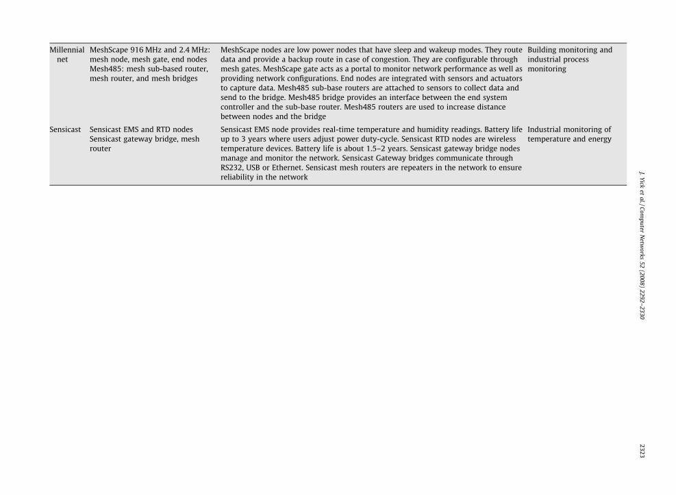
Millennialnet
MeshScape 916 MHz and 2.4 MHz:mesh node, mesh gate, end nodes
MeshScape nodes are low power nodes that have sleep and wakeup modes. They routedata and provide a backup route in case of congestion. They are configurable throughmesh gates. MeshScape gate acts as a portal to monitor network performance as well asproviding network configurations. End nodes are integrated with sensors and actuatorsto capture data. Mesh485 sub-base routers are attached to sensors to collect data andsend to the bridge. Mesh485 bridge provides an interface between the end systemcontroller and the sub-base router. Mesh485 routers are used to increase distancebetween nodes and the bridge
Building monitoring andindustrial processmonitoringMesh485: mesh sub-based router,
mesh router, and mesh bridges
Sensicast Sensicast EMS and RTD nodesSensicast gateway bridge, meshrouter
Sensicast EMS node provides real-time temperature and humidity readings. Battery lifeup to 3 years where users adjust power duty-cycle. Sensicast RTD nodes are wirelesstemperature devices. Battery life is about 1.5–2 years. Sensicast gateway bridge nodesmanage and monitor the network. Sensicast Gateway bridges communicate throughRS232, USB or Ethernet. Sensicast mesh routers are repeaters in the network to ensurereliability in the network
Industrial monitoring oftemperature and energy
J.Yicket
al./Computer
Netw
orks52
(2008)2292–
23302323

Appendix B
The following table shows a comparison between the different types of wireless sensor networks:
Terrestrial WSN Underground WSN Underwater WSN Multi-media W Mobile WSN
Definition A network consists ofhundreds to thousands ofsensor nodes deployed onland
A network consists ofwireless sensor nodesdeployed in caves ormines or underground
A network consists ofwireless sensor andvehicles deployed intothe ocean environment
A network cons of wireless sensordevices that hav e ability to store,process, and ret e multi-media datasuch as video, a , and images
A network consistsof mobile sensornodes that have theability to move
Challenges – In-network data aggre-gation to improve perfor-mance across communi-cation, energy cost, anddelay
– Minimizing energy cost– Reduce the amount of
data communication– Finding the optimal route– Distributing energy
consumption– Maintaining network
connectivity– Eliminating redundancy
– Expensive deploymentmaintenance, andequipment cost
– Threats to device suchas the environmentand animals
– Battery power cannoteasily be replaced
– Topology challengeswith pre-planneddeployment
– High levels of attenua-tion and signal loss incommunication
– Expensive underwatersensors
– Hardware failure dueto environment effects(e.g., corrosion)
– Battery power cannoteasily be replaced
– Sparse deployment– Limited bandwidth– Long propagation
delay, high latency,and fading problems
– In-network cessing, filtering, andcompressing ulti-media content
– High energy nsumption and band-width deman
– Deployment sed on multi-mediaequipment co age
– Flexible archi ure to support differentapplications
– Must integra arious wirelesstechnologies
– QoS provision is very difficult due tolink capacity delays
– Effective cros yer design
– Navigating andcontrolling mobilenodes
– Mustself-organized
– Localization withmobility
– Minimize energycost
– Maintaining net-work connectivity
– In-network dataprocessing
– Data distribution– Mobility
management– Minimize energy
usage inlocomotion
– Maintainadequate sensingcoverage
Applications – Environmental sensingand monitoring
– Industrial monitoring– Surface explorations
– Agriculture monitoring– Landscape
management– Underground struc-
tural monitoring– Underground environ-
ment monitoring ofsoil, water or mineral
– Military bordermonitoring
– Pollution monitoring– Undersea surveillance
and exploration– Disaster prevention
monitoring– Seismic monitoring– Equipment monitoring– Underwater robotics
– Enhancement existing WSN applica-tions such as king and monitoring
– Environmentalmonitoring
– Habitatmonitoring
– Militarysurveillance
– Target tracking– Underwater
monitoring– Search and rescue
2324J.Yick
etal./Com
puterN
etworks
52(2008)
2292–2330
SN
istse thrievudioproof m
cod
bavertect
te v
ingands-la
totrac

Appendix C
The following table shows a comparison between the applications and the communication protocols
Application Application characteristic Transportlayer
Network layer Data-lin er Physical layer
PinPtr [2] – can tolerate multiple sensor failures– provides good coverage and high accuracy– services use include synchronization, data
aggregation, and localization– can tolerate small latency
– multi-hop routing – – mica mote with a multi-channeltransceiver is used
– acoustic signal detection of events
Macroscope inthe redwood[22]
– robust system– supports data aggregation– synchronization– position of the sensor can largely affect the
result of the data– lacks the ability to detect failures in the network
– – multi-hop robustrouting (MinRoute)
– – duty-cycling for powerconservation
Semiconductorplants andoil tanker[23]
– Self configuration– Security– Maintainability and log network lifetime– Must achieve adequate coverage– Eliminate interference– Must be energy efficient to meet battery lifetime– Centralized protocol used for power
management– Must be fault tolerant– Higher data rate using Intel motes compare to
Mica2 motes
– – Single-destination-DSDV routing
– End-t dreliab lktransf otocol
– Assessing RF coverage and identi-fying interferences
– Duty-cycling for powerconservation
Underwatermonitoring[24]
– Localization of an autonomous vehicle under wateris very difficult
– Reliability of hardware, software, and data trans-fer is very important
– – Direct connection,single hop
– CRC c sum forerror ction
– Packe packetdelive r groupsof pa deliverydepen on thecomm ationlink
– Ultrasonic and optical communica-tion are used.
– Advantage of acoustic communica-tion is long-range communication,can be used for localization
– Disadvantage of acoustic commu-nication is the limited bandwidth,long propagation delay, and signalfading issue
– Advantage of optimal communica-tion has high data rate due to highfrequency signal but cost less thanultrasonic
– Disadvantage of optical communi-cation is short-range communica-tion and line-of-sight operations
– Pulse position modulation(continued on next page)
J.Yicket
al./Computer
Netw
orks52
(2008)2292–
23302325
k lay
o-enle buer pr
heckdetet-by-ry o
cketdingunic

Appendix C (continued)
Application Application characteristic Transportlayer
Network layer Data-link layer Physical layer
MAX [25] – Human-centric operation– System has to be robust to reconfiguration– Must be secured from unauthorized access– Minimum delay– Efficiency in energy, band-width, and memory– Hierarchical architecture– Tradeoff between computation, processing and
storage
– – Two-hop connec-tion from the tagsto the sub-stationand from the sub-station to the basestation
– Polling protocol isused between thebase station andsub-stations tominimize delayand collision
– Radio frequency with receivedsignal strength indicator (RSSI) isused. (Chipcon’s CC1000 radiotransceiver)
CenWits [26] – Provides adaptive tradeoff between memory andpower consumption
– Issue: limited memory available sensor motes– Size of stored information can be very large– Information must be organized and processed
efficiently– Power management with group set
communication
– – Direct connectionto another sensoror access point
– – MICA2 sensor nodes equippedwith a GPS receiver and RFtransmitter
– GPS has its limitation when used inthe canyons and rainy forest Cen-wits addresses this by incorporat-ing location point
– Transmission beaconing adaptsthe users speed for powermanagement
Cyclops [27] – High speed data transfer and processing– High resolution images– Power consumption is minimal– Delay sensitive– Several power states to minimize energy
– Direct connection
Petroleumfacility [28]
– Reliable data rate– Minimum latency– Accurate end-to-end signal– Minimize energy
– – Multi-hop routing – –
Volcanomonitoring[32]
– Sparse deployment– Linear configuration– High data rates– High battery consumption– Must have reliable data transmission– Time must be synchronized– Java-based GUI for network monitoring
– – Multi-hop routing(MultiHopLQI)
– –
Health caremonitoring[33]
– infant monitoring– alert the deaf– blood pressure monitoring and tracking– vital sign monitoring
– – Direct connection – – T-mote and SHIMMER motesequipped with pressure and tem-perature sensors, and microphone
ZebraNet [9] – Mobile sensor nodes must accurately logpositions
– Communication latency is not important– Sparse system– Flash memory to store data– High power consumption– Conserve power by duty-cycling node and GPS– Use rechargeable battery with a solar array
– – Flooding – – Duty-cycle to conserve energy
2326J.Yick
etal./Com
puterN
etworks
52(2008)
2292–2330

J. Yick et al. / Computer Networks 52 (2008) 2292–2330 2327
References
[1] I.F. Akyildiz, W. Su, Y. Sankarasubramaniam, E. Cayirci, A survey onsensor networks, IEEE Communications Magazine 40 (8) (2002)104–112.
[2] G. Simon, M. Maroti, A. Ledeczi, G. Balogh, B. Kusy, A. Nadas, G. Pap, J.Sallai, K. Frampton, Sensor network-based countersniper system, in:Proceedings of the Second International Conference on EmbeddedNetworked Sensor Systems (Sensys), Baltimore, MD, 2004.
[3] J. Yick, B. Mukherjee, D. Ghosal, Analysis of a Prediction-basedMobility Adaptive Tracking Algorithm, in: Proceedings of the IEEESecond International Conference on Broadband Networks(BROADNETS), Boston, 2005.
[4] M. Castillo-Effen, D.H. Quintela, R. Jordan, W. Westhoff, W. Moreno,Wireless sensor networks for flash-flood alerting, in: Proceedings ofthe Fifth IEEE International Caracas Conference on Devices, Circuits,and Systems, Dominican Republic, 2004.
[5] T. Gao, D. Greenspan, M. Welsh, R.R. Juang, A. Alm, Vital signsmonitoring and patient tracking over a wireless network, in:Proceedings of the 27th IEEE EMBS Annual InternationalConference, 2005.
[6] K. Lorincz, D. Malan, T.R.F. Fulford-Jones, A. Nawoj, A. Clavel, V.Shnayder, G. Mainland, M. Welsh, S. Moulton, Sensor networks foremergency response: challenges and opportunities, PervasiveComputing for First Response (Special Issue), IEEE PervasiveComputing, October–December 2004.
[7] G. Wener-Allen, K. Lorincz, M. Ruiz, O. Marcillo, J. Johnson, J. Lees,M. Walsh, Deploying a wireless sensor network on an activevolcano, Data-Driven Applications in Sensor Networks (SpecialIssue), IEEE Internet Computing, March/April 2006.
[8] V. Raghunathan, A. Kansai, J. Hse, J. Friedman, M. Srivastava, Designconsiderations for solar energy harvesting wireless embeddedsystems, in: Proceedings of the IPSN, 2005, 457–462.
[9] P. Zhang, C.M. Sadler, S.A. Lyon, M. Martonosi, Hardware designexperiences in ZebraNet, in: Proceedings of the SenSys’04,Baltimore, MD, 2004.
[10] S. Roundy, J.M. Rabaey, P.K. Wright, Energy Scavenging for WirelessSensor Networks, Springer-Verlag, New York, LLC, 2004.
[11] M. Rahimi, H. Shah, G.S. Sukhatme, J. Heideman, D. Estrin, Studyingthe feasibility of energy harvesting in mobile sensor network, in:Proceedings of the IEEE ICRA, 2003, pp. 19–24.
[12] A. Kansai, M.B. Srivastava, An environmental energy harvestingframework for sensor networks, in: Proceedings of the InternationalSymposium on Low Power Electronics and Design, 2003, pp. 481–486.
[13] S. Toumpis, T. Tassiulas, Optimal deployment of large wirelesssensor networks, IEEE Transactions on Information Theory 52(2006) 2935–2953.
[14] J. Yick, G. Pasternack, B. Mukherjee, D. Ghosal, Placement ofnetwork services in sensor networks, Self-Organization Routingand Information, Integration in Wireless Sensor Networks (SpecialIssue) in International Journal of Wireless and Mobile Computing(IJWMC) 1 (2006) 101–112.
[15] D. Pompili, T. Melodia, I.F. Akyildiz, Deployment analysis inunderwater acoustic wireless sensor networks, in: WUWNet, LosAngeles, CA, 2006.
[16] I.F. Akyildiz, E.P. Stuntebeck, Wireless underground sensor networks:research challenges, Ad-Hoc Networks 4 (2006) 669–686.
[17] M. Li, Y. Liu, Underground structure monitoring with wirelesssensor networks, in: Proceedings of the IPSN, Cambridge, MA, 2007.
[18] I.F. Akyildiz, D. Pompili, T. Melodia, Challenges for efficientcommunication in underwater acoustic sensor networks, ACMSigbed Review 1 (2) (2004) 3–8.
[19] J. Heidemann, Y. Li, A. Syed, J. Wills, W. Ye, Underwater sensornetworking: research challenges and potential applications, in:Proceedings of the Technical Report ISI-TR-2005-603, USC/Information Sciences Institute, 2005.
[20] I.F. Akyildiz, T. Melodia, K.R. Chowdhury, A survey on wirelessmultimedia sensor networks, Computer Networks Elsevier 51(2007) 921–960.
[21] D. Gay, P. Levis, R.v. Behren, The nesC language: a holistic approachto networked embedded systems, in: Proceedings of the PLDI, SanDiego, CA, 2003.
[22] G. Tolle, J. Polastre, R. Szewczyk, D. Culler, N. Turner, K. Tu, S.Burgess, T. Dawson, P. Buonadonna, D. Gay, W. Hong, A macroscopein the redwoods, in: Proceedings of the Third InternationalConference on Embedded Networked Sensor Systems (Sensys),San Diego, CA, 2005.
[23] L. Krishnamurthy, R. Adler, P. Buonadonna, J. Chhabra, M. Flanigan,N. Kushalmager, L. Nachman, M. Yarvis, Design and deployment of
industrial sensor networks: experiences from a semiconductorplant and the North Sea, in: Proceedings of the Third InternationalConference on Embedded Networked Sensor Systems (Sensys), SanDiego, CA, 2005.
[24] I. Vasilescu, K. Kotay, D. Rus, M. Dunbabin, P. Corke, Data collection,storage, retrieval with an underwater sensor network, in:Proceedings of the Third International Conference on EmbeddedNetworked Sensor Systems (Sensys), San Diego, CA, 2005.
[25] K.K. Yap, V. Srinivasan, M. Motani, MAX: Human-centric search ofthe physical world, in: Proceedings of the Third InternationalConference on Embedded Networked Sensor Systems (Sensys), SanDiego, CA, 2005.
[26] J.H. Huang, S. Amjad, S. Mishra, CenWits: A sensor-based looselycoupled search and rescue system using witnesses, in: Proceedingsof the Third International Conference on Embedded NetworkedSensor Systems (Sensys), San Diego, CA, 2005.
[27] M. Rahimi, R. Baer, O.I. Iroezi, J.C. Garcia, J. Warrior, D. Estrin, M.Srivastava, Cyclops: in situ image sensing and interpretation inwireless sensor networks, in: Proceedings of the Third InternationalConference on Embedded Networked Sensor Systems (Sensys), SanDiego, CA, 2005.
[28] I. Johnstone, J. Nicholson, B. Shehazad, J. Slipp, Experiences from awireless sensor network deployment in a petroleum environment,in: IWCMC, Honolulu, Hawaii, 2007.
[29] Moteiv, <http://moteiv.com>.[30] SOHOware Inc., <http://www.sohoware.com>.[31] Technologic Systems, <http://www.embeddedarm.com>.[32] G. Werner-Allen, K. Lorincz, M. Welsh, O. Marcillo, J. Johnson, M.
Ruiz, J. Lees, Deploying a wireless sensor network on an activevolcano, IEEE Internet Computing 10 (2006) 18–25.
[33] C.R. Baker, K. Armijo, S. Belka, M. Benhabib, V. Bhargava, N. Burkhart,A.D. Minassians, G. Dervisoglu, L. Gutnik, M.B. Haick, C. Ho, M.Koplow, J. Mangold, S. Robinson, M. Rosa, M. Schwartz, C. Sims, H.Stoffregen, A. Waterbury, E.S. Leland, T. Pering, P.K. Wright, Wirelesssensor networks for home health care, in: AINAW, Ontario, Canada,2007.
[34] M. Leopold, M.B. Dydensborg, P. Bonnet, Bluetooth and sensornetworks: a reality check, in: Proceedings of the Sensys’03, LosAngeles, CA, 2003.
[35] L. Gu, D. Jia, P. Vicaire, T. Yan, L. Luo, A. Tirumala, Q. Cao, T. he, J.A.Stankovic, T. Abdelzaher, B.H. Krogh, Lightweight detection andclassification for wireless sensor networks in realistic environment,in: Proceedings of the Sensys’05, Los Angeles, CA, 2005.
[36] S.Y. Cheung, S.C. Ergen, P. Varaiya, Traffic surveillance with wirelessmagnetic sensors, in: Proceedings of the 12th ITS World Congress,San Francisco, CA, 2005.
[37] I. Howitt, J.A. Gutierrez, IEEE802.15.4 low rate-wireless personalarea network coexistence issues, Wireless Communications andNetworking 3 (2003) 1481–1486.
[38] ZigBee: wireless control that simply works, <http://www.zigbee.org>.
[39] ZigBee Standards Overview, <http://www.freescale.com/webapp/sps/site/overview.jsp?nodeId=01J4Fs25657725>.
[40] HART – The Logical Wireless Solution, <http://www.hartcomm2.org/hart_protocol/wireless_hart/hart_the_logical_solution.html>.
[41] Draft standard: What’s in the April’07 WirelessHART specification,<http://www.controleng.com/article/CA6427951.html>.
[42] ISA100.11a, <http://www.isa.org/MSTemplate.cfm?MicrositeID=1134&CommitteeID=6891>.
[43] 6LoWPAN, <http://6lowpan.net/>.[44] G. Mulligan, L.W. Group, The 6LoWPAN architecture, in:
Proceedings of the EmNets, Cork, Ireland, 2007.[45] G. Montenegro, N. Kushalnagar, J. Hui, D. Culler, Transmission of
IPv6 packets over IEEE 802.15.4 networks, RFC 4944 (2007).[46] IEEE Standard 802.15.3, Wireless medium access control (MAC) and
physical layer (PHY) specifications for high rate wireless personarea networks (WPANs), September 2003.
[47] Wibree, <http://www.wibree.com/>.[48] J. Newsome, D. Song, GEM: Graph EMbedding for routing and data-
centric storage in sensor networks without geographic information,in: Proceedings of the Sensys’03, San Diego, CA, 2003.
[49] P. Desnoyers, D. Ganesan, P. Shenoy, TSAR: a two tier sensor storagearchitecture using interval skip graphs, in: Proceedings of the ThirdInternational Conference on Embedded Networked Sensor Systems(Sensys), San Diego, CA, 2005.
[50] D. Ganesan, B. Greenstein, D. Perelyubskiy, D. Estrin, J. Heidemann,An evaluation of multi-resolution storage for sensor networks, in:Proceedings of the Sensys’03, Los Angeles, CA, 2003.

2328 J. Yick et al. / Computer Networks 52 (2008) 2292–2330
[51] D. Raychaudhuri, I. Seskar, M. Ott, S. Ganu, K. Ramachandran, H.Kremo, R. Siracusa, H. Liu, M. Singh, Overview of the ORBIT radiogrid testbed for evaluation of next-generation wireless networkprotocols, in: Proceedings of the IEEE Wireless Communicationsand Networking Conference, 2005.
[52] G. Werner-Allen, P. Swieskowski, M. Welsh, MoteLab: a wirelesssensor network testbed, in: ISPN, 2005.
[53] Crossbow Technology, <http://www.xbow.com>.[54] D. Johnson, T. Stack, R. Fish, D.M. Flickinger, L. Stoller, R. Ricci, J.
Lepreau, Mobile Emulab: a robotic wireless and sensor networktestbed, in: IEEE INFOCOM, 2006.
[55] J. Zhao, R. Govindan, Understanding packet delivery performance indense wireless sensor networks, in: Proceedings of the FirstInternational Conference on Embedded Networked SensorSystems (Sensys), Los Angeles, CA, 2003.
[56] D. Moore, J. Leonard, D. Rus, S. Teller, Robust distributed networklocalization with noisy range measurements, in: Proceedings of theSensys’04, San Diego, CA, 2004.
[57] M. Maroti, B. Kusy, G. Balogh, P. Volgyesi, A. Nadas, K. Molnar, S.Dora, A. Ledeczi, Radio interferometric geolocation, in: Proceedingsof the Third International Conference on Embedded NetworkedSensor Systems (Sensys), San Diego, CA, 2005.
[58] R. Stoleru, T. He, J.A. Stankovic, D. Luebke, A high-accuracy, low-costlocalization system for wireless sensor networks, in: Proceedings ofthe Third International Conference on Embedded NetworkedSensor Systems (Sensys), San Diego, CA, 2005.
[59] A. Srinivasan, J. Wu, A survey on secure localization in wirelesssensor networks, in: B. Furht (Ed.), Wireless and MobileCommunications, CRC Press/Taylor and Francis Group, BocaRaton/London, 2007.
[60] L. Lazos, R. Poovendran, SeRLoc: secure range independentlocalization for wireless sensor networks, in: First IEEEInternational Conference on Mobile Ad hoc and Sensor Systems,Fort Lauderdale, FL, 2004.
[61] D. Liu, P. Ning, W. Du, Detecting malicious beacon nodes for securelocation discovery in wireless sensor networks, in: Proceedings ofthe 25th IEEE International Conference on Distributed ComputingSystems (ICDC’05), 2005.
[62] A. Srinivasan, J. Teitelbaum, J. Wu, DRBTS: Distributed reputation-based beacon trust system, in: Proceedings of the 2nd IEEEInternational Symposium on Dependable, Autonomic and SecureComputing (DASC’06), 2006, pp. 277–283.
[63] S. Capkun, J.-P. Hubaux, Secure positioning of wireless devices withapplication to sensor networks, in: Proceedings of the IEEEINFOCOM’05, 2005.
[64] L. Lazos, R. Poovendran, S. Capkun, ROPE: robust position estimationin wireless sensor networks, in: Proceedings of the IPSN’05, 2005.
[65] N.B. Priyantha, H. Balakrishnan, E.D. Demaine, S. Teller, Mobile-assisted localization in wireless sensor networks, in: Proceedings ofthe IEEE INFOCOM, Miami, FL, 2005.
[66] S. Ganeriwal, D. Ganesan, H. Shim, V. Tsiatsis, B. Srivastava,Estimating clock uncertainty for efficient duty-cycling in sensornetworks, in: Proceedings of the Third International Conference onEmbedded Networked Sensor Systems (Sensys), San Diego, CA, 2005.
[67] D. Lucarelli, I.-J. Wang, Decentralized synchronization protocolswith nearest neighbor communication, in: Proceedings of theSensys’04, Baltimore, MD, 2004.
[68] G. Wener-Allen, G. Tewari, A. Patel, M. Welsh, R. Nagpal, Firefly-inspired sensor network synchronicity with realistic radio effects,in: Proceedings of the Third International Conference on EmbeddedNetworked Sensor Systems (Sensys), San Diego, CA, 2005.
[69] M. Maroti, B. Kusy, G. Simon, A. Ledeczi, Synchronization of pulse-coupled biological oscillators, SIAM 50 (1990) 1645–1662.
[70] S. Ganeriwal, R. Kumar, M.B. Srivastava, Timing-sync protocol forsensor networks, in: Proceedings of the Sensys’03, Los Angeles, CA,2003.
[71] J. Elson, L. Girod, D. Estrin, Fine-grained network timesynchronization using reference broadcasts, in: Proceedings of the5th symposium on Operation System Design and Implementation(OSDI 2002), 2002.
[72] C.H. Rentel, T. Kunz, A clock-sampling mutual network synchroniza-tion algorithm for wireless ad hoc networks, in: Proceedings of theIEEE Wireless Communications and Networking Conference, 2005.
[73] H. Dai, R. Han, TSync: a lightweight bidirectional timesynchronization service for wireless sensor networks, ACMSIGMOBILE, Mobile Computing and Communications Review 8(January) (2004) 125–139.
[74] Q. Li, D. Rus, Global clock synchronization in sensor networks, in:Proceedings of the INFOCOM, 2004, pp. 564–574.
[75] B. Sundararaman, U. Buy, A.D. Kshemkalyani, Clock synchronizationfor wireless sensor network: a survey, Ad-Hoc Networks 3 (May)(2005) 281–323.
[76] X. Wang, G. Xing, Y. Zhang, C. Lu, R. Pless, C. Gill, Integratedcoverage and connectivity configuration in wireless sensornetworks, in: Proceedings of the First International Conference onEmbedded Networked Sensor Systems (Sensys), Los Angeles, CA,2003.
[77] B. Chen, K. Jamieson, H. Balakrishnan, R. Morris, Span: an energy-efficient coordination algorithm for topology maintenance in adhoc wireless networks, in: Proceedings of the ACM/IEEEInternational Conference on Mobile Computing and Networking(MobiCom), Rome, Italy, 2001.
[78] G. Veltri, Q. Huang, G. Qu, M. Potkonjak, Minimal and maximalexposure path algorithms for wireless embedded sensornetworks, in: Proceedings of the First International Conference onEmbedded Networked Sensor Systems (Sensys), Los Angeles, CA,2003.
[79] T. Yan, T. He, J.A. Stankovic, Differentiated surveillance for sensornetworks, in: Proceedings of the First International Conference onEmbedded Networked Sensor Systems (Sensys), Los Angeles, CA,2003.
[80] S. Nath, P.B. Gibbons, S. Seshan, Z.R. Anderson, Synopsis diffusionfor robust aggregation in sensor networks, in: Proceedings of theSensys’04, Baltimore, MD, 2004.
[81] N. Shrivastava, C. Buragohain, D. Agrawal, S. Suri, Medians andbeyond: new aggregation techniques for sensor networks, in:Proceedings of the Sensys’04, Baltimore, MD, 2004.
[82] A. Wacker, M. Knoll, T. Heiber, K. Rothermel, A new approach forestablishing pairwise keys for securing wireless sensor networks,in: Proceedings of the Third International Conference on EmbeddedNetworked Sensor Systems (Sensys), San Diego, CA, 2005.
[83] F. Liu, M.J.M. Rivera, X. Cheng, Location-aware key establishment inwireless sensor networks, in: Proceedings of the InternationalWireless Communications and Mobile Computing Conference(IWCMC), Vancouver, Canada, 2006.
[84] M.O. Rabin, Digitalized signatures and public-key functions asinteractable as factorization, Technical Report MIT/LCS/TR-212,Laboratory for Computer Science, MIT, 1979.
[85] C. Karlof, N. Sastry, D. Wagner, TinySec: a link layer securityarchitecture for wireless sensor networks, in: Proceedings of theSensys’04, Baltimore, MD, 2004.
[86] Y.G. Iyer, S. Gandham, S. Venkatesan, STCP: a generic transportlayer protocol for wireless sensor networks, in: Proceedings of the14th IEEE International Conference on Computer Communicationsand Networks, San Diego, CA, 2005.
[87] Y. Zhou, M.R. Lyu, PORT: a price-oriented reliable transport protocolfor wireless sensor network, in: Proceedings of the 16th IEEEInternational Symposium on Software Reliability Engineering(ISSRE), Chicago, IL, 2005.
[88] S.-J. Park, R. Vedantham, R. Sivakumar, I.F. Akyildiz, A scalableapproach for reliable downstream data delivery in wireless sensornetworks, in: Proceedings of the ACM MobiHoc’04, Roppongi,Japan, 2004.
[89] V.C. Gungor, O.B. Akan, DST: Delay sensitive transport in wirelesssensor networks, in: Proceedings of the Seventh IEEE InternationalSymposium on Computer Networks (ISCN), 2006, pp. 116–122.
[90] C.-Y. Wan, A.T. Campbell, L. Krishnamurthy, PSFQ: a reliabletransport protocol for wireless sensor, in: Proceedings of the 1stACM International workshop on Wireless Sensor Networks andApplications, 2002, pp. 1–11.
[91] Y. Sankarasubramaniam, O.B. Akan, I.F. Akyilidiz, ESRT: event-to-sink reliable transport in wireless sensor networks, in: Proceedingsof the MobiHoc, Annapolis, MD, 2003.
[92] C.-Y. Wan, S.B. Eisenman, A.T. Campbell, CODA: Congestiondetection and avoidance in sensor networks, in: Proceedings ofthe Sensys, 2003.
[93] K. Seada, M. Zuniga, A. Helmy, B. Krishnamachari, Energy-efficientforwarding strategies for geographic routing in lossy wirelesssensor networks, in: Proceedings of the Sensys’04, Baltimore, MD,2004.
[94] R. Zhang, H. Zhao, M.A. Labrador, The anchor location service (ALS)protocol for large-scale wireless sensor networks, in: Proceedingsof the First International on Integrated Internet Ad hoc and SensorNetworks, Nice, France, 2006.
[95] J. Yin, S. Madria, SecRout: a secure routing protocol for sensornetworks, in: Proceedings of the 20th International Conference onAdvanced Information Networking and Applications (AINA’06),Vienna, Austria, 2006.

J. Yick et al. / Computer Networks 52 (2008) 2292–2330 2329
[96] X. Du, Y. Xiao, H.-H. Chen, Q. Wu, Secure cell relay routing protocolfor sensor networks, Wireless Communications and MobileComputing 6 (2006) 375–391.
[97] R.K. Ganti, P. Jayachandran, H. Luo, T.F. Abdelzaher, Datalinkstreaming in wireless sensor networks, in: Proceedings of theSensys’06, Boulder, CO, 2006.
[98] R.E. Blahut, Theory and Practice of Error Control Coding, Addison-Wesley, New York, 1983.
[99] H. Liu, H. Ma, M.E. Zarki, S. Gupta, Error control schemes fornetworks: an overview, ACM Mobile Networking and Applications(MONET) 2 (1997) 167–182.
[100] H. Dubois-Ferriere, D. Estrin, M. Vetterli, Packet combining in sensornetworks, in: Proceedings of the Sensys’05, San Diego, CA, 2005.
[101] A. Miu, H. Balakrishnan, C.E. Koksal, Improving loss resilience withmulti-radio diversity in wireless networks, in: Proceedings of theACM MobiCom, Cologne, Germany, 2005.
[102] V. Rajendran, K. Obraczka, J.J. Garcia-Luna-Aceves, Energy-efficient, collision-free medium access control for wirelesssensor networks, in: Proceedings of the First InternationalConference on Embedded Networked Sensor Systems (Sensys),Los Angeles, CA, 2003.
[103] J. Polastre, J. Hill, D. Culler, Versatile low power media access forwireless sensor networks, in: Proceedings of the Sensys’04, SanDiego, CA, 2004.
[104] S. Mishra, A. Nasipuri, An adaptive low power reservation basedMAC protocol for wireless sensor networks, in: Proceedings of theIEEE International Conference on Performance Computing andCommunications, 2004, pp. 316–329.
[105] C. Guo, L.C. Zhong, J.M. Rabaey, Low power distributed MAC for adhoc sensor radio networks, in: Proceedings of the IEEE Globecom,2001, pp. 2944–2948.
[106] M.C. Vuran, I.F. Akyildiz, Spatial correlation-based collaborativemedium access control in wireless sensor networks, IEEE/ACMTransactions on Networking 14 (2006) 316–329.
[107] K.D. Wong, Physical layer consideration for wireless sensornetworks, in: Proceedings of the IEEE International Conference onNetworking, Sensing and Control, Taipei, Taiwan, 2004.
[108] A.Y. Wang, S. Cho, C.G. Sodini, A.P. Chandrakasan, Energy efficientmodulation and MAC for asymmetric RF microsensor systems, in:Proceedings of the ISLPED’01, Huntington Beach, CA, 2001.
[109] C.C. Enz, A. El-Hoiydi, J.-D. Decotignia, V. Peiris, WiseNET: anultralow-power wireless sensor network solution, IEEE ComputerSociety 37 (2004) 62–70.
[110] E. Shih, S.-H. Cho, N. Ickes, R. Min, A. Sinha, A. Wang, A.Chandrakasan, Physical layer driven protocol and algorithmdesign for energy efficient wireless sensor networks, in: ACMSIGMOBILE, Rome, Italy, 2001.
[111] S. Cui, A.J. Goldsmith, A. Bahai, Energy-constrained modulationoptimization, IEEE Transactions on Wireless Communication 4(2005) 2349–2360.
[112] J. Ammer, J. Rabaey, The energy-per-useful-bit metric forevaluating and optimizing sensor network physical layers, in:Proceedings of the IWWAN’06, 2006.
[113] J. Polastre, J. Hui, P. Levi, J. Zhao, D. Culler, S. Shenker, I. Stoica, Aunifying link abstraction for wireless sensor networks, in:Proceedings of the third International Conference on EmbeddedNetworked Sensor Systems (Sensys), San Diego, CA, 2005.
[114] L.V. Hoesel, T. Nieberg, J. Wu, P.J.M. Havinga, Prolonging thelifetime of wireless sensor networks by cross-layer interaction,IEEE Wireless Communications Magazine 11 (December) (2004)78–86.
[115] W. Ye, J. Heidemann, D. Estrin, An energy-efficient MAC protocolfor wireless sensor network, in: Proceedings of the Infocom, NewYork, 2002.
[116] D.B. Johnson, D.A. Maltz, Dyanmic source routing, in: T. Imielinski,H.F. Korth (Eds.), Ad Hoc Wireless Networks Mobile Computing,vol. 353, 1996.
[117] S. Cui, R. Madan, A.J. Goldsmith, S. Lall, Joint routing MAC and linklayer optimization in sensor networks with energy constraints, in:Proceedings of the IEEE ICC, 2005, pp. 725–729.
[118] I.F. Akyildiz, M.C. Vuran, O.B. Akan, A cross-layer protocol forwireless sensor networks, in: Proceedings of the Conference onInformation Science and Systems (CISS), 2006.
[119] P. Skraba, H. Aghajan, A. Bahai, Cross-layer optimization for highdensity sensor networks: distributed passive routing decisions, in:Proceedings of the Ad-Hoc Now’04, Vancouver, 2004.
[120] M. Zorzi, R. Rao, Geographic random forwarding (GeRaF) for ad hocand sensor networks: multihop performance, IEEE Transactions onMobile Computing 2 (2003) 337–348.
[121] M. Chiang, Balancing transport and physical layers in wirelessmultihop networks: jointly optimal congestion control and powercontrol, IEEE Journal on Selected Area in Communications (JSAC) 23(2005) 104–116.
[122] M. Chiang, To layer or not to layer: balancing transport andphysical layers in wireless multihop networks, in: Proceedings ofthe IEEE INFOCOM, 2004, pp. 2525–2536.
[123] R. Madan, S. Cui, S. Lall, A. Goldsmith, Cross-layer design forlifetime maximization interference-limited wireless sensornetworks, IEEE Communications on Wireless Communications 5(2005) 3142–3152.
Jennifer Yick received the BS Degree inComputer Science and Engineering from theUniversity of California, Davis, in 2001, andthe MS Degree in Computer Science from theUniversity of California, Davis, in 2004. She iscurrently a PhD candidate in the Departmentof Computer Science at University of Califor-nia, Davis. Her current research interestsinclude energy conservation, localization,clustering, target tracking and network sur-vivability in wireless sensor networks.
Biswanath Mukherjee (S082–M087) receivedthe BTech (Hons) Degree from Indian Instituteof Technology, Kharagpur, India in 1980 andthe PhD Degree from University of Washing-ton, Seattle in June 1987. At Washington, heheld a GTE Teaching Fellowship and a GeneralElectric Foundation Fellowship. In July 1987,he joined the University of California, Davis,where he has been Professor of ComputerScience since July 1995 (and currently holdsthe Child Family Endowed Chair Professor-ship), and served as Chairman of the Depart-
ment of Computer Science during from September 1997 to June 2000. Heis winner of the 2004 Distinguished Graduate Mentoring Award at UCDavis. Two PhD Dissertations (by Dr. Laxman Sahasrabuddhe and Dr.
Keyao Zhu), which were supervised by Professor Mukherjee, were win-ners of the 2000 and 2004 UC Davis College of Engineering DistinguishedDissertation Awards. To date, he has graduated nearly 25 PhD students,with almost the same number of MS students. Currently, he supervisesthe research of nearly 20 scholars, mainly PhD students and includingvisiting research scientists in his laboratory. He is Co-winner of paperawards presented at the 1991 and the 1994 National Computer SecurityConferences. He serves or has served on the editorial boards of the IEEE/ACM Transactions on Networking, IEEE Network, ACM/Baltzer WirelessInformation Networks (WINET), Journal of High Speed Networks, Pho-tonic Network Communications, Optical Network Magazine, and OpticalSwitching and Networking. He served as Editor-at-Large for optical Net-working and Communications for the IEEE Communications Society; asthe Technical Program Chair of the IEEE INFOCOM’96 conference; and asChairman of the IEEE Communication Society’s Optical NetworkingTechnical Committee (ONTC) during 2003–2005. He is Author of thetextbook ‘Optical WDM Networks’ published by Springer in January 2006.Earlier, he Authored the textbook ‘Optical Communication Networks’published by McGraw-Hill in 1997, a book which received the Associationof American Publishers, Inc.’s 1997 Honorable Mention in ComputerScience. He is a Member of the Board of Directors of IPLocks, Inc., a SiliconValley startup company. He has consulted for and served on the TechnicalAdvisory Board (TAB) of a number of startup companies in optical net-working. His current TAB appointments include: Teknovus, IntelligentFiber Optic Systems, and LookAhead Decisions, Inc. (LDI). His researchinterests include lightwave networks, network security, and wirelessnetworks.
etworks 52 (2008) 2292–2330
Dipak Ghosal received the BTech Degree inElectrical Engineering from Indian Institute
of Technology, Kanpur (India), in 1983, andMS Degree in Computer Science and Auto-mation from Indian Institute of Science,Bangalore, India, in 1985. He received hisPhD Degree in Computer Science from Uni-versity of Louisiana, in 1988. He is currentlya Professor in the Department of ComputerScience at the University of California, Davis.His primary research interests are in theareas of high speed and wireless networkswith particular emphasis on the impact of new technologies on thenetwork and higher layer protocols and applications. He is also inter-
2330 J. Yick et al. / Computer N
ested in the application of parallel architectures for protocol processingin high speed networks and in the application of distributed computingprinciples in the design of next generation network architectures andserver technologies.