Embed Size (px)
Citation preview
John Hawkyard MICorr
Deputy General ManagerRawabi Corrosion Technology Co Ltd
Al-Khobar
WIRELESS REMOTE MONITORING OF CATHODIC
PROTECTION SYSTEMS

Cathodic Protection is an electrochemical technique
which has been used for many years to prevent the
corrosion of buried and/or immersed metallic surfaces.
It utilizes the application of small amounts of electrical
current (d.c.) to the protected surface to counteract
the natural corrosion currents existing at the metal
surface.
The whole of the structure under protection is forced
to act as the cathode of an electrochemical cell, hence
the term CATHODIC PROTECTION (CP).
The types of structures which may be protected using
CP are wide ranging and include:
INTRODUCTION

Cross-country pipelines (Oil, Gas,
Water etc)
Storage Tanks
Fuel, Product, Water
Internal (Water), External
(Floor Plates)
Industrial Plant Piping
Systems
Concrete Structures
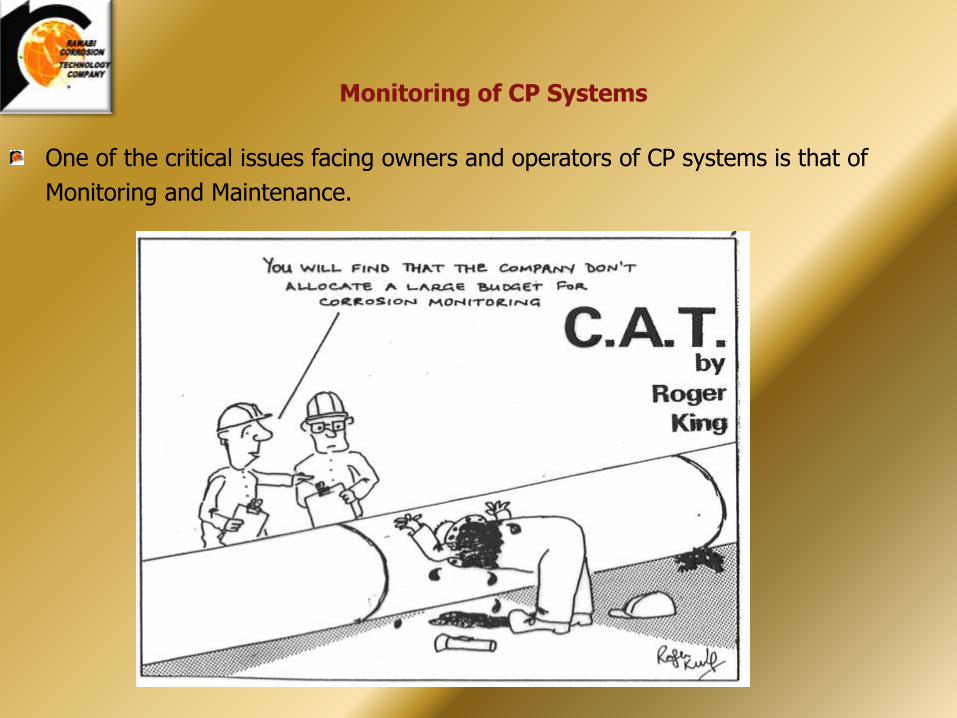
One of the critical issues facing owners and operators of CP systems is that of
Monitoring and Maintenance.
Monitoring of CP Systems

Installations may be in remote
or difficult to access areas
Monitoring can be time
consuming and a drain on
personnel resources
Working environments are often hazardous

Improperly executed Monitoring and Maintenance regimes are a
frequent cause of premature system failure.
Remember – incorrect operation of CP systems may result in lack
of protection and may even cause harm.
The Need for Remote Monitoring
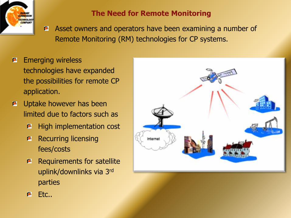
Asset owners and operators have been examining a number of
Remote Monitoring (RM) technologies for CP systems.
Emerging wireless
technologies have expanded
the possibilities for remote CP
application.
Uptake however has been
limited due to factors such as
High implementation cost
Recurring licensing
fees/costs
Requirements for satellite
uplink/downlinks via 3rd
parties
Etc..
The Need for Remote Monitoring
.
.
Recent world-wide, major corrosion events are now leading
companies to look for new, low cost alternatives for cathodic
protection remote monitoring
The benefits to asset owners are obvious:
Reduced ‘windshield time’
Reduced operator exposure to potentially hazardous
environments
‘Real time’ access to accurate system operational data
Automated reporting and alarming via inputs to existing
SCADA systems
Enables more effective use of personnel resources to achieve
timely and targeted maintenance tasks
The Need for Remote Monitoring

Recent technology development of low cost, fully integrated, cathodic
protection remote monitoring units (CP RMU) may provide the answer.
New, unlicensed, frequency hopping spread spectrum, wireless, application
specific CP RMU’s extend current technology with increased economical
viability enabling more companies to remotely monitor more assets.
Frequency Hopping Spread Spectrum (FHSS) Wireless Technology?
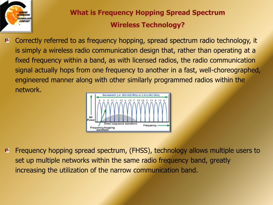
Correctly referred to as frequency hopping, spread spectrum radio technology, it
is simply a wireless radio communication design that, rather than operating at a
fixed frequency within a band, as with licensed radios, the radio communication
signal actually hops from one frequency to another in a fast, well-choreographed,
engineered manner along with other similarly programmed radios within the
network.
Frequency hopping spread spectrum, (FHSS), technology allows multiple users to
set up multiple networks within the same radio frequency band, greatly
increasing the utilization of the narrow communication band.
What is Frequency Hopping Spread Spectrum
Wireless Technology?

916MHz
Po
we
r
902 MHz 928 MHz
F1 F2F3 F4F5F6 F7F8 F9F10F11 F12F13 F14F15 F16
Frequency
FHSS: Hopping through the spectrum
What is Frequency Hopping Spread Spectrum Wireless Technology?

Provided all radios within each network hop at the same rate within the
same frequency band, network communications are effective.
Provided all networks within the band hop at different rates from each
other using frequency hopping techniques, then network
communications are effective.
Early FHSS systems did not include the same levels of proprietary
communication protocols, encryption, network ID’s, hopping patterns,
packet size selection, or hopping frequencies thus were prone to failure
due to data collisions, lost data or corrupted data.
What is Frequency Hopping Spread Spectrum Wireless Technology?
FHSS radios offered today have 6-level security features,
proprietary protocols and can hop up to 1,000 times per
second - making data collisions almost impossible.

Today, FHSS Manufacturers offer wireless CP RMU products with a wide variety of
selection, security, encryption and speed specifications as follows:
1. High Speed Communications: 115.2 Kbps true data throughput2. Long range: up to 60 kilometers line of sight, ability to extend range through
infinite repeaters.3. Error Free Communications: 32 bit CRC with automatic retransmission.4. Industrial Grade Specifications: Temperature cycle tested -40ºC to +75ºC.5. Repeater Capabilities: Each CP RMU can perform as a remote test site, a
repeater site and as a simultaneous test site/repeater. Repeaters can infinitely repeat.
6. Wide Supply Voltage Range: Supply voltage 10 to 30 VDC.7. Ultra Low Power Consumption: Current draw as low as 6 mA, 12 VDC in sleep
mode, and less than 86 mA in receiving mode. In sleep mode, CP RMU can awaken, synchronize and be ready to transmit data is less than 150 microseconds.
8. Separate Diagnostics Serial Ports: Allows real time simultaneous local diagnostics and setup without tying up main CP RMU communication port.
What is Frequency Hopping Spread Spectrum Wireless Technology?

No monthly recurring fees or costs
No initial or monthly licensing fees
Minimized network interferences
Maximum network security
Operates behind company firewall
Own your own data
Open protocol communications
Maximum system flexibility
Infinite repeatability
Maximum implementation into cabinetry
Minimized field wiring
FHSS technology offers the end user the flexibility of installing remote
monitoring equipment where it makes sense without concerns over
monthly fees, radio band licensing, network interferences or security.
FHSS Technology has come a long way since the 1930’s

Cathodic protection remote monitoring units, RMU’s, typically
monitor and report key corrosion protection activities including:
Pipe-to-soil potential
Rectifier output voltage
Rectifier output current
Rectifier input power status
CP RMU’s can offer remote operation of CP activities such as
rectifier interruption for maintenance purposes.
Modern CP RMU’s also monitor radio temperature and if
connected to a solar power generation system will also monitor
the battery voltage of the back up battery supply.
CP RMU Field Implementation

(-) (+)
Anode(s)Buried Steel Pipe (Cathode)
(-)
(+)
AC Input Power Supply
DC Output Power
Rectifier
R
VOUT
VRectifier(+)
Soil
Pipe
VRectifier(-)
AC Power
AC Power
Solar (+)
Solar (-)
DO Relay (-)
Battery (+)
DI1
Battery (-)
Sensor Power
Ground (-)
AI1 RSense
AI1 (-)
Protective Current
Permanent Ground Reference Electrode
Radio Communication Port
Solar Panel/Battery Charging Connector
I/O Termination Block
RS232/485 Communication Port
Diagnostics Communication Port
Cathodic Protection Monitoring Port
Radio Communication Antennae
Solar Charging Panel
Cathodic Protection Monitoring Radio
Backup Battery
3 inch Conduit Mounting Bracket
Rectifier Surface Mount Adapter Bracket
Ground Surface
Test Station Cathodic Protection Monitoring Radio
Wire Bond
Remote Rectifier Monitoring Station
Shunt Resistor
(+)(-)
A typical CP RMU Installation Schematic

In addition to monitoring the four process variables mentioned previously,
FHSS CP RMU’s may have additional channels to monitor, record and report:
Pipeline pressure
Pipeline temperature
Pump station sump level
Pump status on/off
Tank level
Ambient temperature
Other RMU Options

Central Operations Scada System and
Master Radio
Compressor Building
Compressor BuildingCompressor
Building
Gas Well
Gas Well
Gas Well
Gas Well
Gas Well
Gas Well
Gas Well
Gas Well
Gas Well
Gas Well
Gas Well
Gas Well
Gas Well
Gas Well
Gas Well
Gas Well
Gas Well
Gas Well
Gas WellGas
Well Gas WellGas
Well
Gas Well
Existing Pipeline Communication Network Devices
New Cathodic Protection Communication Network Devices
Rectifier
P2S Test
Rectifier
Rectifier
P2S Test
P2S Test
P2S Test
P2S Test
P2S Test
P2S Test
Rectifier
P2S Test
Rectifier
P2S Test
P2S Test
A system of cathodic protection radios form a comprehensive data communication network. Integrating cathodic protection remote monitoring radios into an existing network extends the reach and robustness of the entire network.

The FHSS CP MRU monitors, records and stores the measured
variables, mentioned previously, within the radio and makes
them available to a centrally located, remote data acquisition
computer offering supervisory control of CP functionality.
The centrally located, data acquisition computer will collect all
the field data from the CP RMU’s and store them within a local
data base.
CP RMU’s communicate to the centrally located, data
acquisition computer, much like many remote field located
RTU’s and PLC’s using a communication protocol of either a
proprietary nature or an open communication protocol such as
OPC or Modbus.
The communication protocol is the language used by the
remote field device to transmit data from the remote device to
the central SCADA computer.
CP RMU Field Implementation
Modbus is a serial communications protocol published by Modicon in 1979 for use with its programmable logic controllers. It has become a de facto standard communications protocol in industry, and is now the most commonly available means of connecting industrial electronic devices. The main reasons for the extensive use of Modbus over other communications protocols are:1. It is openly published and royalty-free.2. Relatively easy industrial network to deploy3. It moves raw bits or words without placing many restrictions on vendors
Many companies already own and operate a centralized located computer network
specifically designed and implemented for the express purpose of remotely
collecting field data from remote terminal units, RTU’s, programmable logic
controllers, PLC’s and now cathodic protection remote monitor units.
The SCADA computer or computer network is used to drive the software processes
to collect field data into a central database for local storage, field event alarming,
regulatory and company reporting, CP value trending and for further technical and
engineering analysis.
CP RMU Field Implementation

The SCADA software enables CP personnel and operators to manage and
manipulate the collected CP field data into proper formats.
SCADA software typically will format the collected data into the following:
• Reporting (daily operator reports, company reports, regulatory reporting)
• Alarming (Identifies and classifies CP field events for local display or remote operator notification via cell phone, pager)
• Trending (trending tools enable engineers to monitor long term events over time and track overall system performance)
• Graphical User Interface (operators can quickly identify CP system performance and optimization using recognizable, intuitive graphic representations of company piping and structure systems.
CP RMU Field Implementation

Typical CP RMU Data Collection Computer screen shot illustrating the format of collected field data:
CP RMU Field Implementation

Once the initial systems are in place, it can open the door to
additional data collection opportunities benefiting not only the
Cathodic Protection group, but other operational groups within the
company as well.
Plan for this.

When evaluating and selecting cathodic protection remote monitoring equipment, take the following into consideration to ensure the best long term performance of both architecture and equipment is achieved:
1. CP RMU’s should directly read the CP test points with no additional transducers required.
2. CP RMU’s should communicate with an open communication protocol such as OPC or Modbus.
3. LIGHTNING is the leading cause of CP RMU failure. Ensure that your CP remote monitors have adequate surge protection, or better yet, full isolation.
4. CP RMU’s should have an extended warranty.
CP RMU System Considerations
Open, Extended
MODBUS
Communications
Direct Wire
Open, Extended
MODBUS
Communications
Open, Extended
MODBUS
Communications
Direct WireDirect Wire
(-) (+)
Anode(s)
Buried Steel Pipe (Cathode)
DC Output Power
Rectifier
Protective Current
Ground Surface
TOTAL Electrical Isolation from transient lightening surge and electrical surge.
(+)(-)
Radio
Electronics
Sampling
Capacitors
Isolation
Relays
At no time are remote monitoring electronics directly connected to
unprotected field wiring or pipeline structures

5. CP RMU’s should have user programmable flexibility, measuring and storing field data as frequently as hourly to as infrequently as monthly.
6. CP RMU’s should use sleep mode technology, low power modes, and possibly have an integrated solar power regulator to minimize power draw for remote solar powered applications with battery backup.
7. To minimize installation costs, CP remote monitoring equipment can be installed within existing rectifier cabinetry or in standard enclosures for remote locations.
8. Preferably, the CP RMU will have no monthly recurring fees.9. Ideally, the CP RMU will not require data importation from
outside the protection and security of the company firewall.10. Infinite repeater capability of the FHSS CP RMU’s provides
more paths and opportunities to get data back to the centrally located data collection system.
CP RMU System Considerations

Aging buried metal pipelines and structures protected from
corrosion for many years by remote cathodic protection test
sites and impressed current rectifiers can now be economically
remotely monitored and operationally optimized using new
frequency hopping spread spectrum, wireless CP RMU
technology.
This new, low cost technology is license free, with no recurring
costs, is fully open, firewall secure, robust, lightening isolated
and relatively easy to deploy.
Past wide-scale deployment of existing SCADA systems over
the past 15 years and the advent of new low cost, easy to use
PC-based SCADA systems, FHSS CP remote monitoring is now
more economically viable.
Conclusion

Questions?


![cathodic protection in practise · 2 [CATHODIC PROTECTION/BM] CATHODIC PROTECTION P E FRANCIS 1 INTRODUCTION The first practical use of cathodic protection is generally credited to](https://img.pdfslide.us/doc/110x75/5ace93c87f8b9ae2138b87e4/cathodic-protection-in-cathodic-protectionbm-cathodic-protection-p-e-francis.jpg)