Embed Size (px)
Citation preview

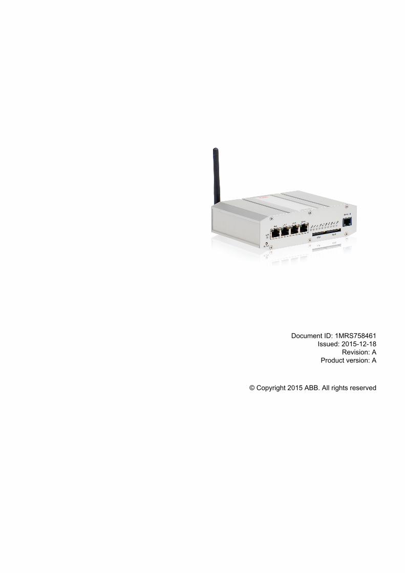
Wireless Protocol GatewayARP600 Dual SIM VariantsUser Manual

Document ID: 1MRS758461Issued: 2015-12-18
Revision: AProduct version: A
© Copyright 2015 ABB. All rights reserved

Copyright
This document and parts thereof must not be reproduced or copied without writtenpermission from ABB, and the contents thereof must not be imparted to a third party,nor used for any unauthorized purpose.
The software or hardware described in this document is furnished under a license andmay be used, copied, or disclosed only in accordance with the terms of such license.
TrademarksWarrantyPlease inquire about the terms of warranty from your nearest ABB representative.
http://www.abb.com/substationautomation
Disclaimer
The data, examples and diagrams in this manual are included solely for the concept orproduct description and are not to be deemed as a statement of guaranteed properties.All persons responsible for applying the equipment addressed in this manual mustsatisfy themselves that each intended application is suitable and acceptable, includingthat any applicable safety or other operational requirements are complied with. Inparticular, any risks in applications where a system failure and/or product failurewould create a risk for harm to property or persons (including but not limited topersonal injuries or death) shall be the sole responsibility of the person or entityapplying the equipment, and those so responsible are hereby requested to ensure thatall measures are taken to exclude or mitigate such risks.
This product has been designed to be connected and communicate data andinformation via a network interface which should be connected to a secure network.It is the sole responsibility of the person or entity responsible for networkadministration to ensure a secure connection to the network and to take the necessarymeasures (such as, but not limited to, installation of firewalls, application ofauthentication measures, encryption of data, installation of anti virus programs, etc.)to protect the product and the network, its system and interface included, against anykind of security breaches, unauthorized access, interference, intrusion, leakage and/ortheft of data or information. ABB is not liable for any such damages and/or losses.
This document has been carefully checked by ABB but deviations cannot becompletely ruled out. In case any errors are detected, the reader is kindly requested tonotify the manufacturer. Other than under explicit contractual commitments, in noevent shall ABB be responsible or liable for any loss or damage resulting from the useof this manual or the application of the equipment.

Conformity
This product complies with the directive of the Council of the European Communitieson the approximation of the laws of the Member States relating to electromagneticcompatibility (EMC Directive 2004/108/EC) and concerning electrical equipment foruse within specified voltage limits (Low-voltage directive 2006/95/EC). Thisconformity is the result of tests conducted by ABB in accordance with the productstandard EN 60255-26 for the EMC directive, and with the product standards EN60255-1 and EN 60255-27 for the low voltage directive. The product is designed inaccordance with the international standards of the IEC 60255 series.
Safety information
Dangerous voltages can occur on the connectors, even though theauxiliary voltage has been disconnected.
Non-observance can result in death, personal injury or substantialproperty damage.
Only a competent electrician is allowed to carry out the electricalinstallation.
National and local electrical safety regulations must always befollowed.
This product is not fault-tolerant and is not designed, manufactured orintended for use or resale as on-line control equipment or as part ofsuch equipment in any hazardous environment requiring fail-safeperformance, such as in the operation of nuclear facilities, aircraftnavigation or communication systems, air traffic control, direct lifesupport machines, or weapons systems, in which the failure of thehardware or software described in this manual could lead directly todeath, personal injury, or severe physical or environmental damage.
To prevent damage both the product and any terminal devices mustalways be switched off before connecting or disconnecting anycables. It should be ascertained that different devices used have thesame ground potential. The output voltage of the power supply shouldbe checked before connecting any power cables.
The devices mentioned in this manual are to be used only according tothe instructions described in this manual. Faultless and safe operationof the devices can be guaranteed only if the transport, storage,operation and handling of the devices is appropriate. This also appliesto the maintenance of the products.

User ManualWireless Protocol GatewayARP600
Firmware Version 2.4.x 2 Document Version 1
Contents
1. INTRODUCTION............................................................................................................... 41.1 About the Wireless Protocol Gateway ARP600....................................................................41.2 Wireless Protocol Gateway ARP600 features...................................................................... 41.3 Packaging information...........................................................................................................41.4 Related documentation..........................................................................................................4
2. HARDWARE DESCRIPTION............................................................................................ 62.1 Front panel............................................................................................................................ 62.2 Back Panel............................................................................................................................ 62.3 LEDs...................................................................................................................................... 7
2.3.1 Status LEDs.............................................................................................................. 72.3.2 Ethernet LEDs...........................................................................................................8
2.4 Networking.............................................................................................................................82.4.1 Mobile WAN.............................................................................................................. 82.4.2 Ethernet WAN........................................................................................................... 82.4.3 Ethernet LAN.............................................................................................................9
2.5 Serial ports............................................................................................................................ 92.5.1 Serial console port.................................................................................................... 92.5.2 Serial port 1............................................................................................................ 102.5.3 Serial port 2............................................................................................................ 11
2.6 Power switch and reset button........................................................................................... 122.7 Power connector..................................................................................................................122.8 Antenna connector.............................................................................................................. 122.9 SIM card slots..................................................................................................................... 132.10 DIN rail mounting................................................................................................................ 132.11 Product label....................................................................................................................... 13
3. QUICK INSTALLATION...................................................................................................143.1 Connection Principle............................................................................................................143.2 Connecting cables...............................................................................................................143.3 Logging in............................................................................................................................143.4 Configuring Ethernet LAN................................................................................................... 153.5 Configuring Mobile WAN (cellular network interface)......................................................... 163.6 Configuring default gateway................................................................................................16
4. NETWORK CONFIGURATION....................................................................................... 174.1 Configuration screens..........................................................................................................17
4.1.1 Host and domain names.........................................................................................174.1.2 Ethernet WAN......................................................................................................... 174.1.3 Mobile WAN............................................................................................................ 184.1.4 WAN Failover and backup routing settings............................................................ 194.1.5 Ethernet LAN...........................................................................................................194.1.6 Network monitor...................................................................................................... 19
4.2 Routing.................................................................................................................................204.2.1 Routing parameters.................................................................................................204.2.2 Default route............................................................................................................214.2.3 WAN redundancy/failover........................................................................................214.2.4 Routing serial <-> Ethernet.....................................................................................21
User ManualWireless Protocol GatewayARP600
Firmware Version 2.4.x 3 Document Version 1
4.3 Network services................................................................................................................. 214.3.1 DNS proxy...............................................................................................................21
4.4 Network status information..................................................................................................214.4.1 System status screen..............................................................................................214.4.2 Mobile WAN status LEDs....................................................................................... 224.4.3 Modem info screen................................................................................................. 22
5. SERIAL PORT CONFIGURATION................................................................................. 235.1 Configuring serial gateway..................................................................................................23
6. ADDITIONAL SYSTEM CONFIGURATION....................................................................246.1 Changing system password................................................................................................ 246.2 Date and time......................................................................................................................246.3 System log...........................................................................................................................256.4 Factory default settings....................................................................................................... 256.5 Firmware update..................................................................................................................256.6 Configuration profiles...........................................................................................................25
7. IEC-104 APPLICATION SETTINGS............................................................................... 277.1 General settings.................................................................................................................. 277.2 Serial settings......................................................................................................................287.3 Network settings..................................................................................................................297.4 IEC-104 Settings................................................................................................................. 317.5 IEC-101 settings..................................................................................................................347.6 ASDU Converter..................................................................................................................377.7 Packet collector................................................................................................................... 387.8 Other settings...................................................................................................................... 40
8. TROUBLESHOOTING.....................................................................................................41
SPECIFICATIONS .............................................................................................................. 42
User ManualWireless Protocol GatewayARP600
Firmware Version 2.4.x 4 Document Version 1
1 Introduction
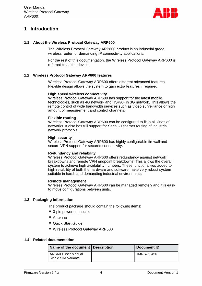
1.1 About the Wireless Protocol Gateway ARP600
The Wireless Protocol Gateway ARP600 product is an industrial gradewireless router for demanding IP connectivity applications.
For the rest of this documentation, the Wireless Protocol Gateway ARP600 isreferred to as the device.
1.2 Wireless Protocol Gateway ARP600 features
Wireless Protocol Gateway ARP600 offers different advanced features.Flexible design allows the system to gain extra features if required.
High speed wireless connectivityWireless Protocol Gateway ARP600 has support for the latest mobiletechnologies, such as 4G network and HSPA+ in 3G network. This allows theremote control of wide bandwidth services such as video surveillance or highamount of measurement and control channels.
Flexible routingWireless Protocol Gateway ARP600 can be configured to fit in all kinds ofnetworks. It also has full support for Serial - Ethernet routing of industrialnetwork protocols.
High securityWireless Protocol Gateway ARP600 has highly configurable firewall andsecure VPN support for secured connectivity.
Redundancy and reliabilityWireless Protocol Gateway ARP600 offers redundancy against networkbreakdowns and remote VPN endpoint breakdowns. This allows the overallsystem to achieve high availability numbers. These functionalities added tohigh reliability of both the hardware and software make very robust systemsuitable in harsh and demanding industrial environments.
Remote managementWireless Protocol Gateway ARP600 can be managed remotely and it is easyto move configurations between units.
1.3 Packaging information
The product package should contain the following items:■ 3-pin power connector■ Antenna■ Quick Start Guide■ Wireless Protocol Gateway ARP600
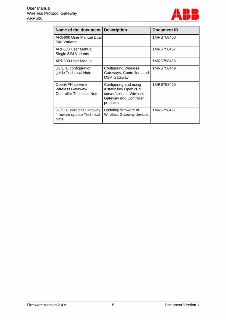
1.4 Related documentation
Name of the document Description Document ID
ARG600 User ManualSingle SIM Variants
1MRS758456
User ManualWireless Protocol GatewayARP600
Firmware Version 2.4.x 5 Document Version 1
Name of the document Description Document ID
ARG600 User Manual DualSIM Variants
1MRS758460
ARP600 User ManualSingle SIM Variants
1MRS758457
ARR600 User Manual 1MRS758458
3G/LTE configurationguide Technical Note
Configuring WirelessGateways, Controllers andM2M Gateway
1MRS758449
OpenVPN server inWireless Gateway/Controller Technical Note
Configuring and usinga static key OpenVPNserver/client in WirelessGateway and Controllerproducts
1MRS758450
3G/LTE Wireless Gatewayfirmware update TechnicalNote
Updating firmware ofWireless Gateway devices
1MRS758451
User ManualWireless Protocol GatewayARP600
Firmware Version 2.4.x 6 Document Version 1
2 Hardware description
This section describes the physical interfaces on the device.
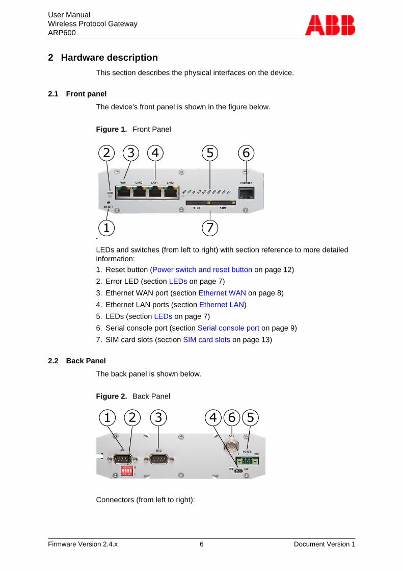
2.1 Front panel
The device's front panel is shown in the figure below.
Figure 1. Front Panel
LEDs and switches (from left to right) with section reference to more detailedinformation:
1. Reset button (Power switch and reset button on page 12)
2. Error LED (section LEDs on page 7)
3. Ethernet WAN port (section Ethernet WAN on page 8)
4. Ethernet LAN ports (section Ethernet LAN)
5. LEDs (section LEDs on page 7)
6. Serial console port (section Serial console port on page 9)
7. SIM card slots (section SIM card slots on page 13)
2.2 Back Panel
The back panel is shown below.
Figure 2. Back Panel
Connectors (from left to right):
User ManualWireless Protocol GatewayARP600
Firmware Version 2.4.x 7 Document Version 1
1. Serial port 1 (section Serial port 1 on page 10)
2. Serial port 1 configuration DIP switches (section Serial port 1 on page10)
3. Serial port 2 (section Serial port 2 on page 11)
4. Power switch
5. Power connector (section Power connector on page 12)
6. Antenna connector (section Antenna connector on page 12)
2.3 LEDs
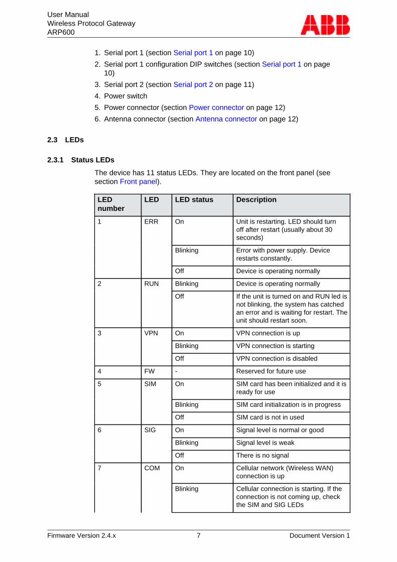
2.3.1 Status LEDs
The device has 11 status LEDs. They are located on the front panel (seesection Front panel).
LEDnumber
LED LED status Description
On Unit is restarting. LED should turnoff after restart (usually about 30seconds)
Blinking Error with power supply. Devicerestarts constantly.
1 ERR
Off Device is operating normally
Blinking Device is operating normally2 RUN
Off If the unit is turned on and RUN led isnot blinking, the system has catchedan error and is waiting for restart. Theunit should restart soon.
On VPN connection is up
Blinking VPN connection is starting
3 VPN
Off VPN connection is disabled
4 FW - Reserved for future use
On SIM card has been initialized and it isready for use
Blinking SIM card initialization is in progress
5 SIM
Off SIM card is not in used
On Signal level is normal or good
Blinking Signal level is weak
6 SIG
Off There is no signal
On Cellular network (Wireless WAN)connection is up
7 COM
Blinking Cellular connection is starting. If theconnection is not coming up, checkthe SIM and SIG LEDs
User ManualWireless Protocol GatewayARP600
Firmware Version 2.4.x 8 Document Version 1
LEDnumber
LED LED status Description
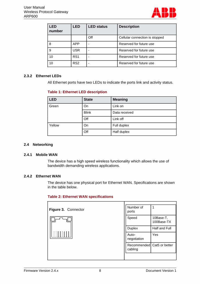
Off Cellular connection is stopped
8 APP - Reserved for future use
9 USR - Reserved for future use
10 RS1 - Reserved for future use
10 RS2 - Reserved for future use
2.3.2 Ethernet LEDs
All Ethernet ports have two LEDs to indicate the ports link and activity status.
Table 1: Ethernet LED description
LED State Meaning
On Link on
Blink Data received
Green
Off Link off
On Full duplexYellow
Off Half duplex
2.4 Networking
2.4.1 Mobile WAN
The device has a high speed wireless functionality which allows the use ofbandwidth demanding wireless applications.
2.4.2 Ethernet WAN
The device has one physical port for Ethernet WAN. Specifications are shownin the table below.
Table 2: Ethernet WAN specifications
Figure 3. ConnectorNumber ofports
1
Speed 10Base-T,100Base-TX
Duplex Half and Full
Auto-negotiation
Yes
Recommendedcabling
Cat5 or better
User ManualWireless Protocol GatewayARP600
Firmware Version 2.4.x 9 Document Version 1
If Ethernet WAN interface is directly connected to computer, crossover cablemust be used. Ethernet WAN interface does not support automatic MDI/MDIXdetection.
2.4.3 Ethernet LAN
The device has three physical ports for Ethernet LAN. These ports areconnected to a common switch. Specifications are shown in the table below.
Table 3: Ethernet LAN Specifications
Speed 10Base-T, 100Base-TX
Duplex Half and Full
Auto-negotiation Yes
Recommended cabling Cat5 or better
If Ethernet LAN interface is directly connected to computer, both crossoverand straight cables can be used. Ethernet LAN interface supports automaticMDI/MDIX detection.
2.5 Serial ports
The device has two application serial ports and one serial console port. Theapplication serial ports have the following differences:
■ Serial port 1 is configurable to multiple serial formats (RS-232/422/485).■ Serial port 2 supports only RS-232 data mode.The serial port connectors are 9-pin D-sub (male) connectors. Serial portsenact as DTE devices.
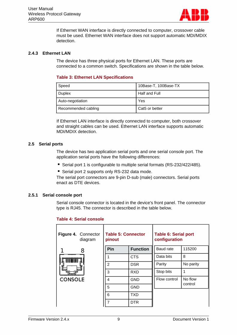
2.5.1 Serial console port
Serial console connector is located in the device's front panel. The connectortype is RJ45. The connector is described in the table below.
Table 4: Serial console
Figure 4. Connectordiagram
Table 5: Connectorpinout
Pin Function
1 CTS
2 DSR
3 RXD
4 GND
5 GND
6 TXD
7 DTR
Table 6: Serial portconfiguration
Baud rate 115200
Data bits 8
Parity No parity
Stop bits 1
Flow control No flowcontrol
User ManualWireless Protocol GatewayARP600
Firmware Version 2.4.x 10 Document Version 1
Pin Function
8 RTS
Console port can be connected from a PC by using a Cisco compatible serialconsole cable.
To open serial console access a terminal program is needed. Recommendedterminal programs are Tera Term and Putty. Open the connection usingEthernet LAN settings.
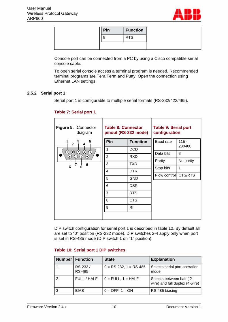
2.5.2 Serial port 1
Serial port 1 is configurable to multiple serial formats (RS-232/422/485).
Table 7: Serial port 1
Figure 5. Connectordiagram
Table 8: Connectorpinout (RS-232 mode)
Pin Function
1 DCD
2 RXD
3 TXD
4 DTR
5 GND
6 DSR
7 RTS
8 CTS
9 RI
Table 9: Serial portconfiguration
Baud rate 115 -230400
Data bits 8
Parity No parity
Stop bits 1
Flow control CTS/RTS
DIP switch configuration for serial port 1 is described in table 12. By default allare set to "0" position (RS-232 mode). DIP switches 2-4 apply only when portis set in RS-485 mode (DIP switch 1 on "1" position).
Table 10: Serial port 1 DIP switches
Number Function State Explanation
1 RS-232 /RS-485
0 = RS-232, 1 = RS-485 Selects serial port operationmode
2 FULL / HALF 0 = FULL, 1 = HALF Selects between half ( 2-wire) and full duplex (4-wire)
3 BIAS 0 = OFF, 1 = ON RS-485 biasing
User ManualWireless Protocol GatewayARP600
Firmware Version 2.4.x 11 Document Version 1
Number Function State Explanation
4 TERMINATION 0 = OFF, 1 = ON RS-485 termination
Serial port pinouts in RS-422 and RS-485 modes are described in the tablebelow.
Table 11: Serial port 1 pinouts in RS-422/485 modes
Pin RS-485 full-duplex (4-wire) RS-485 half-duplex (2-wire)
1 - -
2 RXD+ (in) -
3 TXD- (out) TXD/RXD- (out/in)
4 - -
5 GND GND
6 - -
7 TXD+ (out) TXD/RXD+ (out/in)
8 RXD- (in) -
9 - -
Note!Make sure that RS-422 or RS-485 cables are not connected to a serial portconfigured to RS-232 mode. This can damage the port and the connectedequipment.
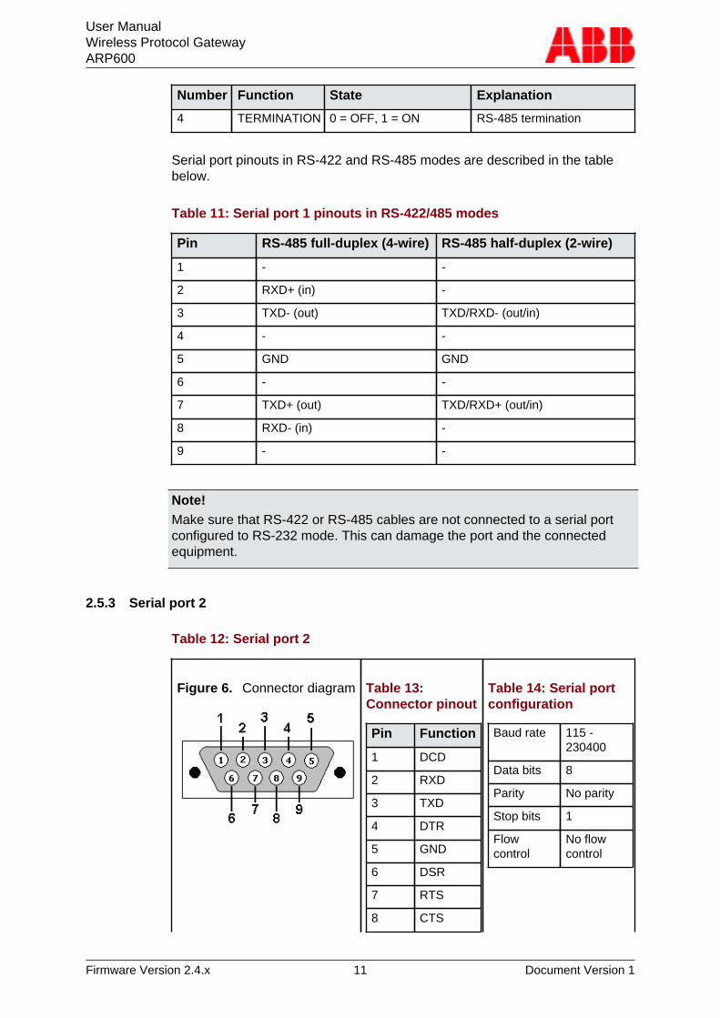
2.5.3 Serial port 2
Table 12: Serial port 2
Figure 6. Connector diagram Table 13:Connector pinout
Pin Function
1 DCD
2 RXD
3 TXD
4 DTR
5 GND
6 DSR
7 RTS
8 CTS
Table 14: Serial portconfiguration
Baud rate 115 -230400
Data bits 8
Parity No parity
Stop bits 1
Flowcontrol
No flowcontrol
User ManualWireless Protocol GatewayARP600
Firmware Version 2.4.x 12 Document Version 1
Pin Function
9 RI
Serial port 2 supports only RS-232 data mode.
2.6 Power switch and reset button
Power switch is located on the back panel. It turns the unit on and off.
Reset button is located on the front panel. Press shortly to reset the unit.Reset button can be used to restore factory default settings. To restore factorydefault settings, reset the unit by keeping the reset button pressed down untilall the status LEDs blink. This indicates the factory presets have been applied.
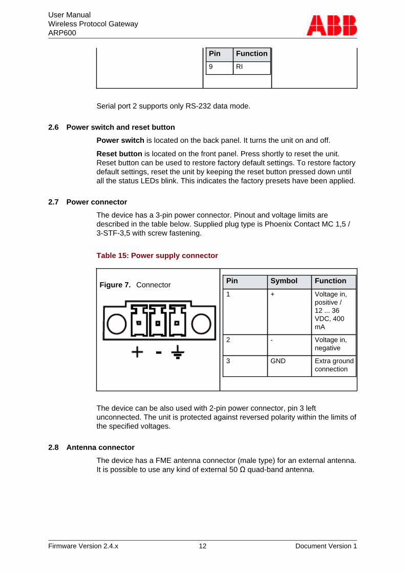
2.7 Power connector
The device has a 3-pin power connector. Pinout and voltage limits aredescribed in the table below. Supplied plug type is Phoenix Contact MC 1,5 /3-STF-3,5 with screw fastening.
Table 15: Power supply connector
Figure 7. Connector Pin Symbol Function
1 + Voltage in,positive /12 ... 36VDC, 400mA
2 - Voltage in,negative
3 GND Extra groundconnection
The device can be also used with 2-pin power connector, pin 3 leftunconnected. The unit is protected against reversed polarity within the limits ofthe specified voltages.
2.8 Antenna connector
The device has a FME antenna connector (male type) for an external antenna.It is possible to use any kind of external 50 Ω quad-band antenna.
User ManualWireless Protocol GatewayARP600
Firmware Version 2.4.x 13 Document Version 1
2.9 SIM card slots
Note!Do not insert or remove the SIM card while the device is in operation. TheSIM card contents may become corrupted if the card is removed while data isbeing written to it.
Note!If the SIM card requires a PIN code, do not install the SIM card before you setup the device's PIN code settings. The SIM card may become locked if thesettings are not made first.
The device's wireless connection requires SIM card with data transfer serviceenabled. The device can use two SIM cards, which can be used to makeconnection to two different operators. The device can be operated using onlyone SIM card.
To operate with SIM card follow the procedure below:
1. Power off the device.
2. The SIM card holder contains a tray with a yellow eject button. Push thisbutton to eject the tray from the holder.
3. Put the SIM card onto the tray.
4. Insert the tray carefully back to the holder and press the tray until it islocked.
If two SIM cards are used, repeat the procedure for SIM slot 2.
2.10 DIN rail mounting
The device has mounting holes for optional DIN rail mounting brackets.The order code for DIN rail mounting kit is 2RCA028233 (DIN rail clips setconsisting of a plastic clip and screws).
Mounting instructions:
1. Required tools and accessories are: DIN rail mounting kit (2 mountingbrackets and 4 screws), screw driver.
2. Use the screw driver to attach the screws to the bottom panel of the device.DIN rail brackets are installed to either diagonally or horisontally dependingon the wanted DIN rail installation angle.
2.11 Product label
Product label is on the bottom of the device and it contains the basicinformation about the unit such as product name, serial number and EthernetMAC address.
User ManualWireless Protocol GatewayARP600
Firmware Version 2.4.x 14 Document Version 1
3 Quick Installation
This chapter describes how to configure the WAN network interfaces on thedevice.
3.1 Connection Principle
The device has three configurable network interfaces, Ethernet WANor Ethernet LAN for a cable network, and Mobile WAN (3G) for wirelesscommunication. The WAN interfaces are used for connecting the device topublic Internet or private APN. Ethernet LAN is used for connecting otherEthernet devices to the device's local network.
The WAN interfaces can be configured to get redundant system where oneWAN automatically gets traffic if the other one goes down. For example, if theprimary Ethernet connection goes down, the traffic is automatically switchedto mobile WAN (secondary connection) and back when the Ethernet interfacecomes up again. This way the availability of the remote system is better thanwith just one interface.
3.2 Connecting cables
1. Verify that the power switch is in the OFF position.
2. Connect the Ethernet cable between the device (Ethernet LAN connector)and the computer used for the configuration.
3. Connect power supply to the device and toggle the power switch to ONposition.
4. The error LED should turn on immediately after the power switch is turnedon.
5. After the system has initialized, the Error LED turns off and the functionLED starts to blink.
3.3 Logging in
This section describes how to log in to the device using web configurationmenu.
User ManualWireless Protocol GatewayARP600
Firmware Version 2.4.x 15 Document Version 1
1. Configure the computer to use the same IP address space as the device(laptop IP for example 10.10.10.11 with netmask 255.0.0.0). Check withping command.
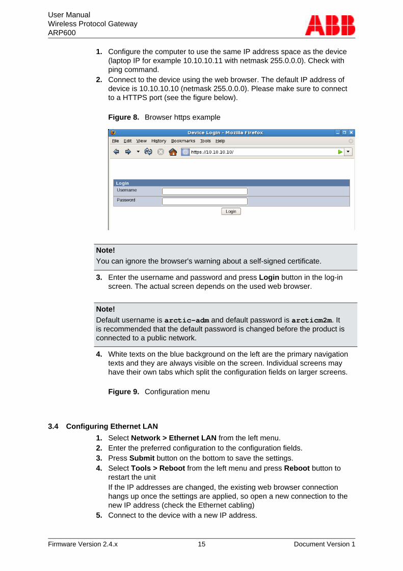
2. Connect to the device using the web browser. The default IP address ofdevice is 10.10.10.10 (netmask 255.0.0.0). Please make sure to connectto a HTTPS port (see the figure below).
Figure 8. Browser https example
Note!You can ignore the browser's warning about a self-signed certificate.
3. Enter the username and password and press Login button in the log-inscreen. The actual screen depends on the used web browser.
Note!Default username is arctic-adm and default password is arcticm2m. Itis recommended that the default password is changed before the product isconnected to a public network.
4. White texts on the blue background on the left are the primary navigationtexts and they are always visible on the screen. Individual screens mayhave their own tabs which split the configuration fields on larger screens.
Figure 9. Configuration menu
3.4 Configuring Ethernet LAN
1. Select Network > Ethernet LAN from the left menu.2. Enter the preferred configuration to the configuration fields.3. Press Submit button on the bottom to save the settings.4. Select Tools > Reboot from the left menu and press Reboot button to
restart the unitIf the IP addresses are changed, the existing web browser connectionhangs up once the settings are applied, so open a new connection to thenew IP address (check the Ethernet cabling)
5. Connect to the device with a new IP address.
User ManualWireless Protocol GatewayARP600
Firmware Version 2.4.x 16 Document Version 1
3.5 Configuring Mobile WAN (cellular network interface)
The Mobile WAN interface is used for connecting the device to a cellularnetwork. The device can use a GPRS (2G), UMTS (3G) or LTE (4G) cellularnetwork connection depending on the product model.
Install the SIM card before configuring the Mobile WAN. See Back PanelDescription for the location of the SIM card slot.
1. Select Network > Mobile WAN from the left menu.
2. Enter the preferred configuration to the configuration fields.
3. Press Submit on the bottom to save the settings.
3.6 Configuring default gateway
1. Select Network WAN Failover from the left menu.
2. Set "WAN Default Route"="Yes". This has to be enabled to use eitherWAN as default route interface.
3. If the mobile WAN has to be set as a default gateway, set "Primary WANInterface"="Mobile WAN".This is a typical setting.
4. If Ethernet WAN has to be set as a default gateway:
a) Select Network > Ethernet port settings > WAN .b) Set "PrimaryWAN Interface"="EthernetWAN"
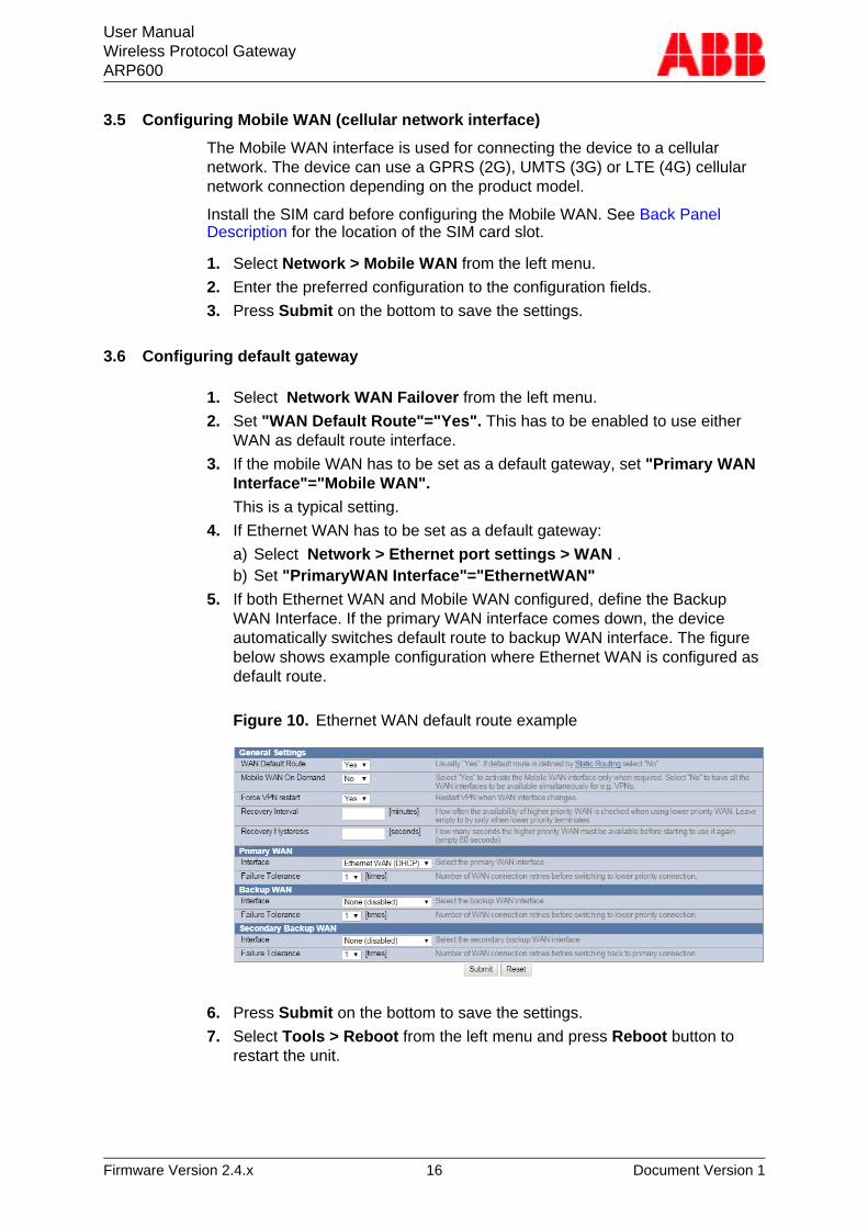
5. If both Ethernet WAN and Mobile WAN configured, define the BackupWAN Interface. If the primary WAN interface comes down, the deviceautomatically switches default route to backup WAN interface. The figurebelow shows example configuration where Ethernet WAN is configured asdefault route.
Figure 10. Ethernet WAN default route example
6. Press Submit on the bottom to save the settings.
7. Select Tools > Reboot from the left menu and press Reboot button torestart the unit.
User ManualWireless Protocol GatewayARP600
Firmware Version 2.4.x 17 Document Version 1
4 Network Configuration
This chapter describes how to configure network interfaces.
4.1 Configuration screens
The web user interface has a navigation menu that is always visible on theleft pane. In the menu, the items are grouped together in sections such asSystem, Network, VPN and Firewall.
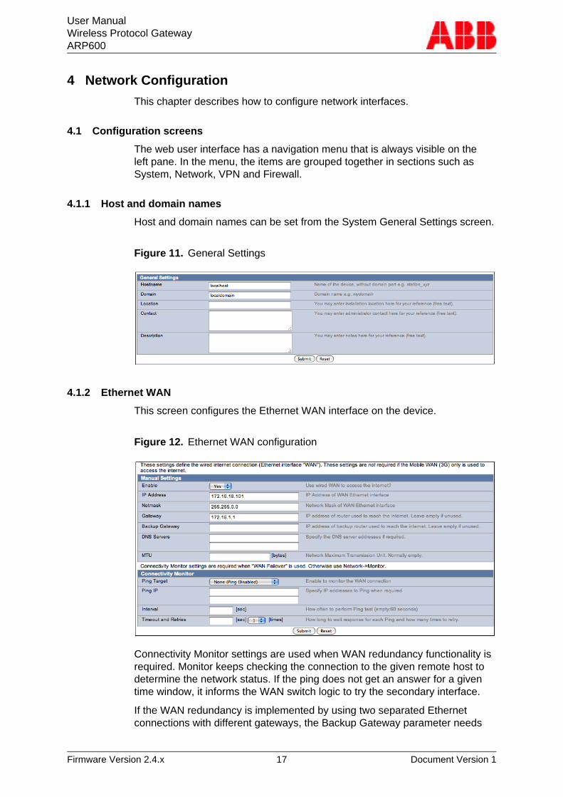
4.1.1 Host and domain names
Host and domain names can be set from the System General Settings screen.
Figure 11. General Settings
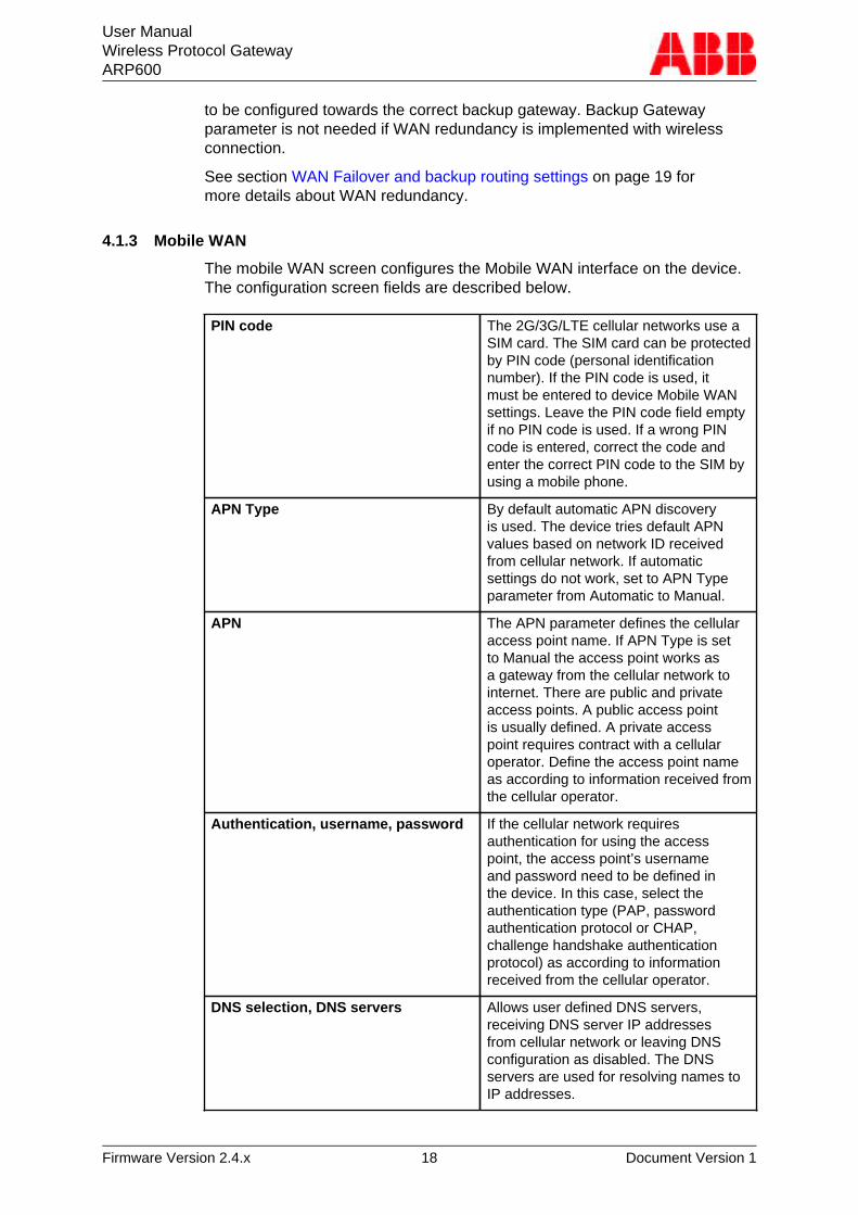
4.1.2 Ethernet WAN
This screen configures the Ethernet WAN interface on the device.
Figure 12. Ethernet WAN configuration
Connectivity Monitor settings are used when WAN redundancy functionality isrequired. Monitor keeps checking the connection to the given remote host todetermine the network status. If the ping does not get an answer for a giventime window, it informs the WAN switch logic to try the secondary interface.
If the WAN redundancy is implemented by using two separated Ethernetconnections with different gateways, the Backup Gateway parameter needs
User ManualWireless Protocol GatewayARP600
Firmware Version 2.4.x 18 Document Version 1
to be configured towards the correct backup gateway. Backup Gatewayparameter is not needed if WAN redundancy is implemented with wirelessconnection.
See section WAN Failover and backup routing settings on page 19 formore details about WAN redundancy.
4.1.3 Mobile WAN
The mobile WAN screen configures the Mobile WAN interface on the device.The configuration screen fields are described below.
PIN code The 2G/3G/LTE cellular networks use aSIM card. The SIM card can be protectedby PIN code (personal identificationnumber). If the PIN code is used, itmust be entered to device Mobile WANsettings. Leave the PIN code field emptyif no PIN code is used. If a wrong PINcode is entered, correct the code andenter the correct PIN code to the SIM byusing a mobile phone.
APN Type By default automatic APN discoveryis used. The device tries default APNvalues based on network ID receivedfrom cellular network. If automaticsettings do not work, set to APN Typeparameter from Automatic to Manual.
APN The APN parameter defines the cellularaccess point name. If APN Type is setto Manual the access point works asa gateway from the cellular network tointernet. There are public and privateaccess points. A public access pointis usually defined. A private accesspoint requires contract with a cellularoperator. Define the access point nameas according to information received fromthe cellular operator.
Authentication, username, password If the cellular network requiresauthentication for using the accesspoint, the access point’s usernameand password need to be defined inthe device. In this case, select theauthentication type (PAP, passwordauthentication protocol or CHAP,challenge handshake authenticationprotocol) as according to informationreceived from the cellular operator.
DNS selection, DNS servers Allows user defined DNS servers,receiving DNS server IP addressesfrom cellular network or leaving DNSconfiguration as disabled. The DNSservers are used for resolving names toIP addresses.
User ManualWireless Protocol GatewayARP600
Firmware Version 2.4.x 19 Document Version 1
To configure the mobile WAN, enable the connection by selecting"Enable"="Yes" on the top of the page and enter PIN code if set, APN nameand authentication details if needed.
If the device acts as a wireless router to Ethernet devices and DNS is needed,enter DNS configuration as well. When ready, press the Submit button on thebottom of the page to save settings.
The device needs to be restarted before the mobile WAN configuration isactive.
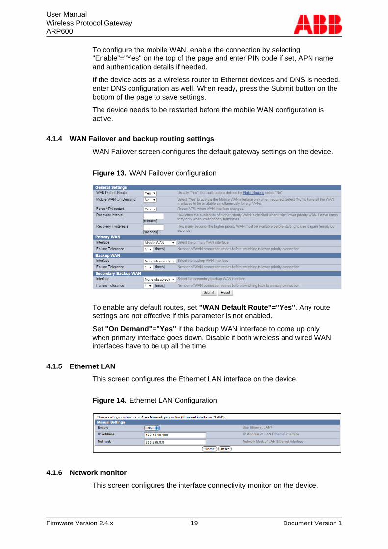
4.1.4 WAN Failover and backup routing settings
WAN Failover screen configures the default gateway settings on the device.
Figure 13. WAN Failover configuration
To enable any default routes, set "WAN Default Route"="Yes". Any routesettings are not effective if this parameter is not enabled.
Set "On Demand"="Yes" if the backup WAN interface to come up onlywhen primary interface goes down. Disable if both wireless and wired WANinterfaces have to be up all the time.
4.1.5 Ethernet LAN
This screen configures the Ethernet LAN interface on the device.
Figure 14. Ethernet LAN Configuration
4.1.6 Network monitor
This screen configures the interface connectivity monitor on the device.
User ManualWireless Protocol GatewayARP600
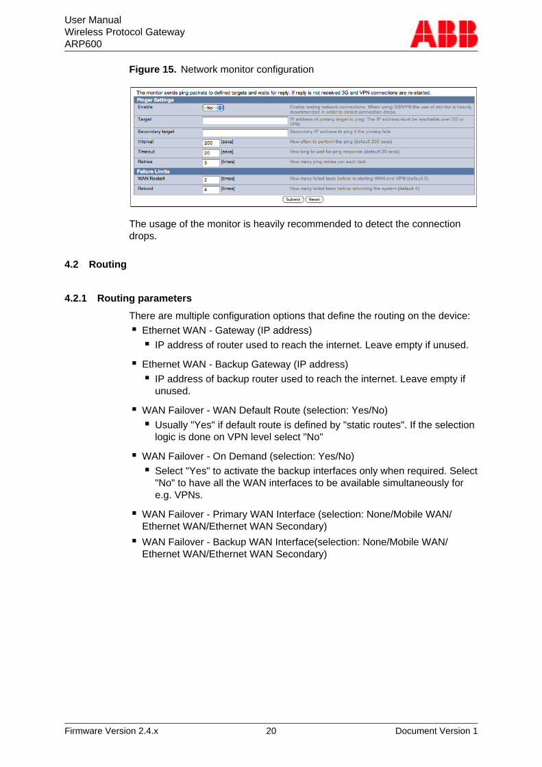
Firmware Version 2.4.x 20 Document Version 1
Figure 15. Network monitor configuration
The usage of the monitor is heavily recommended to detect the connectiondrops.
4.2 Routing
4.2.1 Routing parameters
There are multiple configuration options that define the routing on the device:■ Ethernet WAN - Gateway (IP address)
■ IP address of router used to reach the internet. Leave empty if unused.
■ Ethernet WAN - Backup Gateway (IP address)■ IP address of backup router used to reach the internet. Leave empty if
unused.
■ WAN Failover - WAN Default Route (selection: Yes/No)■ Usually "Yes" if default route is defined by "static routes". If the selection
logic is done on VPN level select "No"
■ WAN Failover - On Demand (selection: Yes/No)■ Select "Yes" to activate the backup interfaces only when required. Select
"No" to have all the WAN interfaces to be available simultaneously fore.g. VPNs.
■ WAN Failover - Primary WAN Interface (selection: None/Mobile WAN/Ethernet WAN/Ethernet WAN Secondary)
■ WAN Failover - Backup WAN Interface(selection: None/Mobile WAN/Ethernet WAN/Ethernet WAN Secondary)
User ManualWireless Protocol GatewayARP600
Firmware Version 2.4.x 21 Document Version 1
■ WAN Failover - Secondary Backup WAN Interface (selection: None/MobileWAN/Ethernet WAN/Ethernet WAN Secondary)■ These three settings configure the high level default gateways. Must be
configured to enable default route.
■ OpenVPN Client Settings - Interface (selection: Any WAN/Ethernet WAN/Wireless WAN/Ethernet LAN)■ Which Interface to use for connection
■ OpenVPN Client Settings - Routing mode (selection: None/host/net/defaultroute)■ This defines how the routing is configured with OpenVPN. See
OpenVPN application note.
4.2.2 Default route
Default route can be configured from WAN Failover screen. See section WANFailover and backup routing settings on page 19.
4.2.3 WAN redundancy/failover
To configure redundancy between WAN interfaces, configure multiple WANinterfaces to WAN Failover. See section WAN Failover and backup routingsettings on page 19.
4.2.4 Routing serial <-> Ethernet
See section Serial Port Configuration on page 23.
4.3 Network services
4.3.1 DNS proxy
To use this feature, configure the device to use the device's Ethernet LAN IPaddress as its DNS server. This way, the DNS queries from the device getrouted through the device.
4.4 Network status information
4.4.1 System status screen
Network status information can be seen from System > Status screen .
User ManualWireless Protocol GatewayARP600
Firmware Version 2.4.x 22 Document Version 1
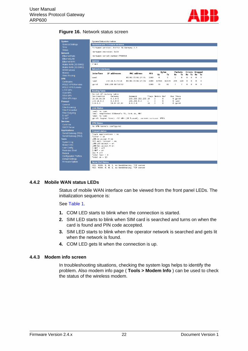
Figure 16. Network status screen
4.4.2 Mobile WAN status LEDs
Status of mobile WAN interface can be viewed from the front panel LEDs. Theinitialization sequence is:
See Table 1.
1. COM LED starts to blink when the connection is started.
2. SIM LED starts to blink when SIM card is searched and turns on when thecard is found and PIN code accepted.
3. SIM LED starts to blink when the operator network is searched and gets litwhen the network is found.
4. COM LED gets lit when the connection is up.
4.4.3 Modem info screen
In troubleshooting situations, checking the system logs helps to identify theproblem. Also modem info page ( Tools > Modem Info ) can be used to checkthe status of the wireless modem.
User ManualWireless Protocol GatewayARP600
Firmware Version 2.4.x 23 Document Version 1
5 Serial Port Configuration
5.1 Configuring serial gateway
This section describes how to configure serial <-> IP functionality.
The serial gateway feature enables data from the serial port attached deviceto be routed to Ethernet/mobile network (serial over IP) and vice versa. Serialgateway processes the transmitted data transparently and does not alter itany way except for buffering it for transmission. Because of the transparentcommunication, any protocols can be used in actual communication betweennodes.
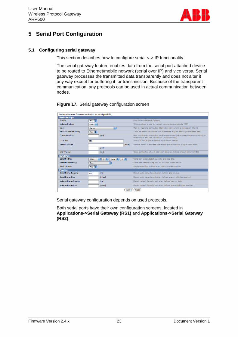
Figure 17. Serial gateway configuration screen
Serial gateway configuration depends on used protocols.
Both serial ports have their own configuration screens, located inApplications->Serial Gateway (RS1) and Applications->Serial Gateway(RS2).
User ManualWireless Protocol GatewayARP600
Firmware Version 2.4.x 24 Document Version 1
6 Additional System Configuration
6.1 Changing system password
Username and password can be changed from Tools > User Config screen.It is always recommended to change the password from the factory defaultwhen the device is connected to a public network.
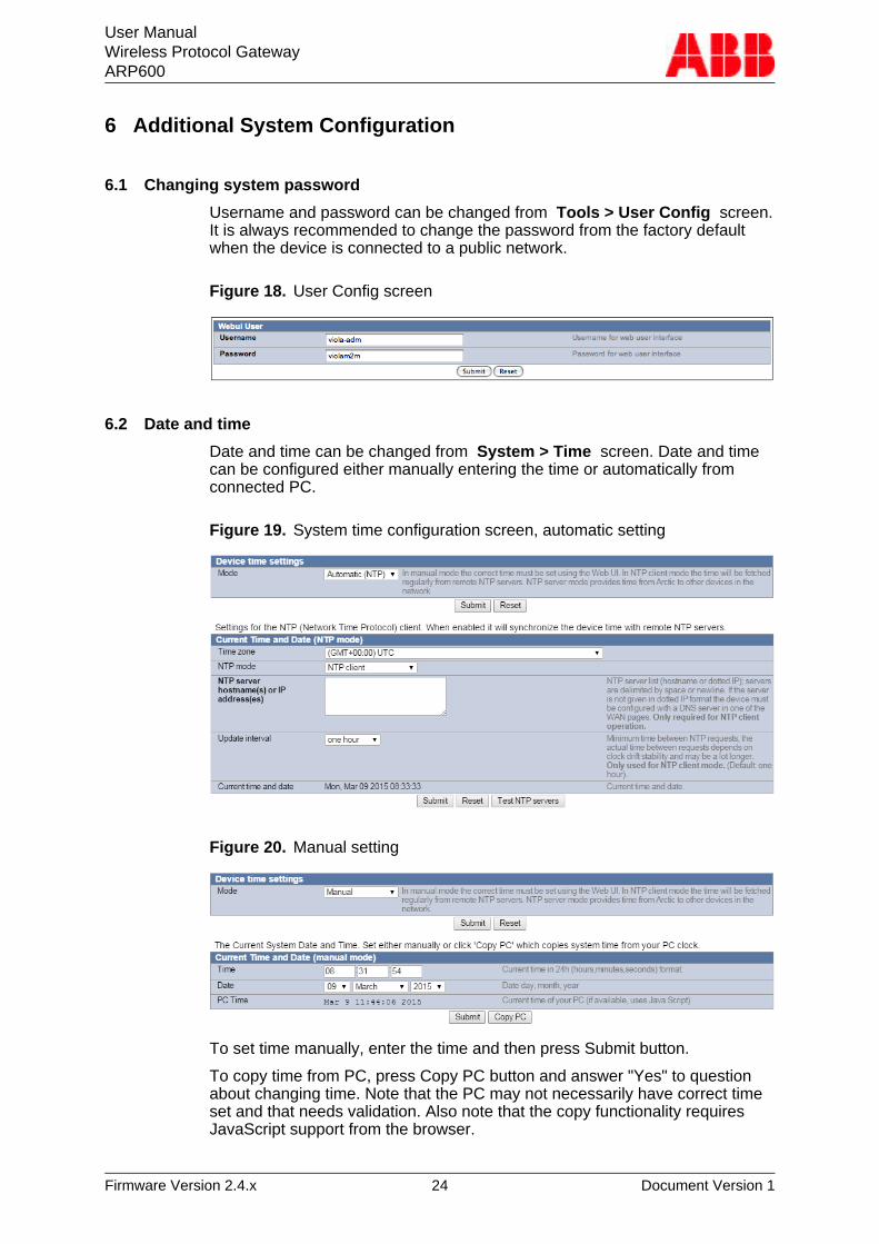
Figure 18. User Config screen
6.2 Date and time
Date and time can be changed from System > Time screen. Date and timecan be configured either manually entering the time or automatically fromconnected PC.
Figure 19. System time configuration screen, automatic setting
Figure 20. Manual setting
To set time manually, enter the time and then press Submit button.
To copy time from PC, press Copy PC button and answer "Yes" to questionabout changing time. Note that the PC may not necessarily have correct timeset and that needs validation. Also note that the copy functionality requiresJavaScript support from the browser.
User ManualWireless Protocol GatewayARP600
Firmware Version 2.4.x 25 Document Version 1
6.3 System log
System log is visible on the Tools > System Log screen. To refresh thesystem log, use web browser reload button.
6.4 Factory default settings
Factory default settings can be applied by restarting the unit pressing downreset button until the LEDs blink.
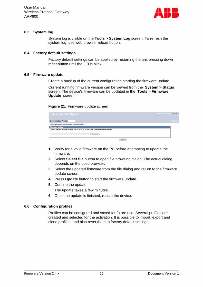
6.5 Firmware update
Create a backup of the current configuration starting the firmware update.
Current running firmware version can be viewed from the System > Status screen. The device's firmware can be updated in the Tools > FirmwareUpdate screen.
Figure 21. Firmware update screen
1. Verify for a valid firmware on the PC before attempting to update thefirmware.
2. Select Select file button to open file browsing dialog. The actual dialogdepends on the used browser.
3. Select the updated firmware from the file dialog and return to the firmwareupdate screen.
4. Press Update button to start the firmware update.
5. Confirm the update.
The update takes a few minutes.
6. Once the update is finished, restart the device.
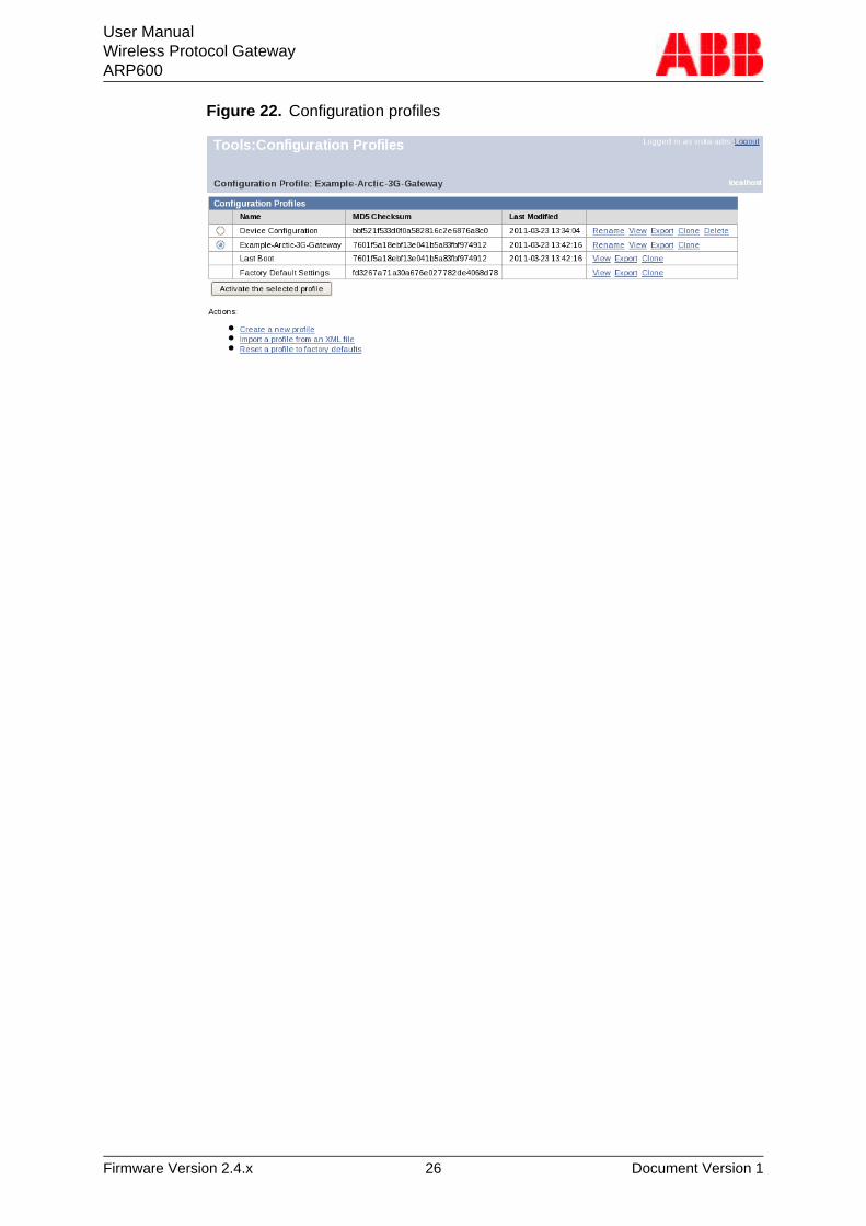
6.6 Configuration profiles
Profiles can be configured and saved for future use. Several profiles arecreated and selected for the activation. It is possible to import, export andclone profiles, and also reset them to factory default settings.
User ManualWireless Protocol GatewayARP600
Firmware Version 2.4.x 26 Document Version 1
Figure 22. Configuration profiles
User ManualWireless Protocol GatewayARP600
Firmware Version 2.4.x 27 Document Version 1
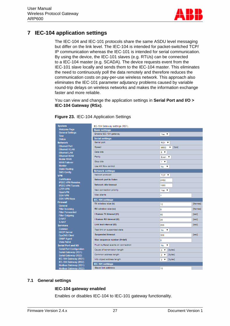
7 IEC-104 application settings
The IEC-104 and IEC-101 protocols share the same ASDU level messagingbut differ on the link level. The IEC-104 is intended for packet-switched TCP/IP communication whereas the IEC-101 is intended for serial communication.By using the device, the IEC-101 slaves (e.g. RTUs) can be connectedto a IEC-104 master (e.g. SCADA). The device requests event from theIEC-101 slave locally and sends them to the IEC-104 master. This eliminatesthe need to continuously poll the data remotely and therefore reduces thecommunication costs on pay-per-use wireless network. This approach alsoeliminates the IEC-101 parameter adjutancy problems caused by variableround-trip delays on wireless networks and makes the information exchangefaster and more reliable.
You can view and change the application settings in Serial Port and I/O >IEC-104 Gateway (RSx).
Figure 23. IEC-104 Application Settings
7.1 General settings
IEC-104 gateway enabled
Enables or disables IEC-104 to IEC-101 gateway functionality.
User ManualWireless Protocol GatewayARP600
Firmware Version 2.4.x 28 Document Version 1
Table 16: IEC-104 gateway enabled
IEC-104 gateway enabled
Type Boolean
Units N/A
Value range No, Yes
Note
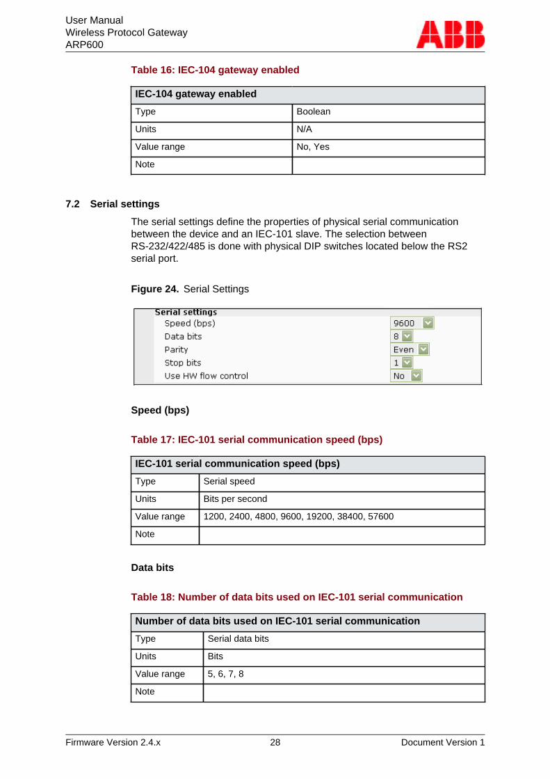
7.2 Serial settings
The serial settings define the properties of physical serial communicationbetween the device and an IEC-101 slave. The selection betweenRS-232/422/485 is done with physical DIP switches located below the RS2serial port.
Figure 24. Serial Settings
Speed (bps)
Table 17: IEC-101 serial communication speed (bps)
IEC-101 serial communication speed (bps)
Type Serial speed
Units Bits per second
Value range 1200, 2400, 4800, 9600, 19200, 38400, 57600
Note
Data bits
Table 18: Number of data bits used on IEC-101 serial communication
Number of data bits used on IEC-101 serial communication
Type Serial data bits
Units Bits
Value range 5, 6, 7, 8
Note
User ManualWireless Protocol GatewayARP600
Firmware Version 2.4.x 29 Document Version 1
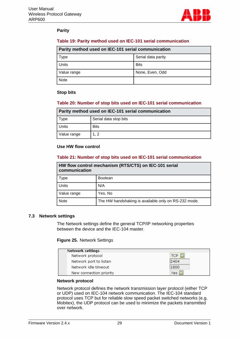
Parity
Table 19: Parity method used on IEC-101 serial communication
Parity method used on IEC-101 serial communication
Type Serial data parity
Units Bits
Value range None, Even, Odd
Note
Stop bits
Table 20: Number of stop bits used on IEC-101 serial communication
Parity method used on IEC-101 serial communication
Type Serial data stop bits
Units Bits
Value range 1, 2
Use HW flow control
Table 21: Number of stop bits used on IEC-101 serial communication
HW flow control mechanism (RTS/CTS) on IEC-101 serialcommunication
Type Boolean
Units N/A
Value range Yes, No
Note The HW handshaking is available only on RS-232 mode.
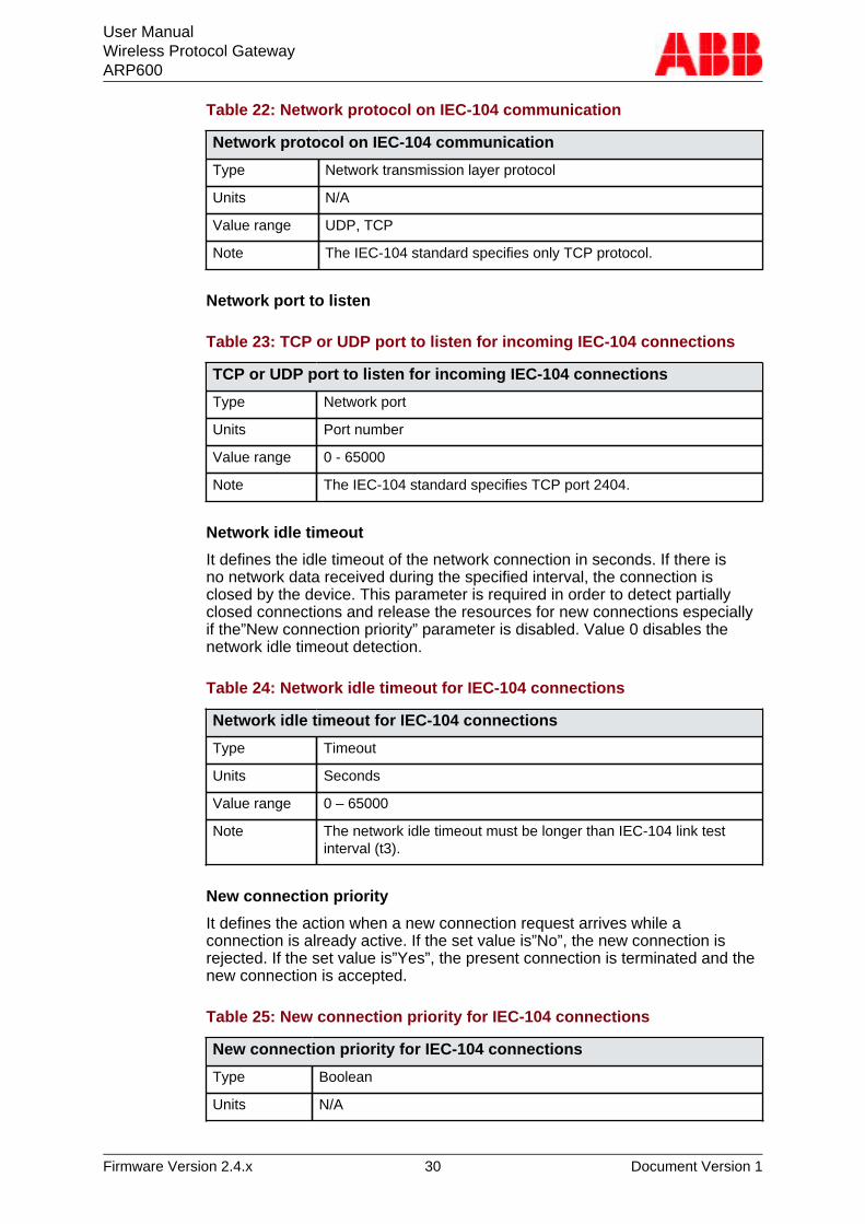
7.3 Network settings
The Network settings define the general TCP/IP networking propertiesbetween the device and the IEC-104 master.
Figure 25. Network Settings
Network protocol
Network protocol defines the network transmission layer protocol (either TCPor UDP) used on IEC-104 network communication. The IEC-104 standardprotocol uses TCP but for reliable slow speed packet switched networks (e.g.Mobitex), the UDP protocol can be used to minimize the packets transmittedover network.
User ManualWireless Protocol GatewayARP600
Firmware Version 2.4.x 30 Document Version 1
Table 22: Network protocol on IEC-104 communication
Network protocol on IEC-104 communication
Type Network transmission layer protocol
Units N/A
Value range UDP, TCP
Note The IEC-104 standard specifies only TCP protocol.
Network port to listen
Table 23: TCP or UDP port to listen for incoming IEC-104 connections
TCP or UDP port to listen for incoming IEC-104 connections
Type Network port
Units Port number
Value range 0 - 65000
Note The IEC-104 standard specifies TCP port 2404.
Network idle timeout
It defines the idle timeout of the network connection in seconds. If there isno network data received during the specified interval, the connection isclosed by the device. This parameter is required in order to detect partiallyclosed connections and release the resources for new connections especiallyif the”New connection priority” parameter is disabled. Value 0 disables thenetwork idle timeout detection.
Table 24: Network idle timeout for IEC-104 connections
Network idle timeout for IEC-104 connections
Type Timeout
Units Seconds
Value range 0 – 65000
Note The network idle timeout must be longer than IEC-104 link testinterval (t3).
New connection priority
It defines the action when a new connection request arrives while aconnection is already active. If the set value is”No”, the new connection isrejected. If the set value is”Yes”, the present connection is terminated and thenew connection is accepted.
Table 25: New connection priority for IEC-104 connections
New connection priority for IEC-104 connections
Type Boolean
Units N/A
User ManualWireless Protocol GatewayARP600
Firmware Version 2.4.x 31 Document Version 1
New connection priority for IEC-104 connections
Value range No, Yes
Note It is recommendable to set this value to “Yes” in normalconfigurations having only one IEC-104 master.
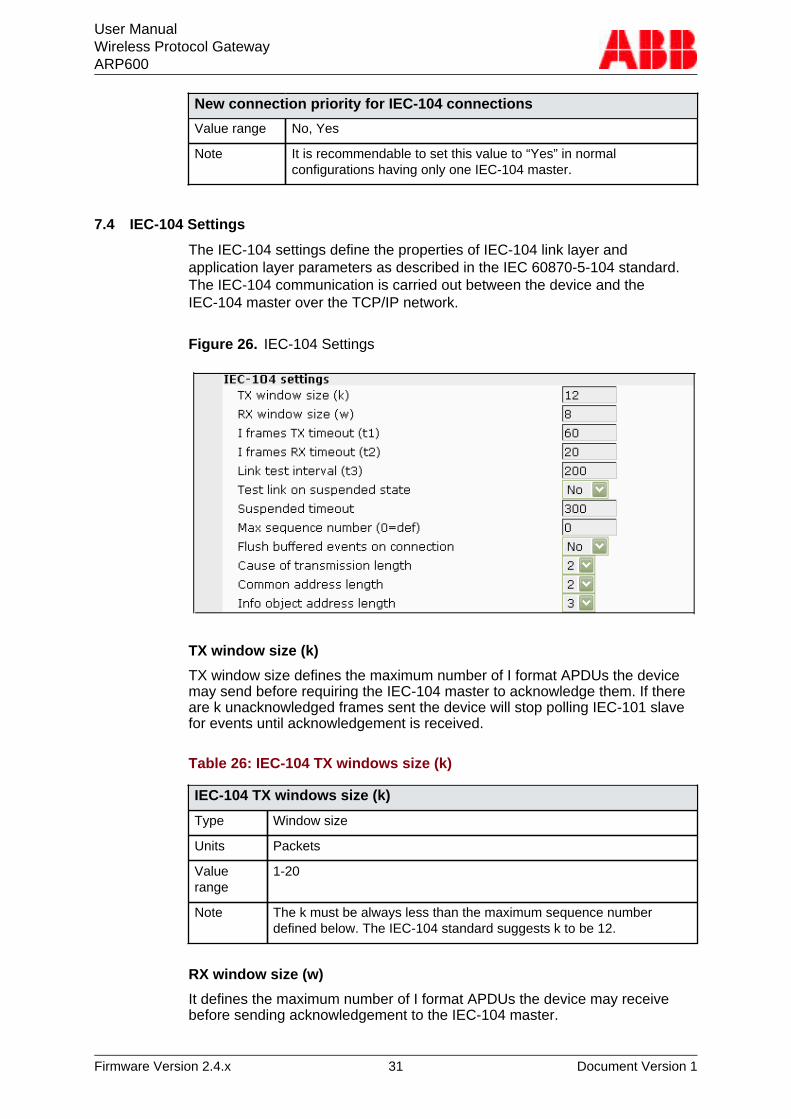
7.4 IEC-104 Settings
The IEC-104 settings define the properties of IEC-104 link layer andapplication layer parameters as described in the IEC 60870-5-104 standard.The IEC-104 communication is carried out between the device and theIEC-104 master over the TCP/IP network.
Figure 26. IEC-104 Settings
TX window size (k)
TX window size defines the maximum number of I format APDUs the devicemay send before requiring the IEC-104 master to acknowledge them. If thereare k unacknowledged frames sent the device will stop polling IEC-101 slavefor events until acknowledgement is received.
Table 26: IEC-104 TX windows size (k)
IEC-104 TX windows size (k)
Type Window size
Units Packets
Valuerange
1-20
Note The k must be always less than the maximum sequence numberdefined below. The IEC-104 standard suggests k to be 12.
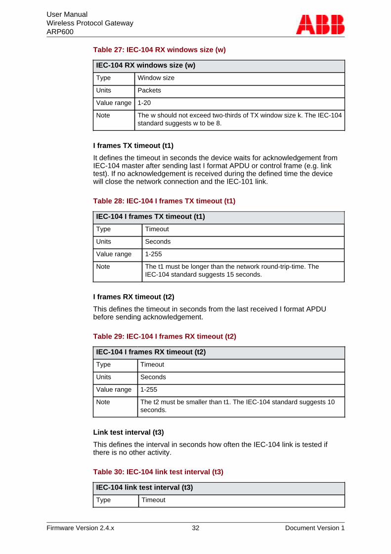
RX window size (w)
It defines the maximum number of I format APDUs the device may receivebefore sending acknowledgement to the IEC-104 master.
User ManualWireless Protocol GatewayARP600
Firmware Version 2.4.x 32 Document Version 1
Table 27: IEC-104 RX windows size (w)
IEC-104 RX windows size (w)
Type Window size
Units Packets
Value range 1-20
Note The w should not exceed two-thirds of TX window size k. The IEC-104standard suggests w to be 8.
I frames TX timeout (t1)
It defines the timeout in seconds the device waits for acknowledgement fromIEC-104 master after sending last I format APDU or control frame (e.g. linktest). If no acknowledgement is received during the defined time the devicewill close the network connection and the IEC-101 link.
Table 28: IEC-104 I frames TX timeout (t1)
IEC-104 I frames TX timeout (t1)
Type Timeout
Units Seconds
Value range 1-255
Note The t1 must be longer than the network round-trip-time. TheIEC-104 standard suggests 15 seconds.
I frames RX timeout (t2)
This defines the timeout in seconds from the last received I format APDUbefore sending acknowledgement.
Table 29: IEC-104 I frames RX timeout (t2)
IEC-104 I frames RX timeout (t2)
Type Timeout
Units Seconds
Value range 1-255
Note The t2 must be smaller than t1. The IEC-104 standard suggests 10seconds.
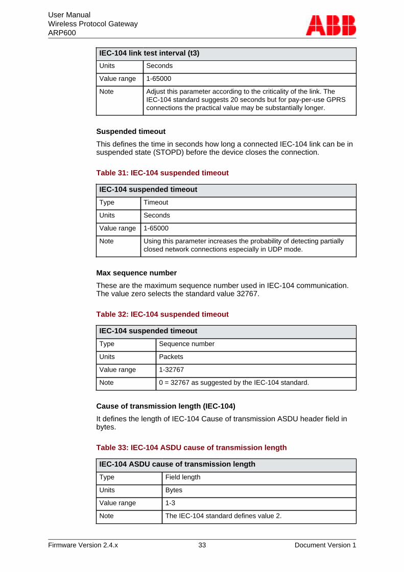
Link test interval (t3)
This defines the interval in seconds how often the IEC-104 link is tested ifthere is no other activity.
Table 30: IEC-104 link test interval (t3)
IEC-104 link test interval (t3)
Type Timeout
User ManualWireless Protocol GatewayARP600
Firmware Version 2.4.x 33 Document Version 1
IEC-104 link test interval (t3)
Units Seconds
Value range 1-65000
Note Adjust this parameter according to the criticality of the link. TheIEC-104 standard suggests 20 seconds but for pay-per-use GPRSconnections the practical value may be substantially longer.
Suspended timeout
This defines the time in seconds how long a connected IEC-104 link can be insuspended state (STOPD) before the device closes the connection.
Table 31: IEC-104 suspended timeout
IEC-104 suspended timeout
Type Timeout
Units Seconds
Value range 1-65000
Note Using this parameter increases the probability of detecting partiallyclosed network connections especially in UDP mode.
Max sequence number
These are the maximum sequence number used in IEC-104 communication.The value zero selects the standard value 32767.
Table 32: IEC-104 suspended timeout
IEC-104 suspended timeout
Type Sequence number
Units Packets
Value range 1-32767
Note 0 = 32767 as suggested by the IEC-104 standard.
Cause of transmission length (IEC-104)
It defines the length of IEC-104 Cause of transmission ASDU header field inbytes.
Table 33: IEC-104 ASDU cause of transmission length
IEC-104 ASDU cause of transmission length
Type Field length
Units Bytes
Value range 1-3
Note The IEC-104 standard defines value 2.
User ManualWireless Protocol GatewayARP600
Firmware Version 2.4.x 34 Document Version 1
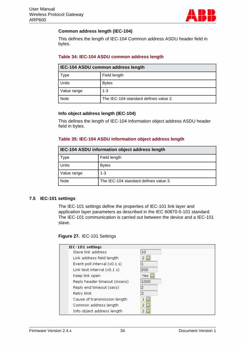
Common address length (IEC-104)
This defines the length of IEC-104 Common address ASDU header field inbytes.
Table 34: IEC-104 ASDU common address length
IEC-104 ASDU common address length
Type Field length
Units Bytes
Value range 1-3
Note The IEC-104 standard defines value 2.
Info object address length (IEC-104)
This defines the length of IEC-104 Information object address ASDU headerfield in bytes.
Table 35: IEC-104 ASDU information object address length
IEC-104 ASDU information object address length
Type Field length
Units Bytes
Value range 1-3
Note The IEC-104 standard defines value 3.
7.5 IEC-101 settings
The IEC-101 settings define the properties of IEC-101 link layer andapplication layer parameters as described in the IEC 60870-5-101 standard.The IEC-101 communication is carried out between the device and a IEC-101slave.
Figure 27. IEC-101 Settings
User ManualWireless Protocol GatewayARP600
Firmware Version 2.4.x 35 Document Version 1
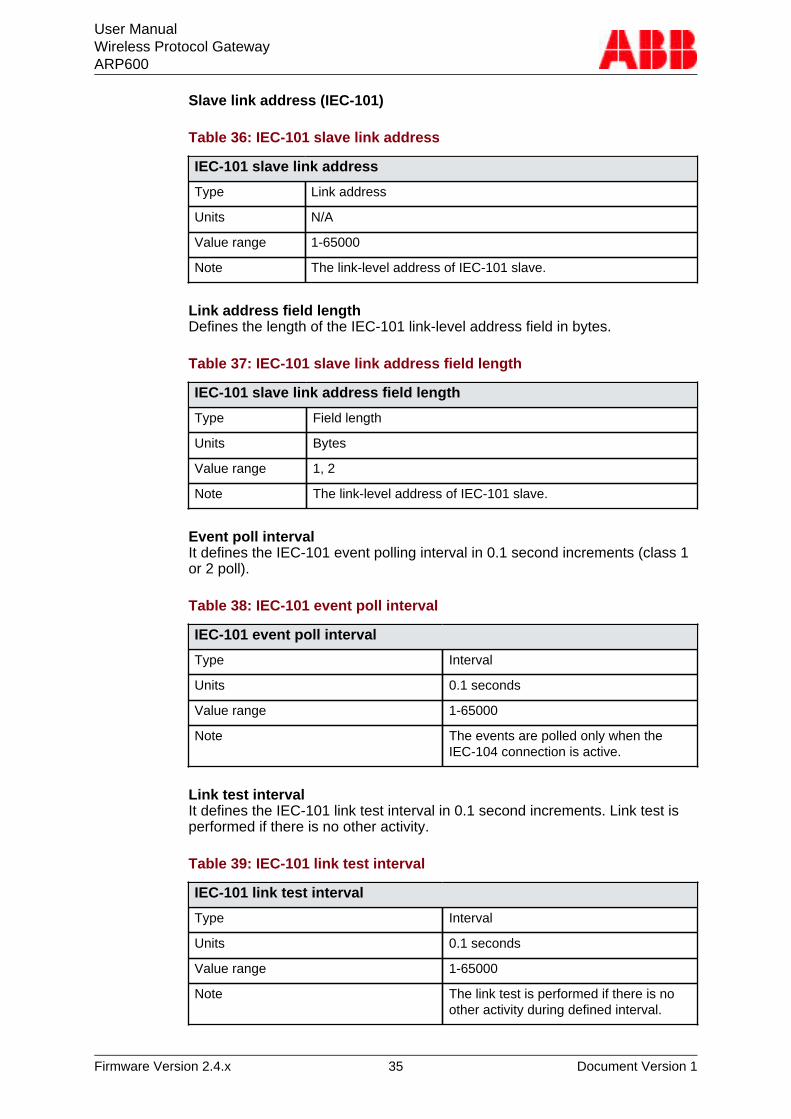
Slave link address (IEC-101)
Table 36: IEC-101 slave link address
IEC-101 slave link address
Type Link address
Units N/A
Value range 1-65000
Note The link-level address of IEC-101 slave.
Link address field lengthDefines the length of the IEC-101 link-level address field in bytes.
Table 37: IEC-101 slave link address field length
IEC-101 slave link address field length
Type Field length
Units Bytes
Value range 1, 2
Note The link-level address of IEC-101 slave.
Event poll intervalIt defines the IEC-101 event polling interval in 0.1 second increments (class 1or 2 poll).
Table 38: IEC-101 event poll interval
IEC-101 event poll interval
Type Interval
Units 0.1 seconds
Value range 1-65000
Note The events are polled only when theIEC-104 connection is active.
Link test intervalIt defines the IEC-101 link test interval in 0.1 second increments. Link test isperformed if there is no other activity.
Table 39: IEC-101 link test interval
IEC-101 link test interval
Type Interval
Units 0.1 seconds
Value range 1-65000
Note The link test is performed if there is noother activity during defined interval.
User ManualWireless Protocol GatewayARP600
Firmware Version 2.4.x 36 Document Version 1
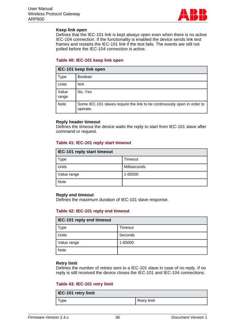
Keep link openDefines that the IEC-101 link is kept always open even when there is no activeIEC-104 connection. If the functionality is enabled the device sends link testframes and restarts the IEC-101 link if the test fails. The events are still notpolled before the IEC-104 connection is active.
Table 40: IEC-101 keep link open
IEC-101 keep link open
Type Boolean
Units N/A
Valuerange
No, Yes
Note Some IEC-101 slaves require the link to be continuously open in order tooperate.
Reply header timeoutDefines the timeout the device waits the reply to start from IEC-101 slave aftercommand or request.
Table 41: IEC-101 reply start timeout
IEC-101 reply start timeout
Type Timeout
Units Milliseconds
Value range 1-65000
Note
Reply end timeoutDefines the maximum duration of IEC-101 slave response.
Table 42: IEC-101 reply end timeout
IEC-101 reply end timeout
Type Timeout
Units Seconds
Value range 1-65000
Note
Retry limitDefines the number of retries sent to a IEC-101 slave in case of no reply. If noreply is still received the device closes the IEC-101 and IEC-104 connections.
Table 43: IEC-101 retry limit
IEC-101 retry limit
Type Retry limit
User ManualWireless Protocol GatewayARP600
Firmware Version 2.4.x 37 Document Version 1
IEC-101 retry limit
Units Retries
Value range 0-65000
Note
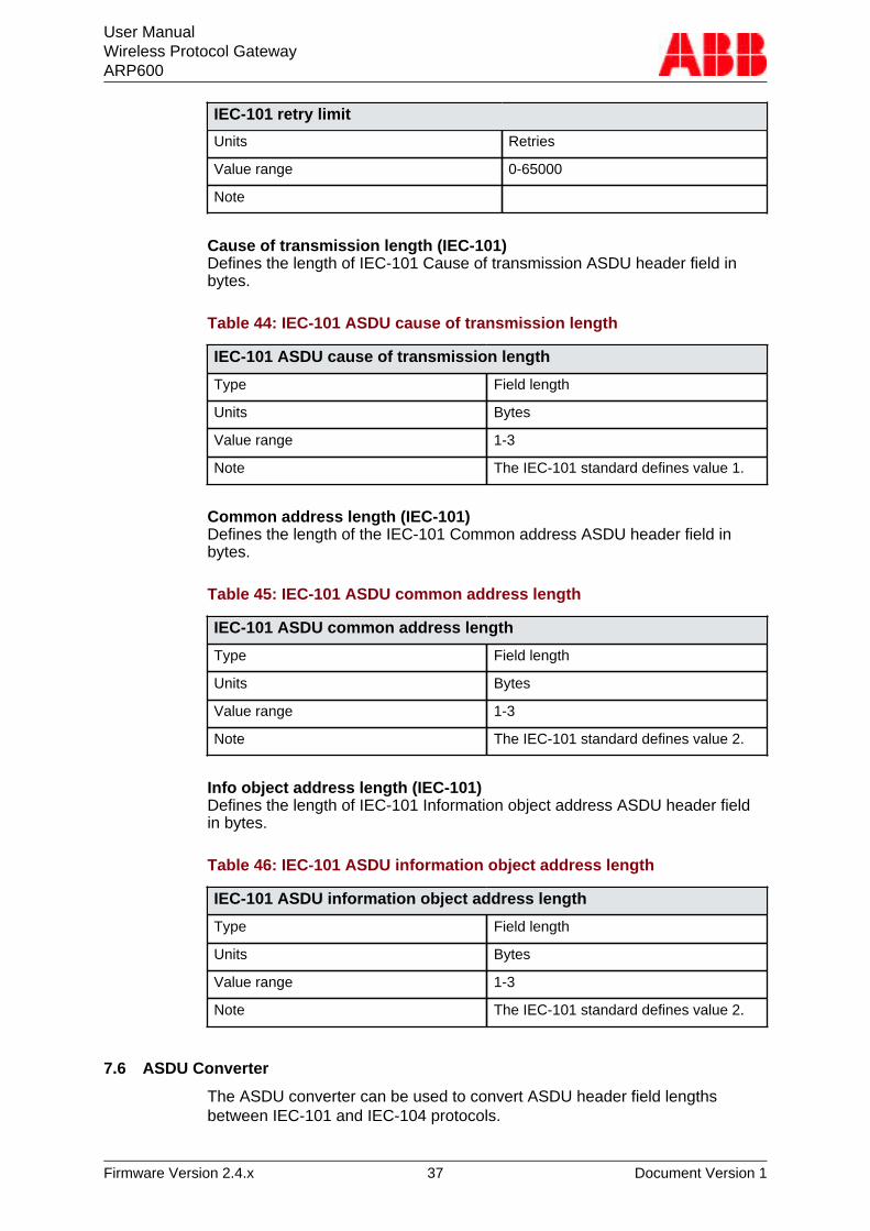
Cause of transmission length (IEC-101)Defines the length of IEC-101 Cause of transmission ASDU header field inbytes.
Table 44: IEC-101 ASDU cause of transmission length
IEC-101 ASDU cause of transmission length
Type Field length
Units Bytes
Value range 1-3
Note The IEC-101 standard defines value 1.
Common address length (IEC-101)Defines the length of the IEC-101 Common address ASDU header field inbytes.
Table 45: IEC-101 ASDU common address length
IEC-101 ASDU common address length
Type Field length
Units Bytes
Value range 1-3
Note The IEC-101 standard defines value 2.
Info object address length (IEC-101)Defines the length of IEC-101 Information object address ASDU header fieldin bytes.
Table 46: IEC-101 ASDU information object address length
IEC-101 ASDU information object address length
Type Field length
Units Bytes
Value range 1-3
Note The IEC-101 standard defines value 2.
7.6 ASDU Converter
The ASDU converter can be used to convert ASDU header field lengthsbetween IEC-101 and IEC-104 protocols.
User ManualWireless Protocol GatewayARP600
Firmware Version 2.4.x 38 Document Version 1
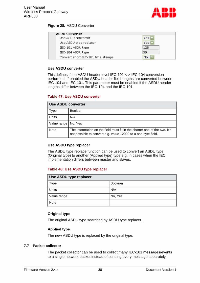
Figure 28. ASDU Converter
Use ASDU converter
This defines if the ASDU header level IEC-101 <-> IEC-104 conversionperformed. If enabled the ASDU header field lengths are converted betweenIEC-104 and IEC-101. This parameter must be enabled if the ASDU headerlengths differ between the IEC-104 and the IEC-101.
Table 47: Use ASDU converter
Use ASDU converter
Type Boolean
Units N/A
Value range No, Yes
Note The information on the field must fit in the shorter one of the two. It’snot possible to convert e.g. value 12000 to a one byte field.
Use ASDU type replacer
The ASDU type replace function can be used to convert an ASDU type(Original type) to another (Applied type) type e.g. in cases when the IECimplementation differs between master and slaves.
Table 48: Use ASDU type replacer
Use ASDU type replacer
Type Boolean
Units N/A
Value range No, Yes
Note
Original type
The original ASDU type searched by ASDU type replacer.
Applied type
The new ASDU type is replaced by the original type.
7.7 Packet collector
The packet collector can be used to collect many IEC-101 messages/eventsto a single network packet instead of sending every message separately.
User ManualWireless Protocol GatewayARP600
Firmware Version 2.4.x 39 Document Version 1
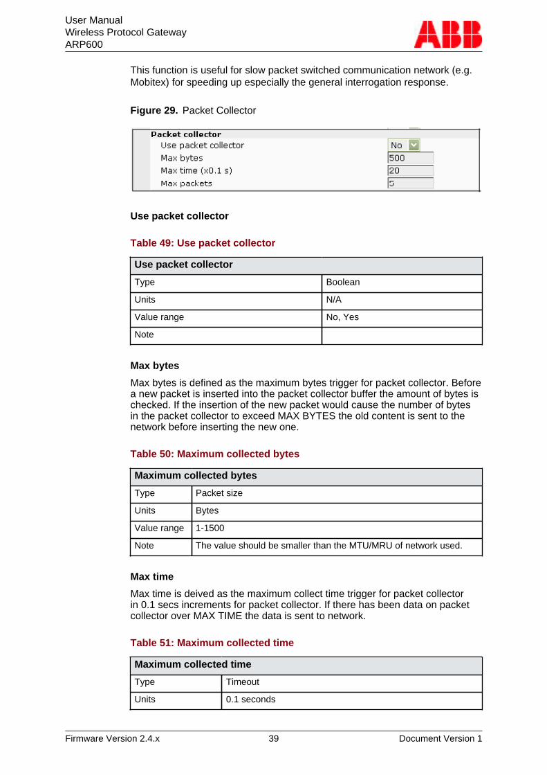
This function is useful for slow packet switched communication network (e.g.Mobitex) for speeding up especially the general interrogation response.
Figure 29. Packet Collector
Use packet collector
Table 49: Use packet collector
Use packet collector
Type Boolean
Units N/A
Value range No, Yes
Note
Max bytes
Max bytes is defined as the maximum bytes trigger for packet collector. Beforea new packet is inserted into the packet collector buffer the amount of bytes ischecked. If the insertion of the new packet would cause the number of bytesin the packet collector to exceed MAX BYTES the old content is sent to thenetwork before inserting the new one.
Table 50: Maximum collected bytes
Maximum collected bytes
Type Packet size
Units Bytes
Value range 1-1500
Note The value should be smaller than the MTU/MRU of network used.
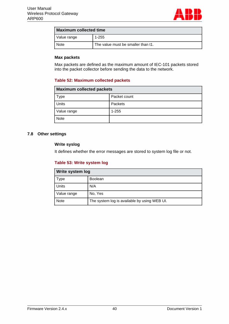
Max time
Max time is deived as the maximum collect time trigger for packet collectorin 0.1 secs increments for packet collector. If there has been data on packetcollector over MAX TIME the data is sent to network.
Table 51: Maximum collected time
Maximum collected time
Type Timeout
Units 0.1 seconds
User ManualWireless Protocol GatewayARP600
Firmware Version 2.4.x 40 Document Version 1
Maximum collected time
Value range 1-255
Note The value must be smaller than t1.
Max packets
Max packets are defined as the maximum amount of IEC-101 packets storedinto the packet collector before sending the data to the network.
Table 52: Maximum collected packets
Maximum collected packets
Type Packet count
Units Packets
Value range 1-255
Note
7.8 Other settings
Write syslog
It defines whether the error messages are stored to system log file or not.
Table 53: Write system log
Write system log
Type Boolean
Units N/A
Value range No, Yes
Note The system log is available by using WEB UI.
User ManualWireless Protocol GatewayARP600
Firmware Version 2.4.x 41 Document Version 1
8 TroubleshootingQ: Wireless WAN is not coming up
A: Check settings (Mobile WAN on page 18), SIM card and signal level. Aneasy way to check the connection status is checking the LEDs, see sectionMobile WAN status LEDs on page 22.
Q: OpenVPN is not working
A: For more information, see OpenVPN application note.
Q: Serial ports are not working
A: For more information, see serial port chapter notes. Verify DIP switchconfiguration if RS-422 or 485 modes are being used.
Q: Can not access web user interface
A: Web user interface uses HTTPS for secure web access and it mustbe specified on the web browser address field like in this example:https://10.10.10.10.
Q: Cannot access the Internet with laptop connected to the device
A: Testing the wireless connection:1. Configure wireless connection and verify if it connected to the network
2. Connect a laptop to Ethernet LAN
3. Check that S-NAT rule on the firewall is set as "Action"="Masquerade" and"Destination Inter- face"="Mobile WAN".
4. Check that DNS Proxy is enabled from Services > Common screen.
5. Configure network settings on laptop to use the device's Ethernet LANaddress as gateway and DNS server.
With these setting, the Internet should be accessible on the laptop.
User ManualWireless Protocol GatewayARP600
Firmware Version 2.4.x 42 Document Version 1
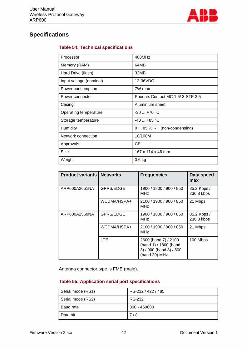
Specifications
Table 54: Technical specifications
Processor 400MHz
Memory (RAM) 64MB
Hard Drive (flash) 32MB
Input voltage (nominal) 12-36VDC
Power consumption 7W max
Power connector Phoenix Contact MC 1,5/ 3-STF-3,5
Casing Aluminium sheet
Operating temperature -30 ... +70 °C
Storage temperature -40 ... +85 °C
Humidity 0 ... 85 % RH (non-condensing)
Network connection 10/100M
Approvals CE
Size 167 x 114 x 46 mm
Weight 0.6 kg
Product variants Networks Frequencies Data speedmax
GPRS/EDGE 1900 / 1800 / 900 / 850MHz
85.2 Kbps /236.8 kbps
ARP600A2651NA
WCDMA/HSPA+ 2100 / 1900 / 900 / 850MHz
21 Mbps
GPRS/EDGE 1900 / 1800 / 900 / 850MHz
85.2 Kbps /236.8 kbps
WCDMA/HSPA+ 2100 / 1900 / 900 / 850MHz
21 Mbps
ARP600A2560NA
LTE 2600 (band 7) / 2100(band 1) / 1800 (band3) / 900 (band 8) / 800(band 20) MHz
100 Mbps
Antenna connector type is FME (male).
Table 55: Application serial port specifications
Serial mode (RS1) RS-232 / 422 / 485
Serial mode (RS2) RS-232
Baud rate 300 - 460800
Data bit 7 / 8

User ManualWireless Protocol GatewayARP600
Firmware Version 2.4.x 43 Document Version 1
Parity None / Even / Odd
Stop bits 1 / 2
Flow control None / Hardware (RTS/CTS)
Techical specifications can be changed without notification.


Contact us
ABB OyMedium Voltage Products,Distribution AutomationP.O. Box 699FI-65101 VAASA, FinlandPhone +358 10 22 11Fax +358 10 22 41094
www.abb.com/mediumvoltage
www.abb.com/substationautomation
1MR
S75
8461
A©
Cop
yrig
ht 2
015
AB
B. A
ll rig
hts
rese
rved
.