Embed Size (px)
Citation preview
Wireless N150 Long Range AP/Router
0

Wireless N150 Long Range AP/Router
1
Copyright Statement
is the registered trademark of Shenzhen IP-COM
Technology Co., Ltd All the products and product names mentioned herein are
the trademarks or registered trademarks of their respective holders.
Copyright of the whole product as integration, including its accessories and
software, belongs to Shenzhen IP-COM Technology Co., Ltd. Without prior
expressed written permission from Shenzhen IP-COM Technology Co., Ltd,
any individual or party is not allowed to copy, plagiarize, reproduce, or
translate it into other languages.
All photos and product specifications mentioned in this manual are for
references only. Upgrades of software and hardware may occur; IP-COM
reserves the right to revise this publication and to make changes in the
content hereof without obligation to notify any person or organization of such
revisions or changes. If you would like to know more about our product
information, please visit our website at www.ip-com.com.cn
Wireless N150 Long Range AP/Router
2
TABLE OF CONTENTS
CHAPTER 1 PRODUCT OVERVIEW .............................................. 5
1.1 FEATURES .................................................................................. 5
1.2 PACKAGE CONTENT ..................................................................... 6
1.3 PANEL OVERVIEW........................................................................ 7
CHAPTER 2 HARDWARE INSTALL .............................................. 10
2.1 HARDWARE INSTALL ................................................................... 10
2.1.1 Connect device to a power source .................................. 10
2.1.2 Network Connection ....................................................... 10
2.2 QUICK SETUP ........................................................................... 13
2.2.1 AP Mode ......................................................................... 14
2.2.2 Router Mode .................................................................. 16
2.2.3 Universal Repeater Mode ............................................... 19
CHAPTER 3 NETWORK SETUP ................................................... 24
3.1 LAN SETTINGS ......................................................................... 24
3.2 WAN SETTINGS ........................................................................ 24
3.3 MAC CLONE ............................................................................ 27
3.4 DHCP .................................................................................... 29
3.5 WAN MEDIUM TYPE ................................................................. 30

Wireless N150 Long Range AP/Router
3
CHAPTER 4 WIRELESS SETTINGS ............................................... 33
4.1 BASIC ..................................................................................... 33
4.2 SECURITY ................................................................................. 35
4.2.1 WPA-PSK ......................................................................... 35
4.2.2 WPA2-PSK ....................................................................... 36
4.2.3 WEP ................................................................................ 36
4.3 WDS ...................................................................................... 37
4.4 OPTIMUM POSITION SETUP ........................................................ 42
4.5 ADVANCED SETTINGS ................................................................. 43
4.6 ACCESS CONTROL ...................................................................... 44
4.7 CONNECTIONSTATUS .................................................................. 46
CHAPTER 5 ADVANCED APPLICATIONS ..................................... 47
5.1 BANDWIDTH SETTINGS ............................................................... 47
5.2 CONNECTION STATUS ................................................................. 48
5.3 DDNS .................................................................................... 48
5.4 VIRTUAL SERVER ....................................................................... 50
5.5 DMZ HOST ............................................................................. 52
5.6 UPNP ..................................................................................... 52
5.7 ROUTING TABLE ........................................................................ 53
5.8 STATIC ROUTING ....................................................................... 54
CHAPTER 6 SECURITY SETTINGS ............................................... 55

Wireless N150 Long Range AP/Router
4
6.1 MAC ADDRESS FILTER ................................................................ 55
6.2 CLIENT FILTER ........................................................................... 56
6.3 URL FILTER .............................................................................. 59
6.4 REMOTE WEB MANAGEMENT ..................................................... 61
CHAPTER 7 SNMP .................................................................... 62
CHAPTER 8 SYSTEM TOOLS ...................................................... 63
8.1 SYSLOG ................................................................................... 63
8.2 STATISTICS ............................................................................... 63
8.3 TIME & DATE ........................................................................... 64
8.4 CHANGE PASSWORD .................................................................. 65
8.5 BACKUP .................................................................................. 66
8.6 RESTORE ................................................................................. 66
8.7 FIRMWARE UPDATE ................................................................... 67
8.8 RESTORE TO FACTORY DEFAULT .................................................... 68
8.9 REBOOT .................................................................................. 68
APPENDIX 1 TCP/IP SETTINGS .................................................. 70
APPENDIX 2 GLOSSARY ............................................................ 77
APPENDIX 3 FAQS .................................................................... 79
APPENDIX 4 SAFETY AND EMISSION STATEMENT ...................... 82
Wireless N150 Long Range AP/Router
5
Chapter 1 Product Overview
Thanks for purchasing this P115AP Wireless N150 Outdoor Long Range
AP/Router.
The IP-COM P115AP is an outdoor long range wireless AP/router with wireless
speed up to 150M. Combining the function of a wireless router, wireless AP,
WISP, Client+AP and WDS, etc. the device nicely stands out in outdoor long
range wireless connections, P2P, P2MP networking, wireless monitoring
applications and much more.The P115AP is housed in an IP64
water/dust-proof enclosure. Also, it is lightning proof and power tunable. In
addition to internal antenna design, it comes with an optional external
antenna connector for DIY or upgrade. Plus, it is PoE capable and can be reset
remotely.
1.1 Features
Compliant with IEEE802.11n and backward compatible with
IEEE802.11g/b
Up to 150Mbps over 2.4G
5 operating modes: Wireless Router, Wireless AP, Wireless WAN (WISP),
Universal Repeater (Client+AP) and Bridge
Internal 10dBi directional antenna; plus optional external RP-SMA
antenna connector for DIY or upgrade (To use an external antenna,
you must first shift antenna type from internal to external on wireless
module)
Power tunable at 3 levels: high, medium and low
Able to be powered by a passive PoE injector; flexibly deploy your AP at
ease
6000V lightning proof design (bidirectional);
Provides encryption methods of 64-/128-bit WEP, WPA-PSK and
WPA2-PSK, etc to secure your wireless network
Provides 1 WAN/LAN/PoE interchangeable port and 1 separate LAN port
Wireless Roaming technology to ensure high-efficiency wireless

Wireless N150 Long Range AP/Router
6
connectivity
Access Control based on MAC address
Provides logs to record device's usage status
Watchdog helps to recover system upon network failure
Able to reset AP using the Reset button on the PoE injector
Allow/disallow specified PCs on LAN to access Internet while operating
in Router Mode
Support virtual server and DMZ host when operating in Router Mode
Support internal firewall to block attacks from hackers when operating
in Router Mode
1.2 Package Content
Unpack the box and verify the following items:
P115AP x 1
Screw x 2
Nylon Ligature x 2
Plastic Bag x 2
Ethernet Cable x 1
Power Adapter x 1
Injector x 1
Installation Guide x 1
CD x 1
If any of the above items are incorrect, missing, or damaged, please contact
your local reseller for immediate replacement.
Wireless N150 Long Range AP/Router
7
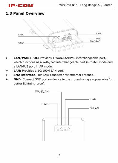
1.3 Panel Overview
LAN/WAN/POE: Provides 1 WAN/LAN/PoE interchangeable port,
which functions as a WAN/PoE interchangeable port in router mode and
a LAN/PoE port in AP mode.
LAN: Provides 1 10/100M LAN port.
SMA interface:RP-SMA connector for external antenna.
GND: Connect GND port on device to the ground using a copper wire for
better lightning-proof.

Wireless N150 Long Range AP/Router
8
LEDs are described as below:
LED Status Description
PWR A solid blue light Device has electrical
power
WAN/LAN
A solid blue light Ethernet cable is
connected
A blinking blue light Transferring data
LAN
A solid blue light Ethernet cable is
connected
A blinking blue light Transferring data
WLAN
Blue
Transmitting wireless
signal at a high power
level
Pink
Transmitting wireless
signal at a medium power
level
Red
Transmitting wireless
signal at a low power
level

Wireless N150 Long Range AP/Router
9
Injector Overview
POE: Power over Ethernet port.
LAN/WAN: 100M Ethernet port.
Reset: Pressing it for 8-10s restores device to factory default settings.
Power: Power connector.

Wireless N150 Long Range AP/Router
10
Chapter 2 Hardware Install
2.1 Hardware Install
Before you start configuring the device, follow below steps to install device.
For extended wireless coverage, use an external omni-directional antenna
and place device in the center of the area for better performance; to
implement long range P2P or P2MP wireless bridge, use the internal
directional antenna and position device properly for better performance.
2.1.1 Connect device to a power source
The device comes with a PoE injector. Please use it to power the device.
2.1.2 Network Connection
Wireless N150 Long Range AP/Router
11
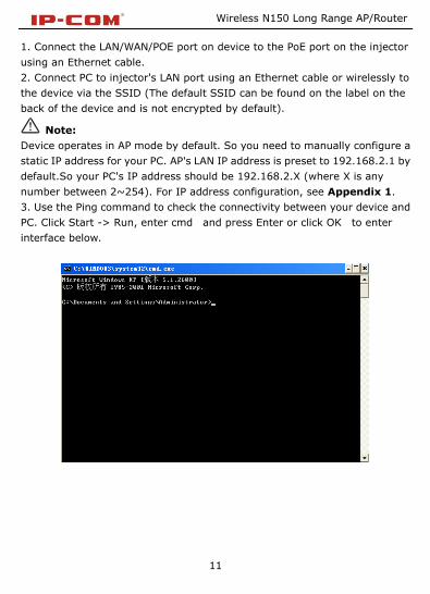
1. Connect the LAN/WAN/POE port on device to the PoE port on the injector
using an Ethernet cable.
2. Connect PC to injector's LAN port using an Ethernet cable or wirelessly to
the device via the SSID (The default SSID can be found on the label on the
back of the device and is not encrypted by default).
Note:
Device operates in AP mode by default. So you need to manually configure a
static IP address for your PC. AP's LAN IP address is preset to 192.168.2.1 by
default.So your PC's IP address should be 192.168.2.X (where X is any
number between 2~254). For IP address configuration, see Appendix 1.
3. Use the Ping command to check the connectivity between your device and
PC. Click Start -> Run, enter cmd and press Enter or click OK to enter
interface below.

Wireless N150 Long Range AP/Router
12
4. Input ping 192.168.2.1 and press Enter.
If you get a screen as shown in the screenshot above, your PC and device are
interconnected.
If you get a screen as shown in the screenshot above, your PC and device are
not interconnected. Please follow below steps to troubleshoot the problem.
1) Verify Ethernet cable connection
The LAN LED on the device and PC's adapter LED should be on.

Wireless N150 Long Range AP/Router
13
2) Verify TCP/IP settings on your PC
To access device web utility while operating in AP mode or universal repeater
mode, manually configure a static IP address for the PC. Just note that the IP
address you configure must be on the same net segment as device LAN IP
address. While in router mode, you can either manually specify an IP address
for the PC or set it to Obtain an IP address automatically.
2.2 Quick Setup
The device is configurable and manageable through a web browser. Launch a
web browser, in the address bar, input 192.168.2.1 and press Enter. Enter
admin in both User Name and Password fields (Both default user name
and password are admin).
Click Login on the login window, and then click Quick Setup. Select a proper
mode for device to operate on from AP Mode, Router Mode and Universal
Repeater Mode.

Wireless N150 Long Range AP/Router
14
Operating Mode Overview:
AP Mode: In this mode, the device converts the wired signal into
wireless signals, extending existing network coverage. It works as a
central access point for multiple wireless clients (generally, wireless
adapters) concurrently.
Router Mode: Operating in this mode, device functions as a regular
wireless router. It supports PPPoE, dynamic IP (DHCP) , PPTP, L2TP and
static IP Internet connection types and provide DHCP server feature
that dynamically assigns IP addresses to DHCP-client-capable PCs for
Internet connection sharing. Wireless WAN (WISP) and WDS features
are available in this mode.
Universal Repeater Mode(Client+AP): Device wirelessly bridges an
uplink device to repeat wireless and extend coverage.
2.2.1 AP Mode
See below for the typical network topology. Position device properly according
to practical network environment.

Wireless N150 Long Range AP/Router
15
1. Connect the LAN/WAN/POE port on device to the POE port on the
injector.
2. Connect the LAN port on the PoE injector to an uplink switch or
router.
3. All PCs in the range will then be able to connect to this SSID
wirelessly for Internet access.
Device operates in AP mode by default, so simply follow the topology above to
establish th network. To configure other features like wireless, simply access
the device web management utility. For details, see Chapter 4

Wireless N150 Long Range AP/Router
16
2.2.2 Router Mode
Typical Topology:
1. Connect the LAN/WAN/POE port on device to the POE port on the
injector.
2. Connect the LAN port on PoE injector to ISP.
3. All PCs in the range will then be able to connect to this SSID
wirelessly for Internet access.
1. Select Router Mode, click Next and then configure basic wireless
settings including SSID, channel and security.

Wireless N150 Long Range AP/Router
17
SSID: A SSID (Service Set Identifier) is the public name of a wireless
network.
Channel: For an optimal wireless performance, you may select the
least interferential channel. It is advisable that you select an unused
channel or Auto to let device detect and select the best possible
channel for your wireless network to operate on from the drop-down list.
The default is Auto.
Security Mode (Encryption Algorithm): Select a proper
encryption algorithm: WEP, WPA-PSK or WPA/WPA2-PSK. For
more information, see Chapter 4.
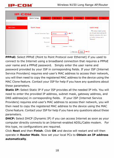
2. Click Next and select a proper Internet connection type, say, PPPoE,
Static IP or DHCP.
Wireless N150 Long Range AP/Router
18
PPPoE: Select PPPoE (Point to Point Protocol over Ethernet) if you used to
connect to the Internet using a broadband connection that requires a PPPoE
user name and a PPPoE password. Simply enter the user name and
password provided by your ISP in corresponding fields. If your ISP (Internet
Service Providers) requires end-user's MAC address to access their network,
you will then need to copy the registered MAC address to the device using the
MAC Clone feature. Contact your ISP for help if you have any questions about
these parameters.
Static IP: Select Static IP if your ISP provides all the needed IP info. You will
need to enter the provided IP address, subnet mask, gateway address, and
DNS address(es) in corresponding fields. If your ISP (Internet Service
Providers) requires end-user's MAC address to access their network, you will
then need to copy the registered MAC address to the device using the MAC
Clone feature. Contact your ISP for help if you have any questions about these
parameters.
DHCP: Select DHCP (Dynamic IP) if you can access Internet as soon as your
computer directly connects to an Internet-enabled ADSL/Cable modem. For
this type, no configurations are required.
Click Next and then Finish. Click OK and device will restart and will then
operate in Router Mode. Now set your local PCs to Obtain an IP address
automatically.

Wireless N150 Long Range AP/Router
19
2.2.3 Universal Repeater Mode
Typical Topology:
AP1 that operates in Router Mode has connected to Internet. AP2 connects
to AP1 using the Universal Repeater Mode. So, clients that connect to AP2
can also access Internet.
1. Select Universal Repeater Mode on Quick Setup screen and then click
Next.
2. Click Scan and all wireless networks in the area will be displayed. Select
the SSID (the name of a wireless network) you wish to connect, say,
IP-COM_2, and then click Next.

Wireless N150 Long Range AP/Router
20
SSID, MAC address and channel fields will be populated automatically.
3. What you need to do is to configure the security settings. For example, the
Security Mode, Security Key and Key Update Interval for the SSID
IP-COM_2is WPA-PSK, 12345678 and 3600s, simply enter them.

Wireless N150 Long Range AP/Router
21
4. Click Next and configure wireless settings for the device. Device MUST
operate on the same channel as the uplink AP for successful implementation
of the feature. The channel field on device greyed out in this mode. SSID and
security settings are configurable (both can be different from the uplink
device).

Wireless N150 Long Range AP/Router
22
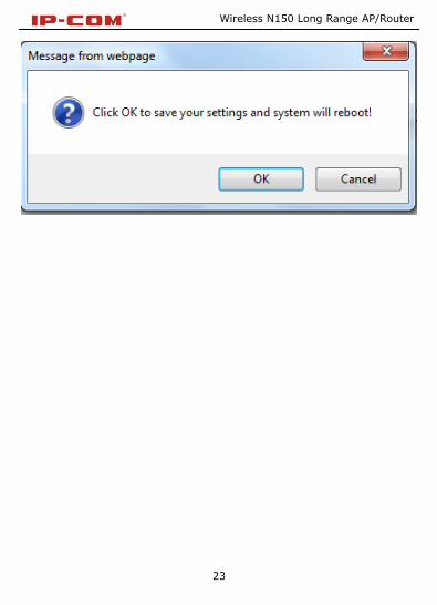
5. Click Next and then Finish. Click OK and device will restart and will then
operate in Universal Repeater Mode.
Now set your local PCs to Obtain an IP address automatically and these
PCs will then use IP/gateway/DNS addresses assigned by the uplink device to
access Internet.
Wireless N150 Long Range AP/Router
23

Wireless N150 Long Range AP/Router
24
Chapter 3 Network Setup
This chapter mainly explains LAN settings in AP Mode, Universal Repeater
Mode and Router Mode, as well as WAN settings, MAC Clone, DHCP server and
WAN Medium Type (Wired or Wireless WAN).
3.1 LAN Settings
IP Address: Device's LAN IP address, 192.168.2.1 by default. You can
change it according to your needs; just remember to use the new one to
log on to the device’s web utility if you changed it.
Subnet Mask: Device’s LAN subnet mask, 255.255.255.0 by default.
Note: If you change the device’s LAN IP address, you must use the new
one to log on to the web-based configuration utility. To synchronize
system time in AP Mode and Universal Repeater Mode, make sure your
device's LAN IP address is on the same net segment as the uplink device,
and set gateway and DNS addresses the same as uplink device's IP
address.
3.2 WAN Settings
WAN settings are only available in Router Mode.

Wireless N150 Long Range AP/Router
25
PPPoE
Internet connection Type: Displays the current Internet connection
type.
User Name: Enter the User Name provided by your ISP.
Password: Enter the password provided by your ISP.
MPPE: Microsoft Point-to-Point Encryption (MPPE) is a protocol for
encrypting data across Point-to-Point Protocol (PPP) and virtual private
network (VPN) links.By default it is disabled. However if ISP enables
MPPE on his PPPoE server, you must also enable it on the device. Consult
your ISP, if you don't know whether he has enabled the MPPE or not.
MTU: Maximum Transmission Unit. DO NOT change it from the factory
default of 1492 unless necessary. You may need to change it for optimal
performance with some specific websites or application software that
cannot be opened or enabled; in this case, try 1450, 1400, etc.

Wireless N150 Long Range AP/Router
26
Static IP
If your ISP assigns a fixed IP address to you, then select Static IP, and enter
the IP address, subnet mask, primary DNS and secondary DNS (optional) info
provided by your ISP in corresponding fields.
IP Address: Enter the WAN IP address provided by your ISP. Consult your
ISP if you are not clear.
Subnet Mask: Enter WAN Subnet Mask provided by your ISP. The
default is 255.255.255.0.
Gateway: Enter the WAN Gateway provided by your ISP. Consult your
ISP if you are not clear.
Primary DNS Server: Enter the DNS address provided by your ISP.
Secondary DNS Server: Enter the other DNS address if your ISP
provides 2 such addresses (optional).
MTU: Maximum Transmission Unit. DO NOT change it from the factory
default of 1500 unless necessary. You may need to change it for optimal
performance with some specific websites or application software that
cannot be opened or enabled; in this case, try 1450, 1400, etc.

Wireless N150 Long Range AP/Router
27
DHCP (Dynamic IP)
Select DHCP (Dynamic IP) if you can access Internet as soon as your
computer directly connects to an Internet-enabled ADSL/Cable modem.
Device will automatically obtain an IP address from ISP.
3.3 MAC Clone
This section allows you to configure Device’s WAN MAC address. This feature
is only available in Router Mode.
Normally you don't need to change device's default WAN MAC address.

Wireless N150 Long Range AP/Router
28
However, some ISPs may bind client PC's MAC address for Internet connection
authentication. In this case, simply enter the bound MAC in the WAN MAC
Address field or click "Copy My PC's MAC" (or Clone MAC) to copy your PC's
MAC to the device.
MAC Address: Config device’s WAN MAC address and click Save to
save your settings.
Clone MAC: Click to automatically copy your local PC's MAC address to
the device as device's new WAN MAC address.
Restore to Factory Default MAC: Reset Device’s WAN MAC to factory
default.

Wireless N150 Long Range AP/Router
29
3.4 DHCP
The Dynamic Host Configuration Protocol (DHCP) is an automatic
configuration protocol used on IP networks. If you enable the built-in DHCP
server on this device, it will automatically configure TCP/IP protocol settings
for all DHCP-Client-enabled PCs in your LAN (Namely, PCs are set to "Obtain
an IP address automatically" and "Obtain DNS server address automatically"),
including IP address, subnet mask, gateway and DNS etc, eliminating the
need for manual intervention.
DHCP Server: enable or disable the device’s DHCP server feature. If
enabled, the DHCP server will assign IP addresses to requesting clients.
Start IP Address: Specify the starting IP address for the DHCP server
IP assignment.
End IP Address: Specify the ending IP address for the DHCP server IP
assignment.
Primary DNS Server: Specify a primary DNS address for requesting
clients.
Secondary DNS Server: Specify a secondary DNS address for

Wireless N150 Long Range AP/Router
30
requesting clients. This field is optional.
Lease Time: The length of time for the IP address lease. Configuring a
proper lease time improves the efficiency for the DHCP server to reclaim
disused IP addresses.
For example: If the lease time is set to one hour, then the DHCP server
will reclaim disused IP addresses every hour.
3.5 WAN Medium Type
Here you can select a proper WAN medium type to use: Wireless WAN (WISP)
or Wired WAN to connect to the uplink device. Internet connection types are
the same for the two medium types.
Wired WAN: Connect to uplink device via an Ethernet cable.
Wireless WAN: Connect to uplink device (WISP AP) wirelessly.
Please do following the steps as below if you connect to the Internet
wirelessly.
1. Select Wireless WAN (WISP) and click Scan. Currently available
wireless networks will then be displayed.
2. Select the SSID you wish to connect and SSID, MAC address and

Wireless N150 Long Range AP/Router
31
channel fields will then be automatically populated. For example, the
security mode (encryption algorithm) and security key for the SSID
IP-COM_2 is WPA-PSK, and 12345678 3600s, simply enter them and
click Save.
Figure 1

Wireless N150 Long Range AP/Router
32
Figure 2
3. Click OK and device will restart and will then operate in Wireless WAN
(also known as WISP Mode).
Note:
When operating in Wireless WAN (WISP Mode), make sure device is
operating on the same channel as the uplink device (WISP AP). While SSID
and security settings on device are not required so.

Wireless N150 Long Range AP/Router
33
Chapter 4 Wireless Settings
This chapter mainly presents wireless settings, including basic wireless
settings, security, WDS, access control settings and connection status.
4.1 Basic
Wireless: Check to enable the wireless feature.
Antenna: Select to use internal antenna or external antenna.
SSID: This is the public name of your wireless network. This field does
not allow Chinese characters and special characters: ; \ ~ ,;“ & %, etc.
SSID Broadcast: Select “Enable”/“Disable” to make your wireless
network visible/ invisible to any wireless clients within coverage when
they perform a scan to see what’s available. When disabled, this SSID becomes
invisible to any wireless clients within the coverage. Manually enter the SSID if you want
to connect to it.
802.11 Mode: Select a wireless network mode.
11b mode: Select it if you have only Wireless-B clients in your wireless

Wireless N150 Long Range AP/Router
34
network.
11g mode: Select it if you have only Wireless-G clients in your wireless
network.
11b/g mixed mode: Select it if you have only Wireless-B and Wireless-G clients in your
wireless network.
11b/g/n mixed mode: Select it if you have Wireless-b/g/n clients in your wireless
network.
Channel: For an optimal wireless performance, you may select the least
interferential channel. It is advisable that you select an unused channel
or Auto to let device detect and select the best possible channel for your
wireless network to operate on from the drop-down list.
Channel Bandwidth: Select a proper channel bandwidth to enhance
wireless performance. When there are 11b/g and 11n wireless clients,
please select the 802.11n mode of 40M frequency band; when there are
only non-11n wireless clients, select 20M frequency band mode; when
the wireless network mode is 11n mode, please select 20/40 frequency
band to boost its throughput.
TX Power: Select a proper transmission power level for device (Low
power: 100mW, medium power: 200mW, high power: 300mW). The
default TX power level is High.
Extension Channel: It is used to ensure N speed for 802.11n devices on
the network.
WMM-Capable: WMM is QoS for your wireless network. Enabling this
option may better stream wireless multimedia data (such as video or
audio).
ASPD Capable: Select to enable/disable the auto power saving mode.
Wireless N150 Long Range AP/Router
35
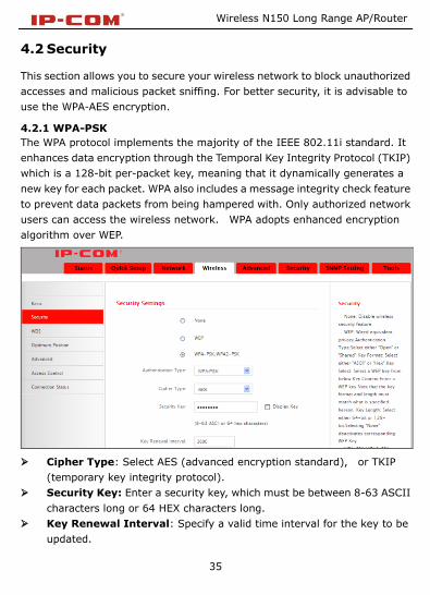
4.2 Security
This section allows you to secure your wireless network to block unauthorized
accesses and malicious packet sniffing. For better security, it is advisable to
use the WPA-AES encryption.
4.2.1 WPA-PSK
The WPA protocol implements the majority of the IEEE 802.11i standard. It
enhances data encryption through the Temporal Key Integrity Protocol (TKIP)
which is a 128-bit per-packet key, meaning that it dynamically generates a
new key for each packet. WPA also includes a message integrity check feature
to prevent data packets from being hampered with. Only authorized network
users can access the wireless network. WPA adopts enhanced encryption
algorithm over WEP.
Cipher Type: Select AES (advanced encryption standard), or TKIP
(temporary key integrity protocol).
Security Key: Enter a security key, which must be between 8-63 ASCII
characters long or 64 HEX characters long.
Key Renewal Interval: Specify a valid time interval for the key to be
updated.

Wireless N150 Long Range AP/Router
36
4.2.2 WPA2-PSK
The later WPA2 protocol features compliance with the full IEEE 802.11i
standard and uses Advanced Encryption Standard (AES) in addition to TKIP
encryption protocol to guarantee better security than that provided by WEP or
WPA.
Cipher Type: Select AES (advanced encryption standard) or TKIP
(temporary key integrity protocol) &AES.
Security Key: Enter a security key, which must be between 8-63 ASCII
characters long or 64 HEX characters long.
Key Renewal (Update) Interval: Specify a valid time interval for the
key to be updated.
4.2.3 WEP
WEP is intended to provide data confidentiality comparable to that of a
traditional wired network.

Wireless N150 Long Range AP/Router
37
Authentication Type: Select a proper authentication type.
WEP Key Format: Select a proper key format: HEX or ASCII.
Key Select: Select a key from the preset keys 1-4 for current use.
4.3 WDS
WDS Bridge Mode: wireless distribution system (WDS) is a system enabling
the wireless interconnection of access points in an IEEE 802.11 network. It
allows a wireless network to be expanded using multiple access points without
the traditional requirement for a wired backbone to link them.Note: The
Access Points you select MUST support WDS. Select Wireless AP from WDS
Mode and Enable from WDS Status to enter screen below:

Wireless N150 Long Range AP/Router
38
WDS Mode: Select Repeater or Bridge. When operating in Bridge mode,
other wireless clients (excluding bridge participants) will not be able to
connect to the device; when operating in Repeater mode, other wireless
clients will still be able to connect to the device via SSID.
WDS Status: Select Enable or Disable.
Scan: Click to scan wireless networks (SSIDs and BSSID) in the area
after you enable the WDS feature.
Remote Bridge's MAC Address: Enter the MAC address of the wireless
device you want to connect (link partner).

Wireless N150 Long Range AP/Router
39
Take two P115APs as an example to illustrate WDS implementation.
Select Repeater from WDS Mode and Enable from WDS Status.
1 Directly enter the MAC address of the link partner if you already know it and
then click OK.
2 Enable scan on one associated device to search for the link partner.
1) Click Scan.

Wireless N150 Long Range AP/Router
40
2) Select the SSID you wish to connect, click Save and its MAC address will
then be added automatically to device.

Wireless N150 Long Range AP/Router
41
Click Save to save your settings. And then configure same settings on the
bridge partner device. When up appears, you have successfully connected to
it.
Note:
WDS feature can only be implemented between 2 WDS-capable wireless
devices. Plus, SSID, channel, security settings and security key must be
exactly the same on both such devices.
To authenticate on wireless client access, go to Wireless -> Security. After
you finish the configurations, remember to reboot the device for proper WDS
communication.
3. Each device can bridge up to 4 wireless devices.
Wireless N150 Long Range AP/Router
42
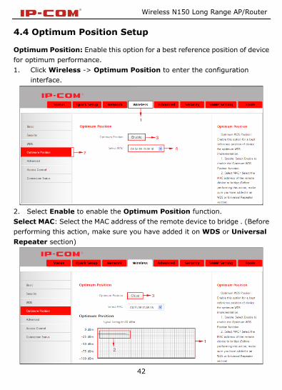
4.4 Optimum Position Setup
Optimum Position: Enable this option for a best reference position of device
for optimum performance.
1. Click Wireless -> Optimum Position to enter the configuration
interface.
2. Select Enable to enable the Optimum Position function.
Select MAC: Select the MAC address of the remote device to bridge . (Before
performing this action, make sure you have added it on WDS or Universal
Repeater section)

Wireless N150 Long Range AP/Router
43
Place and hold the device in different places for a certain period of time (5
seconds is recommended), observe signal strength change from the graph.
Position device exactly where as it is when strongest signal appears on the
graph.
Note:
1. The smallest signal strength absolute value on vertical axis indicates best
signal strength.
2. When you have positioned the device ideally for bridge, remember to
disable the Optimum WDS Position function. So it may not affect your
wireless performance.
4.5 Advanced Settings
This section allows you to configure advanced settings, including AP Isolation,
Beacon interval,Fragment threshold,RTS threshold and DTIM interval, etc,
for your wireless networks.
AP Isolation: Isolates clients connecting to master SSID.
Beacon Interval: A time interval between any 2 consecutive Beacon
packets sent by an Access Point to synchronize a wireless network. Do
NOT change the default value of 100 unless necessary.
Fragment Threshold: Specify a Fragment Threshold value. Any
wireless packet exceeding the preset value will be divided into several

Wireless N150 Long Range AP/Router
44
fragments before transmission. DO NOT change the default value of
2346 unless necessary.
RTS Threshold: If a packet exceeds such set value, RTS/CTS scheme
will be used to reduce collisions. Set it to a smaller value provided that
there are distant clients and interference. For normal SOHO, it is
recommended to keep the default value unchanged; otherwise, device
performance may be degraded.
DTIM Interval: A DTIM (Delivery Traffic Indication Message) Interval is
a countdown informing clients of the next window for listening to
broadcast and multicast messages. When such packets arrive at device’s
buffer, the device will send DTIM (delivery traffic indication message)
and DTIM interval to wake clients up for receiving these packets.
4.6 Access Control
The MAC-based Wireless Access Control feature can be used to allow or
disallow clients to connect to your wireless network.
Access Control: Disabled by default. Click Enable to enable the feature.
Deny Access to Wireless Network: Block only PCs at specified MAC
addresses from connecting to your wireless network.
Allow Access to Wireless Network: Allow only PCs at specified MAC
addresses to connect to your wireless network.

Wireless N150 Long Range AP/Router
45
Click Add and below screen appears:
MAC Address: Enter the MAC address of a wireless client.
Description: Briefly describe the current entry/rule.
Status: Select Enable or Disable.
Up to 6 rules can be added.
Example: To allow only the PC at the MAC address of 00:90:4C:85:11:05 to
connect to your wireless network, do as follows:
1. Click Add, enter 00:90:4C:85:11:05 in the MAC Address field, select
Enable and then click Save as seen in the screenshot below.

Wireless N150 Long Range AP/Router
46
2. You will be redirected to the initial page of this feature. The rule you just
added will be displayed there. Select Allow Access to Wireless Network
and Enable as seen in the screenshot below:
4.7 ConnectionStatus
This section displays the info of connected wireless clients including MAC
addresses and encryption info, etc.

Wireless N150 Long Range AP/Router
47
Chapter 5 Advanced Applications
The Advanced tab only works on router mode, it has the following 7
submenus: Bandwidth Settings, Connection Status, DDNS, Virtual Server,
DMZ Host, UPnP, Routing Table and Static Routing.
5.1 Bandwidth Settings
Bandwidth control is used for limit internal network speed. It supports IP
address range configuration. Click Add and below screen will appear.
Enable: Check/uncheck to enable/disable current entry.
When disabled, corresponding entry will not take effect though existing
in fact.
IP Range: Enter a single IP or an IP range.
Uplink Bandwidth: Max uplink traffic.
Downlink Bandwidth: Max downlink traffic.
Description: Briefly describe the current rule, the Max number of rule is
10.

Wireless N150 Long Range AP/Router
48
5.2 Connection status
Showing the current connection information, which is client IP address, MAC
address and connection mode.
5.3 DDNS
Dynamic DNS or DDNS is a method of updating, in real time, a Domain Name
System (DNS) to point to a changing IP address on the Internet. This is used
to provide a persistent domain name for a resource that may change location
on the network.

Wireless N150 Long Range AP/Router
49
1、Mostly, broadband ISP (Internet service provider) only provide client with
Dynamic IP address. While DDNS knows every change on IP address and
Banding it with well-known name, so others users can use well-known name
to communicate with the client.
2、DDNS can help you setup virtual server in your company or home.
Service Provider: Select the DDNS service provider you are using,
support no-ip, dyndns.
User Name: Enter the DDNS user name registered with your DDNS
service provider.
Password: Enter the DDNS Password registered with your DDNS service
provider.
Domain Name: Enter the DDNS domain name with your DDNS service
provider.
For example: If you have registered a DDNS service from no-ip.com for a web
server on the host at 192.168.2.10 and get below info:
User Name IP-COM
Password 123456
Domain Name ip-com.zapto.org
First set a mapping rule on Virtual Server interface (For details, see Virtual
Server section) and then enter the registered user name, password and
domain name as shown below:

Wireless N150 Long Range AP/Router
50
Then Click Save to save the settings.
Simply input "http://ip-com.zapto.org" in a launched web browser and your
web server will be accessible.
5.4 Virtual Server
Defines the mapping between the service port range of WAN access and LAN
server, all of the WAN ports used within the scope of access will be
re-positioned to the LAN network server specified by IP address.

Wireless N150 Long Range AP/Router
51
Ext Port-Int Port: WAN service port. Internal LAN PC port
corresponding mapped to an external port.
Private IP: The IP address of a computer used as a server in LAN.
Protocol: Includes TCP, UDP and Both. Select “Both” if you are not sure
about which protocol to use.
Enable: The corresponding entry takes effect only if you.
checked this option.
Delete: Clear all settings of this item.
Common Service Port: The well-known protocol ports are listed in the
drop-down list. Select one and select a sequence number in the ID
drop-down list and then click “Add”, this port will be added automatically
to the ID list. For other well-known service ports that are not listed, you
can manually add them to the list.
Add to: Add the selected well-known port to the policy ID.
For Example: you can build a WEB server on your computer and set the
router’s port range forwarding to enable your friends to access to your
computer. Suppose that your WEB server or your computer’s static IP address
is 192.168.2.100, and you wish your friends can access the server through
the default port 80 and adopts TCP protocol.

Wireless N150 Long Range AP/Router
52
Notice: If you set the service port of the virtual server as 80, you must set the
Web Management port on Remote Web Management screen to be any value
except 80 such as 8080. Otherwise, there will be a conflict to disable the
virtual server.
5.5 DMZ Host
The DMZ Settings screen allows one local computer to be exposed to the
Internet for use of a special-purpose service such as Internet gaming or
videoconferencing. DMZ hosting forwards all the ports at the same time to
one PC.
DMZ Host IP: The IP address of the LAN computer you want to set as
DMZ host.
Enable: Check to enable the DMZ host.
For example:
Set the computer at the IP address of 192.168.2.10 as DMZ host to connect
another host on the Internet for intercommunication.
Notice: When the DMZ host is enabled, the firewall settings of the DMZ host
will not function.
5.6 UPnP
With the UPnP (Universal Plug and Play) function, the internal host can

Wireless N150 Long Range AP/Router
53
request the router to process some special port switching so as to enable the
external host to visit the resources of the internal host.
UPnP works in Windows XP, Windows ME or later (Note: Operational system
needs to be integrated with or installed with DirectX 9.0) or in an environment
with installed application software that supports UPnP.
Enable UPnP: Click the checkbox to enable the UPnP.
5.7 Routing Table
This page shows the router’s core routing table.
Wireless N150 Long Range AP/Router
54
The main duty for a router is to look for a best path for every data packet, and
transfer this data packet to a destination station. In order to fulfill this
function, many transferring paths, i.e. routing table, are saved in the router,
for choosing when needed.
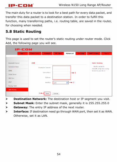
5.8 Static Routing
This page is used to set the router’s static routing under router mode. Click
Add, the following page you will see.
Destination Network: The destination host or IP segment you visit.
Subnet Mask: Enter the subnet mask, generally it is 255.255.255.0
Getaway: The entry IP address of the next router.
Interface: If destination need go through WAN port, then set it as WAN.
Otherwise, set it as LAN.
Wireless N150 Long Range AP/Router
55
Chapter 6 Security Settings
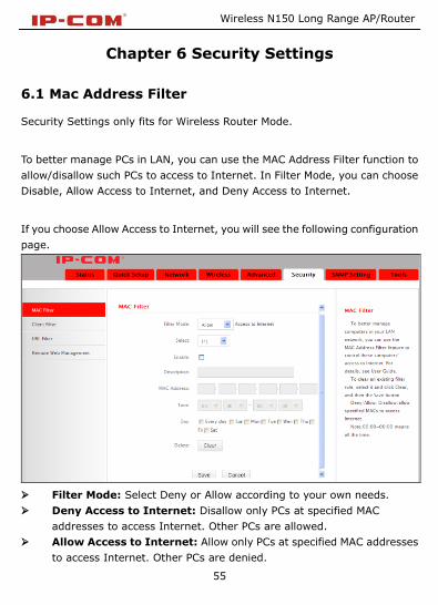
6.1 Mac Address Filter
Security Settings only fits for Wireless Router Mode.
To better manage PCs in LAN, you can use the MAC Address Filter function to
allow/disallow such PCs to access to Internet. In Filter Mode, you can choose
Disable, Allow Access to Internet, and Deny Access to Internet.
If you choose Allow Access to Internet, you will see the following configuration
page.
Filter Mode: Select Deny or Allow according to your own needs.
Deny Access to Internet: Disallow only PCs at specified MAC
addresses to access Internet. Other PCs are allowed.
Allow Access to Internet: Allow only PCs at specified MAC addresses
to access Internet. Other PCs are denied.

Wireless N150 Long Range AP/Router
56
Select: Select a number (indicating a corresponding entry) from the
drop-down menu. Up to 10 rules can be set.
Enable: Check/uncheck to enable/disable the corresponding entry.
Description: Enter a meaningful name to you for corresponding entry.
MAC Address: Enter the PC’s MAC address that you want to filter out.
Time: Select a time range for the corresponding entry to take effect, or
else the default time is 00:00~00:00, which means the entry will be
effective all the day.
Day: select a day or several days for the corresponding entry to take
effect.
Example:To allow a PC at the MAC address of 00:00:4C:77:88:99 to
access Internet from 00:00 to18:00 everyday, configure same settings
on the screenshot below on your device:
Click Save to save the settings.
6.2 Client Filter
To better manage PCs in LAN, you can allow or disallow such PCs to access

Wireless N150 Long Range AP/Router
57
certain ports on Internet using the Client Filter functionality.
Filter Mode: Select Deny or Allow according to your own needs.
Disable: disable the corresponding entry.
Deny Access to Internet: Disallow PCs at specified IP addresses to
access certain ports on Internet.
Allow Access to Internet: Allow only PCs at specified IP addresses to
access certain ports on Internet.
Select: Select a number (indicating a filter rule) from the drop-down
menu. Up to 10 rules can be set.
Enable: Check/uncheck to enable/disable the corresponding entry.
Description: Enter a meaningful name to yourself for a new filter rule.
Start IP: Enter a starting IP address.
End IP: Enter an ending IP address.
Port: Enter TCP/UDP protocol port number (s); it can be a range of
ports or a single port from 1 to 65534.
Traffic Type: Select a protocol or protocols for the traffic
(TCP/UDP/Both).
Time: Select a time range for the rule to take effect.

Wireless N150 Long Range AP/Router
58
Day: Select a day or several days for the rule to take effect.
Example: To forbid PCs within the IP address range of
192.168.2.20--192.168.2.30 to visit websites from 9:00 to
18:00, do as follows:
Click Save to save the settings.

Wireless N150 Long Range AP/Router
59
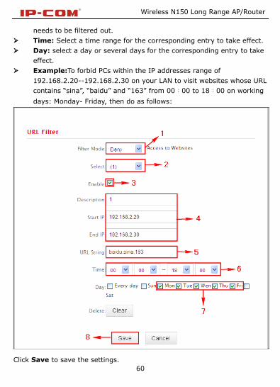
6.3 URL Filter
To better control LAN PCs, you can use the URL filter functionality to allow or
disallow such PC to access certain websites within a specified time range.
In Filter Mode, you can choose Disable, Allow Access to Websites, and Deny
Access to Websites. You will see the page below.
Filter Mode: Select Deny or Allow according to your own needs.
Deny Access to Websites: Disallow PCs at specified IP addresses to
access websites with certain URL string.
Allow Access to Websites: Allow PCs at specified IP addresses to
access websites with certain URL string.
Select: Select a number (indicating a filter rule) from the drop-down
menu. Up to 10 rules can be set.
Description: Enter a meaningful name to yourself for a new filter rule.
Start IP: Enter a starting IP address.
End IP: Enter an ending IP address.
URL String: Enter domain names or a part of a domain name that
Wireless N150 Long Range AP/Router
60
needs to be filtered out.
Time: Select a time range for the corresponding entry to take effect.
Day: select a day or several days for the corresponding entry to take
effect.
Example:To forbid PCs within the IP addresses range of
192.168.2.20--192.168.2.30 on your LAN to visit websites whose URL
contains “sina”, “baidu” and “163” from 00:00 to 18:00 on working
days: Monday- Friday, then do as follows:
Click Save to save the settings.

Wireless N150 Long Range AP/Router
61
6.4 Remote Web Management
The Remote Web management allows the Router to be configured from the
Internet by a web browser.
Enable: Select whether to enable the Remote Web-based Management
feature.
Port: Remote admin port; the port used by trusted hosts from
Internet or other external networks to access and manage the device
remotely via a web browser.
IP address:Enter a trusted IP address of a PC from Internet or other
external networks which you want to authorize to manage the device
remotely via a web browser.
Notice:
1. To access the device via port 8080, enter http://x.x.x.x:8080 where
"x.x.x.x" represents the the device's Internet IP address and 8080 is the
remote admin port. Assuming the device's Internet IP address is
220.135.211.56, then, simply replace the "x.x.x.x" with "220.135.211.56"
(namely, http://220.135.211.56:8080).
2. Leaving the IP address field at "0.0.0.0" makes the device remotely
accessible to all the PCs on Internet or other external networks; populating it
with a specific IP address, say, 218.88.93.33, makes the device only remotely
accessible to the PC at the specified IP address.
Wireless N150 Long Range AP/Router
62
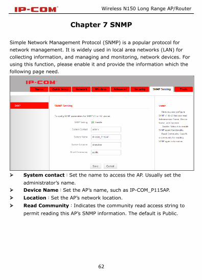
Chapter 7 SNMP
Simple Network Management Protocol (SNMP) is a popular protocol for
network management. It is widely used in local area networks (LAN) for
collecting information, and managing and monitoring, network devices. For
using this function, please enable it and provide the information which the
following page need.
System contact:Set the name to access the AP. Usually set the
administrator’s name.
Device Name:Set the AP’s name, such as IP-COM_P115AP.
Location:Set the AP’s network location.
Read Community:Indicates the community read access string to
permit reading this AP’s SNMP information. The default is Public.
Wireless N150 Long Range AP/Router
63
Chapter 8 System tools
This section focuses on how to maintain AP, including Syslog, Statistics, Time
& Date, Change Password, Backup, Restore, Firmware Update, Restore to
Factory Default, Reboot.
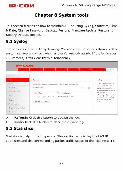
8.1 Syslog
The section is to view the system log. You can view the various statuses after
system startup and check whether there’s network attack. If the log is over
200 records, it will clear them automatically.
Refresh: Click this button to update the log.
Clear: Click this button to clear the current log.
8.2 Statistics
Statistics is only for routing mode. This section will display the LAN IP
addresses and the corresponding packet traffic status of the local network.

Wireless N150 Long Range AP/Router
64
Enable Traffic Statistics: Tick this box to enable the network user
traffic statistics. If there is no need to, we suggest turn off this function.
Refresh: Click this button to update the statistic list.
8.3 Time & Date
Wireless N150 Long Range AP/Router
65
This section is to select the time zone for your location. You can select your
own time or obtain the standard GMT time from Internet.
Sync with Internet time servers:Obtain the standard GMT time from
Internet automatically.
Sync Interval:System time synchronization interval. Please choose
according to your need, the system default cycle time is half an hour.
Time Zone:Select your time zone from the drop-down menu.
Sync with Your PC:Customize the time of the device the same with
your PC.
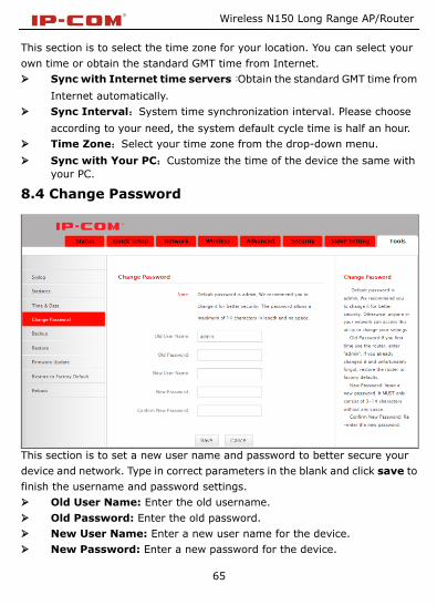
8.4 Change Password
This section is to set a new user name and password to better secure your
device and network. Type in correct parameters in the blank and click save to
finish the username and password settings.
Old User Name: Enter the old username.
Old Password: Enter the old password.
New User Name: Enter a new user name for the device.
New Password: Enter a new password for the device.

Wireless N150 Long Range AP/Router
66
Confirm New Password: Re-enter to confirm the new password.
Note:It is highly recommended to change the password to secure your
network and the device.
8.5 Backup
Backup: Click this button to back up the device’s configurations.
8.6 Restore

Wireless N150 Long Range AP/Router
67
Choose File: Click this button to browse the directory where you backup or
save the device’s settings.
Restore: Click this button to restore the device’s configurations.
8.7 Firmware Update
By upgrading the router's software, you will get more stable version and
appreciation of the routing function.
Firmware Update Steps:
On the Firmware Upgrade screen, click the Choose File button and find the
new firmware file.
Click Update button, and follow the on-screen instructions.
After the upgrade is completed, the device will reboot automatically.
Note: Do not power off the system during the firmware upgrade to avoid
damaging the device. The upgrade process will take a few minutes, please
wait patiently.
Wireless N150 Long Range AP/Router
68
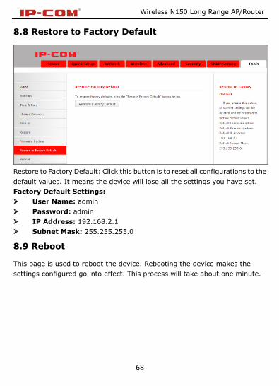
8.8 Restore to Factory Default
Restore to Factory Default: Click this button is to reset all configurations to the
default values. It means the device will lose all the settings you have set.
Factory Default Settings:
User Name: admin
Password: admin
IP Address: 192.168.2.1
Subnet Mask: 255.255.255.0
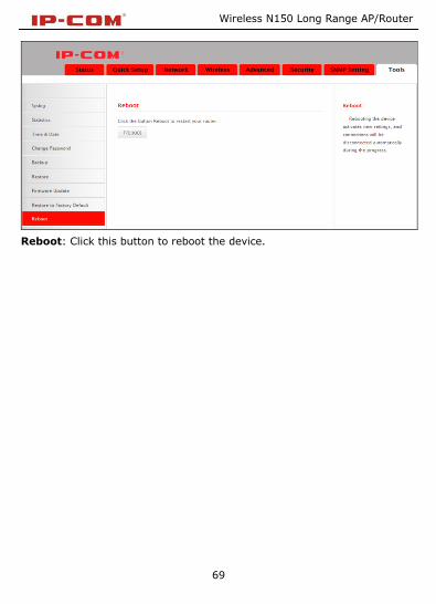
8.9 Reboot
This page is used to reboot the device. Rebooting the device makes the
settings configured go into effect. This process will take about one minute.
Wireless N150 Long Range AP/Router
69
Reboot: Click this button to reboot the device.

Wireless N150 Long Range AP/Router
70
Appendix 1 TCP/IP Settings
If you are using Windows XP, do as follows:
1. From the desktop, click Start > Control Panel > Network and Internet
Connections.

Wireless N150 Long Range AP/Router
71
2. Right-click on the Local Area Connection and select Properties.

Wireless N150 Long Range AP/Router
72
3. Select Internet Protocol (TCP/IP) and click Properties.
Wireless N150 Long Range AP/Router
73
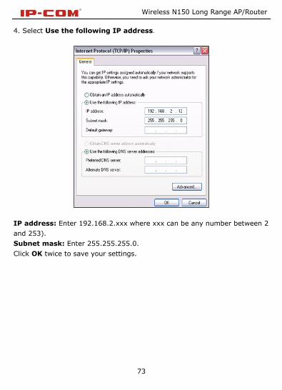
4. Select Use the following IP address.
IP address: Enter 192.168.2.xxx where xxx can be any number between 2
and 253).
Subnet mask: Enter 255.255.255.0.
Click OK twice to save your settings.
Wireless N150 Long Range AP/Router
74
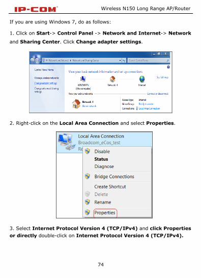
If you are using Windows 7, do as follows:
1. Click on Start-> Control Panel -> Network and Internet-> Network
and Sharing Center. Click Change adapter settings.
2. Right-click on the Local Area Connection and select Properties.
3. Select Internet Protocol Version 4 (TCP/IPv4) and click Properties
or directly double-click on Internet Protocol Version 4 (TCP/IPv4).

Wireless N150 Long Range AP/Router
75
4. Select Use the following IP address.

Wireless N150 Long Range AP/Router
76
IP address: Enter 192.168.2.xxx where xxx can be any number between 2
and 253).
Subnet mask: Enter 255.255.255.0.
Click OK twice to save your settings.

Wireless N150 Long Range AP/Router
77
Appendix 2 Glossary
Channel
A communication channel, also known as channel, refers either to a physical
transmission medium such as a wire or to a logical connection over a
multiplexed medium such as a radio channel. It is used to transfer an
information signal, such as a digital bit stream, from one or more transmitters
to one or more receivers. If there is only one AP in the range, select any
channel you like. The default is Auto.
If there are several APs coexisting in the same area, it is advisable that you
select a different channel for each AP to operate on, minimizing the
interference between neighboring APs. For example, if 3 American- standard
APs coexist in one area, you can set their channels respectively to 1, 6 and 11
to avoid mutual interference.
SSID
Service set identifier (SSID) is used to identify a particular 802.11 wireless
LAN. It is the name of a specific wireless network. To let your wireless network
adapter roam among different APs, you must set all Aps’ SSID to the same
name.
Wired Equivalent Privacy (WEP) is a security algorithm for IEEE 802.11
wireless networks with the intention to provide data confidentiality
comparable to that of a traditional wired network .WEP, recognizable by the
key of 10 or 26 hexadecimal digits, is widely in use. WEP uses the stream
cipher RC4 for confidentiality,[5] and the CRC-32 checksum for integrity.
Standard 64-bit WEP uses a 40-bit key (also known as WEP-40), which is
concatenated with a 24-bit initialization vector (IV) to form the RC4 key. The
extended 128-bit WEP protocol uses a 104-bit key size (WEP-104). A 152-bit
WEP is available from some vendors. Static WEP encryption allows to include 4 WEP

Wireless N150 Long Range AP/Router
78
Keys while dynamic WEP encryption changes WEP key dynamically.
WPA/WPA2
The WPA protocol implements the majority of the IEEE 802.11i standard. It
enhances data encryption through the Temporal Key Integrity Protocol (TKIP)
which is a 128-bit per-packet key, meaning that it dynamically generates a
new key for each packet. WPA also includes a message integrity check feature
to prevent data packets from being hampered with. Only authorized network
users can access the wireless network.
The later WPA2 protocol features compliance with the full IEEE 802.11i
standard and uses Advanced Encryption Standard (AES) in addition to TKIP
encryption protocol to guarantee better security than that provided by WEP or
WPA. Currently, WPA is supported by Windows XP SP1.
Wireless N150 Long Range AP/Router
79
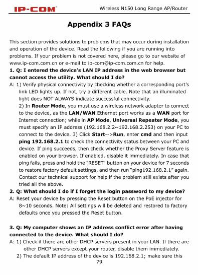
Appendix 3 FAQs
This section provides solutions to problems that may occur during installation
and operation of the device. Read the following if you are running into
problems. If your problem is not covered here, please go to our website of
www.ip-com.com.cn or e-mail to [email protected] for help.
1. Q: I entered the device’s LAN IP address in the web browser but
cannot access the utility. What should I do?
A: 1) Verify physical connectivity by checking whether a corresponding port’s
link LED lights up. If not, try a different cable. Note that an illuminated
light does NOT ALWAYS indicate successful connectivity.
2) In Router Mode, you must use a wireless network adapter to connect
to the device, as the LAN/WAN Ethernet port works as a WAN port for
Internet connection; while in AP Mode, Universal Repeater Mode, you
must specify an IP address (192.168.2.2~192.168.2.253) on your PC to
connect to the device. 3) Click Start-->Run, enter cmd and then input
ping 192.168.2.1 to check the connectivity status between your PC and
device. If ping succeeds, then check whether the Proxy Server feature is
enabled on your browser. If enabled, disable it immediately. In case that
ping fails, press and hold the "RESET" button on your device for 7 seconds
to restore factory default settings, and then run “ping192.168.2.1” again.
Contact our technical support for help if the problem still exists after you
tried all the above.
2. Q: What should I do if I forget the login password to my device?
A: Reset your device by pressing the Reset button on the PoE injector for
8~10 seconds. Note: All settings will be deleted and restored to factory
defaults once you pressed the Reset button.
3. Q: My computer shows an IP address conflict error after having
connected to the device. What should I do?
A: 1) Check if there are other DHCP servers present in your LAN. If there are
other DHCP servers except your router, disable them immediately.
2) The default IP address of the device is 192.168.2.1; make sure this

Wireless N150 Long Range AP/Router
80
address is not used by another PC or device. In case that two computers
or devices share the same IP addresses, change either to a different
address.
4. Q: My computer can neither log in to the device nor access Internet,
and there is a yellow triangle with an exclamation mark shown in the
network adapter icon on the right bottom corner of my computer
desktop; how am I supposed to deal with it?
A: This problem occurs because your network card has not been assigned with
an IP address. If your computer is set to obtain an IP address automatically,
please ensure that the router's DHCP function is enabled. DHCP can
automatically assign an IP address to your computer. If there is no DHCP
server available on your network, please set a static IP address and fill in
gateway and DNS, otherwise you cannot access Internet.
5. Q: How do I share resources on my computer with users on
Internet through the device?
A: To let Internet users access internal servers on your LAN such as e-mail
server, Web, FTP, via the device, use the "Virtual Server" feature. To do so,
follow steps below:
Step 1: Create your internal server, make sure the LAN users can access
these servers and you need to know related service ports, for example,
port for Web server is 80; FTP is 21; SMTP is 25 and POP3 is 110.
Step 2: Click “Virtual Server” and select “Port Range Forwarding” (also
known as Port Forwarding on some devices) on device’s web interface.
Step 3: Input the Start Port/External Port, say, 80.
Step 4: Input the End Port/Internal Port, say, 80.
Input the internal server’s IP address. For example, assuming that your
Web server’s IP address is 192.168. 2.10, then simply input it.
Step 5: Select a communication protocol used by your internal host: TCP,
UDP or ICMP and enable the rule.
Step 6: Save your settings.

Wireless N150 Long Range AP/Router
81
For your reference, we collected a list of some well-known service ports as
follows:
For your reference, we collected a list of some well-known service ports as
follows:
Server Protocol Service Port
Web Server TCP 80
FTP Server TCP 21
Telnet TCP 23
NetMeeting TCP 1503、1720
SKype TCP/UDP
File Send:6891-6900(TCP)
Voice:1863、6901(TCP)
Voice:1863、5190(UDP)
PPTP VPN TCP 1723
Iphone5.0 TCP 22555
SMTP TCP 25
POP3 TCP 110
If your problems are not covered here, please feel free to go to
www.ip-com.com.cn . to find solutions or email your problems to:
[email protected] . We will be more than happy to help you out as soon
as possible.
IP-COM Networks, Inc
No. 34-1 Shilong Road
Shiyan Town, Bao,an District
Shenzhen 518108,China
Tel: +86-755-8170-7803
Fax: +86-755-2765-7178
Email: [email protected]
http://www.ip-com.com.cn

Wireless N150 Long Range AP/Router
82
Appendix 4 Safety and Emission Statement
CE Mark Warning
This is a Class B product In a domestic environment,this product may cause
radio interference,in which case the user may be required to take adequate
measures.This device complies with EU 1999/5/EC.
NOTE:(1)The manufacturer is not responsible for any radio or TV interference
caused by unauthorized modifications to this equipment.(2) To avoid
unnecessary radiation interference, it is recommended to use a shielded RJ45
cable
FCC Statement
This equipment has been tested and found to comply with the limits for a
Class A digital device, pursuant to part 15 of the FCC Rules. These limits are
designed to pro-vide reasonable protection against harmful interference
when the equipment is operate din a commercial environment. This
equipment generates, uses, and can radiate radiofrequency energy and, if not
installed and used in accordance with the instruction manual, may cause
harmful interference to radio communications. Operation of this equipment in
a residential area is likely to cause harmful interference in which case the user

Wireless N150 Long Range AP/Router
83
will be required to correct the interference at his own expense.
FCC Caution: Any changes or modifications not expressly approved by the
party responsible for compliance could void the user's authority to operate
this equipment.
This device complies with part 15 of the FCC Rules.
Operation is subject to the following two conditions:
(1) This device may not cause harmful interference, and(2) this device must
accept any interference received, including interference that may cause
undesired operation. The manufacturer is not responsible for any radio or TV
interference caused by unauthorized modifications to this equipment.
NOTE:(1)The manufacturer is not responsible for any radio or TV interference
caused by unauthorized modifications to this equipment.(2) To avoid
unnecessary radiation interference, it is recommended to use a shielded RJ45
cable