Embed Size (px)
Citation preview
Wireless, Mobile Networks 6-1
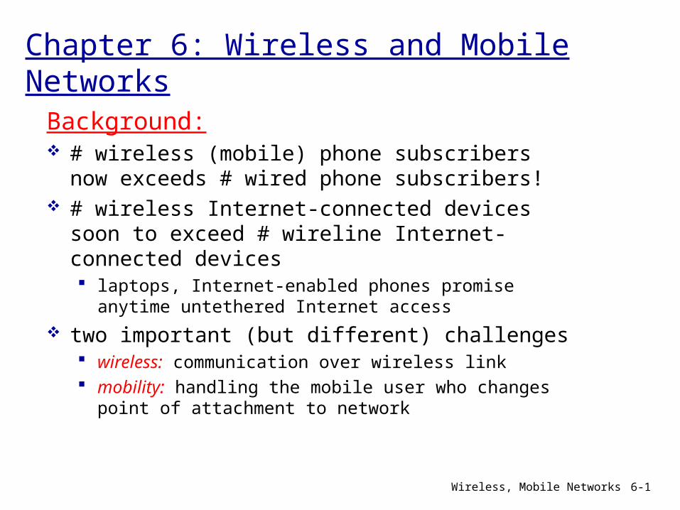
Chapter 6: Wireless and Mobile NetworksBackground: # wireless (mobile) phone subscribers now exceeds # wired phone subscribers!
# wireless Internet-connected devices soon to exceed # wireline Internet-connected devices laptops, Internet-enabled phones promise anytime untethered Internet access
two important (but different) challenges wireless: communication over wireless link mobility: handling the mobile user who changes point of attachment to network
Wireless, Mobile Networks 6-2
Chapter 6 outline
6.1 Introduction
Wireless6.2 Wireless links, characteristics CDMA
6.3 IEEE 802.11 wireless LANs (“Wi-Fi”)
6.4 Cellular Internet Access architecture standards (e.g., GSM)
Mobility6.5 Principles: addressing and routing to mobile users
6.6 Mobile IP6.7 Handling mobility in cellular networks
6.8 Mobility and higher-layer protocols
6.9 Summary
Wireless, Mobile Networks 6-3
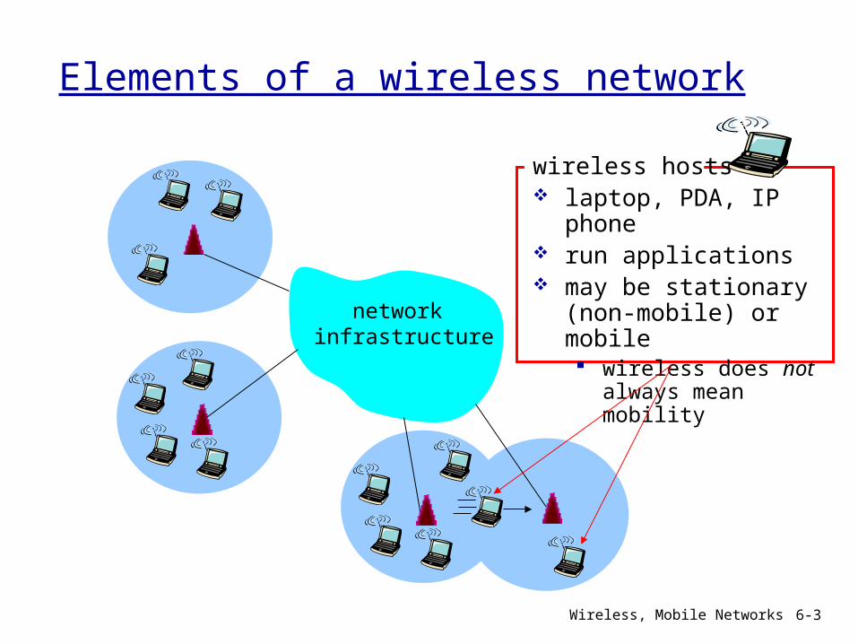
Elements of a wireless network
network infrastructure
wireless hosts laptop, PDA, IP
phone run applications may be stationary
(non-mobile) or mobile wireless does not
always mean mobility
Wireless, Mobile Networks 6-4
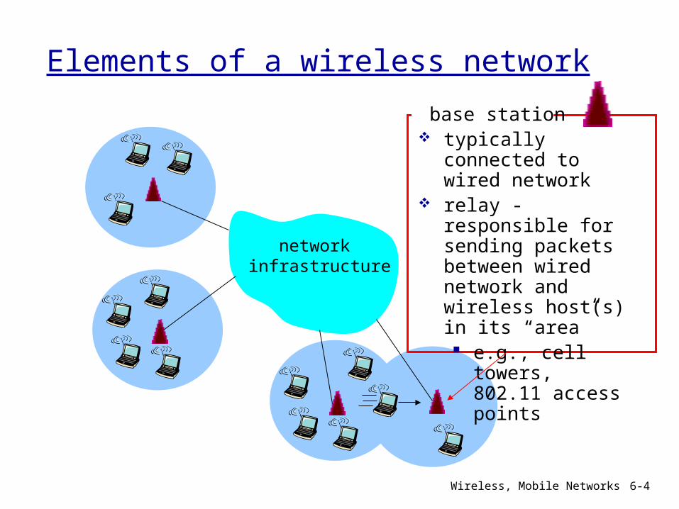
Elements of a wireless network
network infrastructure
base station typically
connected to wired network
relay - responsible for sending packets between wired network and wireless host(s) in its “area” e.g., cell towers, 802.11 access points
Wireless, Mobile Networks 6-5
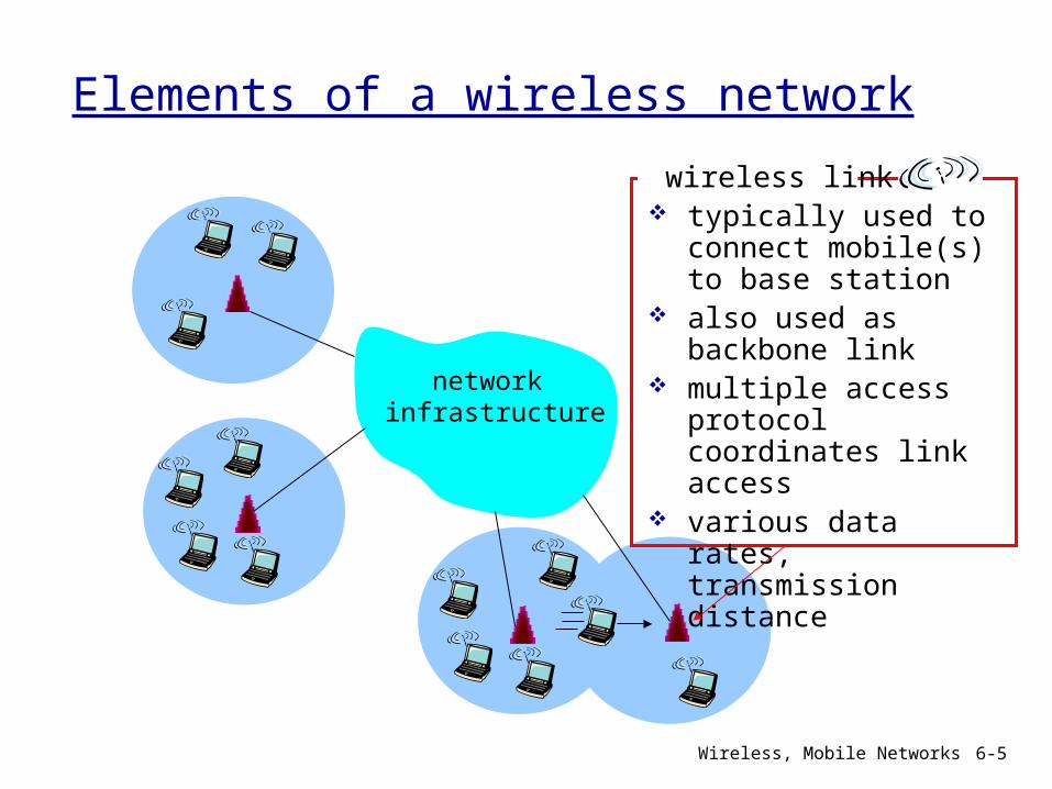
Elements of a wireless network
network infrastructure
wireless link typically used to
connect mobile(s) to base station
also used as backbone link
multiple access protocol coordinates link access
various data rates, transmission distance
Wireless, Mobile Networks 6-6
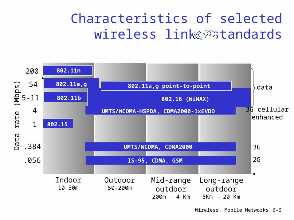
Characteristics of selected wireless link standards
Indoor10-30m
Outdoor50-200m
Mid-rangeoutdoor
200m – 4 Km
Long-rangeoutdoor
5Km – 20 Km
.056
.384
1
4
5-11
54
IS-95, CDMA, GSM 2G
UMTS/WCDMA, CDMA2000 3G
802.15
802.11b
802.11a,g
UMTS/WCDMA-HSPDA, CDMA2000-1xEVDO 3G cellularenhanced
802.16 (WiMAX)
802.11a,g point-to-point
200 802.11n
Dat
a ra
te (
Mbp
s)
data
Wireless, Mobile Networks 6-7
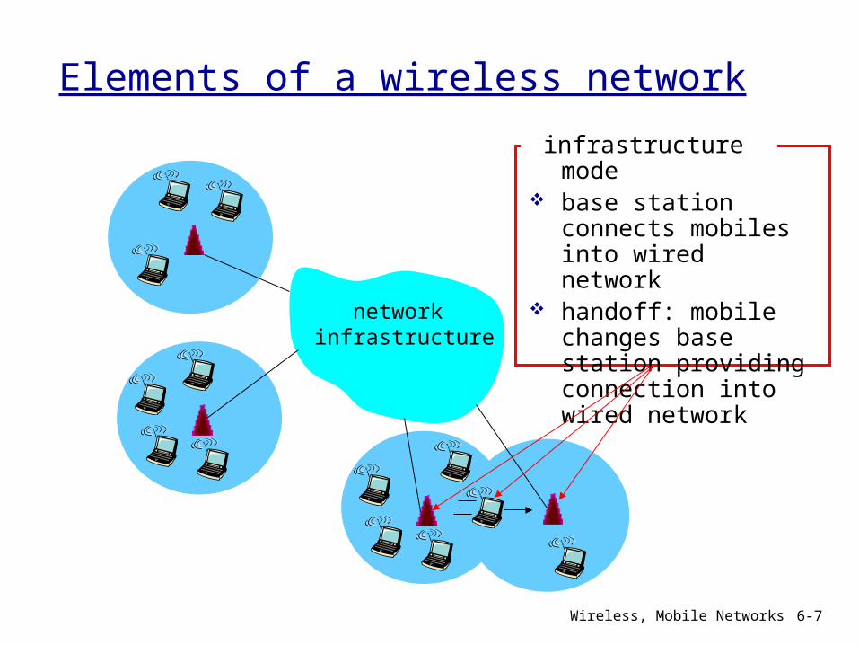
Elements of a wireless network
network infrastructure
infrastructure mode
base station connects mobiles into wired network
handoff: mobile changes base station providing connection into wired network
Wireless, Mobile Networks 6-8
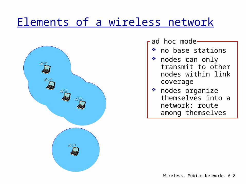
Elements of a wireless network
ad hoc mode no base stations nodes can only
transmit to other nodes within link coverage
nodes organize themselves into a network: route among themselves
Wireless, Mobile Networks 6-9
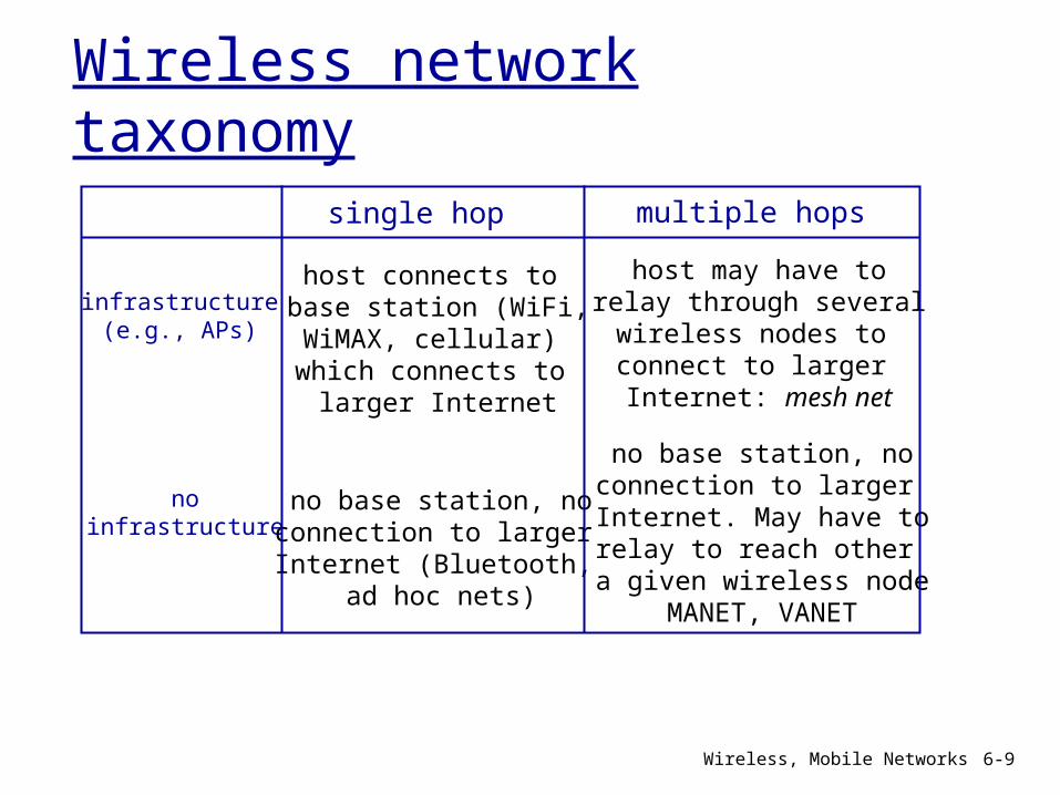
Wireless network taxonomy
single hop multiple hops
infrastructure(e.g., APs)
noinfrastructure
host connects to base station (WiFi,WiMAX, cellular) which connects to larger Internet
no base station, noconnection to larger Internet (Bluetooth,
ad hoc nets)
host may have torelay through severalwireless nodes to connect to larger Internet: mesh net
no base station, noconnection to larger Internet. May have torelay to reach other a given wireless node
MANET, VANET
Wireless, Mobile Networks 6-10
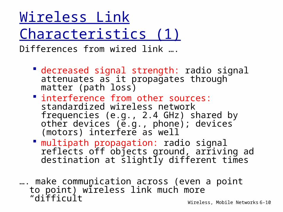
Wireless Link Characteristics (1)Differences from wired link ….
decreased signal strength: radio signal attenuates as it propagates through matter (path loss)
interference from other sources: standardized wireless network frequencies (e.g., 2.4 GHz) shared by other devices (e.g., phone); devices (motors) interfere as well
multipath propagation: radio signal reflects off objects ground, arriving ad destination at slightly different times
…. make communication across (even a point to point) wireless link much more “difficult”
Wireless, Mobile Networks 6-11
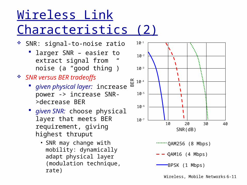
Wireless Link Characteristics (2) SNR: signal-to-noise ratio
larger SNR – easier to extract signal from noise (a “good thing”)
SNR versus BER tradeoffs given physical layer: increase power -> increase SNR->decrease BER
given SNR: choose physical layer that meets BER requirement, giving highest thruput• SNR may change with mobility: dynamically adapt physical layer (modulation technique, rate)
10 20 30 40
QAM256 (8 Mbps)
QAM16 (4 Mbps)
BPSK (1 Mbps)
SNR(dB)B
ER
10-1
10-2
10-3
10-5
10-6
10-7
10-4
Wireless, Mobile Networks 6-12
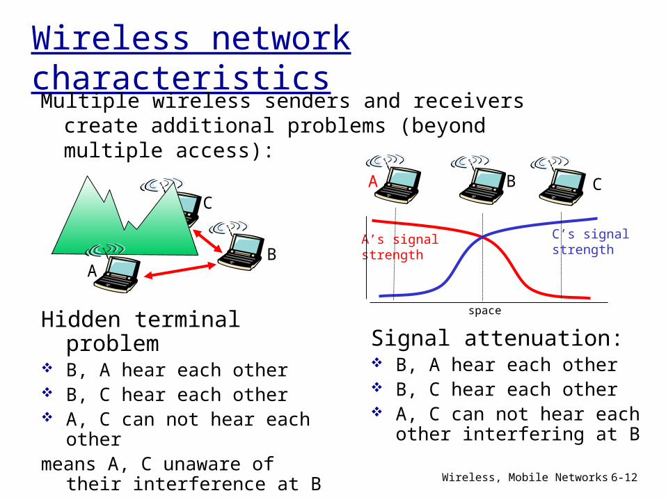
Wireless network characteristicsMultiple wireless senders and receivers create additional problems (beyond multiple access):
AB
C
Hidden terminal problem
B, A hear each other B, C hear each other A, C can not hear each
othermeans A, C unaware of
their interference at B
A B C
A’s signalstrength
space
C’s signalstrength
Signal attenuation: B, A hear each other B, C hear each other A, C can not hear each
other interfering at B
Wireless, Mobile Networks 6-13
Code Division Multiple Access (CDMA)
used in several wireless broadcast channels (cellular, satellite, etc) standards
unique “code” assigned to each user; i.e., code set partitioning
all users share same frequency, but each user has own “chipping” sequence (i.e., code) to encode data
encoded signal = (original data) X (chipping sequence)
decoding: inner-product of encoded signal and chipping sequence
allows multiple users to “coexist” and transmit simultaneously with minimal interference (if codes are “orthogonal”)
Wireless, Mobile Networks 6-14
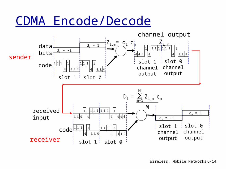
CDMA Encode/Decode
slot 1 slot 0
d1 = -1
1 1 1 1
1- 1- 1- 1-
Zi,m= di.cmd0 = 1
1 1 1 1
1- 1- 1- 1-
1 1 1 1
1- 1- 1- 1-
1 1 11
1-1- 1- 1-
slot 0channeloutput
slot 1channeloutput
channel output Zi,m
sendercode
databits
slot 1 slot 0
d1 = -1d0 = 1
1 1 1 1
1- 1- 1- 1-
1 1 1 1
1- 1- 1- 1-
1 1 1 1
1- 1- 1- 1-
1 1 11
1-1- 1- 1-
slot 0channeloutput
slot 1channeloutputreceiver
code
receivedinput
Di = Zi,m.cmm=1
M
M
Wireless, Mobile Networks 6-15
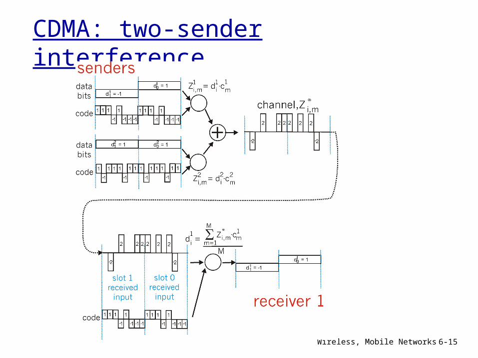
CDMA: two-sender interference
Wireless, Mobile Networks 6-16
Chapter 6 outline
6.1 Introduction
Wireless6.2 Wireless links, characteristics CDMA
6.3 IEEE 802.11 wireless LANs (“Wi-Fi”)
6.4 Cellular Internet Access architecture standards (e.g., GSM)
Mobility6.5 Principles: addressing and routing to mobile users
6.6 Mobile IP6.7 Handling mobility in cellular networks
6.8 Mobility and higher-layer protocols
6.9 Summary
Wireless, Mobile Networks 6-17
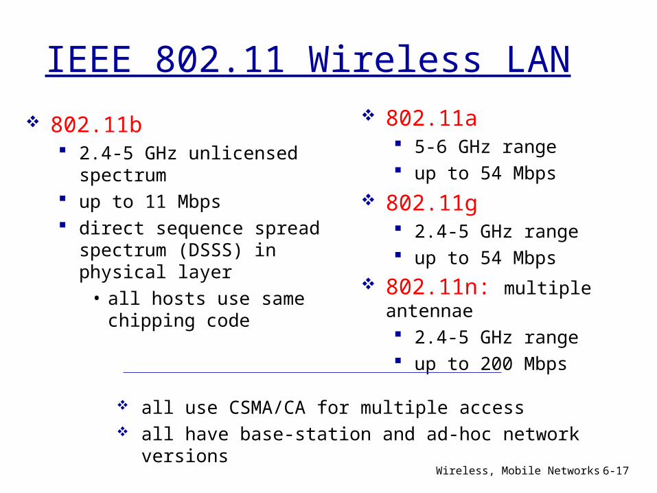
IEEE 802.11 Wireless LAN
802.11b 2.4-5 GHz unlicensed spectrum
up to 11 Mbps direct sequence spread spectrum (DSSS) in physical layer• all hosts use same chipping code
802.11a 5-6 GHz range up to 54 Mbps
802.11g 2.4-5 GHz range up to 54 Mbps
802.11n: multiple antennae 2.4-5 GHz range up to 200 Mbps
all use CSMA/CA for multiple access all have base-station and ad-hoc
network versions
Wireless, Mobile Networks 6-18
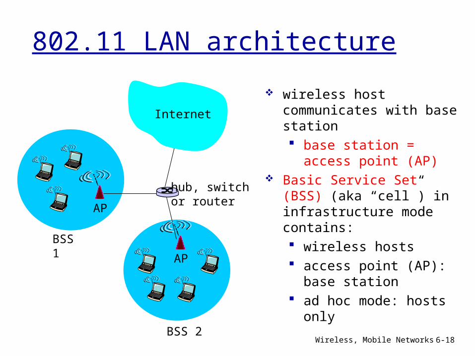
802.11 LAN architecture
wireless host communicates with base station base station = access point (AP)
Basic Service Set (BSS) (aka “cell”) in infrastructure mode contains: wireless hosts access point (AP): base station
ad hoc mode: hosts only
BSS 1
BSS 2
Internet
hub, switchor routerAP
AP
Wireless, Mobile Networks 6-19
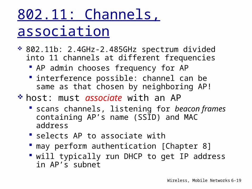
802.11: Channels, association 802.11b: 2.4GHz-2.485GHz spectrum divided into 11 channels at different frequencies AP admin chooses frequency for AP interference possible: channel can be same as that chosen by neighboring AP!
host: must associate with an AP scans channels, listening for beacon frames containing AP’s name (SSID) and MAC address
selects AP to associate with may perform authentication [Chapter 8] will typically run DHCP to get IP address in AP’s subnet
Wireless, Mobile Networks 6-20
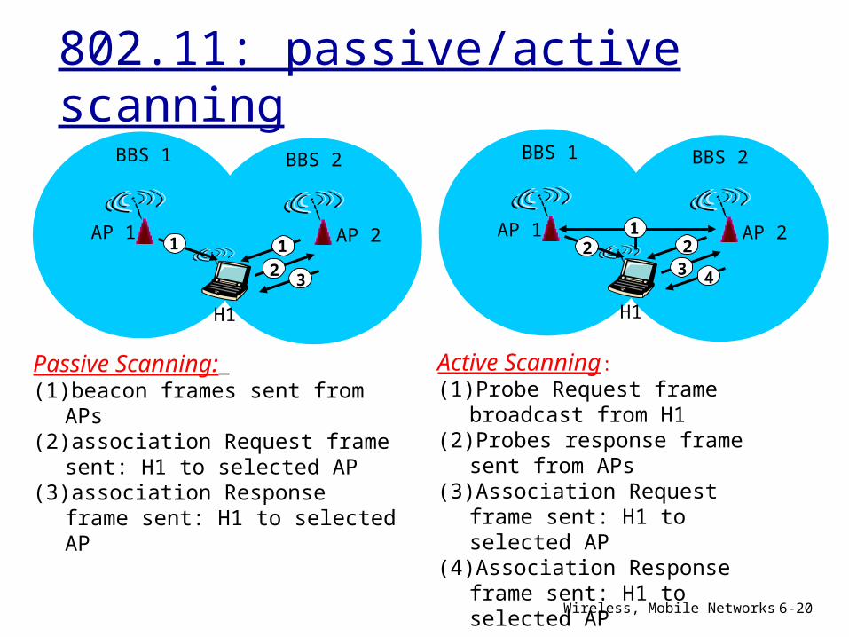
802.11: passive/active scanning
AP 2AP 1
H1
BBS 2BBS 1
122
3 4
Active Scanning: (1) Probe Request frame broadcast
from H1(2) Probes response frame sent from
APs(3) Association Request frame sent:
H1 to selected AP (4) Association Response frame
sent: H1 to selected AP
AP 2AP 1
H1
BBS 2BBS 1
1
23
1
Passive Scanning: (1) beacon frames sent from APs(2) association Request frame sent:
H1 to selected AP (3) association Response frame sent:
H1 to selected AP
Wireless, Mobile Networks 6-21
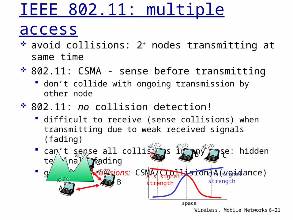
IEEE 802.11: multiple access avoid collisions: 2+ nodes transmitting at same time
802.11: CSMA - sense before transmitting don’t collide with ongoing transmission by other node
802.11: no collision detection! difficult to receive (sense collisions) when transmitting due to weak received signals (fading)
can’t sense all collisions in any case: hidden terminal, fading
goal: avoid collisions: CSMA/C(ollision)A(voidance)
AB
CA B C
A’s signalstrength
space
C’s signalstrength
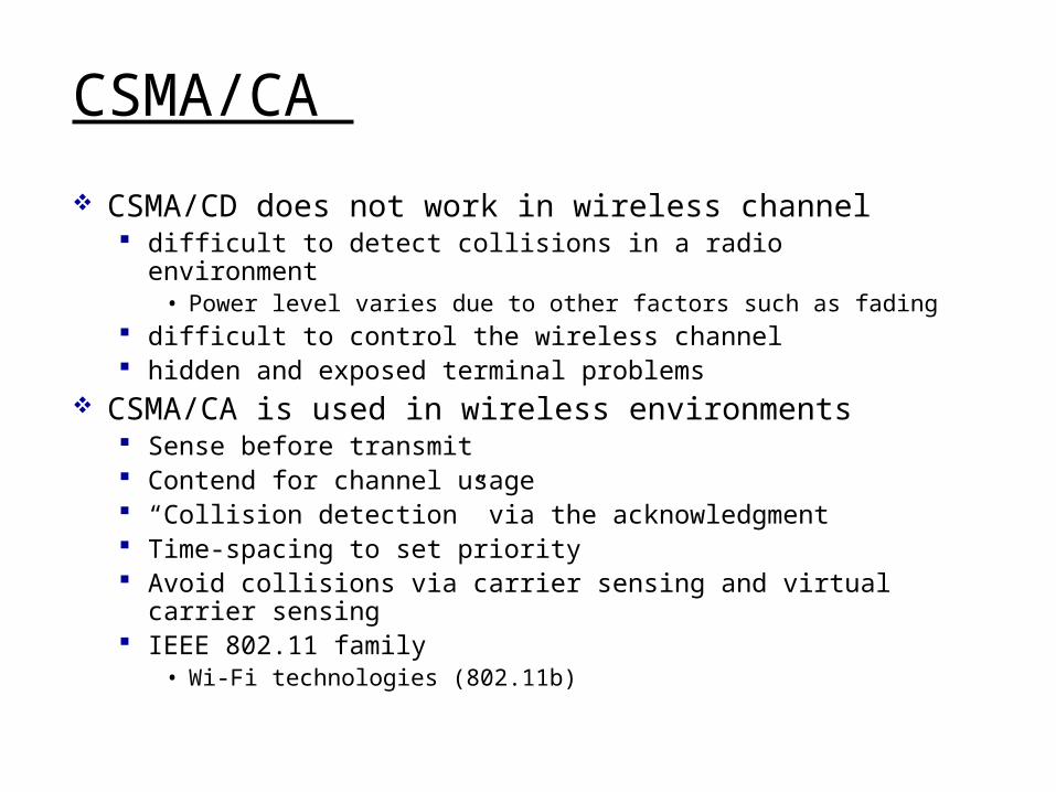
CSMA/CA
CSMA/CD does not work in wireless channel difficult to detect collisions in a radio environment • Power level varies due to other factors such as fading
difficult to control the wireless channel hidden and exposed terminal problems
CSMA/CA is used in wireless environments Sense before transmit Contend for channel usage “Collision detection” via the acknowledgment Time-spacing to set priority Avoid collisions via carrier sensing and virtual carrier sensing
IEEE 802.11 family• Wi-Fi technologies (802.11b)
CSMA/CA
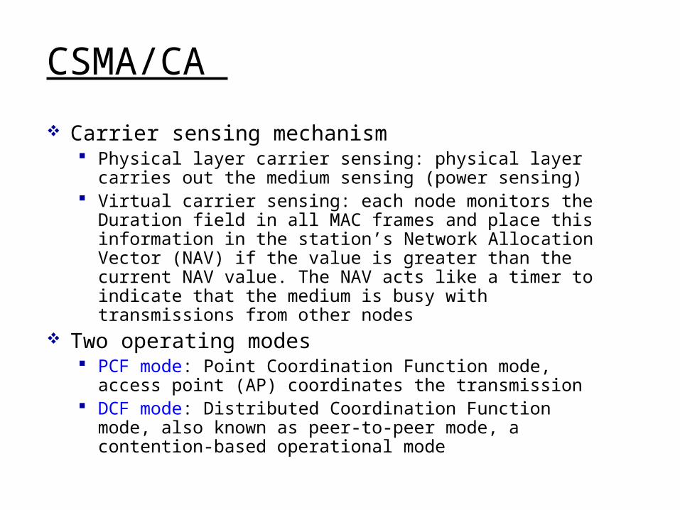
Carrier sensing mechanism Physical layer carrier sensing: physical layer carries out the medium sensing (power sensing)
Virtual carrier sensing: each node monitors the Duration field in all MAC frames and place this information in the station’s Network Allocation Vector (NAV) if the value is greater than the current NAV value. The NAV acts like a timer to indicate that the medium is busy with transmissions from other nodes
Two operating modes PCF mode: Point Coordination Function mode, access point (AP) coordinates the transmission
DCF mode: Distributed Coordination Function mode, also known as peer-to-peer mode, a contention-based operational mode
CSMA/CA
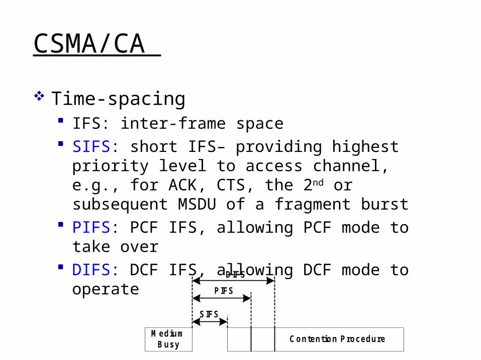
Time-spacing IFS: inter-frame space SIFS: short IFS– providing highest priority level to access channel, e.g., for ACK, CTS, the 2nd or subsequent MSDU of a fragment burst
PIFS: PCF IFS, allowing PCF mode to take over
DIFS: DCF IFS, allowing DCF mode to operate
MediumBusy
Contention Procedure
SIFS
PIFS
DIFS
Wireless, Mobile Networks 6-25
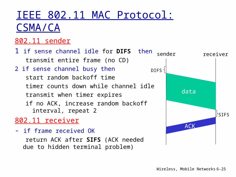
IEEE 802.11 MAC Protocol: CSMA/CA802.11 sender1 if sense channel idle for DIFS then
transmit entire frame (no CD)2 if sense channel busy then
start random backoff timetimer counts down while channel idle
transmit when timer expiresif no ACK, increase random backoff interval, repeat 2
802.11 receiver- if frame received OK return ACK after SIFS (ACK needed
due to hidden terminal problem)
sender receiver
DIFS
data
SIFS
ACK
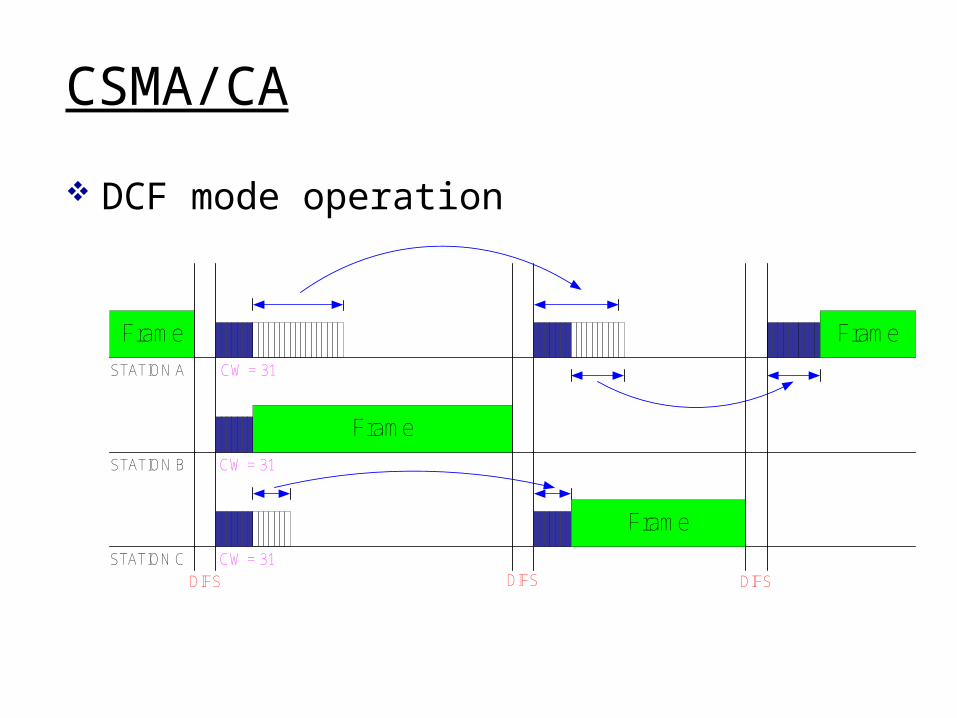
CSMA/CA
DCF mode operation
Frame
Frame
Frame
Frame
STATION A
STATION B
STATION C
DIFS DIFS DIFS
CW = 31
CW = 31
CW = 31
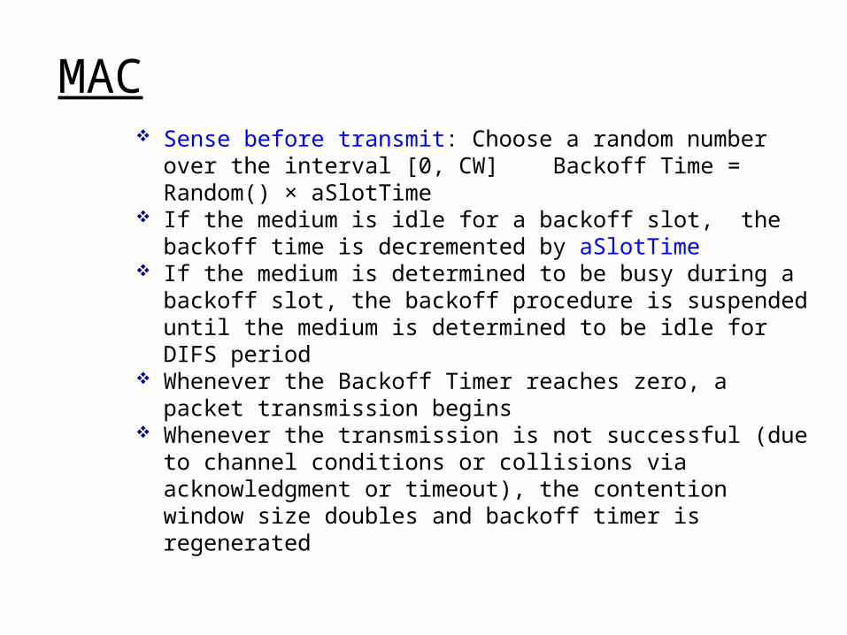
MAC Sense before transmit: Choose a random number over
the interval [0, CW] Backoff Time = Random() × aSlotTime
If the medium is idle for a backoff slot, the backoff time is decremented by aSlotTime
If the medium is determined to be busy during a backoff slot, the backoff procedure is suspended until the medium is determined to be idle for DIFS period
Whenever the Backoff Timer reaches zero, a packet transmission begins
Whenever the transmission is not successful (due to channel conditions or collisions via acknowledgment or timeout), the contention window size doubles and backoff timer is regenerated
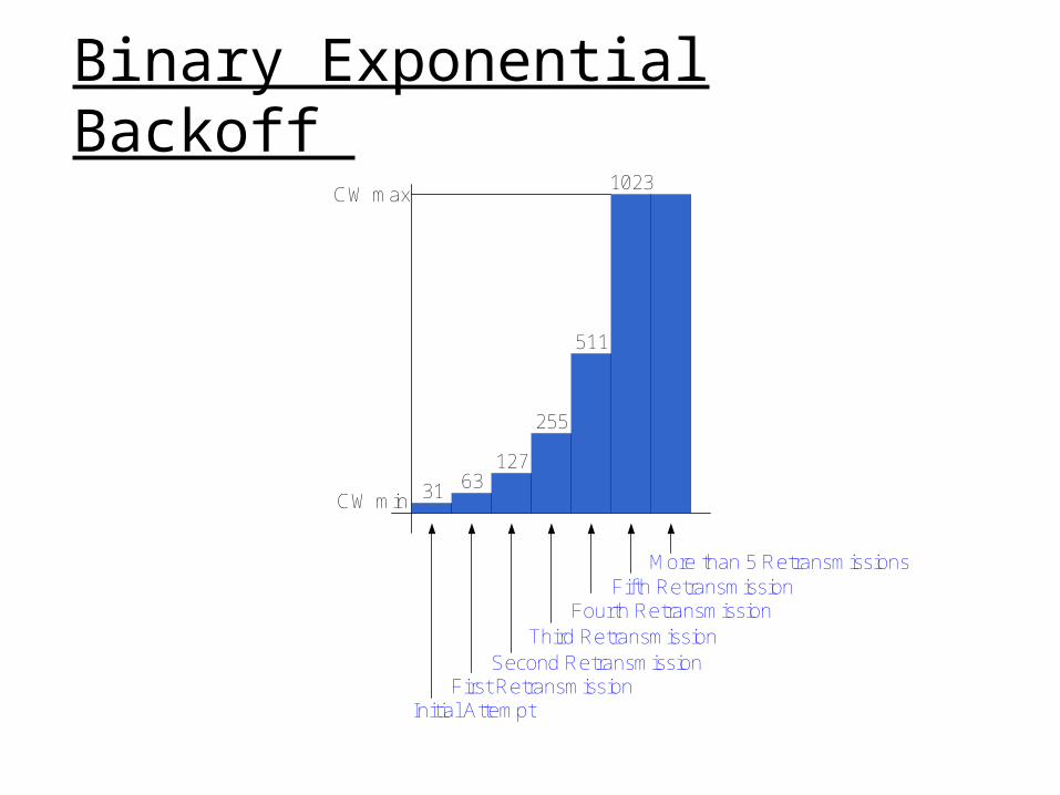
Binary Exponential Backoff
31 63127
255
511
1023CW max
CW min
More than 5 RetransmissionsFifth Retransmission
Fourth RetransmissionThird Retransmission
Second RetransmissionFirst Retransmission
Initial Attempt
Binary Exponential Backoff Algorithm for delayed transmission: random period of time for all contention-based MAC
Binary exponential backoff algorithm: Wnenver a transmission failure occurs, set current contention window size CW=2 CW (starting with CW=CWmin), pick random number from [0, CW], say, j, then set backoff time=j*aSlotTime
Wireless, Mobile Networks 6-30
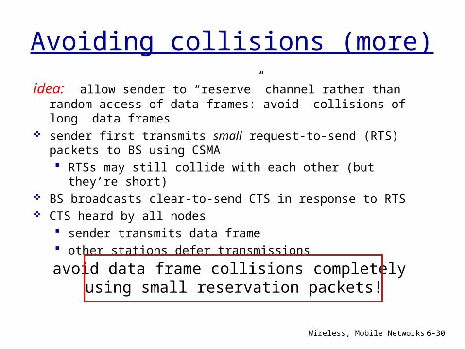
Avoiding collisions (more)
idea: allow sender to “reserve” channel rather than random access of data frames: avoid collisions of long data frames
sender first transmits small request-to-send (RTS) packets to BS using CSMA RTSs may still collide with each other (but they’re short)
BS broadcasts clear-to-send CTS in response to RTS CTS heard by all nodes
sender transmits data frame other stations defer transmissions
avoid data frame collisions completely using small reservation packets!
Wireless, Mobile Networks 6-31
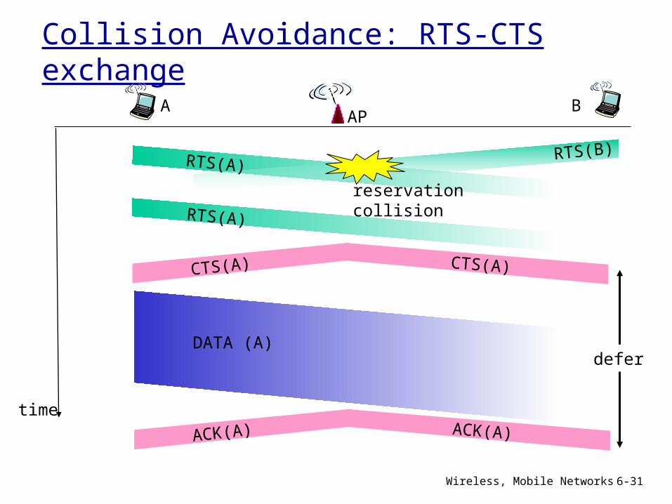
Collision Avoidance: RTS-CTS exchange
APA B
time
RTS(A)RTS(B)
RTS(A)
CTS(A) CTS(A)
DATA (A)
ACK(A) ACK(A)
reservation collision
defer
CSMA/CA with RTS/CTS
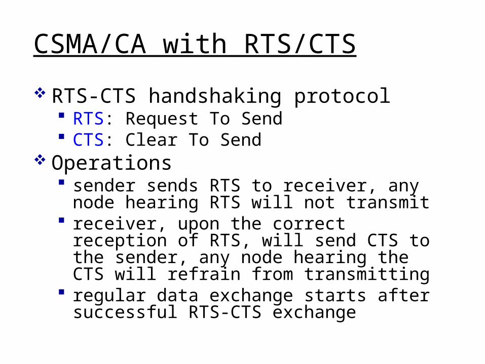
RTS-CTS handshaking protocol RTS: Request To Send CTS: Clear To Send
Operations sender sends RTS to receiver, any node hearing RTS will not transmit
receiver, upon the correct reception of RTS, will send CTS to the sender, any node hearing the CTS will refrain from transmitting
regular data exchange starts after successful RTS-CTS exchange
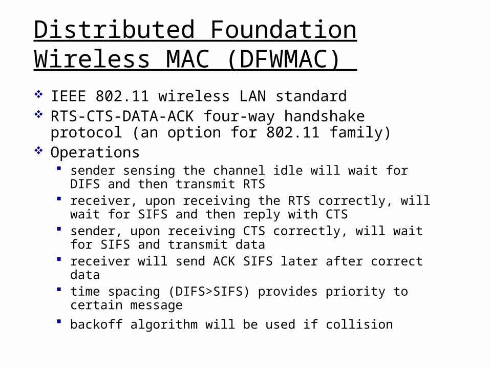
Distributed Foundation Wireless MAC (DFWMAC) IEEE 802.11 wireless LAN standard RTS-CTS-DATA-ACK four-way handshake protocol (an option for 802.11 family)
Operations sender sensing the channel idle will wait for DIFS and then transmit RTS
receiver, upon receiving the RTS correctly, will wait for SIFS and then reply with CTS
sender, upon receiving CTS correctly, will wait for SIFS and transmit data
receiver will send ACK SIFS later after correct data
time spacing (DIFS>SIFS) provides priority to certain message
backoff algorithm will be used if collision
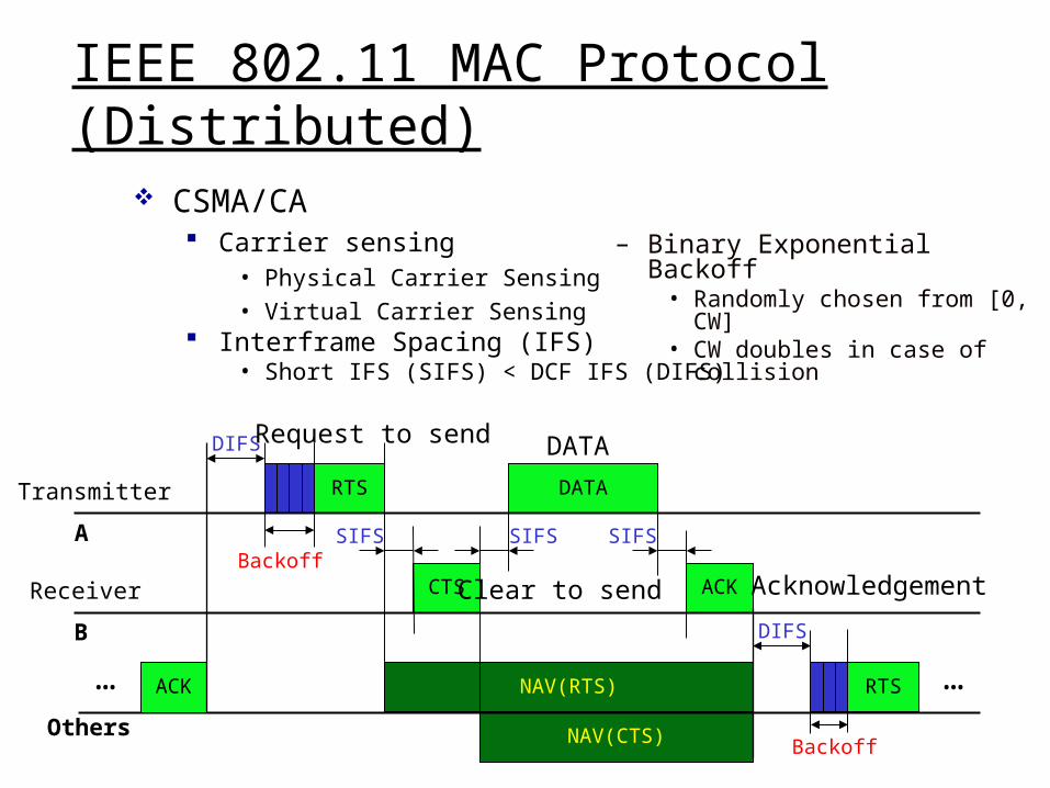
IEEE 802.11 MAC Protocol (Distributed)
CSMA/CA Carrier sensing
• Physical Carrier Sensing• Virtual Carrier Sensing
Interframe Spacing (IFS)• Short IFS (SIFS) < DCF IFS (DIFS)
DIFS
RTS
BackoffCTS
SIFS SIFS
DATA
SIFS
ACK
NAV(RTS)
NAV(CTS)
DIFS
RTS …
Backoff
– Binary Exponential Backoff• Randomly chosen from [0, CW]• CW doubles in case of collision
Transmitter
Receiver
Others
B
A
ACK…
Request to send
Clear to send Acknowledgement
DATA
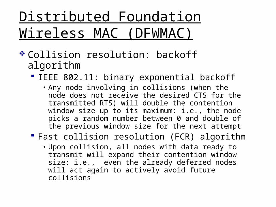
Distributed Foundation Wireless MAC (DFWMAC) Collision resolution: backoff algorithm IEEE 802.11: binary exponential backoff
• Any node involving in collisions (when the node does not receive the desired CTS for the transmitted RTS) will double the contention window size up to its maximum: i.e., the node picks a random number between 0 and double of the previous window size for the next attempt
Fast collision resolution (FCR) algorithm• Upon collision, all nodes with data ready to transmit will expand their contention window size: i.e., even the already deferred nodes will act again to actively avoid future collisions
Hidden Terminal Problem
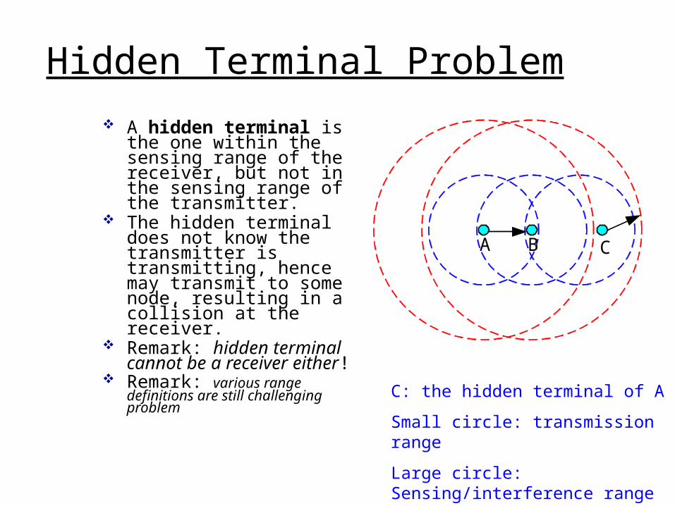
A hidden terminal is the one within the sensing range of the receiver, but not in the sensing range of the transmitter.
The hidden terminal does not know the transmitter is transmitting, hence may transmit to some node, resulting in a collision at the receiver.
Remark: hidden terminal cannot be a receiver either!
Remark: various range definitions are still challenging problem
A B C
C: the hidden terminal of A
Small circle: transmission range
Large circle: Sensing/interference range
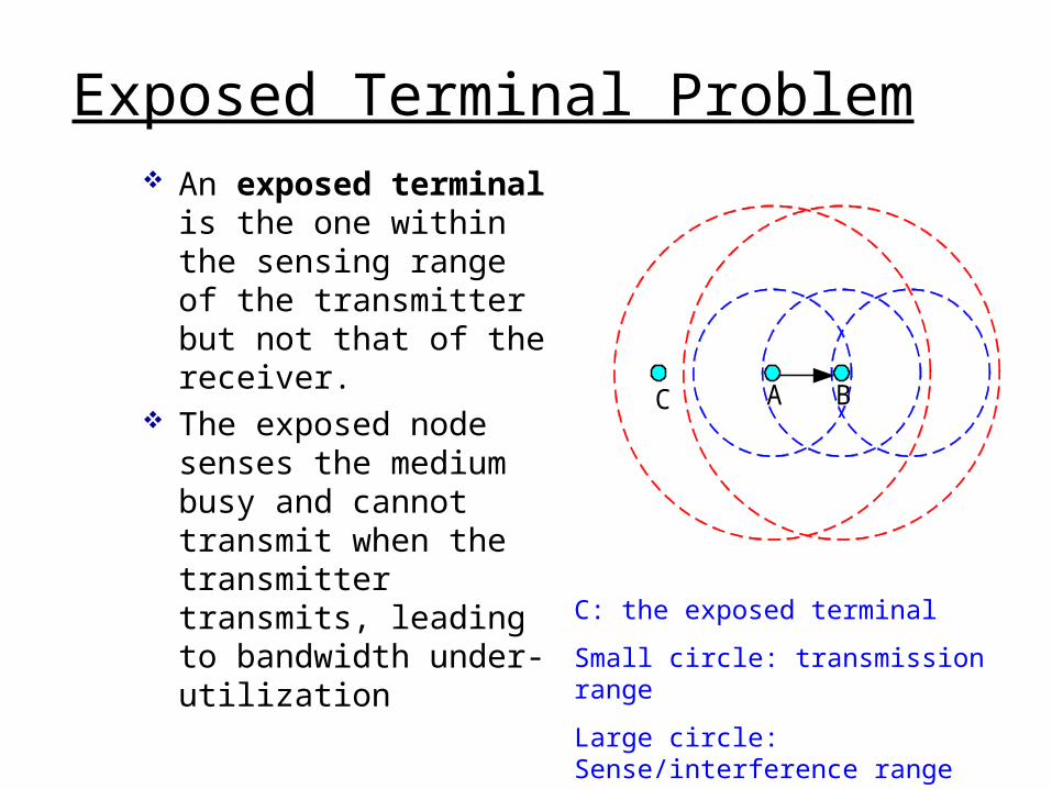
Exposed Terminal Problem An exposed terminal is the one within the sensing range of the transmitter but not that of the receiver.
The exposed node senses the medium busy and cannot transmit when the transmitter transmits, leading to bandwidth under-utilization
A BC
C: the exposed terminal
Small circle: transmission range
Large circle: Sense/interference range
Wireless, Mobile Networks 6-38
framecontrol
durationaddress
1address
2address
4address
3payload CRC
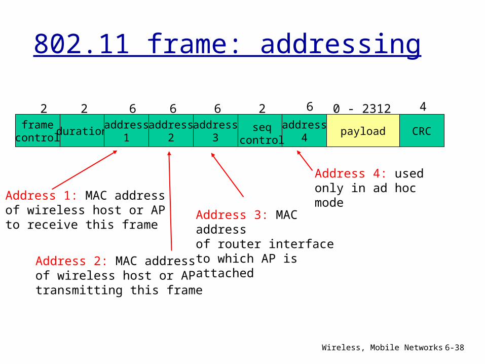
2 2 6 6 6 2 6 0 - 2312 4
seqcontrol
802.11 frame: addressing
Address 2: MAC addressof wireless host or AP transmitting this frame
Address 1: MAC addressof wireless host or AP to receive this frame
Address 3: MAC addressof router interface to which AP is attached
Address 4: used only in ad hoc mode
Wireless, Mobile Networks 6-39
Internetrouter
AP
H1 R1
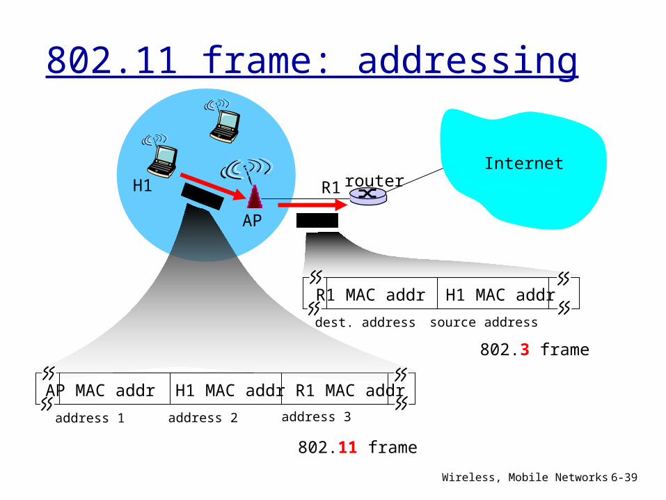
AP MAC addr H1 MAC addr R1 MAC addr
address 1 address 2 address 3
802.11 frame
R1 MAC addr H1 MAC addr
dest. address source address
802.3 frame
802.11 frame: addressing
Wireless, Mobile Networks 6-40
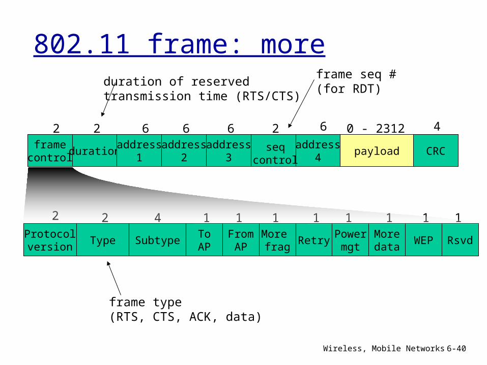
framecontrol
durationaddress
1address
2address
4address
3payload CRC
2 2 6 6 6 2 6 0 - 2312 4
seqcontrol
TypeFromAP
SubtypeToAP
More frag
WEPMoredata
Powermgt
Retry RsvdProtocolversion
2 2 4 1 1 1 1 1 11 1
802.11 frame: moreduration of reserved transmission time (RTS/CTS)
frame seq #(for RDT)
frame type(RTS, CTS, ACK, data)
Wireless, Mobile Networks 6-41
hub or switch
AP 2
AP 1
H1 BBS 2
BBS 1
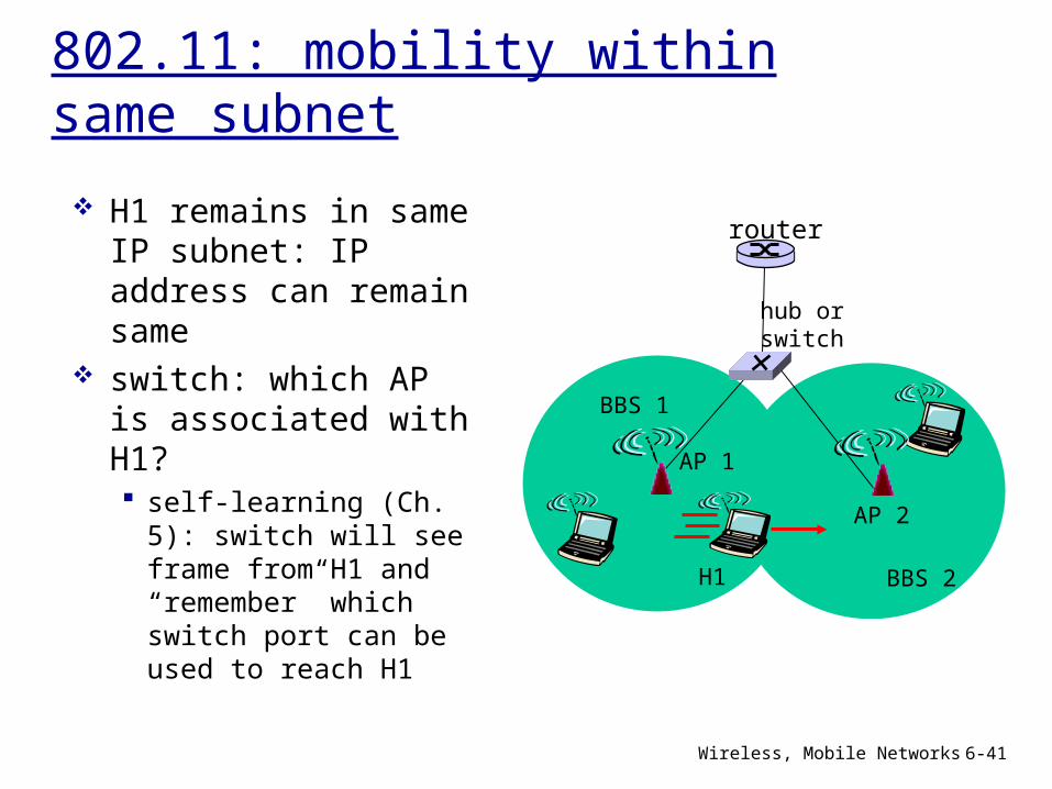
802.11: mobility within same subnet
router H1 remains in same IP subnet: IP address can remain same
switch: which AP is associated with H1? self-learning (Ch. 5): switch will see frame from H1 and “remember” which switch port can be used to reach H1
Wireless, Mobile Networks 6-42
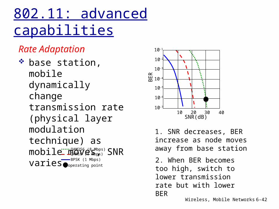
802.11: advanced capabilitiesRate Adaptation base station, mobile dynamically change transmission rate (physical layer modulation technique) as mobile moves, SNR varies
QAM256 (8 Mbps)QAM16 (4 Mbps)
BPSK (1 Mbps)
10 20 30 40SNR(dB)
BE
R
10-1
10-2
10-3
10-5
10-6
10-7
10-4
operating point
1. SNR decreases, BER increase as node moves away from base station
2. When BER becomes too high, switch to lower transmission rate but with lower BER
Wireless, Mobile Networks 6-43
802.11: advanced capabilitiesPower Management node-to-AP: “I am going to sleep until next beacon frame” AP knows not to transmit frames to this node
node wakes up before next beacon frame
beacon frame: contains list of mobiles with AP-to-mobile frames waiting to be sent node will stay awake if AP-to-mobile frames to be sent; otherwise sleep again until next beacon frame