Embed Size (px)
Citation preview
Wireless Mini Loggers LR8512, LR8513, LR8514, and LR8515
1
HIOKI Technical Notes Vol. 2 2016 No. 1
Data can be downloaded both during and after measurement. Since data is not segmented even when downloaded during measurement, data from ongoing measurement can be checked whenever the user desires.
B. Power-Saving Function for Long Battery LifeDevices equipped with wireless functionality tend to use
batteries quickly due to high power consumption, not only while communicating, but also in standby mode.
To avoid this potential pitfall, Hioki equipped these products with functionality for activating Bluetooth wireless technology only during preset times as defined by a power-saving schedule. Shorter wireless utilization times translate into longer battery life, and battery-powered operating time can approach about 3.5 months when wireless functionality is turned off (LR8514 with a recording interval of 1 min.; reference value at 23°C [73.4°F]).
The schedule can be set in terms of dates, days of the week, and times.
C. Ability to Download Data to a Tablet or ComputerNo dedicated device is needed in order to download data
from the products, which can send data to an Android tablet, Android smartphone, or Windows computer.
When the Bluetooth wireless function is turned on, the ease with which a third party can establish a communications
Abstract—The Wireless Mini Loggers LR8512, LR8513, LR8514, and LR8515 can send data from a remote location to tablet or computer wirelessly, without complex configuration. This paper describes the features, architecture, and other characteristics of these products.
I. IntroductIon
The LR8512, LR8513, LR8514, and LR8515 enable measurement data to be checked wirelessly from a remote location. Consequently, they enable voltage and current to be measured safely even when positioned inside a distribution panel or control panel since the panel’s cover can be left closed as no wires need to be routed outside the panel. Similarly, they make it possible to check data such as temperature and humidity inside a clean room from outside the room. In this way, these products allow data from high locations or locations from which it would be difficult to establish a wired connection, for example from a moving piece of equipment, to be checked from a safe location.
Furthermore, the LR8512, LR8513, LR8514, and LR8515 can be used as measurement units for the Wireless Logging Station LR8410, making it possible to use them to implement real-time measurement with the LR8410 or to place them in the field to collect data on their own, as merited by the characteristics of the particular application at hand.
II. overvIew
The LR8512, LR8513, LR8514, and LR8515 are compact, two-channel loggers that incorporate Bluetooth wireless technology. This product line consists of four models for pulse (LR8512), load and leakage current (LR8513), temperature and humidity (LR8514), and voltage and thermocouple (LR8515) measurement.
At the same time, Hioki has developed software for downloading data to Android handsets and Windows computers.
III. Features and FunctIons
A. Ability to Collect Data From Remote Locations WirelesslyThe products incorporate Bluetooth wireless technology,
enabling data recorded by the logger to be downloaded to a tablet or computer in a remote location.
Wireless Mini Loggers LR8512, LR8513, LR8514, and LR8515
Takayuki KurashimaEngineering Division 1, Engineering Department
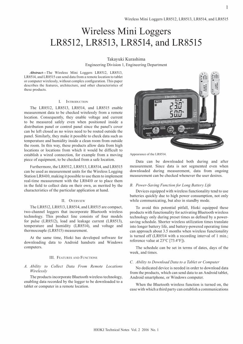
Appearance of the LR8514.

Wireless Mini Loggers LR8512, LR8513, LR8514, and LR8515
2
HIOKI Technical Notes Vol. 2 2016 No. 1
connection is undesirable from a security point of view. The products address this issue with a password authentication function. Control is only accepted via communications with terminals whose legitimacy has been authenticated with a password. All device control instructions via communications from terminals that have not been so authenticated are ignored.
D. Four Models From Which to Choose, Depending on the ApplicationFollowing are descriptions of each of the four application-
specific models:
1) Wireless Pulse Logger LR8512: The LR8512 can record pulse integrated values, frequency of rotation, and logic ON/OFF signals. For example, it can be used to measure signals such as pulse output from a flow meter and record daily fluctuations.
2) Wireless Clamp Logger LR8513: With the addition of an optional clamp current sensor, the LR8513 can perform AC/DC load current, AC leakage current, and simple power measurement. If the voltage value and power factor value are set in advance, it can perform simple power calculations, generating results for a 1-phase/2-wire circuit that can be read directly on the instrument.
This model also offers an average value recording mode that records the average of values measured at a sampling
speed of up to 0.5 seconds, making it easy to ascertain demand at a 30-minute interval.
3) Wireless Humidity Logger LR8514: With the addition of an optional temperature and humidity sensor, the LR8514 can measure temperature and humidity, providing a simple solution for recording and managing those environmental characteristics.
The ability to connect two sensors with different cable lengths to the instrument is useful in applications where it is necessary to compare temperature and humidity readings inside and outside a given piece of equipment, for example.
4) Wireless Voltage/Temp Logger LR8515: The LR8515 can measure DC voltage and temperature using a thermocouple (K or T). Users can select from several voltage ranges (±50 mV f.s., ±500 mV f.s., ±5 V f.s., and ±50 V f.s.), enabling this single instrument to measure voltages ranging from minuscule signals from actinometers or heat flow sensors to battery voltages.
Since voltage and thermocouple settings can be set for each channel, it is possible to view the correlation between voltage and temperature using a single instrument.
Iv. archItecture
A. Hardware ArchitectureFig. 1 provides a block diagram for the LR8512 as
a representative model of the series. A 16-bit one-chip
Measurement section
Bluetoothcontrollermodule
LCDCPU
Switch× 3
Flash ROM(32 Mibit†)
FRAM(16 Kibit†)
Low-passfilter
Low-passfilter
Attenuator Comparator
Attenuator
Counter
Counter
CH1+CH1-
Input
Powercircuit
3.3 VAC adapteror
External power
LR alkaline batteries(AA size) × 2
Switch
Measurement3.3 V
Powercircuit
Measurement5 V
3.3 V
Switch
CH2+CH2-
Comparator
Lithium battery (Clock backup)
Crystaloscillator
Fig. 1. LR8512 measurement circuitry and overall block diagram.
Wireless Mini Loggers LR8512, LR8513, LR8514, and LR8515
3
HIOKI Technical Notes Vol. 2 2016 No. 1
microcontroller is used to control all device circuitry, performing functionality including measurement circuit control, LCD display, key entry control, and Bluetooth wireless control. Although each model has different measurement and power supply circuitry, all models use a shared circuit architecture for other control.
The communications interface uses a Bluetooth wireless module, enabling each device to communicate directly with a computer or tablet as well as with the LR8410.
Since measurement data is stored in a 32-Mibit† flash memory module that serves as the instrument’s data memory, it is possible to record data for extended periods of time. Furthermore, data is backed up in the event of a reduction in the battery voltage.
The instruments use a three-way power supply that enables them to operate using an AC adapter, dry-cell batteries, or an external power source, allowing users to choose the power mode that best suits their application. In addition, the instruments are designed to save power by shutting down the measurement power supply while measurement is not being performed and the Bluetooth wireless module when wireless communication capability is not needed. This design serves to extend the amount of time the instrument can be used while operating on battery power.
B. Measurement Circuit Architecture1) LR8512 measurement circuit: The LR8512 can
accept mechanical input from relays, switches, and similar components as well as pulse voltage input of up to 50 V DC. In addition, the comparator’s threshold voltage is user-configurable, allowing the circuit to be switched between two detection levels.
Furthermore, the circuit incorporates two low-pass filters (for preventing chatter) whose filter time constant can be switched between settings for mechanical contact input and electronic contact input. When using mechanical contacts with a switch, relay, or similar component, the chatter prevention filter can be switched on to reduce input signal chatter.
By using the microcontroller’s built-in counter to count pulses, it is possible to integrate pulses (to obtain total and cumulative counts) and to measure frequency of rotation. In addition, on/off logic signal measurement can be selected.
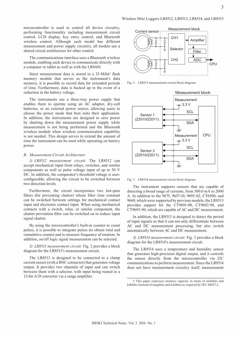
2) LR8513 measurement circuit: Fig. 2 provides a block diagram for the LR8513’s measurement circuit.
The LR8513 is designed to be connected to a clamp current sensor (with a BNC connector) that generates voltage output. It provides two channels of input and can switch between them with a selector, with input being routed to a 12-bit A/D converter via a range amplifier.
The instrument supports sensors that are capable of detecting a broad range of currents, from 500.0 mA to 2000 A. In addition to the 9675, 9657-10, 9695-02, CT6500, and 9669, which were supported by previous models, the LR8513 provides support for the CT9691-90, CT9692-90, and CT9693-90, which are capable of AC and DC measurement.
In addition, the LR8513 is designed to detect the period of input signals so that it can not only differentiate between AC and DC measurement processing, but also switch automatically between AC and DC measurement.
3) LR8514 measurement circuit: Fig. 3 provides a block diagram for the LR8514’s measurement circuit.
The LR8514 uses a temperature and humidity sensor that generates high-precision digital output, and it controls the sensor directly from the microcontroller via I2C communications to perform measurement. Since the LR8514 does not have measurement circuitry itself, measurement
Selector
CH2
CH1 Amplifier
Filter
ADCCPU
Measurement blockCurrent sensor
Fig. 2. LR8513 measurement circuit block diagram.
Sensor 1(Z2010/Z2011)
CPU
Measurement3.3 V
Measurement block
SCL
SDA
Sensor 2(Z2010/Z2011)
SCL
SDA
Measurement3.3 V
Fig. 3. LR8514 measurement circuit block diagram.
† This paper expresses memory capacity in terms of mebibits and kibibits (instead of megabits and kilobits) as required by IEC 60027-2.

Wireless Mini Loggers LR8512, LR8513, LR8514, and LR8515
4
HIOKI Technical Notes Vol. 2 2016 No. 1
By relying on a database, the app can extract and display settings based on the screen layout. In addition, settings can be easily ordered and displayed in list form.
3) Measurement control: The app can control the measurement state of the connected logger. It also provides a monitor function that lets users check the logger’s latest measured values in either numeral or graph form.
In the past, it was necessary to start measurement in order to check measured values. However, starting measurement caused previously captured measurement data to be erased. Since the monitor function does not save any data, even after measurement is started, it is possible to check measured values while retaining previously measured data.
4) Downloading and exporting data: Data can be downloaded whenever the user desires. In addition, the app checks data from each measurement against a uniquely assigned measurement ID and automatically creates and links data from each download session.
accuracy for temperature and humidity depends solely on the sensor.
4) LR8515 measurement circuit: Fig. 4 provides a block diagram for the LR8515’s measurement circuit.
The LR8515 can perform voltage measurement and temperature measurement using a thermocouple (K or T). It uses a switching method to switch between input channels with a relay and provides isolation between the channels.
After input selection, the signal is amplified and then measured by the microcontroller’s built-in ΔΣ A/D converter. The LR8515 also incorporates a digital temperature sensor near the connector on the printed circuit board, which it uses to measure the connector temperature and correct the reference junction temperature during thermocouple measurement.
v. soFtware
A. Wireless Logger Collector for AndroidWireless Logger Collector for Android is a data
downloading app for Android handsets. Its design envisions users who make the rounds of a number of scattered loggers to collect data for later use.
Hioki’s design goal was to deliver an intuitive user experience by means of a simple user interface. Up to 100 loggers can be registered, selected, and controlled.
Fig. 5 illustrates an example of a screenshot.
1) Data transmission: Wireless Logger Collector for Android is compatible with an Android handset with Bluetooth wireless technology to send and receive data to and from loggers. Since wireless communications processing is multithreaded, users can enjoy lag-free operation even when handling large volumes of data.
2) Settings information: SQLite, a relational database that is included in Android as a standard library, is used to manage logger settings data. The app is able to deliver rational, high-speed processing thanks to embedded storage access.
+
-CH1 input
+
-CH2 input Attenuator
Burnoutdetection
circuit
CH switches Attenuator switches Amplifier
Thermometer(RJC)
CPU
ADC
Fig. 4. LR8515 measurement circuit block diagram.
Fig. 5. Wireless logger collector for Android screenshot.

Wireless Mini Loggers LR8512, LR8513, LR8514, and LR8515
5
HIOKI Technical Notes Vol. 2 2016 No. 1
To protect the integrity of data that has been downloaded and saved by the software, data is stored in a dedicated region of the device that can be used only by the Android app. To enable that data to be accessed from outside the host device, data can be exported to external media or to an Android region that is externally accessible. Once it has been exported, data can be easily accessed from a computer by connecting the Android handset to the computer with a USB cable.
Since data is saved in a file format that is compatible with the Logger Utility, a computer application designed for use with Hioki loggers, waveforms can be checked later on a computer.
B. Wireless Logger Collector for PCWireless Logger Collector for PC is a data downloading
application for Windows computers.
For maximum legibility and operability, Wireless Logger Collector for PC uses a list display and large buttons like most email software. Up to 100 loggers can be registered, selected, and controlled.
Fig. 6 illustrates an example of a screenshot.
1) Settings information: The application uses a general-purpose database to manage logger settings information.
Using a database not only eliminates the need to build a proprietary format, but also makes it possible to combine and extract only the necessary information. By means of this capability, users can easily reorder various parameters displayed in list form on the screen.
2) Sending data: There are two ways to send and receive data using Bluetooth wireless technology on Windows: serial communications using a virtual COM port and Winsock, a method that is similar to that used in Ethernet communications. Wireless Logger Collector for PC supports both of these communications methods.
Computers without Bluetooth wireless technology can be equipped to perform Bluetooth communications by connecting a Bluetooth adapter to a USB port. Numerous manufacturers offer proprietary drivers for these products, and some of those drivers only support virtual COM port communications.
The standard Windows Bluetooth driver supports Winsock communications and also provides the device search and pairing functionality needed in order to use Bluetooth wireless technology for data communications.
3) Multi-threaded communications: The Bluetooth standard supports simultaneous communications with up to seven devices. Because it can control up to 100 loggers, Wireless Logger Collector for PC would incur a significant time penalty if it attempted to recover data by connecting to one instrument at a time. To address this issue, the application uses multiple communications threads to
connect to up to seven loggers simultaneously and download data from independently.
Once a given thread’s downloading operation completes, it immediately connects to a logger with data waiting to be downloaded, reducing overall download times.
4) Downloading data: Users can specify when data is downloaded. In addition, it is possible to configure the application to download data automatically without user action by setting a regular downloading interval (from 10 minutes to 1 day).
Each measurement is assigned a unique measurement ID. By comparing each measurement ID with the measurement IDs of previously downloaded data, the application can determine whether the data is part of an existing measurement or a new measurement. If the application determines that a given piece of data is a continuation of an existing measurement, it adds that measurement data to the previously downloaded data. If it determines that the data is new, it creates a new data file and registers the creation information in the database.
5) Exporting data: Downloaded data is saved in a format that is compatible with the Logger Utility. Consequently, data can be immediately displayed in the Logger Utility by launching it directly from the Wireless Logger Collector for PC.
Functionality for combining and exporting multiple pieces of measurement data can be used to view data acquired from multiple loggers under different measurement conditions on a single, unified time axis.
vI. archItecture
A. LR8512, LR8513, LR8514, and LR8515To achieve the product’s core design concept of
miniaturization, Hioki developed a structure that minimizes dead space. Specifically, this design places the batteries at the top of the back of the logger and the external power supply input at the bottom on the left side. The LR8512 and LR8514 have their inputs on the right side, while the LR8513 and LR8515 have theirs on the bottom. To standardize
Fig. 6. Wireless logger collector for PC screenshot.

Wireless Mini Loggers LR8512, LR8513, LR8514, and LR8515
6
HIOKI Technical Notes Vol. 2 2016 No. 1
operability across multiple models, all devices use the same lower case, battery cover, and control panel design.
To keep the batteries from falling out if the instrument is subjected to a strong mechanical shock during measurement, the battery cover is secured firmly in place by four fasteners and one screw, as shown in Fig. 7.
B. Z2010 and Z2011To reduce sensor malfunctions caused by condensation,
water droplets, and other foreign material, the air vents on the Humidity Sensor Z2010 and Z2011 used by the LR8514 are located near the sensor and on the bottom of the enclosure rather than throughout the entire enclosure (see Fig. 8).
The position and size of the air vents have been optimized in order to minimize the amount of time until the sensor resumes normal operation in the event that it malfunctions due to the accumulation of water droplets on its surface.
vII. conclusIon
By making it possible to download data remotely, these products expand the field of measurement applications, for example by eliminating the need for personnel to be present in hazardous or inaccessible locations during measurement. Going forward, Hioki expects increases in the speed and range of wireless communications to further expand these applications and to accelerate the shortening and streamlining of work times.
Shuhei Takeda*1, Shinji Nishimura*1, Atsushi Hayama*1, Yuki Shioiri*1, Chiharu Saito*2, Makoto Muto*3
regIstered trademarks
• Bluetooth is a registered trademark of Bluetooth SIG, Inc. (USA). The trademark is used by Hioki E.E. Corporation under license.
• Microsoft and Windows are either registered trademarks or trademarks of Microsoft Corporation in the United States and other countries.
• Android is a registered trademark of Google, Inc.
Fig. 7. Battery cover.
Fig. 8. Z2010 mechanism.
*1 Engineering Division 1, Engineering Department*2 Engineering Division 5, Engineering Department*3 Engineering Division 10, Engineering Department