Embed Size (px)
Citation preview

Wireless Matrix Corporation Document MBUD-0086v1b 12369-B Sunrise Valley Drive, Reston, VA 20191 Version 1.0b Phone : (703) 262-0500 March 4, 2004 FAX : (703) 262-0380 www.wirelessmatrixcorp.com
Wireless Matrix MBS2 User Guide

Wireless Matrix MBS2 User Guide Document MBUD-0086v1b
MBS2 User Guide Copyright © 2004 Wireless Matrix Corporation. All rights reserved. Printed in the United States of America This document is proprietary to Wireless Matrix Corporation. Do not reproduce, use or disclose without permission. We have made every effort to ensure the accuracy of all information contained in this document. However, Wireless Matrix Corporation makes no expressed or implied warranty or representation based upon the enclosed information. Revision History: Version 0.5 2/03/04 Initial Draft Version 0.9 3/01/04 Final Draft Version 1.0b 3/04/04 Initial Version
March 04, 2004 Page 2

Wireless Matrix MBS2 User Guide Document MBUD-0086v1b
MBS2 User Guide TABLE OF CONTENTS
INTRODUCTION............................................................................................................. 4 TECHNICAL SUPPORT .................................................................................................................................. 4 REGULATORY STATEMENTS........................................................................................................................ 4 OTHER SAFETY PRECAUTIONS .................................................................................................................... 5
GENERAL DESCRIPTION............................................................................................ 6 MBS2 UNIT ................................................................................................................................................ 6 WAW NETWORK ........................................................................................................................................ 7
COMPONENTS................................................................................................................ 8 COMMAND SERVER ..................................................................................................................................... 8 SATELLITE MODEM ..................................................................................................................................... 9 GPRS MODEM ............................................................................................................................................ 9 802.11B MODEM ......................................................................................................................................... 9 GPS RECEIVER............................................................................................................................................ 9 KEYFOB RECEIVER.................................................................................................................................... 10
FEATURES ..................................................................................................................... 10 MULTI-NETWORK ROUTING...................................................................................................................... 10 ACTIVE NETWORK (AN) DETERMINATION ............................................................................................... 10 MAGIC PACKET ......................................................................................................................................... 10 IN-YARD ACCESS ...................................................................................................................................... 10 WIRELESS DHCP (WDHCP) .................................................................................................................... 11 INTERNET PROTOCOLS SUPPORT ............................................................................................................... 12 USER APPLICATIONS ................................................................................................................................. 12 ALERT AND PERSONAL ALERT .................................................................................................................. 12
MISCELLANEOUS ....................................................................................................... 12 ADDRESSING ............................................................................................................................................. 12 THROUGHPUT............................................................................................................................................ 12 TOOLS ....................................................................................................................................................... 13
INSTALLATION OVERVIEW .................................................................................... 13 INSTALLATION .......................................................................................................................................... 13 MBS2 OPERATION.................................................................................................................................... 14 EQUIPMENT FAILURE OR DAMAGE............................................................................................................ 14
March 04, 2004 Page 3

Wireless Matrix MBS2 User Guide Document MBUD-0086v1b
MBS2 User Guide
INTRODUCTION This guide explains procedures for using the Wireless Matrix Mobile Base Station 2 (MBS2) modem as installed on a vehicle for data communications.
Technical Support Technical questions should be directed to the Customer Care team at (866) 456-7522.
Regulatory Statements The following regulatory approvals apply for the Mobile Base Station 2 (MBS2):
• FCC
• IC
• PTCRB
FCC Part 15 Compliance This device complies with Part 15 of the FCC Rules. Operation is subject to the following two conditions:
1. This device may not cause harmful interference 2. This device must accept any interference received, including interference that may cause
undesired operation. Modifications not expressly approved by Wireless Matrix USA, Inc. could void the user's authority to operate the equipment.
NOTE: This equipment has been tested and found to comply with the limits for a Class B digital device, pursuant to Part 15 of the FCC Rules. These limits are designed to provide reasonable protection against harmful interference in a residential installation. This equipment generates, uses and can radiate radio frequency energy and, if not installed and used in accordance with the instructions, may cause harmful interference to radio communications. However, there is no guarantee that interference will not occur in a particular installation. If this equipment does cause harmful interference to radio or television reception, which can be determined by turning the equipment off and on, the user is encouraged to try to correct the interference by one or more of the following measures:
• Reorient or relocate the receiving antenna. • Increase the separation between the equipment and receiver. • Connect the equipment into an outlet on a circuit different from that to
which the receiver is connected. • Consult the dealer or an experienced radio/TV technician for help.
March 04, 2004 Page 4

Wireless Matrix MBS2 User Guide Document MBUD-0086v1b
The MBS2 satellite radio emits radio frequency (RF) energy when transmitting. The MBS2 must be installed in a manner that provides a minimum separation distance of 20 cm or more between the antenna and persons to satisfy FCC RF exposure requirements for mobile transmitting devices. Operators should maintain a safe distance from radio when transmitting. Wireless Matrix recommends installing the MBS2 device with a safe distance of 51 cm or more. The safe distance of 51 cm is measured from the center of the antenna beam with respect to the FCC OET Bulletin 65, Edition 97 01 “Evaluating Compliance With FCC Guidelines for human Exposure to Radiofrequency Electromagnetic Fields”. The 51 cm distance should be maintained under the following conditions:
• The antenna is powered on and transmitting. The MBS2 transmits only when the computer in the vehicle sends messages to the host computer.
• A person is blocking line-of-sight to the satellite during transmission. A person on or above the vehicle roof and within 51 cm of the unit could interfere with the MBS2 transmission path.
Other Safety Precautions Read and understand the complete Installation Guide, including the Safety Precautions, prior to using the MBS2 Modem. The MBS2 is a radio unit used to receive and transmit data. When in operation, the MBS2 transmits and receives RF signals to and from a Geo-stationary orbital satellite. The MBS2 must be used in accordance with the safety guidelines stated in this document. Failure to comply could result in physical harm and can be a hazard to the health of the operator of this unit.
WARNING! The following safety precautions must be observed during all phases of the operation, usage, service or repair of the MBS2 unit.
1. The MBS2 must be operated at the voltages described in the unit technical documentation.
2. The MBS2 must not be mechanically or electrically changed or modified. Use of all connectors should follow the guidance of the MBS2 technical documentation.
3. Replace fuse with same type and rating for protection against fire and damage.
4. The MBS2 is a RF generating device. Do not operate the unit when anyone is in the vicinity noted in the Safety Information section of this guide. This could result in personal injury.
5. Do NOT operate the MBS2 unit in areas where explosives are in use as the RF frequency could interfere with the operation, causing hazardous conditions. Do NOT operate the MBS2 unit in areas where two-way radio communications is prohibited.
6. Use discretion when determining the MBS2 installation point. After installation, ensure that all systems are functioning properly. Consult vehicle dealer for further information.
March 04, 2004 Page 5

Wireless Matrix MBS2 User Guide Document MBUD-0086v1b
GENERAL DESCRIPTION
MBS2 Unit The MBS2 is comprised of an Interactive Satellite Packet Data (ISPD) modem, a General Packet Radio Service (GPRS) terrestrial wireless modem, and an 802.11b modem, well as associated antennas. It also supports a Global Positioning Service (GPS) receiver, as well as a Keyfob receiver for Personal Alert. The MBS2 is pictured in Figure 1 and Figure 2.
Figure 1: MBS2 Front View with Covering
March 04, 2004 Page 6

Wireless Matrix MBS2 User Guide Document MBUD-0086v1b
Figure 2: MBS2 Front Oblique View without Covering
The MBS2 is typically connected to a peripheral computer called the Client Side Computer (CSC) using a tethered serial port connection and/or an untethered 802.11b connection. The CSC can be a standard laptop or other computing device. The user application and associated middleware resides on the CSC. The MBS2 is capable of supporting some user applications. The CSC communicates over the Wireless Matrix Wide Area Wireless (WAW) Network via the MBS2. At the link layer, PPP or the Modem Interface Protocol (MIP) can be used between the CSC and MBS2. At the transport layer, the CSC can use UDP to communicate with a Customer Host via the WAW Network.
WAW Network The WAW Network, shown in Figure 3, consists of a Data Hub, satellite and terrestrial wireless networks, and the MBS2 unit. WAW is an enterprise solution wireless data service between remote modems and Customer Host computers, offering seamless coverage with a single point of connection to the network. This packet-data service can be routed over either Mobile Satellite Venture’s MSAT-2 satellite or the AT&T Wireless Services (AWS) GPRS network Customer Hosts connect to the Data Hub via Frame, VPN, or leased-line. The Data Hub consists of:
• Network Operations Support System (NOSS): manages the modems on the WAW network
• Wireless IP Gateway (WIPG) that connects to the ISPD and AWS GPRS networks and controls data sent between the Customer Hosts and MBS2s.
• ISPD equipment The Wireless Matrix-owned and operated ISPD Network consists:
• Primary Data Hub equipment located at Wireless Matrix in Reston, Virginia • Secondary Data Hub equipment located in Ashburn, Virginia • Communications Ground Segment (CGS) located at Mobile Satellite Ventures in Reston,
Virginia • MSAT-2 geostationary satellite. MSAT-2 covers the United States and its coastal waters
as well as Canada On the client side, a CSC device connects to the MBS2. The MBS2 routes messages over the Wireless Matrix ISPD Satellite network or the AWS GPRS network, depending on which network the MBS2 determines to be the “Active Network”. The MBS2 is also responsible for notifying the WIPG when its Active Network changes.
March 04, 2004 Page 7

Wireless Matrix MBS2 User Guide Document MBUD-0086v1b
Wireless MatrixWide Area Wireless (WAW)
Wireless MatrixData Hub Network Components
Mobile SatelliteVentures (MSV)
AT&TFrame Relay
Location/NetworkRegister
WirelessIP Gateway
(WIPG)
Network OperationsSupprt System (NOSS)
ISPDProcessors
MSV-Reston
MSAT-1,2X.25
MBS-2
802.11b
CSCFrame Relay
Internet
Leased Line
Hosts
Hosts
Hosts
AT&T WirelessServices (AWS)
GPRS
Figure 3: WAW Network
COMPONENTS
Command Server The MBS2 command server is a logical entity that contains information about routing, MBS2 status, and configuration parameters. It has a dedicated port number that can be accessed by external entities to make configuration changes to and queries about the status of the MBS2 and wireless network availability. The command server is accessible by Customer Hosts, client applications, CSCs, and the WAW Network Operational Support System (NOSS) by using UDP. Some of the key features of the command server are as follows:
• Initiate the MBS2 commissioning process • Send and receive MBS2 Management messages to and from the NOSS • Provide control of and access to information about the various components within the
MBS2 (GPS, Terrestrial and Satellite modems, etc.) • Monitor status of MBS2 and its components, and provide status information to the NOSS
or CSC upon request
March 04, 2004 Page 8

Wireless Matrix MBS2 User Guide Document MBUD-0086v1b
Satellite Modem The L-band satellite modem is used to communicate at L-band via the ISPD network. The modem is provided with an omni-directional cross-dipole antenna. The satellite modem is designed and manufactured by Wireless Matrix.
GPRS Modem A GPRS terrestrial wireless modem is used to communicate on the AT&T Wireless Services (AWS) GPRS network. The GPRS modem is a Motorola model G20 OEM module. A monopole antenna is used with this modem.
802.11b Modem The MBS2 uses a 802.11b WLAN modem to connect to the CSC wirelessly. By doing so, it extends the range of a CSC user to several hundred feet from the MBS2. This “Wireless Tether” also provides good in-building penetration, up to 150 feet. The Wireless Tether supports all of the same functionality that a standard serial port connection supports. The MBS2 is capable of routing the communications of multiple CSCs via the WAW. Also, a CSC using one MBS2 may “Roam” to another MBS2 and use the latter to communicate with the WAW network. With this flexible scheme, the MBS2 is truly a Base Station that is mobile. The MBS2 uses the Cisco Aironet 350 PCMCIA card for 802.11b communications. An elevated dipole antenna is provided. The customer is responsible for providing the CSC with a wireless modem card capable of communicating with the Wireless Tether modem and approved by Wireless Matrix. MBS2 supports ad-hoc mode for communications with a CSC, or infrastructure mode for communications with an Access Point in an In-Yard Communications situation. The MBS2 also has the capability to use the Wireless Tether to communicate with CSCs that use a sleep mode for power conservation. See the Magic Packet section for details.
GPS Receiver The GPS receiver option includes a GPS receiver and a separate patch antenna. The GPS receiver is a Lassen LP, manufactured by Trimble. It measures position with an accuracy of 25 meters1, velocity accurate to 0.1 meters/sec, and time accurate to 95 nano-seconds. The GPS information can be used by the Wireless Matrix AVL application, the application running on the CSC, or another User Application stored on the MBS2. The CSC application can access GPS information through command server primitives (refer to Fehler! Verweisquelle konnte nicht gefunden werden. for details).
1 Subject to Selective Availability (SA)
March 04, 2004 Page 9

Wireless Matrix MBS2 User Guide Document MBUD-0086v1b
Keyfob Receiver For Alert and Personal Alert features, the MBS2 uses a 315 MHz keyfob receiver and inverted-F antenna. An external keyfob transmitter is also provided. FEATURES
Multi-Network Routing The Multi-Network Routing (MNR) function enables the MBS2 to send communications over the best available network, as determined by a “Primary Network” setting and the coverage situation. The routing algorithm is based on a parameter called the “Active Network”, and is explained in the sections below. The MBS2 is configured during Commissioning to have a “Primary Network”, or a preferred network. The MBS2 will always use the Primary Network as the Active Network when within Primary Network coverage. The Secondary Network will become the Active Network only if no Primary Network coverage is available. For instance, if the Primary Network is satellite, and the MBS2 is in satellite coverage, the Active Network for the MBS2 is satellite. If the MBS2 leaves satellite coverage but is still in terrestrial wireless coverage, the Active Network would become terrestrial.
Active Network (AN) Determination The MBS2 periodically evaluates the Satellite and GPRS Network coverage and updates its Active Network based on a predefined Active Network Algorithm (not to be confused with the MNR algorithm). In general, if a change in its Active Network occurs, the MBS2 will inform the WIPG of the new Active Network value by sending an Active Network Message (ANM), so that the WIPG can use the Active Network for its own MNR algorithm.
Magic Packet WAW offers the Magic Packet (MP) feature to conserve battery life on a CSC while maintaining Wireless Tether communications upon demand. Thus, a CSC can enter sleep mode and be awaken by a Magic Packet whenever the Customer Host has data to send to the CSC (provided that the CSC is in WLAN range of the MBS2). The Magic Packet Feature is described in more detail in _________.
In-Yard Access In-yard access provides the ability to send and/or receive data with lower latency, high throughput, and reduced airtime expense by routing the data directly through a Customer-owned In-Yard 802.11 network When the MBS2 arrives in an In-Yard district, the MBS2 will associate with the AP at the district. On successful association, the CSC sends or receives traffic directly to or from the customer corporate network. As soon as the MBS2 leaves the AP WLAN coverage area, it will go back to its original configuration (i.e., WAW IP).
March 04, 2004 Page 10
Wireless Matrix MBS2 User Guide Document MBUD-0086v1b
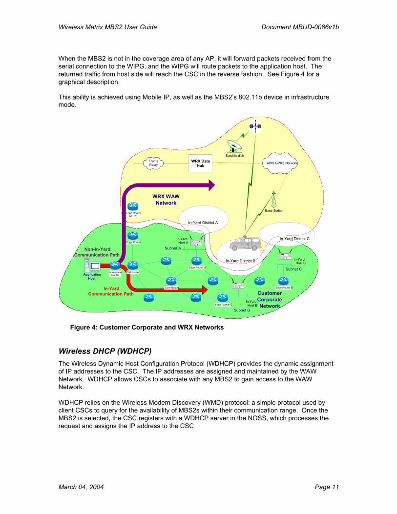
When the MBS2 is not in the coverage area of any AP, it will forward packets received from the serial connection to the WIPG, and the WIPG will route packets to the application host. The returned traffic from host side will reach the CSC in the reverse fashion. See Figure 4 for a graphical description. This ability is achieved using Mobile IP, as well as the MBS2’s 802.11b device in infrastructure mode.
WRX DataHub
Satellite dish
Base Station
AWS GPRS Network
Customer Corporate Network
In-Yard Host C
Subnet C
In-Yard District C Subnet A
In-YardHost A
In-Yard District A
In-YardHost B
Subnet B
In-Yard District B
Frame Relay
Edge Router B
WRX WAWNetwork
Non-In-Yard Communication Path
Application Host
Immediate Router
DM-Router Edge Router A
Edge Router C
Core Router
Edge Router
Edge Router (WRX)
In-YardCommunication Path
Figure 4: Customer Corporate and WRX Networks
Wireless DHCP (WDHCP) The Wireless Dynamic Host Configuration Protocol (WDHCP) provides the dynamic assignment of IP addresses to the CSC. The IP addresses are assigned and maintained by the WAW Network. WDHCP allows CSCs to associate with any MBS2 to gain access to the WAW Network. WDHCP relies on the Wireless Modem Discovery (WMD) protocol: a simple protocol used by client CSCs to query for the availability of MBS2s within their communication range. Once the MBS2 is selected, the CSC registers with a WDHCP server in the NOSS, which processes the request and assigns the IP address to the CSC
March 04, 2004 Page 11

Wireless Matrix MBS2 User Guide Document MBUD-0086v1b
Internet Protocols Support The MBS2 is capable of supporting the following IP-based protocols:
• DHCP client and server on all MBS2 IP-capable interfaces • Standard IP routing between all MBS2 IP-capable interfaces • PPP over the Serial Interface • ICMP Ping from the MBS2 to the user-specified address • Telnet and TFTP firmware downloads from all MBS2 IP-capable interfaces
User Applications The MBS2 supports multiple User Applications residing in its firmware. The User Applications can total 64kB in size. One specific type of User application is Wireless Matrix AVL.
Alert and Personal Alert The Alert and Personal Alert features can be used to inform the Customer Host of an important event, such as driver in danger or “man-down” messages. The Customer Host would be able to distinguish between a keyfob or vehicle button activation. The Alert message is generated by the closing of an electrical contact, and the Personal Alert message is generated by a keyfob. The wireless keyfob signal can be received by the MBS at a distance of 150 feet. The message is sent with location information and truck identification by using the Wireless Matrix AVL application. MISCELLANEOUS
Addressing All components of the WAW system are addressed using IP addressing. Customer Hosts, MBS2s, and CSCs are designated IP addresses in the following subnet range: 10.128.0.1 to 10.254.255.254. From the Customer Host point of view, the CSC IP address may be statically assigned or dynamically assigned using WDHCP. The pool of addresses used for assignment shall be specified by either the Customer or Wireless Matrix personnel. Ports 51000 to 51999 shall be reserved for User Applications residing on the MBS2.
Throughput MBS2 throughput on the WAW network is almost entirely dependent on the throughput of the underlying ISPD and GPRS networks. Raw data rates are known, but actual throughputs are estimated, based on the fact that multiple users share the over-the-air channels. Table 1 lists the data rate information for each network.
March 04, 2004 Page 12

Wireless Matrix MBS2 User Guide Document MBUD-0086v1b
Type of Data Rate ISPD AWS GPRS Raw 6.75 kbps 42.8 to 64.2 kbps After Overhead, channel sharing (Estimated) 0.3 to 0.6 kbps 4 to 8 kbps
Table 1: MBS2 Underlying Networks Throughput Comparison
Note that since the underlying networks are transparent to the MBS2 user, the actual throughput depends on the current Active Network. A minimum throughput is not guaranteed.
Tools Wireless Matrix provides two tools to assist the developer on the WAW system: Wireless Matrix Chat and Communicator. The tools are Open Source license tools distributed in code form. This provides complete visibility for the developer and enables straightforward extensions to the program that the developer may want to add. The Wireless Matrix Chat program was created to provide simple chat sessions over the air from Customer Host to MBS2 or from MBS2 to MBS2. The Communicator is similar to the On-Board Computer (OBC) application used in the Wireless Matrix X.25 network. It allows an operator to:
• Edit and send messages to an arbitrary IP address
• Send a file of arbitrary size to an arbitrary IP address
• View the text of messages received by the Communicator
• Monitor the operational status of the MBS2
• Monitor the signal strengths of the networks to which the MBS2 is connected
• Access the Command Server of the MBS2
The Communicator user interface is suitable for all types of client devices, including small form factor WinCE handheld and, potentially, Palm devices. It operates on both sides of the WAW (server/host and client/MBS2), so that with a single tool the developer can easily test end-to-end communications. On the client side, the interface to the MBS2 command server is via the serial port (or wireless tether), and on the Customer Host side the interface to the MBS2 command server is over the WAW Network via standard UDP/IP. INSTALLATION OVERVIEW
Installation The Wireless Matrix MBS2 modem is mounted to a vehicle and wired in order to:
• Draw power from the vehicle to power the unit • Connect the unit to a Client Side Computer (CSC) for data transmission/receipt purposes
Installation instructions for the MBS2, while not complex, are detailed, and are included in a separate installation manual (MBUD-0085v1, dated 2/27/04). Please consult this manual if you need to install the MBS2 unit.
March 04, 2004 Page 13

Wireless Matrix MBS2 User Guide Document MBUD-0086v1b
March 04, 2004 Page 14
To verify the MBS2 unit is operational; ensure the following items:
1. Move the vehicle to an area where there are no obstructions to the southern exposure for the Wireless Matrix MBS2.
2. Check the cable connections to the MBS2 and verify it is securely connected.
MBS2 Operation The operation of the MBS2 is passive. It will activate in order to send data, which is triggered by use of an application on the Client Side Computer for such purposes. It will also activate when it receives a remote request (such as when it is polled for vehicle information), or receives data (such as a message from a dispatcher). In addition, because the unit will automatically select the best routing for messages without user intervention, the user does not need to interact with the unit to select a communications method. In this regard, there is no activity which the vehicle operator must undertake with the MBS2 unit.
Equipment Failure or Damage If the MBS2 unit suffers a mechanical failure or is damaged during the course of the program, please notify Customer Care as soon as possible. Equipment that is returned damaged or in non-working order without prior notification will be the responsibility of the program participant.