Embed Size (px)
Citation preview
Technical Guide
FEATURE OVERVIEW AND CONFIGURATION GUIDE
Wireless Manager
IntroductionWireless Manager is a software module that provides AlliedWare Plus switches with the capability to manage the TQ series of Allied Telesis Wireless Access Points (APs). Wireless Manager enables an Allied Telesis switch to become a single point of management for operation, administration, and maintenance of all TQ series access points in the Enterprise wireless network. Key Wireless Manager features include:
RF management and controlAbility to continuously monitor the wireless transmission coverage from access points and dynamically reconfigure their radios to minimize interference and improve performance. Load balancing can be applied automatically in order to evenly distribute clients among their available APs.
Enterprise class securityWireless Manager and its controlled access points are WPA2 (IEEE 802.11i) capable. WPA2 is an advanced set of security features that satisfies the policy requirements for both large scale industrial and residential networks. WPA2-Enterprise provides a centralized security model that incorporates RADIUS for managing authentication and inter-operates with the IEEE 802.1x framework, supporting multiple Extended AP (EAP) modes.
End-to-end Quality of ServiceAbility to apply QoS across the entire wireless LAN to optimize resource use on an application by application basis. Wireless Manager is also able to prioritize each application based on its requirements for bandwidth, latency, and jitter.
alliedtelesis.com xC613-22065-00 REV A
Introduction
ContentsIntroduction............................................................................................................................................................................. 1
Product Support................................................................................................................................................................... 3
Wireless Networks Introduction ................................................................................................................................ 4
Access Points (APs)................................................................................................................................................... 4
Wireless network entities and components ............................................................................................... 4
Network names................................................................................................................................................ 6
AP Profiles............................................................................................................................................................ 6
AP Database Registration ........................................................................................................................... 7
AP Discovery...................................................................................................................................................... 7
Radio frequency management............................................................................................................................. 8
Wireless Manager Configuration Concepts....................................................................................................... 11
Wireless Manager Configuration Example......................................................................................................... 13
Overview...................................................................................................................................................................... 13
Physical Network ..................................................................................................................................................... 16
Terrestrial to wireless network configuration.......................................................................................... 18
Access security .......................................................................................................................................................... 19
Wireless network .................................................................................................................................................... 20
Configurable radio options ................................................................................................................................ 22
Configure the optional radio settings ................................................................................................ 22
Managing wireless channel plans .......................................................................................................... 26
Tutorial configuration............................................................................................................................................. 28
Configure the AP databases ................................................................................................................... 28
Configure the RADIUS and AAA functions .................................................................................. 29
Configure DHCP........................................................................................................................................... 30
Configure the network VLANs............................................................................................................. 32
Configure the switch interface ports ................................................................................................. 33
Configure the country code ................................................................................................................... 34
Configure the VLAN wireless associations .................................................................................... 35
Configure the AP wireless profiles...................................................................................................... 37
Show Running Configuration Output ................................................................................................................... 40
Configuring different profiles on the same AP type...................................................................................... 43
Loading a new software image to a TQ Series AP....................................................................................... 45
Load the image file using TFTP ............................................................................................................. 45
Network Example - Constraints and Enhancements................................................................................... 47
Security settings ........................................................................................................................................................ 47
Access at desired network mode/speed.................................................................................................... 47
Configuration overview of enhanced network............................................................................ 49
Aspects and Issues of WiFi Transmission............................................................................................................ 52
Modulation coding scheme................................................................................................................................ 52
Managing traffic, and collision avoidance .................................................................................................... 54
RTS/CTS dialogue......................................................................................................................................... 54
Page 2 | Wireless Manager

Introduction
RTS/CTS and the hidden node problem.........................................................................................54
Collisions caused by wireless interference......................................................................................55
Detecting collisions by using show output commands............................................................55
Wireless Terminology Glossary ................................................................................................................................56
Wireless Manager | Page 3

Product Support
Product Support
Products: AT-SBx8100 with a CFC960 controller card
AT-SBx908
AT-x930
Licensing Wireless Manager operation requires a Feature License. Consult your Allied Telesis reseller for more information.
Capacity The following table shows the maximum number of Access Points (APs) supported by each switch type:
Table 1: AP Locations and configuration details
The following table shows Wireless Manager capacity recommendations and limitations:
Table 2: AP Recommendations and limitations
FurtherInformation
For more information on the commands used, refer to the Wireless Manager chapter of your switch's Command Reference, found on our website at alliedtelesis.com.
Wireless Manager CapacityAT-SBx8100
(CFC 960) AT-SBx908 AT-x930
20 APs supported Yes Yes Yes
40 APs supported Yes No Yes
80 APs supported Yes No No
120 APs supported Yes No No
Feature Recommendations and Limitations
Max APs 120 (limited by AW+ License)
Max clients per AP 200 (recommended: 30)
Max AP profiles 255
Max local MAC authentication 1000
Page 4 | Wireless Manager

Wireless Networks Introduction
Wireless Networks Introduction
Access Points (APs)
The WiFi networks described in this guide comprise a number of wireless connected users who gain access to the resources of a corporate network via one or more Wireless Access Points (APs). Examples in this section are based on the AT-TQ4600 and AT-TQ4400 APs, as shown in the figure “AT-TQ Series access point” shown below. Note that when this guide refers to a network by name, i.e. Employee or Guest, it is referring to the network entity known as an SSID. For more information on SSIDs, see "Network names" on page 7.
Figure 1: AT-TQ Series access point
The transmission systems that operate to the IEEE 802.11 series of standards are becoming increasingly complex. For example, the illustration above shows an AT-TQ4600 AP. This AP contains two radios, where each radio is allocated three antennas. Each antenna is able to deliver two simultaneous signals. With 3 antennas per radio this offers the possibility of delivering six simultaneous signals per radio transmission. This is accomplished using a processes such as MiMo and spatial streaming.
For more information on this topic, see "Radio frequency management" on page 9.
Wireless network entities and components
Wireless networks that contain an Access Point (AP) operate in what is known as Infrastructure Mode. Where APs connect to a wired backbone this portion of the network is referred to as the Distribution System (DS).
Wireless devices connect to an AP using one of a number of available wireless radio bands. Within each band, wireless devices sending data to an AP must contest for the shared wireless capacity in a similar way to devices that share a common wired LAN cable. In a single AP network operating within the same radio channel this contention domain is known as a Basic Service Set (BSS). Internally, the BSS is identified by its Basic Service Set ID (BSSID).
Radio 1adi
Radio 2AP AT-TQ4600
Wireless Manager | Page 5

Wireless Networks Introduction
For a single AP network this ID is the AP’s MAC address. At the protocol level, wireless devices “attach” themselves to a specific AP. They can do this either passively or pro-actively.
Passive connection involves a wireless station listening to “beacon frames” (Hellos) transmitted by each AP and requesting attachment to the AP of their selection—usually chosen on the basis of signal strength.
Pro-active connection involves the wireless station sending a “probe” message to the AP, then choosing which AP to attach to from the responses received.
A single physical AP can comprise many logical (Virtual) Access Points (VAPs). Each VAP appears to the user as a separate AP with its own BSSID (virtual MAC address). By default, each radio on a TQ4600 AP can have up to 16 VAPs assigned to it. Each Virtual MAC address is assigned by starting with the AP’s physical MAC address and incrementing by one to produce 32 virtual MAC addresses. Each radio on the AP is assigned 16 addresses from this address pool.
Page 6 | Wireless Manager

Wireless Networks Introduction
Network names
At the user level, each user network is assigned a Network Name of up to 32 characters. Internally these names are defined by a 32 binary character Service Set ID (SSID). The network name is the entity that client users select when they log into a wireless network.
In a single Service Set network (one AP with no VAP support) the BSSID and the SSID would—although they have different formats—both identify the same set of networked devices. However, in most networks the same SSID would identify the networked devices within a selected group of Basic Service Sets. That is, the same SSID is often defined on multiple VAPs that reside either on the same physical AP or across several physical APs. For these “Extended” networking environments, the letter E is often prefixed to some of the WiFi terms. For example, Extended SSID becomes ESSID, and Extended BSS becomes EBSS.
However, to avoid complication, the E prefix is not made visible to users in the Wireless Manager show output screens. The network example presented in this chapter has two SSIDs “Guest” and “Employee”. Both these entities could be defined as ESSIDs because they are common to four APs each containing these two VAPs.
Note that each network can be mapped to a specific VLAN on the wired network—Distribution System (DS)—in order to carry its traffic to and to and from its wireless network. This mapping also enables servers attached to the DS to carry out functions such as security and verification applications on behalf of each individual wireless network:
AP Profiles
An AP profile is a named set of wireless AP configuration settings. Once created, a named profile can then be applied—template style—to a specific group of APs. Typically a profile would contain the following configuration entities:
Network names (SSIDs)
Network name to VLAN mapping
VAP Configuration
Radio Configuration (allocated channels etc)
Wireless Configuration, e.g. setting RTS/CTS, setting frame fragmentation size, etc.
Security levels, WPA2, WEP etc.
RADIUS application and aspects of its configuration
Figure 4 on page 13 illustrates—in principle—a generic AP wireless profile.
The AP group to which a given profile is to be applied can be selected as comprising all TQs of a particular type or can be selected by TQ type and MAC address. The tutorial network example shown in this guide applies wireless profiles solely by their TQ type, TQ4600 and TQ4400. However, there may be times where you want to apply different profiles to APs of the same type. The section "Configuring different profiles on the same AP type" on page 44 shows a possible example of this requirement.
Wireless Manager | Page 7

Wireless Networks Introduction
AP Database Registration
One of the early steps in configuring Wireless Manager is to manually register (validate) the MAC addresses and location details of your APs into the Wireless Manager AP database.
To register APs into the AP database you use the ap database command from the Global Config mode. The section "Configure the AP databases" on page 29 shows how this is done for the tutorial network example.
Once you have registered your APs, you can see a list of all currently validated APs together with their locations and status by running the show wireless ap database command.
AP Discovery
There could be situations where the manual entry process is incomplete. For example, a new AP could be physically connected but not registered to the database. To manage these situations, Wireless Manager has two discovery methods for detecting unvalidated APs (i.e. those not registered in the AP database).
Layer 2 VLAN Discovery
Layer 3 IP Discovery
By default both discovery methods are enabled, but you can use the command discovery method, from the Global Config mode, to specifically enable or disable either method. The operation of these two methods are explained below.
Layer 2VLAN
Discovery
Layer 2 VLAN discovery is used where the Wireless Manager and its connected APs are located in the same layer 2 multicast domain. Wireless Manager periodically sends a multicast frame containing a discovery message on each VLAN enabled for discovery. You can enable the discovery protocol on up to 16 VLANs. VLANS are enabled for AP discovery by using the discovery vlan-list command. Each AP responds to a discovery frame by returning its MAC address and location. Wireless Manager checks these returned MAC addresses against those validated to its AP database. Note that Wireless Manager does not validate unlisted MAC addresses, but instead stores them for display from the show wireless ap failure status command. The output from this command lists unvalidated AP MAC addresses and adds the description, “No Database Entry.” If you decide a particular unlisted AP is valid for registration, you simply add it using the process described earlier in this section.
At this point it is worth clarifying the various VLAN configurations that can operate with L2 discovery. There are several VLAN options that can be applied, but there are some basic rules to follow.
By default, VLAN 1 is both the default VLAN on TQ Series APs, and is also the VLAN enabled for Layer 2 Discovery. On the Wireless Manager switch ports, VLAN 1 is the default VLAN; so if you configure VLAN 1 as the discovery VLAN on the WM switch ports, this should work. However, there could be reasons why you might want to chose another VLAN for L2 discovery. If so, here are some points to remember:
APs will only recognise discovery frames if they are on their discovery VLAN (VLAN 1 by default). Note that to change discovery to another VLAN requires direct access to the AP. It cannot be done using Wireless Manager.
Page 8 | Wireless Manager

Wireless Networks Introduction
APs will recognise discovery frames that arrive untagged.
In our tutorial network example we have set VLAN 30 as the admin VLAN and also use this for L2 discovery. We also decided that changing the discovery VLAN to 30 on our APs would add an unnecessary level of management complexity. Considering these factors, this was our preferred option for the tutorial network example:
Leave the APs with their defaults (VLAN1 as both the default VLAN and the one used for L2 discovery).
Configure WM to have VLAN 30 as the management VLAN and also the one used forL2 discovery.
Configure all WM ports that connect to APs to be untagged members of VLAN 30. Thusall management traffic will (internally) enter WM’s AP ports tagged for VLAN 30, but willleave (destined for their APs) untagged. See the line “switchport trunk native vlan 30” inthe section "Configure the switch interface ports" on page 34.
Layer 3 IPDiscovery
Layer 3 IP discovery can be used where APs are located on different subnets. To implement L3 discovery you add a list of IP addresses for APs that are known to exist. WM then sends association invitations to all IP addresses listed. If the AP returns an “invitation accepted” message, then WM adds the AP’s details so that it can be manually registered to the AP database as a validated AP. To add a list of IP discovery addresses you use the discovery ip-list command, from the config-wireless mode.
Radio frequency management
APs are allowed to operate within a fixed band of allocated frequencies and power levels. The range of channels that an AP may use is determined by its 802.11 operating mode. Each AP within the AT-TQ Series is able to operate using the following standardized transmission modes:
Table 3: IEEE 801.11 operating modes
MODE/STANDARD OPERATION
IEEE 802.11a Defines transmissions in the 5 GHz U-NII band
Uses Orthogonal Frequency Division Multiplexing (OFDM)
Supports data rates from 6 Mbps to 54 Mbps
IEEE 802.11b/g Defines transmissions in the 2.4 GHz ISM band
Enhances the earlier 802.11 standard to include support for transmission speeds of5.5 Mbps and 11 Mbps
Uses Spread Spectrum (DSSS) or Frequency Hopping, Spread Spectrum (FHSS)
Uses Complementary Code Keying (CCK) to provide the higher data rates. of 1Mbps to 11 Mbps
IEEE 802.11g extends speeds to up to 54 Mbps
Employs Orthogonal Frequency Division Multiplexing (OFDM)
Supports data rates ranging from 1 to 54 Mbps
Wireless Manager | Page 9

Wireless Networks Introduction
Note: Interference can result if multiple access points within range of each other are broadcasting on the same or overlapping channels. For the b/g radio band, the classical set of non-interfering channels is 1, 6, and 11. Figure 2 below shows the 2.4 GHz frequency band, with channels 1, 6 and 11 depicted with bold outlines.
Figure 2: Wireless Channels in the 2.4 GHz Band
Figure 3 below shows the 5 GHz frequency band, with channels shaded. Note that there is no overlap between channels in this frequency band. However, because some channels
IEEE 802.11a/n Defines transmissions in the 5 GHz ISM band and includes support for both 802.11a and 802.11n devices
IEEE 802.11n is an extension of the 802.11 standard that includes enhancements such as Multiple-Input Multiple-Output (MIMO) technology
Supports data rates of up to 248 Mbps and nearly twice the indoor range of 802.11 b, 802.11g, and 802.11a.
IEEE 802.11b/g/n Defines transmissions in the 2.4 GHz ISM band
Includes support for 802.11b, 802.11g, and 802.11n devices
5 GHz IEEE 802.11n The recommended mode for 5 GHz 802.11n networks where 802.11a or 802.11b/g support is not required.
Provides higher throughput where 802.11a or 802.11b/g legacy support is not employed.
2.4 GHz IEEE 802.11n The recommended mode for networks with 802.11n devices that operate in the 2.4 GHz frequency band where 802.11a or 802.11b/g legacy support is not required
Provides higher throughput where 802.11a or 802.11b/g legacy support is not employed.
802.11a/n/ac The recommended mode for networks with 802.11ac IEEE 802.1
Provides higher throughput where 802.11a or 802.11b/g legacy support is not employed.
802.11n/ac The recommended mode for 802.11 networks that operate in the 2.4 GHz frequency band without the need to support 802.11a or 802.11b/g devices
Provides higher throughput where 802.11a or 802.11b/g legacy support is not employed.
Note: The IEEE 802.11n standard prohibits static and dynamic WEP security modes.Additionally, 802.11n requires the WPA cypher to be CCMP(AES).
Table 3: IEEE 801.11 operating modes (continued)
MODE/STANDARD OPERATION (CONTINUED)
122.467
12.412
22 MHz
ChannelCenter Frequency(GHz)
22.417
32.422
42.427
52.432
62.437
72.442
82.447
92.452
102.457
112.462
132.472
142.484
Page 10 | Wireless Manager

Wireless Networks Introduction
within this band are also used by aviation radar, Dynamic Frequency Selection (DFS) is mandatory in these channels. The channels on which DFS must be applied is determined on a national basis by each country’s regulatory body. DFS operates by the AP listening for radar signals operating on each channel it is using. If an AP radio detects a radar signal on one of its transmitting channels, it must move its transmission to an alternative channel, in order to give priority to the radar signal. DFS requirements and their operating frequency bands is determined by National Regulations. Setting your TQ AP to individual national requirements is a one of the functions carried out by Wireless Manager’s country code command.
Figure 3: Wireless channels in the 5.0 GHz band
525.260
565.280
605.300
645.320
100,104,108,112,1165.500 - 5.580
132,136,1405.660 - 5.700
149,153,157,161,1655.745 - 5.825
365.180
405.200
445.220
485.240
Certain frequencies within this band require DFS, as defined by each country’s national regulations.
ChannelCenter Frequency(GHz)
Wireless Manager | Page 11

Wireless Manager Configuration Concepts
Wireless Manager Configuration ConceptsBefore progressing to look at an example of Wireless Manager configuration, this guide presents an overview of the elements within a Wireless Manager configuration.
The configuration process and the examples shown in this guide assume that a wireless site survey has been carried out and also that a wireless site plan and network design has been prepared. Defining these tasks and documents is outside the scope of this guide.
The main elements in configuring Wireless Manager are:
TerrestrialNetwork
Configure the following aspects of the terrestrial network—known as the Distribution System (DS):
Create and configure the VLANS. See "Configure the network VLANs" on page 33.Note that if you are not using VLAN 1 on your wireless network, you should remove the AP discovery process from VLAN 1—its default—and configure another management VLAN to receive discovery frames, as shown in the example on page 36.
Assign a VLAN to carry the multicast discovery frames. Note that this may mean removing this function from VLAN1, the default VLAN for carrying discovery frames.
Assign the Wireless Manager IP address.
Configure the interface ports used on the DS. For more information, see "Configure the switch interface ports" on page 34 and "Terrestrial to wireless network configuration" on page 19.
CountryCode
Set the country code. You should do this at an early stage in the configuration to ensure that the wireless network—Wireless Manager and its managed APs—operate to the legal regulations for wireless transmission within your country. See "Configure the country code" on page 35. Also many of the channel frequency configurations will not take effect if they are applied to disallowed channels. Note that you must reboot the switch for the applied country code to take effect.
WirelessNetworks
Configure the following wireless network entities. See "Configure the VLAN wireless associations" on page 36 for more information:
Create each of the wireless networks required.
Create the SSID for each network.
Create a mapping between each of the wireless networks, defined by their SSIDs, and the terrestrial VLAN networks with which they are respectively associated.
Set the security mode for each network.
Configure the RADIUS server group that will be used to authenticate clients attaching to the network.
Configure the radio settings within each AP profile.
See "Wireless network" on page 21, "Configure the VLAN wireless associations" on page 36 and "Wireless network entities and components" on page 5 for more information.
Page 12 | Wireless Manager

Wireless Manager Configuration Concepts
AP Profiles Configure the AP profiles for the devices used. See "Configure the AP wireless profiles" on page 38 for more information.
The major components of a generic AP profile configuration process are illustrated in Figure 4 below.
Figure 4: Generic AP profile configuration process
Note: You must run the command wireless ap reset mac to apply any configuration changes made to an AP. This command is run from the Privileged Exec mode and can take the parameter All to apply it to all APs in the managed network.
AP Database Add the details of each AP into the AP database. This information contains each AP’s MAC address and location. See "Configure the AP databases" on page 29.
RadioSettings
Configure the optional radio settings or accept their defaults. See "Configurable radio options" on page 23 for more information.
AssociatedServices
When clients connect to the wireless network, they will almost certainly need to access services via a wired Distribution System (DS). For example, if access security is applied, they will need to access to an authentication server. Similarly, if DHCP is used to allocate IP addresses, they will need to access a DHCP server.
If you are using DHCP, create the DHCP address pools for each user type. See "Configure DHCP" on page 31 for more information.
Configure the Radius and AAA functions, where appropriate. See "Configure the RADIUS and AAA functions" on page 30.
Configure any other features or services that are accessed via the DS.
AP_config_4600-generic.eps
TQ4600
Profile 1
VAP 0 VAP 1Configured
radiosettings
Network 1
SSIDName 1
Network 2
SSIDName 2
Radio 1
VAP 0 VAP xConfigured
radiosettings
Network 1
SSIDName 1
Network y
SSIDName y
Radio 2
Generic
AP Configuration Process
AP Configured
for Profile 1
Wireless Manager | Page 13

Wireless Manager Configuration Example
Wireless Manager Configuration Example
Overview
This section shows how to configure a basic wireless network that is managed by Wireless Manager. The example network shown in 5 below, forms the basis for the configuration examples used later in this guide.
Figure 5: Wireless Manager Example Network
In this example the Wireless Manager application is running on an AT-SBx8100 switch. The configuration has four wireless APs (three AT-TQ4600 APs and one AT-TQ4400 AP). These APs connect respectively to ports 1.1.2 through to 1.1.5 on a line card module within the AT-SBx8100 switch. The CFC960 control card, also located in the AT-SBx8100, runs both the Wireless Manager application and its user database, plus the RADIUS and DHCP Server functions. However, notice that the diagram shows the RADIUS server and the DHCP server as separate devices. Either configuration is valid and in large networks the RADIUS and DHCP servers would almost certainly exist as separate devices.
The three AT-TQ4600 APs are collectively configured by assigning to them a common AP Profile (AP Profile 1). The AT-TQ4400 AP is assigned the AP Profile 2, even though there is only one AT-TQ4400 in the network. This is because a profile can only be applied to APs of the same type.
RADIUS
serverSBx8100SwitchBladex8100
CFC9601.5.x
EmployeeGuest
EmployeeGuest
Employee
Employee
AT-TQ4600
(2nd Floor)
AT-TQ4600(1st Floor)
AT-TQ4600(Mtg Rm1)
AT-TQ4400
(Mtg Rm2)
AP Profile 2
AP Profile 1
uplink Port
Port 1.1.1
Port 1.1.3
Port 1.1.2
Port 1.1.5
Radio 1ad
Radio 2AP
Radio 1ad
Radio 2AP
Radio 1ad
Radio 2AP
Radio 1ad
Radio 2AP
Port1.1.x
Physical_Network_Example.eps
Guest
Guest
Page 14 | Wireless Manager

Wireless Manager Configuration Example
The major components of the wireless profile configuration process for the example network of Figure 5 are illustrated in Figure 6 and Figure 7 below.
Figure 6: AP Configuration process for profile 1
Figure 7: AP Configuration process for profile 2
AP_config_4600-P1_Basic.eps
TQ4600
Profile 1
VAP 0 VAP 1Mode
802.11b/g/nby default
Network 100
SSIDEmployee
Network 200
SSIDGuest
Radio 1
VAP 0 VAP 1Mode
802.11/n@ 40 MHz
Network 100
SSIDEmployee
Network 200
SSIDGuest
Radio 2
AP Configuration Process
for Profile 1
AP_config_4400_Basic.eps
TQ4400
Profile 2
VAP 0 VAP 1Mode
802.11b/g/nby default
Network 100
SSIDEmployee
Network 200
SSIDGuest
Radio 1
VAP 0 VAP 1Mode
802.11/n@ 40 MHz
Network 100
SSIDEmployee
Network 200
SSIDGuest
Radio 2
AP Configuration Process
for Profile 2
Wireless Manager | Page 15

Wireless Manager Configuration Example
In the example shown, two kinds of users access the wireless network, Employee and Guest. A RADIUS server vets the authentication of Employee users and WPA2 Enterprise is applied to provide user security and encryption. No security or authentication is applied to Guest users. See "Access security" on page 20 for more information.
Individual components of this network are explained in the next sections of this guide.
Page 16 | Wireless Manager
Wireless Manager Configuration Example
Physical Network
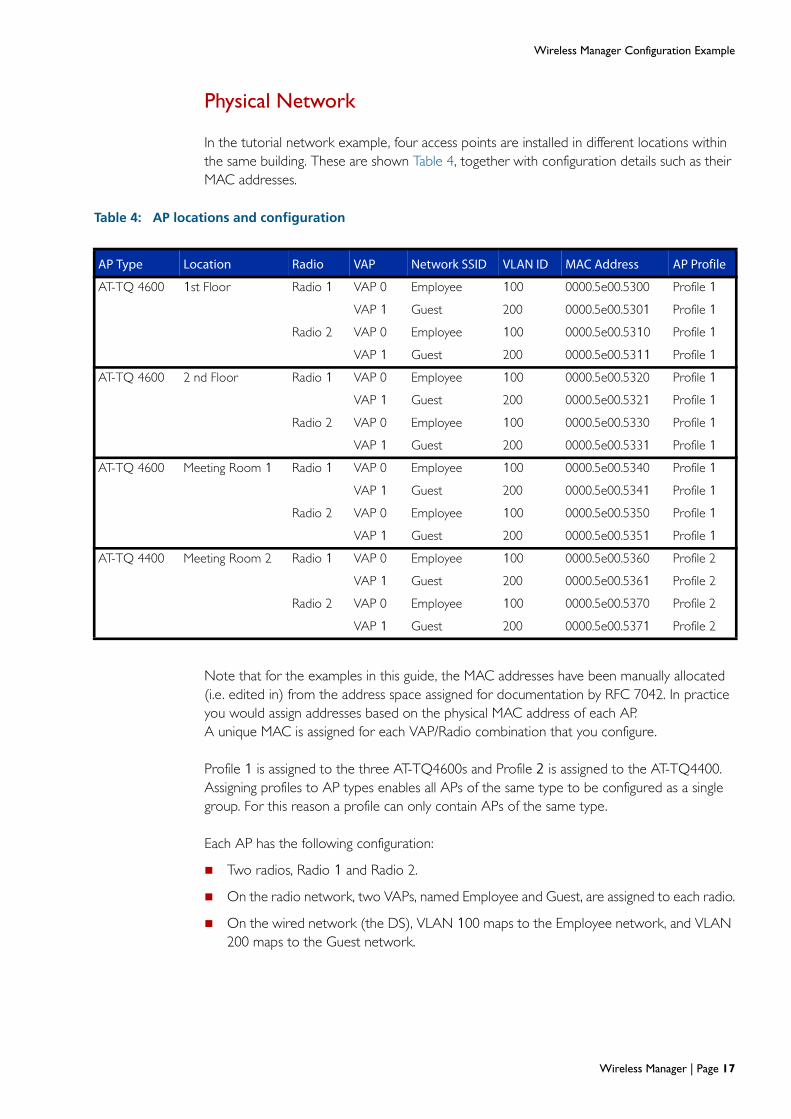
In the tutorial network example, four access points are installed in different locations within the same building. These are shown Table 4, together with configuration details such as their MAC addresses.
Table 4: AP locations and configuration
Note that for the examples in this guide, the MAC addresses have been manually allocated (i.e. edited in) from the address space assigned for documentation by RFC 7042. In practice you would assign addresses based on the physical MAC address of each AP. A unique MAC is assigned for each VAP/Radio combination that you configure.
Profile 1 is assigned to the three AT-TQ4600s and Profile 2 is assigned to the AT-TQ4400. Assigning profiles to AP types enables all APs of the same type to be configured as a single group. For this reason a profile can only contain APs of the same type.
Each AP has the following configuration:
Two radios, Radio 1 and Radio 2.
On the radio network, two VAPs, named Employee and Guest, are assigned to each radio.
On the wired network (the DS), VLAN 100 maps to the Employee network, and VLAN 200 maps to the Guest network.
AP Type Location Radio VAP Network SSID VLAN ID MAC Address AP Profile
AT-TQ 4600 1st Floor Radio 1 VAP 0 Employee 100 0000.5e00.5300 Profile 1
VAP 1 Guest 200 0000.5e00.5301 Profile 1
Radio 2 VAP 0 Employee 100 0000.5e00.5310 Profile 1
VAP 1 Guest 200 0000.5e00.5311 Profile 1
AT-TQ 4600 2 nd Floor Radio 1 VAP 0 Employee 100 0000.5e00.5320 Profile 1
VAP 1 Guest 200 0000.5e00.5321 Profile 1
Radio 2 VAP 0 Employee 100 0000.5e00.5330 Profile 1
VAP 1 Guest 200 0000.5e00.5331 Profile 1
AT-TQ 4600 Meeting Room 1 Radio 1 VAP 0 Employee 100 0000.5e00.5340 Profile 1
VAP 1 Guest 200 0000.5e00.5341 Profile 1
Radio 2 VAP 0 Employee 100 0000.5e00.5350 Profile 1
VAP 1 Guest 200 0000.5e00.5351 Profile 1
AT-TQ 4400 Meeting Room 2 Radio 1 VAP 0 Employee 100 0000.5e00.5360 Profile 2
VAP 1 Guest 200 0000.5e00.5361 Profile 2
Radio 2 VAP 0 Employee 100 0000.5e00.5370 Profile 2
VAP 1 Guest 200 0000.5e00.5371 Profile 2
Wireless Manager | Page 17
Wireless Manager Configuration Example
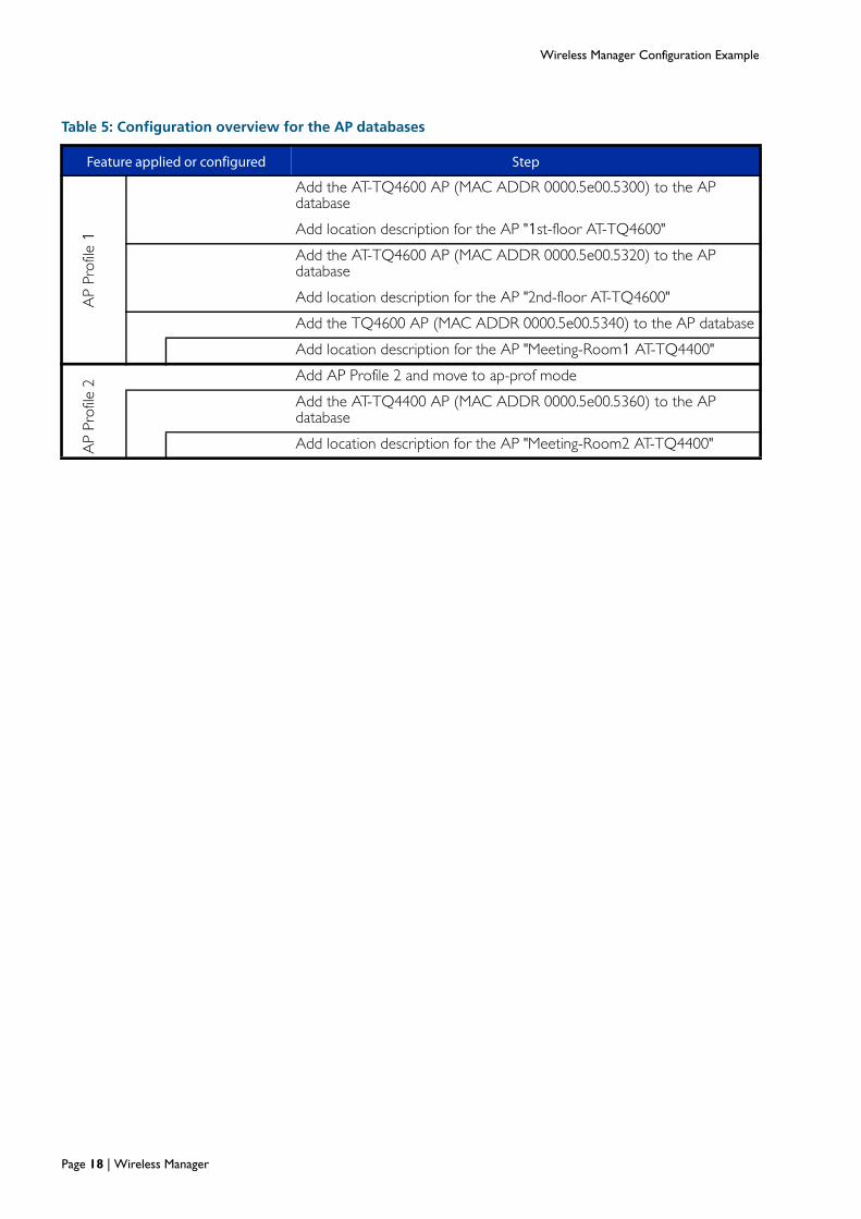
Table 5: Configuration overview for the AP databases
Feature applied or configured Step
AP
Prof
ile 1
Add the AT-TQ4600 AP (MAC ADDR 0000.5e00.5300) to the AP database
Add location description for the AP "1st-floor AT-TQ4600"
Add the AT-TQ4600 AP (MAC ADDR 0000.5e00.5320) to the AP database
Add location description for the AP "2nd-floor AT-TQ4600"
Add the TQ4600 AP (MAC ADDR 0000.5e00.5340) to the AP database
Add location description for the AP "Meeting-Room1 AT-TQ4400"
AP
Prof
ile 2
Add AP Profile 2 and move to ap-prof mode
Add the AT-TQ4400 AP (MAC ADDR 0000.5e00.5360) to the AP database
Add location description for the AP "Meeting-Room2 AT-TQ4400"
Page 18 | Wireless Manager

Wireless Manager Configuration Example
Terrestrial to wireless network configuration
The terrestrial portion of the network that interconnects the APs is known as the Distribution System (DS). In this example the DS contains the following three networks: Network 100 carries the traffic to and from the wireless network named "Employee". Network 200 carries the traffic to and from the wireless network named "Guest", and Network 30 carries the APs’ administration traffic. The mapping of networks to VLANs is shown below:
VLAN 100 mapped to Network 100—transports Employee traffic across the wired network. Network 100 is the network, defined within Wireless Manager that carries the wireless traffic whose SSID (network name) is Employee.
VLAN 200 mapped to Network 200—transports Guest traffic across the wired network. Network 200 is the network, defined within Wireless Manager that carries the wireless traffic whose SSID (network name) is Guest.
VLAN 30—transports network administration traffic across the wired network. Note that there is no VAN to Network mapping for this VLAN because administration traffic does not appear on the wireless networks.
The following table shows how the basic wireless components are configured and how the wireless networks relate to their associated VLANs on the DS. It shows, in principle, the steps used to configure these VLANS.
Table 6: Configuration overview of the DS and its relationship to the wireless components
Feature applied or configured Step
Enable the Wireless Manager.
VLA
N
1
Remove VLAN 1 as a VLAN capable of sending L2 multicast discovery frames.
VLA
N
30
Add VLAN 30 to the VLANs capable of sending L2 multicast discovery frames.
Configure the IP address of Wireless Manager as 192.168.30.254.
Net
wor
k 10
0
Enter the network config mode for Network 100.
SSID
Em
ploy
ee
Configure the Employee SSID.
VLA
N 1
00
Configure VLAN 100 as the VLAN in the wired network that transports traffic to and from wireless clients attached to wireless network 100
WPA
Sec
urity
Configure encryption to wpa-enterprise.
Set the security mode to be WPA2.
Enab
leRA
DIU
S Set the group of RADIUS servers to which to send authentication requests to be the group 'radius'
Net
wor
k 20
0 Enter the network config mode for Network 200.
SSID
Gue
st
Configure the Guest SSID.
VLA
N
200
Configure VLAN 200 as the VLAN in the wired network that transports traffic to and from wireless clients attached to wireless network 200.
Wireless Manager | Page 19

Wireless Manager Configuration Example
The network is configured to accept two user types: Employee and Guest. Guest users are assigned to the SSID named “Guest”, which is mapped to VLAN 200. This network has no authentication or security levels applied to it. Guest users can access resources subject to their VLAN access and any user passwords applied by the network’s resources and applications. Employee users are assigned the SSID name “Employee”.
Note that—technically—both the Guest and Employee networks (SSIDs) are Extended SSIDs (ESSIDs), because their existence is shared across all the APs in the wireless network.
Access security
The level of wireless access security that you apply will depend on the nature of your business and the sensitivity of the data accessed by your users. Network manager and its associated APs provide you with the following range of access security options, listed in the order of the degree of protection each provides:
None
Static-WEP
WEP-Dot1x
WPA Personal
WPA Enterprise
The network example in this guide shows two user types: Guest users, who have no access security applied, and Employee users, who have the highest security level, WPA Enterprise, applied. Although a discussion on assigning access security levels is outside the scope of this guide, as a general principle, we recommend that you do not apply the default setting of None, and that you apply at least WPA Personal access security to all users. Corporate users are advised to use WPA Enterprise. To see how access security is applied on the tutorial network example, go to "Configure the VLAN wireless associations" on page 36.
Note: The IEEE 802.11n standard prohibits static WEP and dynamic WEP (IEEE 802.1X) security modes. If APs on your network use a profile that includes the 802.11n radio mode, do not configure the profile with networks that use static or dynamic WEP as the security mode.
Page 20 | Wireless Manager

Wireless Manager Configuration Example
Wireless network
This section explains the wireless portion of the example configuration. Table 7 on page 22 shows how, in principle, a profile can be used to configure wireless networks and their radios. The general steps outlined in this table match with the specific configuration steps shown in the section, "Tutorial configuration" on page 29. A single profile is created for each AP type (an AT-TQ4600 in this example). This AP contains two separately configured radios, Radio 1 and Radio 2.
An AT-TQ4600 AP can contain up to 32 VAPs. These VAPs are apportioned 16 per radio. Each VAP can be thought of as a separate wireless Access Point; so although VAP 0 and VAP 1 exist on the same physical radio, their transmissions are separate from a user’s perspective. This is very similar to the separation that is applied by VLANs on a terrestrial network. When users scan all the wireless networks that are potentially available, they will see each VAP as a separately named network.
Table 7 on page 22, shows how each of the blocks labeled VAP 0 and VAP 1 has a direct mapping to networks 100 and 200 respectively. Table 6 on page 19, shows how each network is mapped to a specific SSID and VLAN. This mapping enables the data transmission from a user on, for example, VAP 0 to be transported to the terrestrial network as 802.1Q tagged frames carrying the VLAN tag 100. This provides seamless transmission between radio and terrestrial networks, and for AP to AP communications.
Notice that when we reach the configuration of Radio 2, the network is set for 802.11n operation. Immediately above this step is a note advising that at this point any of the other radio specific settings may also be configured, although—for brevity—only one configuration setting is made in the tutorial network example. Table 8 on page 23 shows other configurable settings that are available from the config-wireless-ap-prof-radio mode, together with a brief explanation of each setting. We strongly advise that you do not make adjustments to the radio default settings unless you fully understand their functions.
In a single AP configuration, each VAP represents a network and is assigned a network name internally known as its SSID. In the tutorial network example each AP is configured with two networks whose network names (SSIDs) are Employee and Guest. Where a configuration contains more than one AP, their networks (and their SSIDs) can be shared across the APs. How this is configured and the mapping of networks to VLANs is explained in the section "Terrestrial to wireless network configuration" on page 19.
Wireless Manager | Page 21

Wireless Manager Configuration Example
Note: At this point it is worth reviewing how you want to manage the frequencies assigned to each radio. Basically, the choice is between the following options:
manual frequency assignment by using the command radio (Wireless Manager AP mode), or
automatic frequency assignment, the default.
If you chose to have the frequencies assigned automatically, the next decision is whether to apply a channel plan. Channel plans basically determine how often Wireless Manager applies a frequency reassignment algorithm to its APs. See "Managing wireless channel plans" on page 27.
Table 7: Configuration Overview for wireless networks
Feature applied or configured Step
Profile 1 Add AP Profile 1 and move to ap-prof mode.
TQ Type Specify the AP as a TQ Type (e.g. TQ4600).
Note that at this point you can configure any of the available Radio configuration optionsBy default Radio 1 operates in the IEEE 802.11b/g/n mode.For more information see "Configurable radio options" on page 23
Radio 1 Configure the Radio 1 channel and power settingsor accept its defaults.
A
P pr
ofile
1 T
Q T
ype
set
to T
Q 4
600
R
adio
1
VAP 0 Enter the VAP config mode to configure VAP 0.
Network 100
Apply network 100 to VAP 0.
VAP 1 Enter the VAP config mode to configure VAP 1
Enable VAP 1 (VAP 0 is enabled by default).
Network 200
Configure Network 200 to VAP1.
Radio 2 Configure the Radio 2 channel and power settingsor accept its defaults.
Rad
io 2
Note that at this point you can configure any of the available Radio configuration optionsFor more information see "Configurable radio options" on page 23
Dot11n Set the bandwidth for 802.11n at 40 MHz
VAP 0 Enter the VAP config mode to configure VAP 0
Network 100
Apply network 100 to VAP 0
VAP 1 Enable VAP 1 (VAP 0 is enabled by default)
Network 200
Configure Network 200 to VAP1
Page 22 | Wireless Manager

Wireless Manager Configuration Example
Configurable radio options
Each radio has a highly configurable command set. These commands provide network management staff with the capability to fine tune each radio for efficient transmission within the local operating conditions. Fine tuning these settings does require a good understanding WiFi transmission and unless you suspect that you have network issues, the defaults provided should enable your network to run with reasonably good performance. However, should you need to change any of these network settings, this section lists each setting and describes its function. Where a topic’s description is particularly lengthy or contains additional material such as a descriptive table, an expanded description is shown separately within its own side heading.
Another point to remember before fine tuning your network is that some of these settings will only affect the outgoing transmissions. Therefore, some of your revised configurations will not apply to the client devices. To what degree this applies will depend on the option being configured and the degree of negotiation that takes place between the client device and its AP. Configuring the client stations or devices is a proprietary area and is outside of the scope of this guide.
Configure the optional radio settings
Table 8: Optional Radio Settings
Radio Option Command Defaults Function
Auto power save
apsdap-prof-radio mode
Disabled This command enables the automatic power save delivery mode for a specified radio.
Beacon interval beacon-interval
100 ms Each AP broadcasts “hello” messages advising prospective users of its existence and advertises the networks it supports. Client devices can use the information in these beacon frames to login to their selected AP network.
The beacon interval is the time space between the transmission of each beacon message.
channel auto eligible
channel auto-eligible
Either all or only channels 1, 6, and 11
This command enables either one or all of the supported channels on the radio to be eligible for auto-channel selection.
channel bandwidthin dot11nmode
dot11n channel bandwidth
IEEE 802.11a/n/ac: 80 MHz(supported)11n/ac 80 MHz(supported)a/n 40 MHz(supported)Other 20 MHz
Sets the bandwidth used in the channel when operating in the IEE 802.11n mode. Options are 20 MHz or 40 MHz.By default: Radio 1 operates in the 802.11b/g/n mode in the 2.4 GHz band at 20 MHz bandwidth.Radio 2 operates in the IEEE802.11a/n mode at 5 GHz band at 40 MHz bandwidth using dual channel operation.
dtim-period dtim-period 2 beacons Beacon frames sometimes also contain DTIM (Delivery Traffic Information Map) message components that relate to client data stored in the AP’s buffers.This command sets the number of beacon frames that are transmitted between frames that contain a DTIM.
Wireless Manager | Page 23

Wireless Manager Configuration Example
fragmentation-threshold
fragmentation-threshold
2346 (no fragmentation)
The maximum MAC PDU (MPDU) size is 2346 bytes. Decreasing the fragmentation threshold will cause frames greater than the threshold to be fragmented and sent as a series of smaller frames.
Lightly loaded networks operating at the higher frequencies are unlikely to require changing the default, which is not to fragment.
However if the network is noisy (due to interference from other APs and devices such as wireless phones etc), heavily loaded, or has a high collision rate; reducing the frame size threshold can sometimes improve performance.
Note that inter-frame spacing will exist between each of the fragmented frames. This will—in itself—result in an initial decrease of network efficiency and possibly offset the intended improvement.
Finding an optimum frame size may require some experimentation on a “try and see” basis.
frame-no-ack frame-no-ack Disabled With this feature applied, the radio will not acknowledge incorrectly received frames. Changing this option should only be carried out by expert users. If incorrect frames are not acknowledged, then error recovery will need to operate at higher levels within the protocol stack.
load balance load-balance Disabled Enable load balancing. The optional utilization parameter indicates the percentage of network utilization allowed on a radio before further clients are denied. Setting this parameter to 0 disables load balancing. Enabling load balancing may be appropriate where the concentration of APs is such that several clients may be within the range of more than one AP. In this situation client access can be balanced between these APs.
max-clients max-clients 200 This command limits the maximum number of simultaneous client associations allowed on a selected radio interface. The recommended setting is 30.
MCS Index MCS Index All indices The MCS Index is a table of index values where each value represents a specific level of transmission method and complexity.
This command enables specific MCS Index values to be enabled or disabled for a specific radio.
mode mode (Wireless Manager AP Profile Radio Mode)
Radio 1(802.11b/g/n)
Radio 2(802.11a/n)
This command configures the radio transmission mode for a radio within the AP profile and Radio (1 or 2) selected.Options are: {a|bg|a-n|bg-n|n-only-a|n-only-g|a-n-ac|n-ac}.Where:(n-only-a) is 802.11n at 5 GHz (on radio 1only).(n-only-g) is 802.11n at 2.4 GHz (on radio 2only).(bg-n) is 802.11b/g/n (on radio 2only).
Table 8: Optional Radio Settings (continued)
Radio Option Command Defaults Function
Page 24 | Wireless Manager

Wireless Manager Configuration Example
multicast transmission rate
multicast tx-rate
automatic(rate = 0)
This command selects the rate at which the radio transmits the multicast frames.Options at 5 GHz are: 6, 11, 12, 18, 24, 36, 48, and 54 Mbps.Options at 2.4 GHz are: 1, 2, 5.5, 6, 9, 11, 12, 18, 24, 36, 48, and 54 Mbps.
power auto power auto Disabled Enables Wireless Manager to automatically adjust the APs’ power assignment.
power default power default 100% Configures the power setting for the selected radio. When the power auto command is enabled, it sets the initial power value; otherwise it sets a fixed power value. Both values are stated as a percentage of total power.
power minimum
power minimum
1% When the power auto command is enabled, this command applies the minimum power level that the adjustment algorithm will allow for the selected radio.
protection protection Auto (enabled) Selects whether legacy protection is applied when operating in 802.11n mode. Applying protection enables legacy APs and stations to transmit on the same radio frequency as later devices and in their legacy mode.
rate limit mode (Wireless Manager AP Profile Radio Mode)
DisabledNormal=50 pkts/secBurst= 75 pkts/sec
This command is used to enable broadcast and multicast traffic rate limiting on each radio. If no optional parameters are entered, the command enables rate limiting on the radio with the default values.
rts-threshold rts-threshold 2347 This command configures the minimum number of octets required in an MPDU (MAC Protocol Data Unit), for RTS/CTS handshaking to take place. The most common application of this setting is where a hidden node problem is suspected.
For more information on wireless RTS/CTS setting see "RTS/CTS dialogue" on page 55.
rf-scan rf-scan other-channels
Enabled auto, 60 seconds
Enable the selected radio to perform RF scanning on channels other than its operating channel. The optional auto (automatic) or fixed period (in seconds) parameter determines how often the radio leaves its operational channel to perform its scan.
rf-scan sentry rf-scan sentry Disabled on all channels
Disables the normal operation of a radio and enables dedicated RF scanning. The radio will not allow any client associations when sentry mode is enabled.
Note that RF scanning is applied per operating channel.
rf-scan duration rf-scan duration
10 ms Sets the RF scan duration for the radio. The duration indicates how long the radio will scan on a single channel.
station isolation station-isolation
Disabled This command enables the Station Isolation mode on a selected radio. When Station Isolation is enabled, the access point blocks communication between wireless clients. The access point still allows data traffic between its wireless clients and wired devices on DS, but not among wireless clients.
Table 8: Optional Radio Settings (continued)
Radio Option Command Defaults Function
Wireless Manager | Page 25

Wireless Manager Configuration Example
wireless channel-plan
wireless channel-plan
wireless channel-plan {2.4Ghz | 5Ghz} {start | abort}
This command allows you to start a new channel plan cycle for the specified frequency band or stop a currentlyrunning channel plan cycle.
Table 8: Optional Radio Settings (continued)
Radio Option Command Defaults Function
Page 26 | Wireless Manager

Wireless Manager Configuration Example
Managing wireless channel plans
When an AP boots, each of its radios scans its allocated frequency band looking for occupied channels, and from its results will select the best channel to use. However, channel availability and congestion can vary over time, and in order to deal with this situation Wireless Manager has an internal auto-channel selection algorithm that can reallocate channels to allow for variations in network congestion. A number of commands are available for managing channel selection using a scheduling process termed a channel-plan. The following table lists these commands and how they can be used to manage channel-plan operation. Because the auto-channel selection algorithm is run for each of the 2 available channel bands (2.4 GHz and 5 GHz), the operation of channel plans is applied per channel band across all APs under the control of Wireless Manager.
Table 9: Wireless Channel-Plan Settings
Command Mode Defaults Function
wireless channel plan Priv Exec Starts a new channel plan cycle for the specifiedfrequency band, or stops a channel plan cycle that is currently running.Applied to either the 2.4 GHz or the 5 GHz frequency band.
clear wireless channel plan
Priv Exec Clears all saved channel settings and reselects channels using the initial channel selection algorithm.
show wireless plan status
Displays channel plan results for a selected AP, radio, and frequency band.
channel_plan mode Wireless Config manual Configures the channel plan mode, i.e. how often the channel is to be reconfigured within a selected frequency band. Or can be set to manual initiation.
channel_plan interval Wireless Config 6 hours If the channel-plan mode is set to manual this command sets the interval between channel plan resets. Operates per band (2.4 GHz or 5 GHz).
channel-plan run-on-ap-failure
Wireless Config When enabled, a new channel plan is initiated if an AP fails.
channel-plan timeout-on-ap-failure
Wireless Config With channel-plan run-on-ap-failure set, this command determines the delay (in seconds) before running the channel plan.
channel-plan channel-change-threshold
Wireless Config Sets the minimum signal level from a neighbor to determine whether to select an alternative channel. Applied per band (2.4 GHz or 5 GHz).
channel-plan ignore-unmanaged-APs
Wireless Config Ignore signals from unmanaged APs when configuring the channel plan
channel-plan channel-threshold-adjustment
Wireless Config enabled Sets the number of dBms adjustment in the channel change threshold for every 20% reduction in AP signal power. Operates per channel (2.4 GHz or 5 GHz).
channel auto eligible AP Profile Radio
disabled Determines which channels are available for auto-channel selection, per radio, per profile. Subject to DFS requirements.
Wireless Manager | Page 27

Wireless Manager Configuration Example
channel auto AP Profile Radio
disabled Enables auto channel adjustment (eligibility) on the selected radio.The auto-channel selection algorithm can then either automatically or manually run.Implementation is controlled by the channel plan mode command,
Table 9: Wireless Channel-Plan Settings (continued)
Command Mode Defaults Function
Page 28 | Wireless Manager

Wireless Manager Configuration Example
Tutorial configuration
This section shows an example configuration of Wireless Manager installed on an AT-SBx8100 switch.
Configure the AP databases
Table 10: AP database configuration
awplus#
configure terminal
Enter Configuration mode.
awplus(config)#
wireless
Enter config-wireless mode
awplus(config-wireless)#
wireless enable
Enter config-wireless-ap mode
awplus(config-wireless-ap)#
ap database0000.5e00.5301
Register the AP to the database
awplus(config-wireless-ap)#
location 1st-Floor-TQ4600
Enter the details and location of an AP
awplus(config-wireless-ap)#
ap database0000.5e00.5320
Register the AP to the database
awplus(config-wireless-ap)#
location 2nd-Floor-TQ4600
Enter the details and location of another AP
awplus(config-wireless-ap)#
ap database0000.5e00.5340
Register the AP to the database
awplus(config-wireless-ap)#
location Meeting-Room1-TQ4600
Enter the details and location of another AP
awplus(config-wireless-ap)#
ap database0000.5e00.5360
Register the AP to the database
awplus(config-wireless-ap)#
location Meeting-Room2-TQ4400
Enter the details and location of the last AP
awplus(config-wireless-ap)#
exit
Exit to config-wireless mode
awplus(config-wireless)#
Wireless Manager | Page 29

Wireless Manager Configuration Example
Configure the RADIUS and AAA functions
The following configuration co-locates the RADIUS and AAA servers within the AT-SBx8100 CFC960 controller card. However, the diagram Figure 8 on page 31 shows these as functions existing on dedicated hardware platforms. Either method can be employed, but having a separate RADIUS server is probably more appropriate for large networks.
Table 11: RADIUS and AAA configuration
Step 1. RADIUS and AAA
awplus(config)#
radius-server host 127.0.0.1 keynaskeywmd
Set RADIUS Server IP address.Note that the address chosen is a local host address, because the RADIUS server, in this configuration, is locally hosted.
awplus(config)#
aaa authentication wireless defaultgroup radius
Enable RADIUS authentication for wireless clients under Wireless Manager application.
awplus(config)#
crypto pki trustpoint local
Set the local CA as the system trustpoint.
awplus(config)#
crypto pki enrol local
Obtain a local CA.
awplus(config)#
radius-server local
Navigate to the Local RADIUS server configuration mode
awplus(config-radsrv)#
server enable
Enable the local RADIUS server
awplus(config-radsrv)#
nas 127.0.0.1 key naskeywmd
Add a client NAS to the list of devices that can send Auth requests to the RADIUS server.
Step 2. Register the Users to the RADIUS Server
awplus(config-radsrv)#
user employee-name1 password emp-pass1
Add employee-name1 with temporary user password <emp-pass1>
awplus(config-radsrv)#
user employee-name2 password emp-pass2
Add employee-name2 with temporary user password <emp-pass2>
awplus(config-radsrv)#
user employee-name3 password emp-pass3
Add employee-name3 with temporary user password <emp-pass3>
awplus(config-radsrv)#
user employee-name4 password emp-pass4
Add employee-name4 with temporary user password <emp-pass4>
awplus(config-radsrv)#
user employee-name5 password emp-pass5
Add employee-name5 with temporary user password <emp-pass5>
Page 30 | Wireless Manager

Wireless Manager Configuration Example
Configure DHCP
Figure 8 below shows the DHCP components of the example wireless network. In this example configuration, the DHCP pool and functions are performed within the AT-SBx8100 processor module (CFC960 card). However, Figure 8 below, shows these functions as being located on dedicated hardware platforms. Either method—integrated or separate servers—can be employed, but the separate DHCP server option is probably more appropriate for large networks.
Users connecting to the guest network (SSID = Guest) are presented via VLAN 100 to the Guest DHCP pool where they are allocated an IP address from the range 192.168.200.101 to 192.168.200.250. Similarly, users connecting to the Employee network (SSID=Employee) will be presented to the Employee DHCP pool where they are allocated an IP address from the range 192.168.100.101 to 192.168.100.250. APs can also obtain a Mgmt IP address (management IP addresses) in the range 192.168.30.1 to 192.168.30.10 via VLAN 30 from the DHCP Mgmt pool.
Figure 8: DHCP Components of the Example Wireless Network
CFC9601.5.x
AP Profile 2
SSID Employee
SSID Guest
SSID Guest
SSID Employee
AP Profile 1
Employee
Guest
Guest Employee
VLAN 30VLAN 100VLAN 200 SSID EmployeeSSID Guest
192.168.200.101TO
192.168.100.250
192.168.100.101TO
192.168.100.250
192.168.30.1TO
192.168.30.10
SBx8100SwitchBladex8100
VLAN 30
Port1.1.x
TQ4600
TQ4400
DHCP_Wireless_Example1.eps
RADIUS
server
RADIUS
server
Table 12: DHCP Configuration
Step 1. Create the DHCP Employee Pool
awplus(config)#
ip dhcp pool Employee-Pool
Enter the dhcp-config mode for the Employee address pool.
awplus(dhcp-config)#
network 192.168.100.0 255.255.255.0
Configure the subnet for the Employee pool.
awplus(dhcp-config)#
range 192.168.100.101 192.168.100.250
Configure an address range for the Employee pool.
Wireless Manager | Page 31

Wireless Manager Configuration Example
awplus(dhcp-config)#
default-router 192.168.100.254
Add a default router to the Employee pool.
awplus(dhcp-config)#
subnet-mask 255.255.255.0
Set the subnet mask option for the Employee address pool.
awplus(dhcp-config)#
exit
Return to config mode.
Step 2. Create the DHCP Guest Pool
awplus(config)#
ip dhcp pool Guest-Pool
Enter the dhcp-config mode for the Guest address pool.
awplus(dhcp-config)#
network 192.168.200.0 255.255.255.0
Configure the subnet for the Guest pool.
awplus(dhcp-config)#
range 192.168.200.101 192.168.200.250
Configure an address range for the Guest pool.
awplus(dhcp-config)#
default-router 192.168.200.254
Add a default router to the Guest pool
awplus(dhcp-config)#
subnet-mask 255.255.255.0
Set the subnet mask for the Guest address pool to be 255.255.255.0
awplus(dhcp-config)#
exit
Return to config mode.
Step 3. Create the DHCP AP-Mgmt Pool
awplus(config)#
ip dhcp pool AP-Mgmt-Pool
Enter the dhcp-config mode for the AP-Mgmt address pool.
awplus(dhcp-config)#
network 192.168.30.0 255.255.255.0
Configure the subnet for the AP-Mgmt pool.
awplus(dhcp-config)#
range 192.168.30.1 192.168.30.10
Configure an address range for the AP-Mgmt pool.
awplus(dhcp-config)#
default-router 192.168.30.254
Add a default router to the AP-Mgmt pool.
awplus(dhcp-config)#
subnet-mask 255.255.255.0
Set the subnet mask option for the AP-Mgmt address pool.
awplus(dhcp-config)#
exit
Return to config mode.
awplus(config)#
Table 12: DHCP Configuration (continued)
Page 32 | Wireless Manager

Wireless Manager Configuration Example
Configure the network VLANs
Three VLANs, numbered 30, 100 and 200, are configured in the tutorial network example. For more information on the function of these VLANs see "Terrestrial to wireless network configuration" on page 19.
Table 13: VLAN configuration
Step 1. Create the network VLANs
awplus(config)#
vlan database
Enter the config-vlan mode.
awplus(config-vlan)#
vlan 30 name AP-Mgmt-Vlan
Create VLAN 30 and name it AP-Mgmt-Vlan.
awplus (config-vlan)#
vlan 100 name Employee-Vlan
Create VLAN 100 and name it Employee-Vlan.
awplus(config-vlan)#
vlan 200 name Guest-Vlan
Create VLAN 200 name Guest-Vlan.
awplus(config-vlan)#
vlan 30,100,200 state enable
Enable VLAN 30, 100 and 200.
awplus(config-vlan)#
exit
Exit from config-vlan mode to config mode.
awplus(config)#
Step 2. Configure the VLAN IP Addresses
awplus(config)#
interface vlan30
Select VLAN 30 to configure.
awplus(config-if)#
ip address 192.168.30.254/24
Set the primary IP address for VLAN 30 (AP-Mgmt-Vlan).
awplus(config-if)#
exit
Exit from config-if mode to config mode.
awplus(config)#
interface vlan100
Select VLAN 100 to configure.
awplus(config-if)#
ip address 192.168.100.254/24
Set the primary IP address for VLAN 100.(Employee-Vlan)
awplus(config-if)#
exit
Exit from config-if mode to config mode.
awplus(config)#
interface vlan200
Select VLAN 200 to configure.
awplus(config-if)#
ip address 192.168.200.254/24
Set the primary IP address for VLAN 200.(Guest-Vlan)
Wireless Manager | Page 33

Wireless Manager Configuration Example
Configure the switch interface ports
Table 14: Switch interface configuration
Step 3. Configure the switch interfaces
awplus(config)#
interface port1.1.1
Select port 1.1.1 to configure.
awplus(config-if)#
description uplink
Define the interface to be an uplink port.
awplus(config-if)#
switchport mode trunk
Set the port to trunk mode.
awplus(config-if)#
switchport trunk allowed vlan all
Declare that all VLANs be allowed to be trunked over this port.
awplus(config-if)#
switchport trunk native vlan none
Remove the native VLAN from the port and allow only VLAN tagged frames.
awplus(config-if)#
exit
Exit from config-if mode to config mode.
awplus(config)#
awplus(config)#
interface port1.1.2-1.1.5
Select the port range 1.1.2 to 1.1.5 to configure.
awplus(config-if)#
description wireless
Describe the interface as a Wireless port.
awplus(config-if)#
switchport mode trunk
Set the port to trunk mode.
awplus(config-if)#
switchport trunk allowed vlan add100,200
Allow VLANs 100 and 200 to be trunked over this range of ports.
awplus(config-if)#
switchport trunk native vlan 30
Set VLAN 30 to be the native VLAN on this range of ports.
Page 34 | Wireless Manager

Wireless Manager Configuration Example
Configure the country code
Setting the country code on the switch, and hence also the APs, applies much more than a registration process. The regulations governing radio transmissions, their permitted frequency bands and power levels, vary from country to country. By setting the country code you are instructing the APs to apply the transmission standards appropriate for the country selected. It is very important therefore that your wireless network is configured with the correct country code. Running ? help for this command will display a list of the two letter country codes that can be applied.
Note: If you have changed the country code and the country code is not displaying correctly, you will need to reboot your switch for this change to take effect.
Table 15: Country code configuration
Step 1. Set the country code on the switch
awplus(config)#
wireless
Enter the Config-Wireless sub mode.
awplus(config-wireless)#
no wireless enable
Disable the wireless functionality on the switch.
awplus(config-wireless)#
country-code NZ
Set the Country Code (to NZ in this example).
awplus(config-wireless)#
wireless enable
Enable the Wireless Manager.
awplus(config-wireless)# end.
awplus#
wr
Rebuild.
awplus#
sh wireless
Check that the Country Code line in the switch output shows the correct setting.
Step 2. Reboot to reset the country code on the switch
awplus#
copy running-config startup-config
Copy the running-config startup-configuration
awplus#
reload
Reload the copied configuration
awplus#
sh wireless
Recheck that the Country Code line in the switch output now shows the correct setting.
Wireless Manager | Page 35

Wireless Manager Configuration Example
Configure the VLAN wireless associations
Table 16: VLAN Wireless Associations configuration
Step 1. Configure the Wireless Networks and their VLAN Associations
awplus#
configure terminal
Enter Global Config mode
awplus(config)#
wireless
Enter the Wireless Config mode
awplus(config-wireless)#
no discovery vlan-list 1
Remove VLAN 1 as a VLAN capable of sending L2 multicast discovery frames
awplus(config-wireless)#
discovery vlan-list 30
Add VLAN 30 to the VLANs capable of sending L2 multicast discovery frames.
awplus(config-wireless)#
ip address192.168.30.254/24
Configure the IP address of Wireless Manager as 192.168.30.254
awplus(config-wireless)#
network 100
Enter the network config mode for Network 100
awplus(config-wireless-network)#
ssid Employee
Configure the Employee SSID.
awplus(config-wireless-network)#
vlan 100
Configure VLAN 100 as the VLAN in the wired network that transports traffic to and from wireless clients attached to wireless network 100
awplus(config-wireless-network)#
security mode wpa-enterprise
Configure encryption to be wpa-enterprise
awplus(config-wireless-network)#
wpa versions wpa2
Set the security mode to be WPA2
awplus(config-wireless-network)#
radius group-name authradius
Send RADIUS authentication requests to the RADIUS servers in the group radius.
awplus(config-wireless-network)#
exit
Exit to the config-wireless mode
awplus(config-wireless)#
network 200
Enter the network config mode for Network 200
awplus(config-wireless-network)#
ssid Guest
Configure the Guest SSID
awplus(config-wireless-network)#
vlan 200
Configure VLAN 200 as the VLAN in the wired network that transports traffic to and from wireless clients attached to wireless network 200.
Page 36 | Wireless Manager

Wireless Manager Configuration Example
awplus(config-wireless-network)#
exit
Exit to the config-wireless mode
awplus#
Table 16: VLAN Wireless Associations configuration (continued)
Wireless Manager | Page 37

Wireless Manager Configuration Example
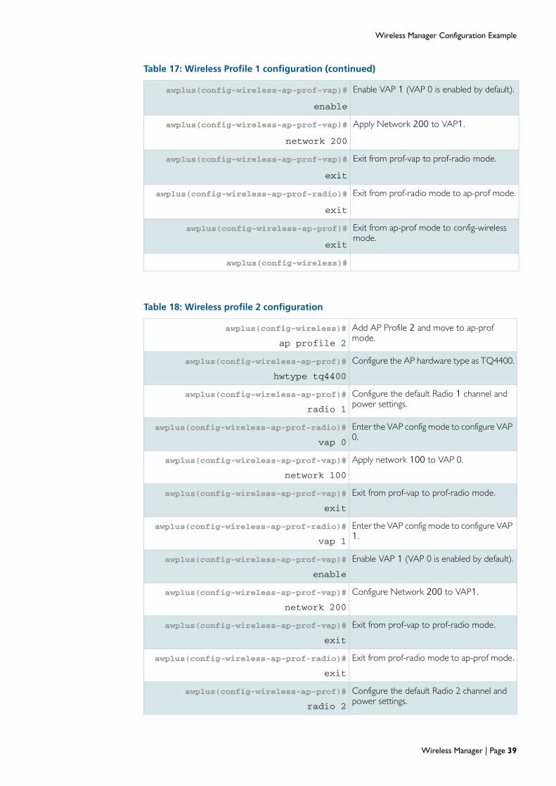
Configure the AP wireless profiles
The following steps are used to configure profile 1 for the TQ4600. Once configured, this profile can then be used to apply a common configuration to all APs of this type.
Table 17: Wireless Profile 1 configuration
awplus(config-wireless)#
ap profile 1
Add AP Profile 1 and move to ap-prof mode.
awplus(config-wireless-prof)#
hwtype tq4600
Configure the AP hardware type as TQ4600.
awplus(config-wireless-prof)#
radio 1
Enter configuration mode for Radio 1, using its default settings.
awplus(config-wireless-prof-radio)#
vap 0
Enter the VAP config mode to configure VAP 0.
awplus(config-wireless-prof-vap)#
network 100
Apply network 100 to VAP 0.
awplus(config-wireless-prof-vap#
exit
Exit from prof-vap to prof-radio mode.
awplus(config-wireless-prof-radio#
vap 1
Enter the VAP config mode to configure VAP 1.
awplus(config-wireless-prof-vap)#
enable
Enable VAP 1 (VAP 0 is enabled by default).
awplus(config-wireless-prof-vap)#
network 200
Configure network 200 to VAP 1.
awplus(config-wireless-prof-vap#
exit
Exit from prof-vap to prof-radio mode.
awplus(config-wireless-prof-radio)#
exit
Exit from prof-radio mode to ap-prof mode.
awplus(config-wireless-ap-prof)#
radio 2
Configure the default Radio 2 channel and power setting.s
awplus(config-wireless-ap-prof-radio)#
dot11n channel-bandwidth 40
Set the bandwidth for 802.11n at 40 MHz.
awplus(config-wireless-ap-prof-radio)#
vap 0
Enter the VAP config mode to configure VAP 0.
awplus(config-wireless-ap-prof-vap)#
network 100
Apply network 100 to VAP 0.
awplus(config-wireless-ap-prof-vap)#
exit
Exit from prof-vap to prof-radio mode.
awplus(config-wireless-ap-prof-radio)#
vap 1
Enter the VAP config mode to configure VAP 1.
Page 38 | Wireless Manager
Wireless Manager Configuration Example
awplus(config-wireless-ap-prof-vap)#
enable
Enable VAP 1 (VAP 0 is enabled by default).
awplus(config-wireless-ap-prof-vap)#
network 200
Apply Network 200 to VAP1.
awplus(config-wireless-ap-prof-vap)#
exit
Exit from prof-vap to prof-radio mode.
awplus(config-wireless-ap-prof-radio)#
exit
Exit from prof-radio mode to ap-prof mode.
awplus(config-wireless-ap-prof)#
exit
Exit from ap-prof mode to config-wireless mode.
awplus(config-wireless)#
Table 18: Wireless profile 2 configuration
awplus(config-wireless)#
ap profile 2
Add AP Profile 2 and move to ap-prof mode.
awplus(config-wireless-ap-prof)#
hwtype tq4400
Configure the AP hardware type as TQ4400.
awplus(config-wireless-ap-prof)#
radio 1
Configure the default Radio 1 channel and power settings.
awplus(config-wireless-ap-prof-radio)#
vap 0
Enter the VAP config mode to configure VAP 0.
awplus(config-wireless-ap-prof-vap)#
network 100
Apply network 100 to VAP 0.
awplus(config-wireless-ap-prof-vap)#
exit
Exit from prof-vap to prof-radio mode.
awplus(config-wireless-ap-prof-radio)#
vap 1
Enter the VAP config mode to configure VAP 1.
awplus(config-wireless-ap-prof-vap)#
enable
Enable VAP 1 (VAP 0 is enabled by default).
awplus(config-wireless-ap-prof-vap)#
network 200
Configure Network 200 to VAP1.
awplus(config-wireless-ap-prof-vap)#
exit
Exit from prof-vap to prof-radio mode.
awplus(config-wireless-ap-prof-radio)#
exit
Exit from prof-radio mode to ap-prof mode.
awplus(config-wireless-ap-prof)#
radio 2
Configure the default Radio 2 channel and power settings.
Table 17: Wireless Profile 1 configuration (continued)
Wireless Manager | Page 39

Wireless Manager Configuration Example
awplus(config-wireless-ap-prof-radio)#
dot11n channel-bandwidth 40
Set the bandwidth for 802.11n at 40 MHz.
awplus(config-wireless-ap-prof-radio)#
vap 0
Enter the VAP config mode to configure VAP. 0
awplus(config-wireless-ap-prof-vap)#
network 100
Configure network 100 to VAP 0.
awplus(config-wireless-ap-prof-vap#
exit
Exit from prof-vap to prof-radio mode.
awplus(config-wireless-ap-prof-radio)#
vap 1
Enter the VAP config mode to configure VAP 1.
awplus(config-wireless-ap-prof-vap)#
enable
Enable VAP 1 (VAP 0 is enabled by default).
awplus(config-wireless-ap-prof-vap)#
network 200
Configure Network 200 to VAP1.
awplus(config-wireless-ap-prof-vap)#
exit
Exit from prof-vap to prof-radio mode.
awplus(config-wireless-ap-prof-radio)#
exit
Exit from prof-radio mode to ap-prof mode.
awplus(config-wireless-ap-prof)#
exit
Exit from ap-prof mode to config-wireless mode.
awplus(config-wireless)#
Table 18: Wireless profile 2 configuration (continued)
Page 40 | Wireless Manager

Show Running Configuration Output
Show Running Configuration OutputThis section shows the complete show running config output of the tutorial network example. Note that there may be some small differences between this show output and the configurations shown in the tutorial sections. This is because changes have been made to make the tutorial examples easier to understand.---------------------------------------------------------------------------------------------------------------- !service password-encryption !no banner motd !username manager privilege 15 password 8 $1$bJoVec4D$JwOJGPr7YqoExA0GVasdE0 !no log console ! no service ssh !service telnet !service http !no clock timezone !snmp-server ! radius-server host 127.0.0.1 key naskeywmd !aaa authentication enable default localaaa authentication login default local aaa authentication wireless default group radius !crypto pki trustpoint local !crypto pki enroll local radius-server local server enable nas 127.0.0.1 key naskeywmd
user employee-name1 password emp-pass1
user employee-name2 password emp-pass2
user employee-name3 password emp-pass3
user employee-name4 password emp-pass4
user employee-name5 password emp-pass5 !ip domain-lookup !ip dhcp pool Employee-Pool
network 192.168.100.0 255.255.255.0
range 192.168.100.101 192.168.100.250
default-router 192.168.100.254 subnet-mask 255.255.255.0 ! ip dhcp pool Guest-Pool network 192.168.200.0 255.255.255.0 range 192.168.200.101 192.168.200.150 default-router 192.168.200.254 subnet-mask 255.255.255.0 ! ip dhcp pool AP-Mgmt-Pool network 192.168.30.0 255.255.255.0 range 192.168.30.1 192.168.30.10 default-router 192.168.30.254 subnet-mask 255.255.255.0 ! service dhcp-server
Wireless Manager | Page 41

Show Running Configuration Output
! no ip multicast-routing !spanning-tree mode rstp !service power-inline
no spanning-tree rstp enable !switch 2 card 1 provision ge24
switch 2 card 5 provision cfc960 ! vlan database vlan 30 name AP-Mgmt-Vlan vlan 100 name Employee-Vlan vlan 200 name Guest-Vlan vlan 30,100,200 state enable ! interface port1.1.1 description uplink switchport switchport mode trunk switchport trunk allowed vlan all switchport trunk native vlan none ! interface port1.1.2-1.1.5 description wireless switchport switchport mode trunk switchport trunk allowed vlan add 100,200 switchport trunk native vlan 30 ! interface port1.1.6-1.1.24 switchport switchport mode access ! interface port2.5.1-2.5.4 switchport switchport mode access ! interface vlan30 ip address 192.168.30.254/24 ! interface vlan100 ip address 192.168.100.254/24 ! interface vlan200 ip address 192.168.200.254/24 ! wireless country-code nz wireless enable no discovery vlan-list 1 discovery vlan-list 30 ip address 192.168.30.254/24
network 100 ssid Employee-SSID-1 vlan 100 security mode wpa-enterprise wpa versions wpa2 radius group-name auth radius
network 200 ssid Guest-SSID-1 vlan 200 security mode none ap profile 1 hwtype tq4600 radio 1 vap 0 network 100 vap 1 enable network 200 radio 2
Page 42 | Wireless Manager
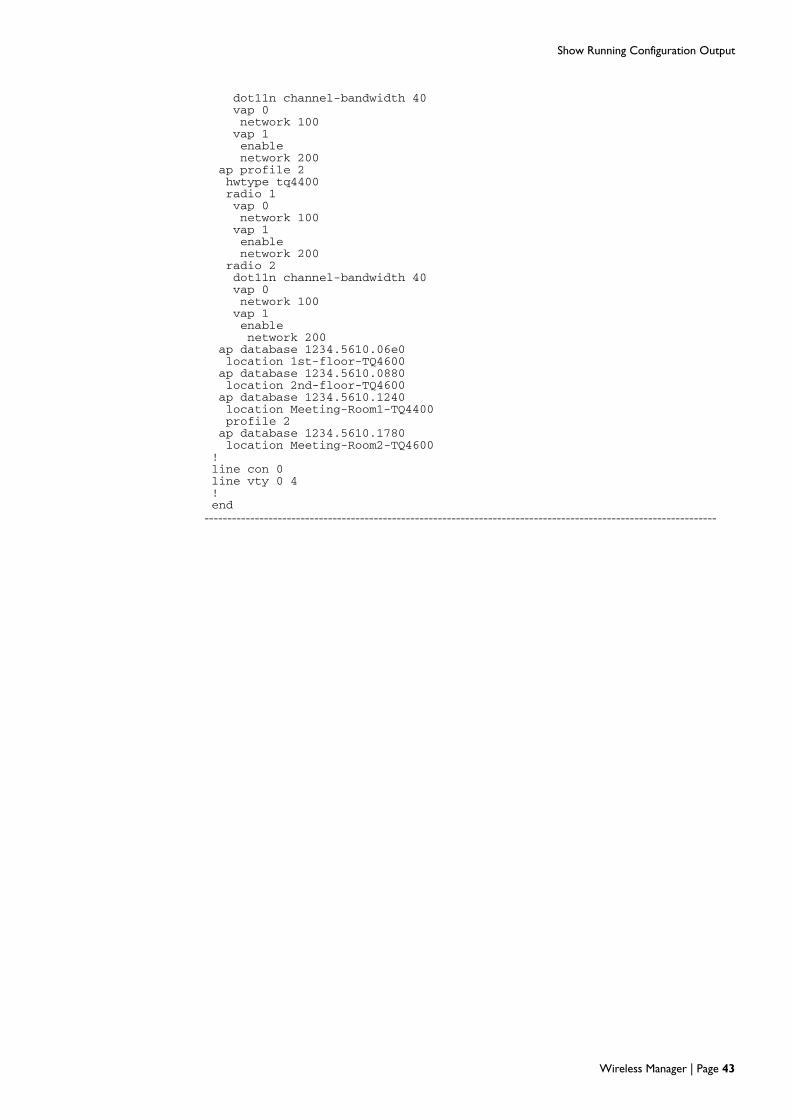
Show Running Configuration Output
dot11n channel-bandwidth 40 vap 0 network 100 vap 1 enable network 200 ap profile 2 hwtype tq4400 radio 1 vap 0 network 100 vap 1 enable network 200 radio 2 dot11n channel-bandwidth 40 vap 0 network 100 vap 1 enable network 200 ap database 1234.5610.06e0 location 1st-floor-TQ4600 ap database 1234.5610.0880 location 2nd-floor-TQ4600 ap database 1234.5610.1240 location Meeting-Room1-TQ4400 profile 2 ap database 1234.5610.1780 location Meeting-Room2-TQ4600 ! line con 0 line vty 0 4 ! end----------------------------------------------------------------------------------------------------------------
Wireless Manager | Page 43

Configuring different profiles on the same AP type
Configuring different profiles on the same AP type
In this example, the wireless traffic in a university library’s reading rooms is much higher than in other areas of the campus and requires resetting the frame fragmentation threshold to better manage the level of congestion. To manage this situation two profiles are created. Profile 1 is created for APs used to load the general settings to APs in the general campus area, and profile 2 is used to load the specific settings required to APs in the library area. Note that because the APs are all AT-TQ4600s, Profile 2 would need to specifically identify the MAC addresses of APs located in the library. Non library APs will be members of Profile 1 by default.
ConfigureProfiles 1& 2
Scope out the AP configuration requirements of each profile type and configure them as shown in Table 19 below.
Configure APMAC
addresses
Add the university APs to the database and assign them their appropriate profiles. This example shows two APs in the General-Campus area and two in the Library.The General-Campus APs have the MAC addresses 0000.5e00.5301 and 0000.5e00.5302.The Library APs have the MAC addresses 0000.5e00.5350 and 0000.5e00.5351.
Table 19 below shows how to register these MAC addresses to the AP database and assign them their appropriate profile.
Table 19: Wireless Profile 1 configuration for the university example
Configure Profile 2 for the General-Campus APs
awplus(config-wireless)#
ap profile 1
Add AP Profile 1 and move to config-wireless-prof mode.
awplus(config-wireless-ap-prof)#
hwtype tq4600
Configure the AP hardware type as TQ4600.
awplus(config-wireless-ap-prof)#
exit
Exit from ap-prof mode to config-wireless mode.
Configure Radios VAPs and networks etc to meet the General-Campus requirements.
Configure Profile 2 for the Library APs
awplus(config-wireless)#
ap profile 2
Add AP Profile 2 and move to config-wireless-prof mode.
awplus(config-wireless-ap-prof)#
hwtype tq4600
Configure the AP hardware type as TQ4600.
Configure Radios VAPs and networks etc to meet the Library requirements, remembering to reset the fragmentation-threshold to an appropriate value.
Table 20: AP database configuration
awplus#
configure terminal
Enter Configuration mode.
Page 44 | Wireless Manager

Configuring different profiles on the same AP type
awplus(config)#
wireless
Enter config-wireless mode
awplus(config-wireless)#
wireless enable
Enter config-wireless-ap mode
awplus(config-wireless-ap)#
ap database 0000.5e00.5301
Register the first General Campus AP to the database.
awplus(config-wireless-ap)#
location Engineering
Enter the details and location of the first AP.
awplus(config-wireless-ap)#
ap database 0000.5e00.5302
Register the second General Campus AP to the database.
awplus(config-wireless-ap)#
location Chemistry
Enter the details and location of the second AP.
Note that by default the above APs will be members of Profile 1
awplus(config-wireless-ap)#
ap database 0000.5e00.5350
Register the first Library AP to the database.
awplus(config-wireless-ap)#
location Library1
Enter the details and location of the first library AP.
awplus(config-wireless-ap)#
profile 2
Assign this AP to Profile2.
awplus(config-wireless-ap)#
ap database 0000.5e00.5351
Register the second Library AP to the database.
awplus(config-wireless-ap)#
location Library2
Enter the details and location of the second library AP.
awplus(config-wireless-ap)#
profile 2
Assign this AP to Profile2.
awplus(config-wireless-ap)#
exit
Exit to config-wireless mode
awplus(config-wireless)#
Table 20: AP database configuration (continued)
Wireless Manager | Page 45

Loading a new software image to a TQ Series AP
Loading a new software image to a TQ Series APFrom time to time you will need use Wireless Manager to load new software versions to the APs. This section shows a method of using TFTP to download a new software image.
Figure 9 below shows the wireless network with added TFTP server.
Figure 9: Wireless network with TFTP file server
After obtaining the image file, save it in an appropriate directory on the TFTP server. For this example the folder is called “ap_downloads” and the image file name is AT-TQ4600-3.0.0.img
Load the image file using TFTP
TFTP
server SBx8100SwitchBladex8100
CFC9601.5.x
AT-TQ4600
(2nd Floor)
AT-TQ4600
(1st Floor)
AT-TQ4600
(Mtg Rm1)
AT-TQ4400
(Mtg Rm2)
AP Profile 2
AP Profile 1
uplink Port
192.168.40.1
Port 1.1.3
Port 1.1.2
Port 1.1.5
Radio 1ad
Radio 2AP
Radio 1ad
Radio 2AP
Radio 1ad
Radio 2AP
Radio 1ad
Radio 2AP
Port1.1.x
Physical_Network_Example.eps
Table 21: Load the image file to all APs of the same type
awplus#
wireless ap download tq4600 tftp://192.168.40.1/ap_downloads/at-tq4600-
3.0.0.img
Set a TFTP path and file name for the specific AP type, an AT-TQ4600 in this example.
awplus#
wireless ap download tq4600 start
Initiate the file download to all TQ4600 APs
awplus#
show wireless ap download
Check that the file has loaded
Page 46 | Wireless Manager

Loading a new software image to a TQ Series AP
Note that once an AP has completed downloading its new image file, it will automatically reboot, and come up again running the new image.
Table 22: Load the image file to a specific AP
awplus#
wireless ap download tq4400 tftp://192.168.40.1/ap_downloads/at-tq4400-
3.0.0.img
Set a TFTP path and file name for the specific AP type, AT-TQ4400 in this example.
awplus#
wireless ap download 0000.5e00.5320 start
Initiate the file download to the AP with MAC address 0000.5e00.5320
awplus#
show wireless ap download
Check that the file has loaded
Output 1: Example output from the show wireless ap download command
awplus#show wireless ap download image 1 File Name.......................... AT-TQ4400-3.0.0.imgimage 1 File Path.......................... server image 2 File Name.......................... image 2 File Path.......................... image 3 File Name.......................... image 3 File Path.......................... image 4 File Name.......................... image 4 File Path.......................... image 5 File Name.......................... image 5 File Path.......................... image 6 File Name.......................... image 6 File Path.......................... image 7 File Name.......................... image 7 File Path.......................... image 8 File Name.......................... image 8 File Path.......................... Server Address............................. 192.168.40.1 Group Size................................. 10 Download Type.............................. Image 1 Download Status............................ Code Transfer In Progress Total Count................................ 1 Success Count.............................. 0 Failure Count.............................. 0 Abort Count................................ 0awplus#
Wireless Manager | Page 47

Network Example - Constraints and Enhancements
Network Example - Constraints and EnhancementsThe network designs and configurations shown in this guide have been created for simplicity and ease of understanding, rather than as stencils to be copied for a practical network. The following two aspects in particular need to be considered.
Security settings
The example network shows Guest users having totally open access. As a general rule we recommend applying access security even to guest access. See "Access security" on page 20. However, there may be users who want to provide public network access and are able to manage its security aspects, but these situations are outside the scope of this guide.
Access at desired network mode/speed
The example network has the simplicity of containing only two user types, Employee and Guest, for whom it attempts to provide a simple method of dual (current and legacy)connectivity. The intention is that users with later devices can connect at 5 GHz—possibly utilizing MIMO and spatial streaming—while users with older (legacy) devices have the option of connecting at 2.4 GHz. However, the method employed in the example network may not be sufficient to ensure that users with faster devices are always allocated the faster network. The following enhancement, although making the network slightly more complicated to configure, does provide a more positive method for each user to specifically choose their network connectivity mode/speed.
The modified network uses the following four VAPs:
Employee (a/n)
Guest (a/n)
Employee (b/g)
Guest (b/g)
This enhanced configuration is illustrated in Figure 10 on page 49. Employee and Guest users are both offered the choice of two networks: an a/n network that only provides access at 5 GHz, and a b/g network that only provides access at 2.4 GHz.
Page 48 | Wireless Manager

Network Example - Constraints and Enhancements
Figure 10: Enhanced Configuration
TQ4600
Profile 1
VAP 1 VAP 2Radiomode
802.11b/g/n(the default)
Network 11
SSIDEmployee (b/g)
Network 12
SSIDGuest (b/g)
Radio 1
VAP 3 VAP 4Radiomode
802.11a/n
Network 13
SSIDEmployee (a/n)
Network 14
SSIDGuest (a/n)
Radio 2
AP_config_4600_Enhanced.eps
AP Configuration Process
(Enhanced) for Profile 1
VLAN 6VLAN 5VLAN 6VLAN 5
Wireless Manager | Page 49

Network Example - Constraints and Enhancements
Configuration overview of enhanced network
Table 23: AP locations and configuration for enhanced configuration
AP Type Location Radio VAP Network SSIDVLAN
ID MAC Address AP Profile
AT-TQ 4600 1st Floor Radio 1 VAP 1 Employee (b/g) 5 0000.5e00.5300 Profile 1
VAP 2 Guest (b/g) 6 0000.5e00.5301 Profile 1
Radio 2 VAP 3 Employee (a/n) 5 0000.5e00.5310 Profile 1
VAP 4 Guest (a/n) 6 0000.5e00.5311 Profile 1
AT-TQ 4600 2 nd Floor Radio 1 VAP 0 Employee (b/g) 5 0000.5e00.5320 Profile 1
VAP 1 Guest (b/g) 6 0000.5e00.5321 Profile 1
Radio 2 VAP 0 Employee (a/n) 5 0000.5e00.5330 Profile 1
VAP 1 Guest (a/n) 6 0000.5e00.5331 Profile 1
AT-TQ 4600 Meeting Room 1 Radio 1 VAP 0 Employee (b/g) 5 0000.5e00.5340 Profile 1
VAP 1 Guest (b/g) 6 0000.5e00.5341 Profile 1
Radio 2 VAP 0 Employee (a/n) 5 0000.5e00.5350 Profile 1
VAP 1 Guest (a/n) 6 0000.5e00.5351 Profile 1
AT-TQ 4400 Meeting Room 2 Radio 1 VAP 0 Employee (b/g) 5 0000.5e00.5360 Profile 2
VAP 1 Guest (b/g) 6 0000.5e00.5361 Profile 2
Radio 2 VAP 0 Employee (a/n) 5 0000.5e00.5370 Profile 2
VAP 1 Guest (a/n) 6 0000.5e00.5371 Profile 2
Table 24: Create the VLANs
Feature applied or configured Step
VLAN 30 Create VLAN 30 and name it AP-Mgmt-Vlan
VLAN 5 Create VLAN 5 and name it Employee
VLAN 6 Create VLAN 6 and name it Guest
Table 25: Configure the VLANs
Feature applied or configured Step
VLAN 30 Set the primary address to be 192.168.30.254
VLAN 5 Set the primary address to be 192.168.111.254
VLAN 6 Set the primary address to be 192.168.112.254
Page 50 | Wireless Manager

Network Example - Constraints and Enhancements
Table 26: Overview of the AP wired network, enhanced configuration
Feature applied or configured Step
Enable the Wireless Manager.
VLA
N
1
Remove VLAN 1 as a VLAN capable of sending L2 multicast discovery frames.
VLA
N
30
Add VLAN 30 to the VLANs capable of sending L2 multicast discovery frames.
Configure the IP address of Wireless Manager as 192.168.30.254.
Net
wor
k 11
Enter the network config mode for Network 11.
SSID
Em
ploy
ee (
b/g)
Configure the Employee (b/g) SSID.
VLA
N 5
Configure VLAN 5 as the default VLAN on Network 11
WPA
Sec
urity
Configure encryption to wpa-enterprise.
Set the security mode to be WPA2.
Enab
leR
AD
IUS Set the group of RADIUS servers to which to send authentication
requests to be the group 'radius'
Net
wor
k 12
Enter the network config mode for Network 12.
SSID
Gue
st (
b/g)
Configure the Guest (b/g) SSID.
VLA
N 6
Configure VLAN 6 as the default VLAN on Network 12
WPA
Sec
urity
Configure encryption to wpa-enterprise.
Set the security mode to be WPA2.
Enab
leR
AD
IUS
(Opt
iona
l) Set the group of RADIUS servers to which to send authentication requests to be the group 'radius'
Net
wor
k 13
Enter the network config mode for Network 13.
SSID
Em
ploy
ee (
a/n)
Configure the Employee (a/n) SSID.
VLA
N 5
Configure VLAN 5 as the default VLAN on Network 13
WPA
Sec
urity
Configure encryption to wpa-enterprise.
Set the security mode to be WPA2.
Enab
leR
AD
IUS Set the group of RADIUS servers to which to send authentication requests to be the group 'radius
Net
wor
k 14
Enter the network config mode for Network 14.
SSID
Gue
st (
a/n)
Configure the Guest (a/n) SSID.
VLA
N 1
14
Configure VLAN 6 as the default VLAN on Network 14
WPA
Sec
urity
Configure encryption to wpa-enterprise.
Set the security mode to be WPA2.
Enab
leR
AD
IUS
(Opt
iona
l) Set the group of RADIUS servers to which to send authentication requests to be the group 'radius
Wireless Manager | Page 51

Network Example - Constraints and Enhancements
This configuration process can be repeated for additional profiles or specific APs.
Table 27: Configuration Overview for wireless networks
Feature applied or configured Step
Profile 1 Add AP Profile 1 and move to ap-prof mode.
TQ Type Specify the AP as a TQ Type (e.g. TQ4600).
Note that at this point you can configure any of the available Radio configuration options.By default Radio 1 operates in the IEEE 802.11b/g/n mode.For more information see "Configurable radio options" on page 23
Radio 1 Configure the Radio 1 channel and power settingsor accept its defaults.Note that Radio 1 runs in b/g mode by default.
A
P pr
ofile
1 T
Q T
ype
set
to T
Q 4
600
R
adio
1
VAP 1 Enter the VAP config mode to configure VAP 2
Enable VAP 1.
Network11
Apply Network 11 to VAP1.
VAP 2 Enter the VAP config mode to configure VAP 2
Enable VAP 2.
Network 12
Apply Network 12 to VAP2.
Radio 2 Configure the Radio 2 channel and power settingsor accept its defaults.Using the command “mode, Wireless Manager AP Pro-file Radio,” set the mode to a-n.
Rad
io 2
Note that at this point you can configure any of the available Radio configuration options.For more information see "Configurable radio options" on page 23
VAP 3 Enter the VAP config mode to configure VAP 3
Enable VAP 3.
Network13
Apply Network 13 to VAP3.
VAP 4 Enter the VAP config mode to configure VAP 4
Enable VAP 4.
Network14
Apply Network 14 to VAP4.
Page 52 | Wireless Manager

Aspects and Issues of WiFi Transmission
Aspects and Issues of WiFi TransmissionThis section introduces some specific aspects and issues related to WiFi transmission
Modulation coding scheme
The Modulation Coding Scheme (MCS) is a method defined within the IEEE802.11 standard that quantifies transmission speed and modulation complexity. The modulation, coding, and spatial channels employed are assigned to a graded rating called the MCS Index. The index value is determined first by the number of spatial streams employed, then by modulation complexity. Table 28 below shows a simplified MCS Index Chart based on that shown in the IEEE802.11n standard. This chart shows how index numbers increase with modulation complexity with each spatial stream (approximately equal to number of antennas used). The range of data rates per index step is dependent on the inter-frame spacing used for each frame type, i.e. for those frame types that have a short inter-frame gap, it is possible to achieve a higher data rate.
The modulation index table is used as part of the inter-working capability dialogue that takes place when a wireless client attempts to attach to an AP.
On the TQ series of Access Points, the MCS Index can be edited by Wireless Manager’s mcs index command. This command modifies an AP’s basic defaults and enables you to turn selected index values on or off. However, unless your network is suffering from specific MCS related problems, it is unlikely that you will need to change these settings from their defaults, because wireless clients individually auto-negotiate their MCS levels when they attach to an AP.
The basic MCS Index can be edited by Wireless Manager’s mcs index command. This command modifies the AP’s basic defaults (also their range of capabilities). These capabilities and default settings are product-model dependent and are presently:
AT-TQ4600 —Supports MCS Indices 0 to 23
AT-TQ4400— Supports MCS Indices 0 to 15
One possible situation that could justify reducing the MCS index might be issues with multicast transmission, where all attached clients need to simultaneously and reliably receive the same transmission.
Wireless Manager | Page 53

Aspects and Issues of WiFi Transmission
1) The number of spatial streams is approximately equal to the lowest number of antennas used at either the transmitter or receiver.
Table 28: Simplified MCS Index Chart
MCSIndex
Spatial streams
antennas1
Modulationtype
CodingRatio
Max data rate(Mbps)
@ 20 MHz
Max data rate(Mbps)
@ 40 MHz
0 1 BPSK 1/2 6.5 to 7.2 13.5 to 15
1 1 BPSK 1/2 13 to 14.4 27 to 30
2 1 QPSK 3/4 19.5 to 21.7 40.5 to 45
3 1 16-QAM 1/2 26 to 28.9 54 to 60
4 1 16-QAM 3/4 39 to 43.3 81 to 90
5 1 16-QAM 2/3 52 to 57.8 108 to 120
6 1 16-QAM 3/4 58.5 to 65 121.5 to 135
7 1 16-QAM 5/6 65 to 72.2 135 to 150
8 2 BPSK 1/2 13 to 14.4 27 to 30
9 2 BPSK 1/2 26 to 28.9 54 to 60
10 2 QPSK 3/4 39 to 43.3 81 to 90
11 2 16-QAM 1/2 52 to 57.8 108 to 120
12 2 16-QAM 3/4 78 to 86.7 162 to 180
13 2 16-QAM 2/3 104 to 115.6 216 to 240
14 2 16-QAM 3/4 117 to 130 243 to 270
15 2 16-QAM 5/6 130 to 144.4 270 to 300
16 3 BPSK 1/2 19.5 to 21.7 40.5 to 45
17 3 BPSK 1/2 39 to 43.3 81 to 90
18 3 QPSK 3/4 58.5 to 65 121.5 to 135
19 3 16-QAM 1/2 78 to 86.7 162 to 180
20 3 16-QAM 3/4 117 to 130 243 to 270
21 3 16-QAM 2/3 156 to 173.3 324 to 360
22 3 16-QAM 3/4 175.5 to 195 364 to 405
23 3 16-QAM 5/6 195 to 216.7 405 to 450
Page 54 | Wireless Manager

Aspects and Issues of WiFi Transmission
Managing traffic, and collision avoidance
Simultaneous transmissions can occur in both terrestrial and wireless networks. However, the way they are managed is quite different. Terrestrial networks can manage collisions by “detecting” overlapping transmissions and implementing a back-off and retransmit process known as CSMACD, where the CD represents Collision Detection. Wireless networks however, are unable to implement this process because a radio cannot transmit and receive on the same frequency at the same time. So instead of detecting collisions, wireless networks try to avoid them. Each AP, or client device, listens for quiet periods within their operating channel frequency before transmitting a frame. This process is known as CSMACA, where the CA represents Collision Avoidance.
If two stations happen to both sense the same quiet carrier period and simultaneously begin transmitting, their frames will overlap. This will corrupt both frames and cause their Frame Check Sequence (FCS) to show an error. The stations will then retransmit after waiting a semi-random period.
This system can provide good performance where the network loading is light and the wireless band is free of interference. However, where network utilization is high, collisions can slowdown transmission throughput.
RTS/CTS dialogue
One option available where collisions are causing network problems is to initiate a function known as Request to Send/Clear to Send (RTS/CTS). On the TQ series of APs, the RTS/CTS function is turned on by the rts-threshold command. When this command is set, the AP will initiate the RTS/CTS dialogue for any frame above a preset threshold length. If a station wishes to send a frame that exceeds the threshold length, it will first send a short RTS frame to the AP. If the wireless carrier is clear, the AP will reply with a CTS frame. On hearing this frame, all other stations will wait a preset time before beginning their transmissions.
Note that initiating RTS/CTS will itself introduce an overhead caused by the additional frames transmitted and their spacing intervals. However, the overall gain may still be worthwhile depending on the severity of the problem.
RTS/CTS and the hidden node problem
RTS/CTS is sometimes applied where there are problems due to the existence of a hidden node. A hidden node is client device that is within transmission range of its AP but out of range of other client devices—possibly located on the far side of the AP. Thus the hidden node may start transmitting—sensing a clear channel—unaware that other (distant) devices are already transmitting. Because the AP will sense both transmissions it will consider these to be collisions. By applying RTS/CTS, the hidden node will first send an RTS frame then wait until a CTS from the AP tells it the channel is clear.
Note that for RTS/CTS to be effective in this situation, it needs to be set on the hidden node itself, rather than on its AP.
Wireless Manager | Page 55

Aspects and Issues of WiFi Transmission
Collisions caused by wireless interference
Interference caused by cordless phones, microwaves and other equipment can appear to a wireless network as overlapping transmissions and treated as collisions. these signals are spurious, they cannot be addressed by setting RTS/CTS. If you are unable to locate the source of the problem, fragmenting the frame size might help. This is because an individual interference hit will only corrupt a single frame fragment rather than the whole frame.
Detecting collisions by using show output commands
If you suspect that your network is suffering from high collisions rates, we suggest running the following show commands and inspecting their output for frame errors and retransmissions:
show wireless ap radio statistics
show wireless ap client statistic.
Page 56 | Wireless Manager

Wireless Terminology Glossary
Wireless Terminology GlossaryMost of the terminology used to describe WiFi-LAN connectivity is defined within the IEEE standard 802.11. The standards document itself contains several thousand pages of wireless networking specifications that are primarily intended as an engineers’ and designers’ reference. This glossary however, introduces some of the more commonly used terms that are specific to the AT-Wireless Manager product and its operating standards and features.
802.11 A family of wireless standards defined by the IEEE (Institution of Electrical and Electronics Engineers). 802.11 is the base standard to which a suffixes (b, n etc) are added as modifications to the standard are ratified. See "IEEE 801.11 operating modes" on page 9.
AAA An acronym that defines three aspects of network security, Authentication, Authorization and Accounting. See "Configure the RADIUS and AAA functions" on page 30.
Aggregation The process of combining individual MPDUs into a single frame.
AP Access Point: A device that provides a point of connectivity for wireless clients. These clients connect to an AP using a process known as association. APs usually have two components: a wireless component that communicates with its wireless clients, and a wired component that provides communication to the terrestrial network known as the Distribution System (DS). APs can also incorporate additional functions such as bridging and routing, DHCP, and RADIUS. See "Access Points (APs)" on page 5.
The APs described in this guide are the Allied Telesis TQ Series.
AP Profile An AP profile is a set of wireless configuration settings that can be named and applied to a specific set of APs. The selected AP set can be either all TQs of a particular type or by TQ type and MAC address. See "AP Profiles" on page 7.
Authentication A process of verifying that users or their devices are genuine. Elements involved in the authentication processes covered are Radius and AAA. See "Configure the RADIUS and AAA functions" on page 30.
Bandwidth In terrestrial networks, bandwidth is the speed of the data over the wire, usually measured in bits per second, kilobits per second (kbps) or megabits per second (Mbps).
In radio networks the bandwidth is the frequency band occupied by the radio transmission, usually measured in MHz or GHz.
BeaconFrame
A hello message transmitted by an AP. Beacon frames advertise an AP’s presence to its clients and provide connectivity information such as the network names they support together with configuration information. Client devices can use the information in a beacon frame as the basis for network association.
BeaconInterval
The time period between the regular transmission of beacon frames.
Wireless Manager | Page 57

Wireless Terminology Glossary
BPSK Binary Phase Shift Keying: One of the early encoding schemes used in WiFi transmissions. It involves shifting the phase between two carriers transmitting at the same frequency. BPSK is still supported and is the lowest level of the modulation types specified in the MCS index. See "Modulation coding scheme" on page 53.
Bridge A device used to provide a layer-2 connection between two network segments.
BSS Basic Service Set: An entity that comprises a virtual AP and its associated wireless connected devices.
CSMACA Carrier Sense Multiple Access Collision Avoidance: A method by which wireless devices sense a space in transmissions in their operating frequency band before transmitting a wireless message. Employing this method reduces the likelihood of overlapping transmissions (collisions) occurring. See "Managing traffic, and collision avoidance" on page 55.
Channel In a WiFi network, a channel is the band of operating frequencies used to carry a wireless transmission. See "Radio frequency management" on page 9.
DFS Dynamic Frequency Shift: A method of dynamically shifting an APs operating channel, usually when it senses an overlapping Radar signal. The frequency bands requiring DFC is managed by National Regulating Bodies. See "Wireless channels in the 5.0 GHz band" on page 11.
DHCP Dynamic Host Control Protocol provides a method of automatically allocating pre-defined IP addresses to end point devices. See "Configure DHCP" on page 31.
DS Distribution System: The terrestrial portion of a WiFi network that provides the wired infrastructure that interconnects APs or connects an AP to network servers etc.
DNS Domain Name Service. This translates service addresses presented in URL format into IP addresses.
EBSS Extended Basic Service Set. A BSS that spans more than one VAP. See "BSS" on page 58.
Encryption A method of encoding (scrambling) messages so that only those who have been entrusted with decryption keys can read them. Encryption methods employed in wireless networks are WEP (Wired Equivalent Privacy) (not recommended), WPA (WiFi Protected Access), WPA2 Personal and WPA2 Enterprise. See "Access security" on page 20.
ESSID Extended Service Set Identifier. An SSID that spans more than one VAP. See "SSID" on page 59.
InfrastructureMode
A wireless operating mode in which wireless stations connect via an AP rather than connecting directly (known as ad hoc mode).
ISM A band of radio frequencies that are assigned for Industrial Scientific and Medical purposes. The ISM frequency bands may be used/shared by licensed or unlicensed users, subject to local/national regulations.
Page 58 | Wireless Manager

Wireless Terminology Glossary
MCS Index Modulation Coding Scheme Index; A method of coding used to indicate the level of complexity employed by a wireless transmission. Factors applied are modulation, coding and number of spatial channels. Depending on the complexity employed, the transmission is assigned a graded value known as the MCS Index. See "Modulation coding scheme" on page 53.
MIMO Multiple In Multiple Out is the ability to transmit multiple signal streams via different antennas at the same transmission frequency. To achieve this, the transmitter and receiver use complex encoding and decoding techniques such as "Spatial Streaming" on page 59.
Probe A management frame sent by a wireless client to an AP requesting its association to AP. In addition to the request itself, probes contain information on the configuration and operating capability of the client.
QPSK Quadrature Phase Shift Keying: An encoding scheme used in WiFi transmissions. It encodes two binary bits (four combinations) at a time by associating each binary combination with the phase of the carrier when compared to a reference frequency. Where the phase of the combined carrier and its reference signal can lie in one of four quadrants.
RADIUS A protocol for communicating with a centralized server that provides AAA services. See "Wireless Manager Configuration Example" on page 14.
SpatialStreaming
A method of transmitting multiple wireless signals over a single carrier frequency using multiple antennas, where each signal takes a different path (spatial stream). By analyzing direct signals plus those due to reflections at the receiver, the original signals can be separated and extracted. For example, the three antennas used by the AT-TQ4600 APs provide a theoretical throughput of 3 antennas x 75 Mbps x 2 = 450 Mbps. Note that both sender and receiver need the same capability and number of antennas. In practice, throughput is limited by the common capability of the AP and client together with physical and wireless environmental constraints.
SSID A Network Name comprised of up to 32 characters. Internally these names are defined by a 32 binary character Service Set ID (SSID). In practice the network name is often a user-recognizable term such as “Customer-Network”. Note that strictly speaking an SSID relates to a single AP environment. See "Wireless network entities and components" on page 5.
VLAN Virtual Local Area Network. A separate portion of a physical network that contains its own collision domain and appears to the user as a separate physical network.
WEP Wired Equivalent Privacy is an early wireless encryption method used to increase security on wireless networks. This method is no longer considered to offer sufficient protection to users, and its use is discouraged. The IEEE 802.11n standard specifically disallows WEP based encryption. See "Access security" on page 20.
WPA WiFi Protected Access: An enhanced method of data encryption used in wireless networks. There are various levels of WPA: WPA-Personal and WPA-Enterprise. See "Access security" on page 20.
Wireless Manager | Page 59

Wireless Terminology Glossary
WPA2 WiFi Protected Access 2: An enhanced version of WPA that utilizes the Advanced Encryption Standard (AES) and replaces Temporal Key Integrity Protocol (TKIP) with the more secure CCMP (Counter Cipher Mode with Block Chaining Message Authentication Code Protocol). See "Access security" on page 20.
Page 60 | Wireless Manager

C613-22065-00 REV A
North America Headquarters | 19800 North Creek Parkway | Suite 100 | Bothell | WA 98011 | USA | T: +1 800 424 4284 | F: +1 425 481 3895Asia-Pacifi c Headquarters | 11 Tai Seng Link | Singapore | 534182 | T: +65 6383 3832 | F: +65 6383 3830EMEA & CSA Operations | Incheonweg 7 | 1437 EK Rozenburg | The Netherlands | T: +31 20 7950020 | F: +31 20 7950021
alliedtelesis.com© 2015 Allied Telesis Inc. All rights reserved. Information in this document is subject to change without notice. All company names, logos, and product designs that are trademarks or registered trademarks are the property of their respective owners.