Embed Size (px)
Citation preview
Wireless LISP: Prototyping and EvaluationA LISP Implementation in the BOWL Testbed at Deutsche
Telekom Labs
Marc Ferrer Almirall
Technische Universität Berlin
Fakultät IV Elektrotechnik und Informatik Intelligent Networks / Intelligente Netze (INET)
Research Group of Prof. Anja Feldmann, Ph.D
April 2011Aufgabenstellerin: Prof. Anja Feldmann,
Betreuer: Luigi Iannone

ACKNOWLEDGEMENTS
I thank my supervisor, Luigi Iannone, for the opportunity he has given to me for developing a master thesis in the Deutsche Telekom Laboratories, and for his support all along the making of this
thesis.
I would like to express my sincere gratitude to Ruben Merz, who helped me in the technical part of the thesis, providing me knowledge and solutions, as well as having the technical supervisor role.
I thank also Thomas Huehn for his help in my search of a master thesis subject and the opportunity he gave to me contacting my supervisor.
I would like also to thank all the BOWL's team, specially Ruben Merz, Thorsten Fischer, Cigdem Sengul, Robin Kuck, Thomas Huehn, Mustafa Al-Bado, Julius Schulz-Zander and Benjamin Vahl for their support in the daily work and for the patience they had with my persistent questions and
queries.
- 2 -

INDEX
1 Introduction...........................................................................................................................................4
2 LISP Specification.................................................................................................................................6
2.1 General Overview...........................................................................................................................6
2.2 LISP Network Elements.................................................................................................................8
2.3 LISP Encapsulation Details............................................................................................................9
2.4 EID-to-RLOC Mapping System...................................................................................................11
3 Deployment Environment....................................................................................................................18
3.1 Software Tools..............................................................................................................................18
3.2 The BOWL Testbed......................................................................................................................21
3.3 The BOWL Operational Modes....................................................................................................23
3.4 The BOWL Management Architecture.........................................................................................25
3.5 The Basic BOWL Configuration..................................................................................................26
4 LISP Implementation...........................................................................................................................31
4.1 LISP Implemented Features..........................................................................................................31
4.2 LISP-Click Architecture...............................................................................................................33
4.3 LISP Map-Server Implementation................................................................................................40
4.4 Setting up the BOWL Platform for LISP......................................................................................43
4.5 LISP Examples..............................................................................................................................45
5 Evaluation............................................................................................................................................52
5.1 Local Traffic.................................................................................................................................53
5.2 Internet Traffic..............................................................................................................................73
6 Comparison LISP-IPIP.........................................................................................................................74
6.1 Static Scenario..............................................................................................................................74
6.2 Mobility Scenario..........................................................................................................................75
7 Conclusions..........................................................................................................................................79
8 References............................................................................................................................................82
- 3 -

1. INTRODUCTION
This thesis is focused on a subject that currently is in big developement: the wireless networks. Since the first Wireless Access Network appeared in the 1970, a lot of researchers have improved this technology up until today, where every home, university or office has a WLAN to connect to other networks such as the Internet. Despite the big evolution of the wireless networks, they are still a development subject for researchers, who want to improve their characteristics or to use them for developing network protocols, which only have been tested over wire so far. This is the case of the research done in this project: the implementation of the LISP protocol on wireless multi-hop networks.
The LISP (Locator-Identifier Separation Protocol) protocol is a network protocol that recently has been proposed as a solution for the huge growth of the Internet. Its proposal is to separate, in terms of IP addresses, the end-host devices (identifiers) from the routers that facilite their reachability or locate them in large networks such as Internet (locators). The IETF1 has already referenced this protocol by specifying its basic principles, while it has let other domains become open subjects for further investigation. One of these subjects is the LISP Mapping System, a database system needed in the LISP implementation in order to relate identifiers with locators. In this project, a proposal for a LISP Mapping system has been implemented.
One of the subjects which still need more research in the Wireless Access Networks domain is the so-called roaming or mobility. In a WLAN formed by fixed stations (or access points) and mobile stations (or clients), the roaming process is defined by the movement of a mobile station from one access point to another due to the weakness of the signal strength received. One of the goals of this thesis is to research in the wireless mobility subject by using the LISP protocol, which can be a solution to improve mobility performance.
This project is implemented within BOWL (Berlin Open Wireless Lab), a project of the Intelligent Networks (INET) researchers group at Deutsche Telekom Laboratories. It provides an open research platform for the wireless networking community, in which several wireless networks are available for researchers to carry out investigation in the wireless networking domain.
The first goal of this work is to develop a real LISP site in the Wireless Mesh Network from the Deutsche Telekom Laboratories. In order to do it, it has been taken as a starting point the previous implementation of the LISP protocol over wired networks, developed by Damien Saucez, a PhD student from the University Catholique of Louvain (Belgium). Hence, the innovation part of this proposal is to use this implementation carried out over wire to achieve a LISP environment in a wireless scenario.
The second goal of this proposal is, once in the wireless networking domain, to carry out investigation about the mobility subject. Despite the fact that LISP is expected to face the scalability problem in wired networks, in the wireless domain it is expected to have positive results regarding mobility. This is an area of ongoing research that depends mostly on the Mapping System implementation part, considering that when a wireless client roams, he changes the locator that has associated. In this thesis is proposed to research in this domain and achieve material results.
Another main objective of this thesis is to research in the LISP protocol itself, proposing an implementation of a LISP Mapping System that respects the LISP principles specified by the IETF group.
Finally, the solution proposed will be compared to the default configuration set up in the infrastructure where the Deutsche Telekom BOWL sits: a Wireless Mesh muti-hop configuration developed using the Click
1Internet Engineering Task Force, a group of academic and industry experts which main activity is to make the Internet work better by producing high quality, relevant technical documents that influence the way people design, use, and manage the Internet.
- 4 -

Modular Router2 which uses the IP-in-IP tunneling protocol as a way to route packets from one access point to another over the mesh netowork. At first sight, both IP-in-IP and LISP protocols have significant components in common, since both use the tunneling process to route and forward the traffic over the Wireless Mesh Network, carrying out the encapsulation process of the packets on every access point. Thus, it is expected to be an interesting subject the fact of reporting the difference between both protocols, with the main goal to explore the limitations and advantatged of the LISP protocol in respect to the IP-in-IP one.
In order to achieve the goals proposed above, along this thesis it will be reported, first of all, the theoretical principles of the LISP protocol, followed by the description of the current IP-in-IP implementation in the BOWL testbed. Second, the proposal of the specific LISP implementation of this project will be fully described. Next, the proposal will be tested providing real measurements with the main objective of achieving material results on the principles defended, testing at the same time the IP-in-IP protocol in order to have a comparison with the results obtained for the LISP implementation. Both protocols will be compared, ending up with the conclusions that will close this thesis.
2 See Section 3.1.1 for further information.
- 5 -

2. LISP SPECIFICATION
2.1. LISP Overview
The Locator/Identifier Separation Protocol (LISP) is based on the idea of splitting the current routing and addressing architecture into non-routable Endpoint Identifiers (called EIDs), which define the endpoint network devices, and routable Routing Locators (RLOCs), which describe how a device is attached to the network.
The creation of this protocol was initially motivated by the problems that were appearing with the dramatic growth of the Internet routing system, namely BGP3, which follows a hierarchical architecture. For a network of arbitrary connected N nodes, it is possible to devise a hierarchical clustering scheme where nodes inside a single cluster only have to know routes to the nodes of the same cluster and routes to other clusters, assigning addresses to them following the hierarchical structure. In this architecture, the size of the routing table on each router is of order O(log(N)). With the Internet growth, which was basically a result of the increasing number of multi-homed sites, this routing architecture began to be unstable, due mainly to three problems. Firstly, this approach required strict and topology based addressing, which was perfect in a static environment but does not work with mobile end-hosts changing its point of attachment. Secondly, it was not a optimized routing system because every cluster had a limited knowledge of the outside topology. Thirdly, the addressing space was hierarchical following the network cluster topology. This three issues led into scalability problems and thus the necessity of new routing protocols in order to solve it.
In addition to these problems, the idea of using a single IP address for both identifying a device and where this device is located in the whole network topology began to fail, because it required topological address assignment and a limited margin for topology changes. Here is when LISP appeared, solving this necessity of separating the device identifiers and its location in the network.
The main contributor to the LISP protocol is the Internet Engineering Task Force (IETF). Concerning LISP, the IETF group has written its main specification, as well as the specifications of all the branches in relationship to LISP. The LISP protocol described in this thesis is based on such specifications, specially the [LISP], the [LISP-MS] and the [INTERWORK].
2.1.1. LISP principles
As already said above, LISP crates two orthogonal address spaces: one serving to identify locations (RLOCs or Routing Locators), which are topologically assigned to network attachment points and used for routing and forwarding packets through the network, and another serving to identify endpoint devices (EIDs or Endpoint Identifiers), which are assigned independently from the network topology, and typically have globally non-routable IP addresses assigned. Both RLOCs and EIDs are syntactically identical to IP address, it is the semantics of how they are used that differs. This is one of the advantages of implementing LISP in already developed Internet sites, because LISP is transparent to the core network.
3 The Border Gateway Protocol (BGP) is the protocol backing the core routing decisions on the Internet. It maintains a table of IP networks or prefixes which designate network reachability among autonomous systems. It makes routing decisions based on path, network polices and rule sets.
- 6 -
In order to separate this two address spaces, tunneling4 is implemented encapsulating the packets with an outer header containing the RLOCs and keeping the inner header for EIDs. In addition, this tunneling implies a mapping system to provide functions that relate both spaces.
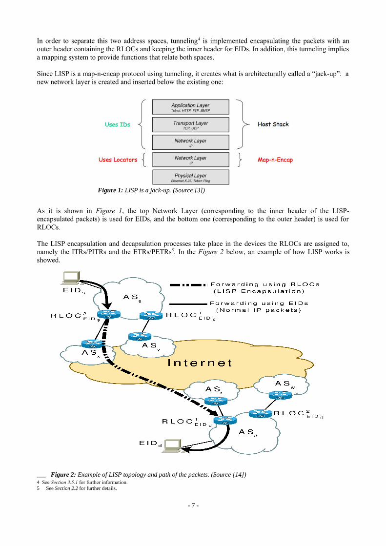
Since LISP is a map-n-encap protocol using tunneling, it creates what is architecturally called a “jack-up”: a new network layer is created and inserted below the existing one:
As it is shown in Figure 1, the top Network Layer (corresponding to the inner header of the LISP-encapsulated packets) is used for EIDs, and the bottom one (corresponding to the outer header) is used for RLOCs.
The LISP encapsulation and decapsulation processes take place in the devices the RLOCs are assigned to, namely the ITRs/PITRs and the ETRs/PETRs5. In the Figure 2 below, an example of how LISP works is showed.
4 See Section 3.5.1 for further information.5 See Section 2.2 for further details.
- 7 -
Figure 1: LISP is a jack-up. (Source [3])
Figure 2: Example of LISP topology and path of the packets. (Source [14])

The end-point devices, identified with EIDs, forward packets to the middle-point LISP routers, identified with RLOCs, where they are LISP-encapsulated and a tunnel is build, in which packets are forwarded through other RLOCs until the RLOC where the destination EID is located. Then, the destination LISP router decapsulates the packets, converting them back into normal IP packets, and forwards them through the EID network until the destination EID device.
2.2. LISP Network Elements
From the tunneling process that LISP performs, two network elements are defined:
• The LISP Egress Tunnel Router (ETR)
This is a router that receives LISP-encapsulated IP packets from the Internet on one side and sends decapsulated IP packets to site end-systems on the other side. In particular, an ETR accepts an IP packet where destination address in the "outer" IP header is one of its own RLOCs, meaning an IP address of the ETR itself.
• The LISP Ingress Tunnel Router (ITR)
This is a router that accepts IP packets from site end-systems on one side and sends LISP-encapsulated IP packets towards the Internet on the other side. In particular, an ITR accepts an IP packet with a single IP header (more precisely, an IP packet that does not contain a LISP header). The router treats this "inner" IP destination address as an EID and performs an EID-to-RLOC mapping lookup if necessary (i.e., it doesn't already have an EID-to-RLOC mapping for the EID). This EID-to-RLOC search is done by means of the LISP Cache, a LISP routing table sitting on the ITR which contains the EID-to-RLOC mappings for destination EIDs which have already communicated with it. In case the LISP Cache doesn't have the mapping for the destination EID, it will be the LISP Mapping System who takes charge of obtaining it on behalf of the ITR.
After obtaining a mapping for the destination EID, the router prepends an "outer" IP header with one of its globally-routable RLOCs (i.e. an IP address of the ITR) in the source address field and the result of the mapping lookup in the destination address field.
- 8 -
Figure 3: LISP tunneling. A Tunnel is created from Router A (ITR) to Router B (ETR).
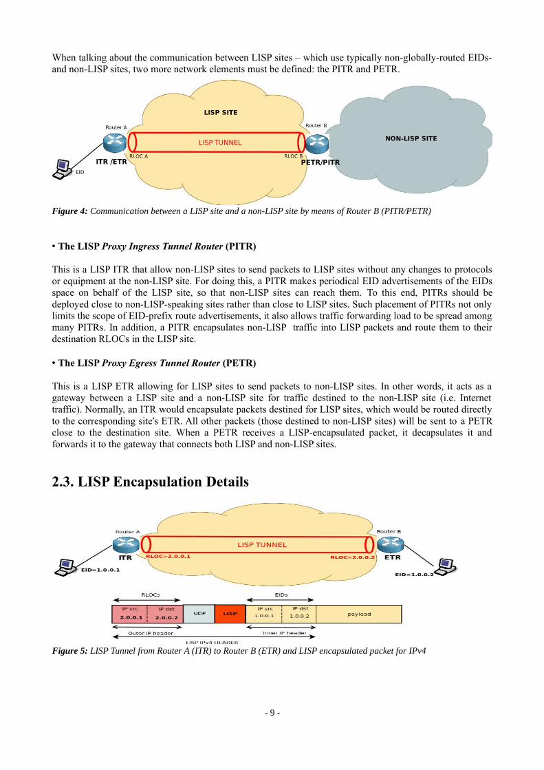
When talking about the communication between LISP sites – which use typically non-globally-routed EIDs- and non-LISP sites, two more network elements must be defined: the PITR and PETR.
• The LISP Proxy Ingress Tunnel Router (PITR)
This is a LISP ITR that allow non-LISP sites to send packets to LISP sites without any changes to protocols or equipment at the non-LISP site. For doing this, a PITR makes periodical EID advertisements of the EIDs space on behalf of the LISP site, so that non-LISP sites can reach them. To this end, PITRs should be deployed close to non-LISP-speaking sites rather than close to LISP sites. Such placement of PITRs not only limits the scope of EID-prefix route advertisements, it also allows traffic forwarding load to be spread among many PITRs. In addition, a PITR encapsulates non-LISP traffic into LISP packets and route them to their destination RLOCs in the LISP site.
• The LISP Proxy Egress Tunnel Router (PETR)
This is a LISP ETR allowing for LISP sites to send packets to non-LISP sites. In other words, it acts as a gateway between a LISP site and a non-LISP site for traffic destined to the non-LISP site (i.e. Internet traffic). Normally, an ITR would encapsulate packets destined for LISP sites, which would be routed directly to the corresponding site's ETR. All other packets (those destined to non-LISP sites) will be sent to a PETR close to the destination site. When a PETR receives a LISP-encapsulated packet, it decapsulates it and forwards it to the gateway that connects both LISP and non-LISP sites.
2.3. LISP Encapsulation Details
- 9 -
Figure 4: Communication between a LISP site and a non-LISP site by means of Router B (PITR/PETR)
Figure 5: LISP Tunnel from Router A (ITR) to Router B (ETR) and LISP encapsulated packet for IPv4

The LISP IETF draft [LISP] specifies how the LISP packets should be encapsulated. What follows is the LISP header format and the description of every field it contains, according to [LISP].
• Inner Header (IH): The inner header is the IP header on the datagram received from the originating host. The source and destination IP addresses are EIDs.
• Outer Header (OH): The outer header is a new IP header perpended by an ITR. The address fields contain RLOCs obtained from the ingress router’s EID-to-RLOC cache. The IP protocol number is "UDP (17)".
• UDP Header: The UDP header contains a ITR selected source port when encapsulating a packet. The destination port must be set to the well-known IANA assigned port value 4341.
• UDP Checksum: The UDP checksum field should be transmitted as zero by an ITR for IPv4. When a packet with a zero UDP checksum is received by an ETR, the ETR must accept the packet for decapsulation. When an ITR transmits a non-zero value for the UDP checksum, it must send a correctly computed value in this field. When an ETR receives a packet with a non-zero UDP checksum, it may choose to verify the checksum value. If it chooses to perform such verification, and the verification fails, the packet must be silently dropped. If the ETR chooses not to perform the verification, or performs the verification successfully, the packet must be accepted for decapsulation.
• UDP Length: The UDP length field is for an IPv4 encapsulated packet, the inner header Total Length plus the UDP and LISP header lengths are used. The UDP header length is 8 bytes.
• N: The N bit is the nonce-present bit. When this bit is set to 1, the low-order 24-bits of the first 32-bits of the LISP header contains a Nonce.
• L: The L bit is the Locator-Status-Bits field enabled bit. When this bit is set to 1, the Locator-Status-Bits in the second 32-bits of the LISP header are in use.
- 10 -
Figure 6: LISP IPv4 in IPv4 Header Format. (Source [LISP])
• E: The E bit is the echo-nonce-request bit. When this bit is set to 1, the N bit must be 1. This bit should be ignored and has no meaning when the N bit is set to 0.
• V: The V bit is the Map-Version present bit. When this bit is set to 1, the N bit must be 0. This bit indicates that the first 4 bytes of the LISP header is encoded as: 0x01.
• I: The bit I is the Instance ID bit. When this bit is set to 1, the Locator Status Bits field is reduced to 8-bits and the high order 24-bits are used as an Instance ID. If the L-bit is set to 0, then the low-order 8-bits are transmitted as zero and ignored on receipt.
• Flags: The flags field is a 3-bit field that is reserved for future flag use. It is set to 0 on transmit and ignored on receipt.
• LISP Locator Status bits: The locator status bits field in the LISP header is set by an ITR to indicate to an ETR the up/down status of the Locators in the source site. Each RLOC in a Map-Reply is assigned an ordinal value from 0 to n-1 (when there are n RLOCs in a mapping entry). The Locator Status Bits are numbered from 0 to n-1 from the least significant bit of field. When a Locator Status Bit is set to 1, the ITR is indicating to the ETR the RLOC associated with the bit ordinal has up status. When a site has multiple EID prefixes which result in multiple mappings (where each could have a different locator-set), the Locator Status Bits setting in an encapsulated packet must reflect the mapping for the EID-prefix that the inner-header source EID address matches.
• LISP Nonce: The LISP Nonce field is a 24-bit value that is randomly generated by an ITR when the N-bit is set to 1. The nonce is also used when the E-bit is set to request the nonce value to be echoed by the other side when packets are returned. When the E-bit is clear but the N-bit is set, a remote ITR is either echoing a previously requested echo-nonce or providing a random nonce.
More details can be found at [LISP].
2.4. EID-to-RLOC Mapping System
The mapping system is one of the most important parts of the LISP protocol, as it provides the association between both the EID and the RLOC spaces. The LISP specification does not define a specific mapping system for the LISP protocol, since it remains an open domain for investigation. At the moment, several kind of mapping systems have been already proposed.
From an architectural point of view there are two possible ways in which a mapping system could supply mapping information. It can either provide individual answers to specific requests (pull), or distribute (push) all the mappings onto listeners.
In pull-based mapping systems, the ITR sends queries to the mapping system every time it needs to contact a remote EID and has no mapping for it. The mapping system then returns a mapping for a prefix that contains this EID. Pull-based mapping systems have thus similarities with today’s DNS. Proposed pull-based mapping systems include LISP+ALT, LISP-CONS, LISP-DHT and LISP-TREE.
In push-based mapping systems, the ITR receives and stores all the mappings for all EID prefixes even if it does not contact them. Push-based mapping systems have thus similarities with today’s BGP. To the best of our knowledge, NERD is the only proposed push-based mapping system.
What follows is a short description of each of the different mapping systems mentioned above.
- 11 -

• LISP+ALT (Alternative Topology): it is a pull-based mapping system distributed as an overlay, whose routes are maintained by the BGP protocol. When an ITR needs a mapping for a specific EID, it sends a Map-Request LISP control packet to a nearby ALT router. This packet will be forwarded through the necessary other ALT routers in the overlay until it reaches the corresponding ETR, the one that has associated the requested EID. This forwarding is made by means of the ALT routing tables. The ETR then generates a Map-Reply, which is directly sent back to the ITR's RLOC, without using the ALT overlay. More details can be found at [ALT].
• LISP-DHT (Distributed Hash Table): it is a hybrid push/pull approach for mapping distribution. It is based on a Distributed Hash Table (DHT). The purpose of LISP-DHT is to distribute EID-to-RLOC mappings through a distributed hash tables infrastructure. LISP-DHT is designed to preserve the locality of the mapping, i.e., the mapping is always stored on the LISP-DHT nodes chosen by the owner of the mapping. When an ITR needs a mapping, it sends a Map-Request through the LISP-DHT overlay with its RLOC as source address. Each node routes the request according to its finger table (a table that associates a next hop to a portion of the Hash space). The Map-Reply is sent then directly to the ITR via its RLOC. More details can be found at [LISPDHT].
• LISP-CONS (Content Overlay Network Service): it is a pull-based hierarchical content distribution system for EID-to-RLOC mappings. It is a generalization of LISP+ALT, which does not use the BGP routing protocol, but adds support for caching in intermediary nodes. More details can be found at [CONS].
• LISP-NERD (Not-so-novel EID to RLOC Database): it is a flat centralized mapping database, using the push-model. Because any change requires a new version of the database to be downloaded by all ITRs, this approach is unlikely to scale to the needs of a future global LISP mapping system. The main advantage of NERD is the absence of cache misses that could degrade traffic performance. More details can be found at [NERD].
• LISP-TREE: a hierarchical pull-based mapping system that has a clear separation between the mappings storage and their discovery. The mappings storage are under the responsibility of ETRs, and their discovery is based on the DNS protocol. The role of the discovery mechanism is to provide a list of ETRs that respond authoritatively for the mappings associated to the queried EID . When a requester needs to obtain a mapping for an EID, it first sends a request to the discovery part that answers with a list containing the locators of the authoritative ETRs for the requested EID. The requester then sends a Map-Request to one of these ETRs and receives a Map-Reply containing a mapping for the identifier. The mappings are provided by the ETR to let them control their traffic by setting the priorities and weights. More details can be found at [1].
2.4.1. The LISP Map-Server Mapping System
The LISP Map-Server is a LISP network infrastructure component that manages the LISP mapping system. In [LISP] it is assumed the existence of a database to store and propagate the EID-to-RLOC mappings by means of the LISP control packets Map-Request, Map-Reply and Map-Register.
The LISP Map-Server develops two kind of operations: it can act either as a Map-Resolver, or as a Map-Server. What follows is the description of both functionalities:
2.4.1.1. The Map-Resolver
When acting as a Map-Resolver, the LISP Map-Server takes charge of dealing with LISP Map-Requests coming from ITRs. After accepting them, quickly determines whether the IP address of the EID requested to map is part of the EID name-space; if it is not, a Negative Map-Reply is immediately returned to the ITR that created the Map-Request. Otherwise, the Map-Resolver finds the appropriate EID-to-RLOC mapping by
- 12 -

consulting its mapping database system, and then, it creates a LISP Map-Reply with the new mapping found and sends it to the ITR that has made the request.
2.4.1.2. The Map-Server
When acting as a Map-Server, the LISP Map-Server learns EID-to-RLOC mappings from authoritative sources (typically, from ETRs). This learning is done by means of LISP Map-Register messages, which are created by ETRs containing the mappings of the EIDs associated to them. When a LISP Map-Register arrives to the Map-Server, the mapping entries are extracted and stored into its mapping database, so that future requesters can be served when acting as a Map-Resolver. A Map-Server may also publish its registrations to the LISP mapping system, in case it is separated from the Map-Server.
Both Map-Resolver and Map-Server functions can be implemented by a single device, as it has been done in this thesis. The implementation is defined in Section 4.3.
For more details on the LISP Map-Server Mapping System see [LISP-MS].
2.4.2. LISP Control Packet Formats
As mentioned previously, the LISP Control UDP-based messages, used to provide EID-to-RLOC mappings to the LISP site, are the Map-Request, the Map-Reply and the Map-Register LISP packets. What follows is a description of the different operations of these control packets and their format.
2.4.2.1. LISP Map-Request
The LISP Map-Request control packet is a packet build by the ITR in order to request for an EID-to-RLOC mapping to the LISP mapping system. When an ITR needs a mapping for an EID, it sends to the Mapping System a Map-Request, putting on its EID-prefix field the destination IP address of the packet which generated a mapping Cache lookup miss. Then the ITR waits for a Map-Reply, and the original packet is dropped. A successful Map-Reply provide mapping information to the ITR, which will be stored in its LISP Cache so that the next packet to the requested EID can have a successful mapping Cache lookup.
- 13 -
Figure 7: LISP Map-Request Message Format (Source [LISP])
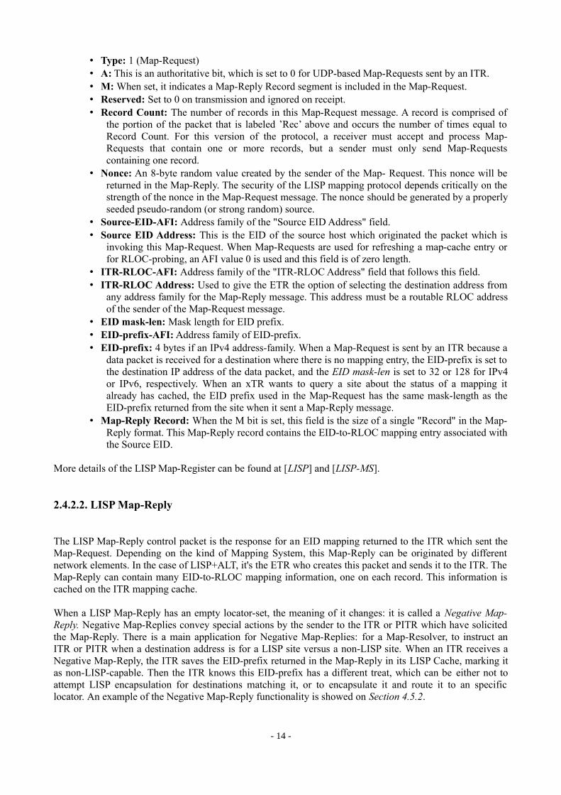
• Type: 1 (Map-Request)• A: This is an authoritative bit, which is set to 0 for UDP-based Map-Requests sent by an ITR.• M: When set, it indicates a Map-Reply Record segment is included in the Map-Request.• Reserved: Set to 0 on transmission and ignored on receipt.• Record Count: The number of records in this Map-Request message. A record is comprised of
the portion of the packet that is labeled ’Rec’ above and occurs the number of times equal to Record Count. For this version of the protocol, a receiver must accept and process Map-Requests that contain one or more records, but a sender must only send Map-Requests containing one record.
• Nonce: An 8-byte random value created by the sender of the Map- Request. This nonce will be returned in the Map-Reply. The security of the LISP mapping protocol depends critically on the strength of the nonce in the Map-Request message. The nonce should be generated by a properly seeded pseudo-random (or strong random) source.
• Source-EID-AFI: Address family of the "Source EID Address" field.• Source EID Address: This is the EID of the source host which originated the packet which is
invoking this Map-Request. When Map-Requests are used for refreshing a map-cache entry or for RLOC-probing, an AFI value 0 is used and this field is of zero length.
• ITR-RLOC-AFI: Address family of the "ITR-RLOC Address" field that follows this field.• ITR-RLOC Address: Used to give the ETR the option of selecting the destination address from
any address family for the Map-Reply message. This address must be a routable RLOC address of the sender of the Map-Request message.
• EID mask-len: Mask length for EID prefix.• EID-prefix-AFI: Address family of EID-prefix.• EID-prefix: 4 bytes if an IPv4 address-family. When a Map-Request is sent by an ITR because a
data packet is received for a destination where there is no mapping entry, the EID-prefix is set to the destination IP address of the data packet, and the EID mask-len is set to 32 or 128 for IPv4 or IPv6, respectively. When an xTR wants to query a site about the status of a mapping it already has cached, the EID prefix used in the Map-Request has the same mask-length as the EID-prefix returned from the site when it sent a Map-Reply message.
• Map-Reply Record: When the M bit is set, this field is the size of a single "Record" in the Map-Reply format. This Map-Reply record contains the EID-to-RLOC mapping entry associated with the Source EID.
More details of the LISP Map-Register can be found at [LISP] and [LISP-MS].
2.4.2.2. LISP Map-Reply
The LISP Map-Reply control packet is the response for an EID mapping returned to the ITR which sent the Map-Request. Depending on the kind of Mapping System, this Map-Reply can be originated by different network elements. In the case of LISP+ALT, it's the ETR who creates this packet and sends it to the ITR. The Map-Reply can contain many EID-to-RLOC mapping information, one on each record. This information is cached on the ITR mapping cache.
When a LISP Map-Reply has an empty locator-set, the meaning of it changes: it is called a Negative Map-Reply. Negative Map-Replies convey special actions by the sender to the ITR or PITR which have solicited the Map-Reply. There is a main application for Negative Map-Replies: for a Map-Resolver, to instruct an ITR or PITR when a destination address is for a LISP site versus a non-LISP site. When an ITR receives a Negative Map-Reply, the ITR saves the EID-prefix returned in the Map-Reply in its LISP Cache, marking it as non-LISP-capable. Then the ITR knows this EID-prefix has a different treat, which can be either not to attempt LISP encapsulation for destinations matching it, or to encapsulate it and route it to an specific locator. An example of the Negative Map-Reply functionality is showed on Section 4.5.2.
- 14 -
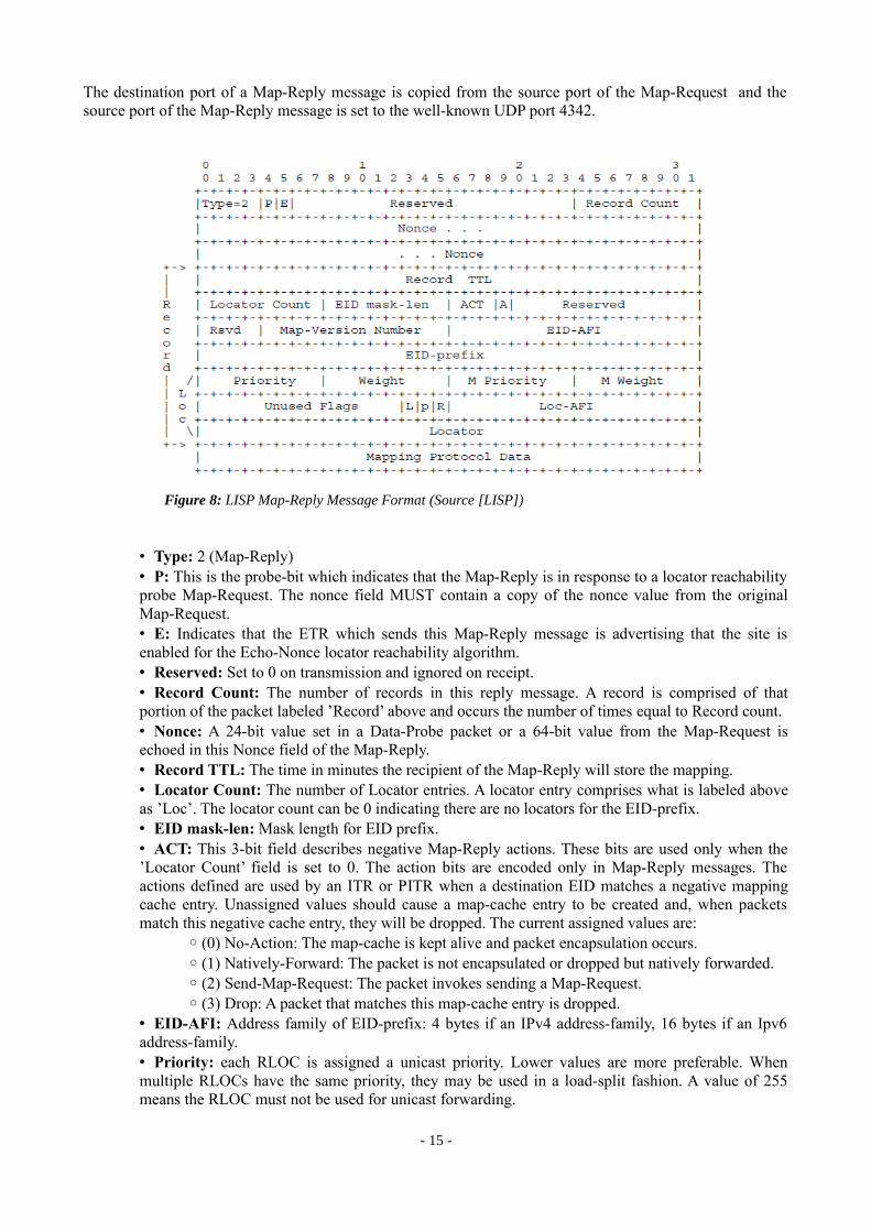
The destination port of a Map-Reply message is copied from the source port of the Map-Request and the source port of the Map-Reply message is set to the well-known UDP port 4342.
• Type: 2 (Map-Reply)• P: This is the probe-bit which indicates that the Map-Reply is in response to a locator reachability probe Map-Request. The nonce field MUST contain a copy of the nonce value from the original Map-Request.• E: Indicates that the ETR which sends this Map-Reply message is advertising that the site is enabled for the Echo-Nonce locator reachability algorithm. • Reserved: Set to 0 on transmission and ignored on receipt.• Record Count: The number of records in this reply message. A record is comprised of that portion of the packet labeled ’Record’ above and occurs the number of times equal to Record count.• Nonce: A 24-bit value set in a Data-Probe packet or a 64-bit value from the Map-Request is echoed in this Nonce field of the Map-Reply.• Record TTL: The time in minutes the recipient of the Map-Reply will store the mapping. • Locator Count: The number of Locator entries. A locator entry comprises what is labeled above as ’Loc’. The locator count can be 0 indicating there are no locators for the EID-prefix.• EID mask-len: Mask length for EID prefix.• ACT: This 3-bit field describes negative Map-Reply actions. These bits are used only when the ’Locator Count’ field is set to 0. The action bits are encoded only in Map-Reply messages. The actions defined are used by an ITR or PITR when a destination EID matches a negative mapping cache entry. Unassigned values should cause a map-cache entry to be created and, when packets match this negative cache entry, they will be dropped. The current assigned values are:
◦ (0) No-Action: The map-cache is kept alive and packet encapsulation occurs.◦ (1) Natively-Forward: The packet is not encapsulated or dropped but natively forwarded.◦ (2) Send-Map-Request: The packet invokes sending a Map-Request.◦ (3) Drop: A packet that matches this map-cache entry is dropped.
• EID-AFI: Address family of EID-prefix: 4 bytes if an IPv4 address-family, 16 bytes if an Ipv6 address-family.• Priority: each RLOC is assigned a unicast priority. Lower values are more preferable. When multiple RLOCs have the same priority, they may be used in a load-split fashion. A value of 255 means the RLOC must not be used for unicast forwarding.
- 15 -
Figure 8: LISP Map-Reply Message Format (Source [LISP])

• Weight: when priorities are the same for multiple RLOCs, the weight indicates how to balance unicast traffic between them. Weight is encoded as a relative weight of total unicast packets that match the mapping entry. If a non-zero weight value is used for any RLOC, then all RLOCs must use a non-zero weight value and then the sum of all weight values MUST equal 100. If a zero value is used for any RLOC weight, then all weights MUST be zero and the receiver of the Map-Reply will decide how to load-split traffic.• L: when this bit is set, the locator is flagged as a local locator to the ETR that is sending the Map-Reply. When a Map-Server is doing proxy Map-Replying for a LISP site, the L bit is set to 0 for all locators in this locator-set.• Locator: an IPv4 or IPv6 address (as encoded by the ’Loc-AFI’ field) assigned to an ETR. Note that the destination RLOC address may be an anycast address. A source RLOC can be an anycast address as well. The source or destination RLOC must not be the broadcast address (255.255.255.255 or any subnet broadcast address known to the router), and must not be a link-local multicast address. The source RLOC must not be a multicast address. The destination RLOC should be a multicast address if it is being mapped from a multicast destination EID.
More details of the LISP Map-Register can be found at [LISP] and [LISP-MS].
2.4.3.3. LISP Map-Register
The LISP Map-Register is a LISP control message sent by an ETR to a Map-Server to register its associated EID-prefixes. The Map-Server stores then these information in its own database, which will be used to send Map-Replies to the ITRs.
A Map-Register message includes authentication data: before sending a Map-Register message, the ETR and Map-Server must be configured with a secret shared-key. A Map-Server’s configuration should also include list of the EID- prefixes for which each ETR is authoritative and should verify that a Map-Register received from an ETR only contain EID-prefixes that are associated with that ETR.
Map-Register messages are sent periodically from an ETR to a Map-Server with a suggested interval between messages of one minute. A Map-Server should time-out and remove an ETR’s registration if it has not received a valid Map-Register message within the past three minutes. When first contacting a Map-Server after restart or changes to its EID-to-RLOC database mappings, an ETR may initially send Map- Register messages at an increased frequency, up to one every 20 seconds. This "quick registration" period is limited to five minutes in duration. Note that a one-minute minimum registration interval during steady state maintenance of an association between an ITR and a Map-Server does set a lower-bound on how quickly and how frequently a mapping database entry can be updated. This may have implications for what sorts of mobility can supported directly by the mapping system, as it will be commented in Chapter 7.
- 16 -

• Type: 3 (Map-Register)• P: This is the proxy-map-reply bit, when set to 1 an ETR sends a Map-Register message requesting for the Map-Server to proxy Map-Reply. The Map-Server will send non-authoritative Map-Replies on behalf of the ETR. • Reserved: Set to 0 on transmission and ignored on receipt.• Record Count: The number of records in this Map-Register message. A record is comprised of that portion of the packet labeled ’Record’ above and occurs the number of times equal to Record count.• Nonce: This 8-byte Nonce field is set to 0 in Map-Register messages.• Key ID: A configured ID to find the configured Message Authentication Code (MAC) algorithm and key value used for the authentication function.• Authentication Data Length: The length in bytes of the Authentication Data field that follows this field. The length of the Authentication Data field is dependent on the Message Authentication Code (MAC) algorithm used. The length field allows a device that doesn’t know the MAC algorithm to correctly parse the packet.• Authentication Data: The message digest used from the output of the Message Authentication Code (MAC) algorithm. The entire Map-Register payload is authenticated with this field preset to 0. After the MAC is computed, it is placed in this field.
More details of the LISP Map-Register can be found at [LISP] and [LISP-MS].
- 17 -
Figure 9: LISP Map-Register Message Format

3. DEPLOYMENT ENVIRONMENT
3.1. Software Tools
In this work, several software tools have been used in order to implement a LISP site. Some of them are software platforms which have been taken as a basis for development, and other are programs which main functionality is to carry out the evaluation part of the implementation. In this section a description of these tools is reported.
3.1.1. The Click Modular Router
Click is a flexible and modular software architecture for building routers. It has been created due to the recent necessity for routers to be not only a way to route packets, but to have also other advanced functionalities, for instance prioritize traffic, translate network addresses, tunnel and filter packets, etc. In this section it is described the Click architecture that can provide easy way of configuring a router, specially why is such a suitable tool for implementing a LISP router.
3.1.1.1. Click Architecture
In order to build a router configuration, Click uses its own programming language for describing a graph where the vertices (called elements) take the role of processing the packets and the edges (called connections) between them represent possible paths the packets can take. In other words, when running a Click configuration a packet might follow a path from elements to other elements, and in each element a different functionality or process can be implemented, such as modifying the packet, filtering or routing it.
● Click Elements
The fundamental unit of a Click graph is called element. The elements are the agents that provide to the router all its functionalities. For example, an element can process packets, modify them, filter them, route them or even create them. All these actions are defined or implemented as C++ objects, and the connections are represented as pointers between them. In addition, the user has the possibility to create its own elements – actually it's what it has been done to implement LISP in this thesis, see Section 4.2.2.1.
Every element is a C++ class, and can have different number of input and output ports. Every connection goes from an output port to an input port of a different element. To have different inputs or outputs can aid the user to separate packets depending on its nature, or on the path the user want them to take.
New elements can also be created in the Click Script itself, by means of other elements: the Compound Elements. In the BOWL Click configuration, they are implemented to create elements that manage the several network interfaces of the node. An example of them is described in Section 3.5.2.1.1.
● Connections
There are two ways a packet can traverse the graph that symbolizes the Click configuration: it can be initiated either by the source end (Push connection) or by the destination end (Pull connection). On a push connection, the packets flow from a source element (witch can be either an element that creates packets, or
- 18 -
that takes them from a non-Click source, such as a network interface or a file), downstream to a destination element (which can be, the same way, either an element that Discard packets or that takes them to a non-Click destination). On a pull connection, instead, it's the destination element who initiates a packet flow; normally, this fact happens because of an expected reply or a packet return that the element is expecting. Thus, these two kind of connections, defined by the ports of the elements between whom they are, mean that all the links are one-way, and two-way links are not allowed.
3.1.1.2. Click Declarative Language
Another advantage of a Click configuration, apart from its easy-looking architecture, is how it is written. Click is programmed in a simple language, where there are only declarations of elements and connections between them. In addition, it exists a way to create new elements using the ones that already exist: the compound elements; it is a way to create element classes but using the Click language.
It's important to point out that Click uses a declarative language, that is, it specifies how is the graph architecturally defined, not how it is executed procedurally.
3.1.1.3. Click for implementing LISP
Click is a very suitable tool for implementing LISP, due to the fact that each LISP functionality can be implemented separately in a Click element. For instance, there are 4 different Click elements (LISPEncapReq, LISPDecap, LISPCache, LISPRegister) which develop several LISP actions: encapsulation, decapsulation, route mapping, and creation and reception of LISP control packets. All these LISP elements are what determinate the behavior of the LISP site, more particularly of each router, and are defined in Section 4.2.2.1.
Since the LISP Data Plane (the map-n-encap operation) and the LISP Control Plane (the EID-to-RLOC mapping system) are very modular – they are defined in the LISP specification step by step-, Click provides the perfect mechanism to implement them in a suitable and modular way.
In addition, implementing LISP in Click provides to the LISP router the main advantage of Click: acting as more than a normal router. That means the router is not only expected to route packets, but to implement a new network protocol such as LISP.
Further details on the Click Modular Router can be found at [9].
3.1.2. OpenWRT
All the nodes in the BOWL testbed run a customized version of the OpenWRT operative system, called Openweed. It is a Linux distribution for embedded devices, with a strong integration of network components. It provides a fully writable file system with packet management that allows the user to customize the device through the use of packages to suit any application; that is why it is a suitable operative system for developers.
More details on OpenWRT can be found at [10].
- 19 -

3.1.3. Measurement Tools
The main measurement tools that have been used in this thesis are described below:
• Tcpdump
This is a common packet capture software. It allows the user to intercept and display all kinds of traffic that pass through a network interface, without considering the direction of the packets (whether they are sent or received). It is a free software that operates on most Unix-like operating systems.
Tcpdump provides the ability to analyze network behavior, performance and applications that generate or receive network traffic. It can also be used for analyzing the network infrastructure itself by determining whether all necessary routing is occurring properly, allowing the user to further isolate the source of a problem.
Between all its possibilities, in order to store the traces received or sent in Chapter 5 on the Access and Mesh interfaces of the access points, tcpdump provides an option used to store capture the traces into cap/pcap files, with the possibility to manipulate them a posteriori. In addition, tcpdumps can report all sorts of the information that the user may need, such as the timestamp, which can be used to calculate magnitudes such as Bandwidth or time delays.
For more information on this tool, see [5].
• Wireshark
This is a free and open-source packet analyzer. It is used for network troubleshooting, analysis, software and communications protocol development, and education. Originally named Ethereal, in May 2006 the project was renamed Wireshark due to trademark issues.
Wireshark is very similar to tcpdump, but has a graphical front-end, and many more information sorting and filtering options (although similar sorting and filtering can be achieved on the command line by combining tcpdump with grep, sort, etc.). Wireshark allows the user to see all traffic being passed over the network (usually an Ethernet network but support is being added for others) by putting the network interface into promiscuous mode.
On this thesis, it has been used to make trace analisys of the pcap captures done by tcpdump, with the additional functionality of plotting traffic flows.
For more information on this tool, see [6].
• Iperf
Iperf is a commonly used network testing tool that can create TCP and UDP data streams and measure the throughput of a network that is carrying them. Iperf is a modern tool for network performance measurement written in C++.
Iperf allows the user to set various parameters that can be used for testing a network, or alternately for optimizing or tuning a network. Iperf has a client and server functionality, and can measure the throughput between the two ends, either unidirectonally or bi-directionally. It is open source software and runs on various platforms including Linux, Unix and Windows. It is supported by the National Laboratory for Applied Network Research.
In this thesis, it has been used to inject to the BOWL Indoor Wireless Network both UDP and TCP traffic in order to perform measurements such as the TCP Throughput or the UDP Bandwidth received. It is important
- 20 -

to point out that the TCP Throughput reported by iperf is the one measured by the payload of the packets (i.e., without header). This fact will be useful in the measurements section of this thesis to relate the TCP Throughput with the LISP packet header.
For more information on this tool, see [7].
• Wget
This is a computer program that retrieves content from web servers, and is part of the GNU Project. It supports downloading via HTTP, HTTPS, and FTP protocols, the most popular TCP/IP-based protocols used for web browsing.
Between all the functionalities it has, in this thesis it has been used to download the Title page of a url into an html file. When using it for this functionality, wget reports the time of downloading it has needed to dowload it.
For more information on this tool, see [8].
3.2. The BOWL Testbed
BOWL (Berlin Open Wireless Lab) is a project of the Intelligent Networks (INET) group at Deutsche Telekom Laboratories. The main goal of the BOWL project is to provide an open research platform for the wireless networking community.
In the whole BOWL testbed, there are 52 operative nodes, and all of them are build around an Avila Gateworks motherboard. Each node has four wireless interfaces and one wired Ethernet connection for accessing and managing them remotely, as well as for powering them on and off, and they run all a customized version of the OpenWRT operative system, a GNU/Linux distribution for embedded devices. BOWL provides three different Wireless Mesh Networks:
3.2.1. The Smoketest Network
This is the smallest testbed. It has 8 nodes, located on one room the 15 th floor of the Telefunken building. The main usability of this network is to do a first test or proof before using the other two testbeds. Before running experiments in the Indoor or Outdoor networks, everything should be tested in Smoketest. In the case of LISP, it has been deployed in this network by using specials Click configurations, for instance the Local traffic configuration, which allows having several fake clients by creating fake tap interfaces on every node, and bridging them to the wired interface, so that a Virtual Machine located in Panther6 simulates a fake client end-point host.
Another use of Smoketest is, as it has been done for LISP, to use its nodes as end-host fix clients, and attaching them to the Access Wireless Network interface of the Indoor nodes.
6 This the BOWL Central Server. It takes charge of giving access via ssh to all the BOWL nodes (over wire), as well as containing the Node-Manager and all the BOWL repositories that have the code running in all the infrastructure.
- 21 -

3.2.2. The Indoor Network
This is the second testbed, a 9 node wireless network located between the 16 th and 17th floors of the Telefunken building. This network is, the same way, a test-network for bigger experiments planed to be deployed Outdoor.
This network is the main environment where LISP has been tested and where have been taken the LISP measurements for the goal of this thesis. For more information see Chapter 4 and Chapter 5.
The main goal of the Indoor testbed is to achieve a compromise between a reliable Internet access for users and a network programmability for researchers. In this thesis, no LISP experiments have been deployed using Outdoor, considering the fact that the Indoor testbed provides already the suitable environment to implement LISP and reach the objectives proposed.
3.2.3. The Outdoor Network
The BOWL project maintains a reconfigurable wireless outdoor testbed with 42 nodes. The network can be configured to serve as both an infrastructure and a mesh network. This testbed is integrated to TU-Berlin's IT department (tubIT) and its infrastructure for student access. As it is used also in the main university for giving wireless Internet access to real users, behind this network there is a solid system to avoid failures or
- 22 -
Figure 10: BOWL Smoketest Wireless Network
Figure 11: BOWL Indoor Wireless Network (Source [12])
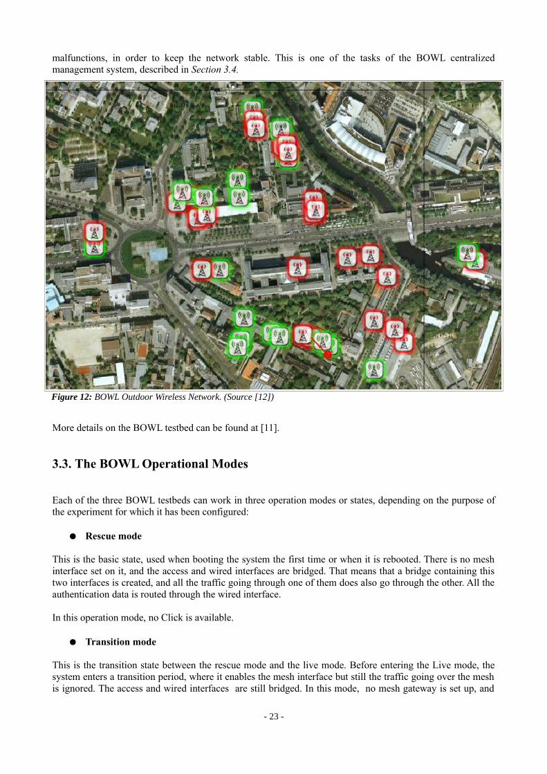
malfunctions, in order to keep the network stable. This is one of the tasks of the BOWL centralized management system, described in Section 3.4.
More details on the BOWL testbed can be found at [11].
3.3. The BOWL Operational Modes
Each of the three BOWL testbeds can work in three operation modes or states, depending on the purpose of the experiment for which it has been configured:
● Rescue mode
This is the basic state, used when booting the system the first time or when it is rebooted. There is no mesh interface set on it, and the access and wired interfaces are bridged. That means that a bridge containing this two interfaces is created, and all the traffic going through one of them does also go through the other. All the authentication data is routed through the wired interface.
In this operation mode, no Click is available.
● Transition mode
This is the transition state between the rescue mode and the live mode. Before entering the Live mode, the system enters a transition period, where it enables the mesh interface but still the traffic going over the mesh is ignored. The access and wired interfaces are still bridged. In this mode, no mesh gateway is set up, and
- 23 -
Figure 12: BOWL Outdoor Wireless Network. (Source [12])
thus Internet traffic is not available. This transitional state is used to prepare the node before the Live mode, and make sure that everything is set up.
● Live mode
This is the system ready to use Internet traffic going via the Mesh gateway to the Internet. On it, the Access and Wired interfaces are not bridged any more, because each interface has to deal with different kind of traffic separately. Hence, the 802.1x Authentication protocol is not supported. See Section 4.4.1 for further information.
More details can be found at [11].
Interaction between bridging and Click:
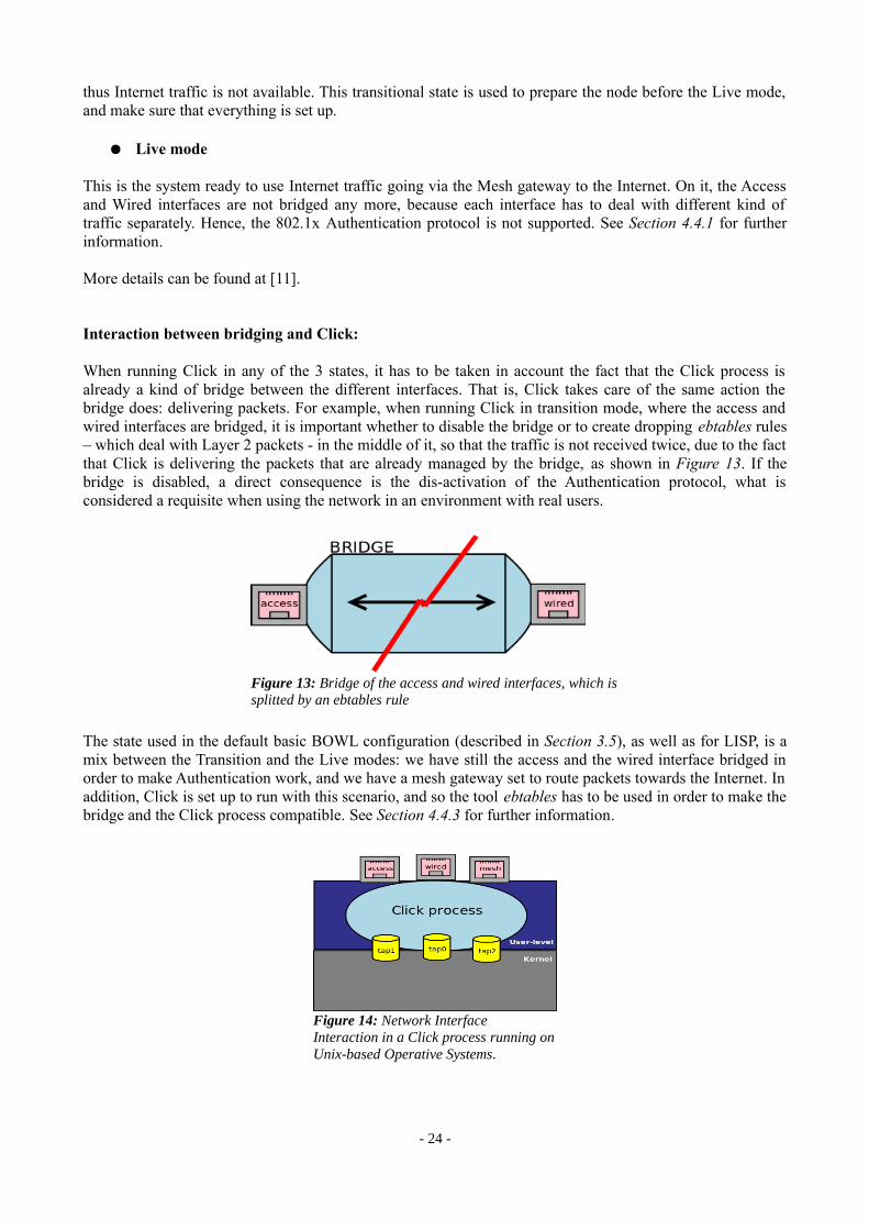
When running Click in any of the 3 states, it has to be taken in account the fact that the Click process is already a kind of bridge between the different interfaces. That is, Click takes care of the same action the bridge does: delivering packets. For example, when running Click in transition mode, where the access and wired interfaces are bridged, it is important whether to disable the bridge or to create dropping ebtables rules – which deal with Layer 2 packets - in the middle of it, so that the traffic is not received twice, due to the fact that Click is delivering the packets that are already managed by the bridge, as shown in Figure 13. If the bridge is disabled, a direct consequence is the dis-activation of the Authentication protocol, what is considered a requisite when using the network in an environment with real users.
The state used in the default basic BOWL configuration (described in Section 3.5), as well as for LISP, is a mix between the Transition and the Live modes: we have still the access and the wired interface bridged in order to make Authentication work, and we have a mesh gateway set to route packets towards the Internet. In addition, Click is set up to run with this scenario, and so the tool ebtables has to be used in order to make the bridge and the Click process compatible. See Section 4.4.3 for further information.
- 24 -
Figure 13: Bridge of the access and wired interfaces, which is splitted by an ebtables rule
Figure 14: Network Interface Interaction in a Click process running on Unix-based Operative Systems.

As shown in Figure 14, the Click process, which is running on the User-level of the operative system, deals with the real network interfaces (access, wired and mesh), and the Kernel of the Operative System with the fake (tap) interfaces, which are created by Click. Each tap interface represents one of the 3 real interfaces, and the Click process forwards the packets from the real interfaces to their corresponding tap interface in case they need to reach the Kernel. An example of this are the ICMP packets, which are queried/responded by the Operative System and thus Click forwards them from the real interfaces to the fake ones and vice-versa.
The Click configuration which creates the fake interfaces is described in Section 3.5.2.
3.4. The BOWL Management Architecture
The BOWL testbed needs to have a centralized actor that monitors its components and helps in their management. This management action is done by 2 agents: the Node Manager, a central server which monitors the network, and the Node Controller, a process running on each node allowing the communication between the Node Manager and them.
3.4.1. The Node Manager
The Node Manager is the BOWL central management unit. It handles the whole BOWL testbed (it can manage the Smoketest, Indoor or Outdoor networks), by keeping all the information and state of the nodes and communicating with them. This is done by two main components:
• The BOWL database (bowldb): a database back-end that maintains the nodes' state and information, in order to distribute the information to control the nodes in a centralized way.
• The callback framework: a framework allowing the communication between the manager and the controllers. It is based about giving instructions to the nodes or executing functions that can be run upon certain actions already initiated by the Node Controller. Since all the functions that the Node Controller executes are implemented in Ruby, the communication between the manager and them is marshaled by using druby, a tool that allows for information and code distribution to the nodes.
The Node Manager and its database is located on panther, the central server of the BOWL infrastructure, which allows access over wire to all its components. Figure 15 shows the interaction between the Node Manager and the Node Controller by means of Callbacks.
- 25 -
Figure 15: Node-Manager Callbacks. The Node Controller process send Callbacks to the Node Manager, which update its database (bowldb), and send Callbacks back to the node when requested.

Another functionality of the Node Manager is the ability of either importing current configurations to the nodes or exporting configurations from them. This is done by a web front-end user interface, which allow having stored different user UCI7 configurations and manage all the BOWL nodes in a quick and easy way. Every UCI configuration loaded on the node can manage either the network interfaces configuration, the node-controller configuration (of its Adaptors and other tools), the DHCP set up, or all what is configurable on the node (see Figure 16). The web front-end user interface has also the ability of exporting files, useful for loading Click configurations into the nodes.
3.4.2. The Node Controller
The Node Controller is a software running on every node which executes commands initiated by the Node Manager and collects state information (i.e., to make measurements or control the condition of the network). This software, written in Ruby, is deployed on different threads or programs (called Adaptors) which control each a different functionality (e.g., DHCP, Click, OLSRD, etc) in the node, control daemons and relay information to the Node Controller itself.
The state of an Adaptor is relayed to the Node Manager using events, and this information is stored in the BOWL database. This process may originate callbacks back to the nodes to maintain the stability of the network. From all the Adaptors the Node Controller deploy, this thesis focuses on the one that manages the Click process on each node. In order to implement LISP, this process has been modified so that the LISP mapping system is updated when running Click. This process is described in Section 4.4.1.
3.5. The BOWL Basic Configuration
The BOWL testbed has a default basic configuration set up, which has been created by the BOWL group in order to provide stability and correct functioning in Wireless Mesh Networks. This set up consists of a mesh testbed using mesh tunneling through the IPIP protocol, which is implemented using Click. Part of this configuration has been used in this thesis to implement LISP, and one of its goals is the comparison between
7 UCI (Unified Configuration Interface) is a centralized configuration for OpenWRT systems. It makes easy to import and export network configurations to the different devices.
- 26 -
Figure 16: UCI configuration process managed by the Node Manager. The user can set up his own centralized UCI configuration, which is imported to the nodes in an easy way.

both LISP and IPIP protocols. In this section, an example of this IPIP basic configuration is described, as well as the Click configuration that implements it.
3.5.1. The IP-in-IP protocol
The IP-in-IP protocol, also called IPIP, is the result of the necessity of tunneling performance. It consists on adding an extra IP header to the IP packets (IP within IP encapsulation), which will contain the tunneling information.
Generally, a Tunneling protocol is a network protocol which encapsulates a different payload protocol. A tunnel is defined by an Ingress Tunnel Router (ITR) and a Egress Tunnel Router (ETR), which are its two end-points. Between them, the packets do not care about the path/way they follow until the ETR, and even they can traverse different networks. In the case of IPIP, the outer header has the information of both ITR and ETR, storing their IP addresses in the source and destination fields, and the original IP packet is, in the IPIP encapsulated packet, its payload (see figure).
In the BOWL testbed, IP over IP is used to tunnel packets over the mesh. Packets that traverse the mesh interface have two IP headers, and every ETR takes care of stripping the outer IP header of every packet when it is received from the mesh. This configuration, currently the basic set up of BOWL, is very similar to the LISP one, in the sense that both use tunneling for sending packets over the mesh. In this thesis, both IPIP and LISP protocols are compared in Chapter 6.
3.5.2. IP-in-IP Click Configuration
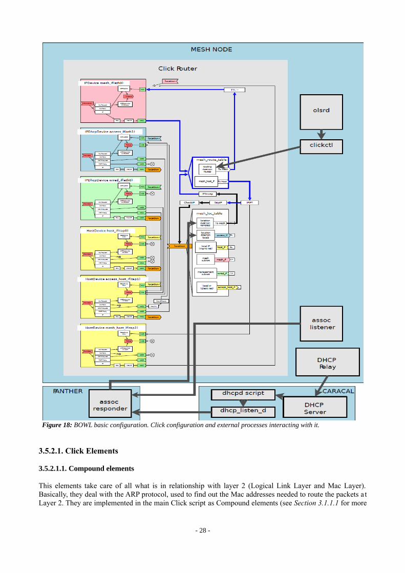
The basic IP-in-IP BOWL mesh configuration is set up by means of Click (see Section 3.1.1 for more information). The following figure is a representation of how the Click configuration, run on every mesh node, takes care of its interfaces (Access, Mesh and Wired), as well as the routing table and the IPIP tunneling, and how the other agents in the node interact with it.
- 27 -
Figure 17: IPIP Tunneling and encapsulation
3.5.2.1. Click Elements
3.5.2.1.1. Compound elements
This elements take care of all what is in relationship with layer 2 (Logical Link Layer and Mac Layer). Basically, they deal with the ARP protocol, used to find out the Mac addresses needed to route the packets a t Layer 2. They are implemented in the main Click script as Compound elements (see Section 3.1.1.1 for more
- 28 -
Figure 18: BOWL basic configuration. Click configuration and external processes interacting with it.

information), and there are two kind of elements:
● IPDevice
Used to manage the real interface devices. This element, implemented as a Click compound element, takes care of the Ethernet header of the packets, dealing entirely with the ARP protocol. It has an ARP Querier and an ARP Responder. It also forwards broadcast, DHCP, IP and unicast traffic.
Three interfaces are managed by the IPDevice compound element:
• wired_if (eth0): This is the network interface of the node connected to the wire. All the traffic exchanged with panther and with the node-manager, as well as the Internet traffic on the mesh gateway, go through this interface.
• access_if (access0): This is the wireless network interface where the clients attach to.
• mesh_if (mesh0): This is the wireless network interface that connects the nodes in the mesh network.
● HostDevice
Used to create a virtual interface (tap interface). This interface make a connection between the Click process and the Kernel of the operative system; more information can be found in Section 3.3. The tap interfaces take care as well of the Ethernet layer, providing to the packets the suitable Ethernet header obtained through the ARP protocol.
Three interfaces are managed by the HostDevice compound element:
• host_if (tap0): Virtual or tap interface corresponding to the wired interface eth0 for the Kernel of the operative system. It has assigned the same IP address as the wired_if interface (eth0).
• access_host_if (tap1): virtual or tap interface corresponding to the access interface access0 for the Kernel of the operative system. It has assigned the same IP address as the access_if interface (access0).
• mesh_host_if (tap2): Virtual or tap interface corresponding to the mesh interface mesh0 for the Kernel of the operative system. It has assigned the same IP address as the mesh_if interface (mesh0).
3.5.2.1.2. Routing Tables
• The Mesh Routing Table (mesh_route_table element)
This is the routing table for the mesh incoming and outgoing traffic. That means before a mesh packet leaves the click process, it is sent thanks to this routing table to the mesh_if interface. The same way, a packet that comes from the mesh through the mesh_if interface, depending on its destination or its protocol, it is routed whether to other Click elements or directly to another interface.
What's more, the routes to the mesh of this routing table are updated dynamically by a process called olsrd, described below.
• The Mesh Location Table (mesh_loc_table element)
This is the routing table for IP packets which routes the packets whether to the mesh – and so to the IP encapsulation element, or to any of the other interfaces. It reads the inner IP header (before encapsulation or
- 29 -

after striping the outer header) of the packets. The two first outputs, that forward packets to the mesh or the access interfaces respectively, are as well constantly updated by the Node Controller, using the Click User Adaptor. The mesh_location_table takes care of the system's Routing protocol: when an IP packet is received through the access interface (in the figure called access_if), if its destination IP address is from a remote client attached to another node, the packet is routed by the mesh_location_table to the IPEncap element. The mesh_location_table knows to which node the packet has to be sent over the mesh thanks to the Click Adaptor process, which updates the routing table by means of callbacks. The packet is then encapsulated in an outer IP header with its destination IP address set as the IP address of the mesh node where the remote client is attached. If the original packet has the destination IP address from a local client – that means a client attached to the same node-, the mesh_loc_table routes it to the access interface using the information of the routing table.
The Click Adaptor process that updates the mesh_location_table, is run by the Node Controller, which at the same time communicates with the Node Manager, and thus the mesh_location_table has the information of where all the clients of the network are located – what means, on which nodes are attached. In this thesis, the Click Adaptor process has been modified so that it supports LISP-Click configuration, as it is described in Section 4.4.1.
A few part of this Click configuration has been used in this thesis to implement LISP. For instance, the elements HostDevice and IPDevice created to manage the different interfaces are the same as the ones used in the LISP-Click configuration described in Section 4.2.
3.5.2.2. Other Components
Other actors external from Click that play a role in this configuration are:
• DHCP server: this server, located in Caracal, manages the DHCP client system of the mesh nodes. All the DHCP information travels through wire, except the dhcp requests and replies necessaries between the clients and the access points in order for them to associate. .
• Olsrd: a Deamon that listens around to the different wireless network devices in order to provide alternative routes to them in case of bad wireless connectivity. This process is managed by the Node Manager through the Olsrd Adaptor process running on every node. This process adds and deletes routes to the mesh network, and so the routing table reads the destination IP address of the outer IP header of the packet (which has been IPIP-encapsulated) and routes it through the interface – called mesh_if in Figure 18.
• Assoc Manager: a process running on each node taking charge of dealing with association packets from the clients in order to attach them to the Access Points. There is an assoc listener, which listens for clients, and an assoc responder, which manages the assoc replies. When a client has visible access point, he broadcasts association requests packets to the Access Points in order to associate to them, and he connects to them as soon as an association reply from one of the Access Points is received. If the Access subnetwork is doted with the radius authentication 802.1x protocol, a verification for the client credentials is done within the Association process.
- 30 -

4. LISP IMPLEMENTATION
This chapter describes how LISP is implemented in the particular Bowl Indoor Network. It includes not only the LISP scenario used, but also the configuration run in each node necessary for having a real LISP site, supporting all kinds of traffic.
The network used to test LISP is the BOWL Indoor Network. Each node acts as a LISP-Click router Access Point. All the nodes are running the same Click configuration, that is a Click Script which allows the node to have all LISP abilities.
Each node sets up two wireless interfaces, one called mesh0, which creates the Mesh Network, and the other called access0, which creates the Access Network, allowing the clients to connect to the nodes or access points. Also, one of the 9 nodes has attached on its wired interface a gateway for the Internet traffic.
4.1. LISP Implemented Features
One of the goals of this thesis is to reproduce a real LISP site, following all the aspects of its protocol's specification. Though, the LISP specification is actually so extended that only some aspects of it are implemented. What's more, not all the LISP functionalities are specified; some domains, like the LISP Mapping System, remains an open branch for further investigation and new proposals. The specification of the LISP protocol that has been taken as a reference in this particular experiment is the [LISP], [LISP-MS], and [INTERWORK].
● LISP main draft [LISP]:
From the main [LISP] specification draft, it is taken in account all what is in relationship with the EID-RLOC network infrastructure, the LISP header format, the LISP control packets format, the LISP UDP ports and the LISP caching system. More information can be found at Chapter 2.
About the LISP caching system in each of the routers of the network, it is implemented in two separate databases (LISP DB and LISP CACHE), the first taking care of the local clients mapping – that is, the clients attached to the ITRs/PITRs- and the second of the remote clients mapping – that is, the clients attached to the ETRs/PETRs. What's more, it is used a count-down timer system for all the LISP CACHE mapping entries, in order to avoid wrong mappings when the clients roam from an Access Point to another. Note that this is a key point when implementing LISP in wireless networks, because it allows mobility. An example of how the LISP system deploys roaming can be found in Section 4.5.3.
Also, it is considered that the LISP site is unique and isolated: it won't have any communication with any other LISP site, what implies that the LISP encapsulated packets flowing in the LISP site will have one LISP header at maximum.
Concerning the tunneling process, a fundamental point in LISP, it is followed the First-hop/Last-hop Tunnel Routers specification, where it is assumed that the tunnel routers are close to client hosts (actually in the same network space). In addition, the network is configured to support any number of hops between the Ingress Tunnel and the Egress Tunnel.
- 31 -

However, it is not considered the MTU LISP specification when dealing with large encapsulated packets , nor the segmentation of them. It is neither taken in account the mobility of the LISP sites, that means the infrastructure of the network used is fix and won't change its topology.
● LISP Map Server draft [LISP-MS]
In this thesis, it has been used a variation of the Mapping System specified in [LISP-MS]. That means the kind of mapping system implemented in this experiment follows the [LISP-MS] draft in mostly all of its specification, but with some variations. It is assumed the existence of a centralized database, accessible for all the nodes of the network infrastructure, which stores the mapping information of all the EIDs in the LISP site. This mapping system has been implemented in a single device, acting simultaneously as a Map-Server and a Map-Resolver, both described in Section 2.4.1.
What's more, the Negative Map-Reply process is implemented, in case the LISP database doesn't have a mapping for a particular EID. This implies that an ETR/PETR will never send LISP Map-Reply control packets – the Map-Server will take care entirely of this affair-, and that, when acting as Map-Resolver, it will not forward any LISP Map-Request control packet – all Map-Requests will be handled by the LISP Map-Server. Finally, the LISP Mapping System implemented in this thesis will never receive Map-Replies. An example of this process can be found in Section 4.5.2.
Finally, when acting as a Map-Server, it is considered that no authentication is implemented in the LISP Map-Register messages. Thus, it is supposed that no Map-Register packets will have corrupted or malicious data, leaving aside the fact that it is not the goal of this project to take care of security issues.
● LISP Interworking draft [INTERWORK]
This draft is considered as a solution when applying Internet traffic (Internet traffic) in the LISP site. It specifies the protocol followed to inter-operate between a LISP site and a non-LISP site, in particular the use of LISP Proxy Ingress Tunnel Routers (PITRs) and LISP Proxy Egress Tunnel Routers (PETRs). See Section 2.2. for further information.
In the LISP site build in this approach, there is only one router/node who acts at the same time as both PITR and PETR: the mesh gateway node.
In the first case, when acting as a PITR, the gateway node is configured to LISP-encapsulate non-LISP Internet traffic into LISP packets and route them towards their destination RLOCs inside the mesh. Considering the LISP-Click configuration used, the element who takes care of giving the node this behavior is the LISPEncapReq element, described in Section 4.2.2.1. However, it is not taken in account neither the PITR EID Announcements a PITR should make, nor the way the Internet traffic manages to arrive to the LISP site.
In the second case, when acting as a PETR, the gateway node is set up to decapsulate LISP packets and to forward them via gateway to the Internet. More specifically, the packets that arrive to the PETR are sent from ITRs that have matched a negative entry in its CACHE for its destination EID. As in the PITR implementation, the LISPEncapReq element in the LISP-Click configuration cares also about this functionality.
- 32 -
4.2. LISP-Click Architecture
The LISP-Click configuration described in this section has been used in the BOWL Indoor Network to provide the LISP functionality in the site.
There are two factors that have inspirate the LISP-Click architecture implemented:
Firstly, since the LISP implementation runs on the BOWL testbed, some features of the basic IPIP BOWL configuration have been used. More particulary, the Click Compound Elements that manage the different real and virtual interfaces have been used in order to handle the Data Link Layer (Layer 2) of the traffic that passes through these network interfaces; these elements take care of encapsulating and stripping the Ethernet header of the packets. Since the LISP protocol works at the Network Layer (Layer 3) and doesn't make any influence at Layer 2, exactly the same Compound Elements that the IPIP-Click configuration implements have been added in the LISP-Click configuration, which are the IPDevice and the HostDevice elements for the real and virtual interfaces respectively. Also, the LISP-Click configuration has been created using the IPIP-Click architecture: it has also the mesh_route_table element, a routing table which deals with LISP-encapsulated packets, and a mesh_loc_table routing table. In the LISP configuration, though, the mesh_loc_table has only static routes, since the information needed to encapsulate the packets into the LISP header is not stored any more in it, but in in the LISPCache element (see Section 4.2.2.1), where the LISP-DB and LISP-CACHE sit.
Secondly, the implementation of the LISP-Click elements, written in C++, has been done taking as a departure point the basic implementation done by Damien Saucez, a PhD student from the University Catholique de Louvain (Belgium). Basically, D. Saucez did a basic implementation of LISP, done also in Click and which takes care of the LISP encapsulation and decapsulation by using as well different Click elements for handling every LISP functionality separately. However, the LISP elements implemented in this thesis, and together with the LISP Map Server implementation, take care entirely of the LISP Control Plane and LISP Mapping System. Also, the LISP encapsulation performed in the LISPEncapReq element is a result of an elaborated algorithm that takes in account different factors before the encapsulation itself is performed (i.e., the different kind of traffic that can pass through the routers), as it is described in Section 4.2.2.1. What really has been an inspiration point from the D. Saucez implementation is the fact of splitting the different LISP functionalities (i.e., encapsulation, decapsulation and mapping system) into different Click elements, so that each one of them performs a different functionality. More details of the D. Saucez implementation can be found in [13].
On this LISP-Click script, three different kind of Click elements are used: the LISP elements, the routing tables (described in Section 4.2.2) and the compound elements that manage the different network interfaces (described in Section 3.5.2.1.1).
- 33 -
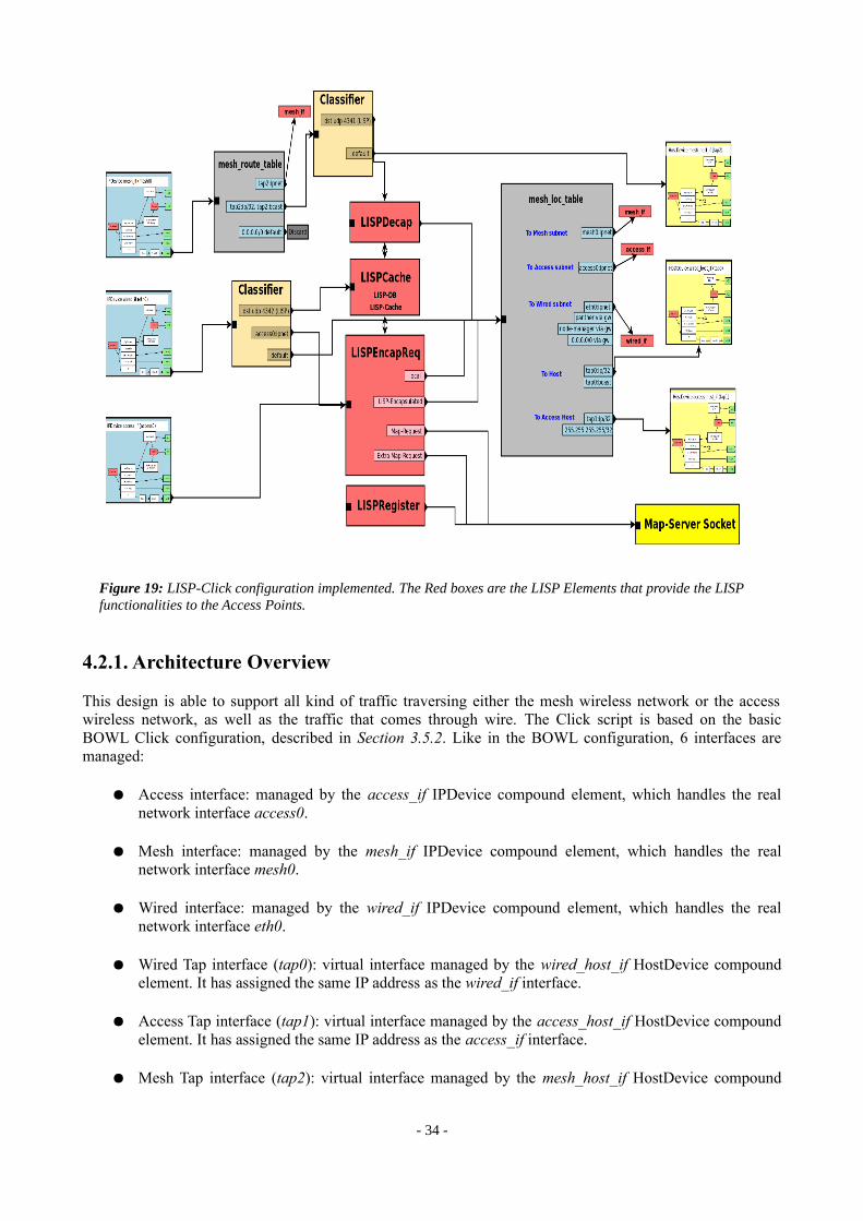
4.2.1. Architecture Overview
This design is able to support all kind of traffic traversing either the mesh wireless network or the access wireless network, as well as the traffic that comes through wire. The Click script is based on the basic BOWL Click configuration, described in Section 3.5.2. Like in the BOWL configuration, 6 interfaces are managed:
● Access interface: managed by the access_if IPDevice compound element, which handles the real network interface access0.
● Mesh interface: managed by the mesh_if IPDevice compound element, which handles the real network interface mesh0.
● Wired interface: managed by the wired_if IPDevice compound element, which handles the real network interface eth0.
● Wired Tap interface (tap0): virtual interface managed by the wired_host_if HostDevice compound element. It has assigned the same IP address as the wired_if interface.
● Access Tap interface (tap1): virtual interface managed by the access_host_if HostDevice compound element. It has assigned the same IP address as the access_if interface.
● Mesh Tap interface (tap2): virtual interface managed by the mesh_host_if HostDevice compound
- 34 -
Figure 19: LISP-Click configuration implemented. The Red boxes are the LISP Elements that provide the LISP functionalities to the Access Points.

element. It has assigned the same IP address as the mesh_if interface.
As we can see in Figure 19, the different kind of Click elements are connected in order to separate several kind of traffic coming from the different interfaces, and they drive it to the mesh location table, a routing table that is in charge to forward the packets to its corresponding interface. In addition, there is also a UDP socket that opens a client connection with the Map Server, in this experiment working always over wire.
The main difference between this Click configuration and the basic BOWL one is the implementation of the LISP elements, the ones that provide the LISP functionality to the system. What's more, both configurations have a mesh location table and a mesh route table. The purpose of both routing tables is the same in both configurations, but they have differences in their routes.
4.2.2. Click Elements Used
4.2.2.1. LISP-Click Elements
The LISP elements are Click elements that have been implemented to manage the LISP functionality of every node. They also take care of Layer 3 (Network) and 4 (Transport). There are 5 different elements:
● LISPCache
This element is responsible for managing all the mapping information, as well as the other LISP elements. It has basically 3 functionalities :
LISP DB and CACHE
It stores both the DB (for local clients, that is for clients attached in the source node or ITR) and the CACHE (for remote clients, that is for clients attached to the destination node or ETR). What follows is an explanation of how these tables are implemented and its characteristics.
DB and CACHE are two objects implemented by the same C++ structure. This implementation uses a radix tree, a kind of database which makes faster the search of one of its entries (in this case, one of its nodes). Each entry/node is a entry of the routing table, and stores different kind of information, which basically is:
• The EID prefix (which includes an IP address and a netmask).• The RLOC(s) the EID prefix is attached to.• The information of the RLOC(s): reachability, nonce info, etc.• The possibility to flag the entry as “Negative”. A negative entry is the result of the database
update of the information coming from a Negative Map Reply. That is, the EID prefixes the Map Server doesn't have any information, they are introduced in the CACHE as negative entries (with any RLOC associated), so that the ITR knows that the packets with this destination IP address should be encapsulated via Internet (with the RLOCDST set to RLOC_GW), because they probably have an Internet server IP address. See Section 2.4.2.2 for further information.
• A timer object, used only for the LISP CACHE, which is reset when a RLOC is added to an EID prefix. When this timer reaches a TIMEOUT time, the entry is removed. To timeout the routing table entries has a mobility reason: a remote client may change his mapping, specially in a wireless network, because he is able to move and change the Access Point where he is attached.
- 35 -

Every time the timeout expires and the entry for a particular EID is removed, an ITR/PITR trying to encapsulate a packet with the same destination EID will need to create a Map-Request again, in order to find out the destination RLOC necessary for the encapsulation. In addition, every time a LISP Map-Reply is received with an EID-to-RLOC mapping and the CACHE is updated, the TIMEOUT is reset.
Note that this parameter can be determining when testing the LISP site; in fact, different measurements have been taken for different values of the CACHE Timeout, depending on the kind of traffic injected to the LISP site (see Chapter 5 for further information).
• A second timer object, only used for the LISP CACHE, which times the period of time spent since the last use of the CACHE entry. Thus, it is reset every time the CACHE entry corresponding to a particular EID is used. This parameter is used in the LISPEncapReq element (see below).
Reception of a LISP Control packet
When a LISP control packet is received in the node (in our case a LISP Map Reply), this element takes charge of extracting its information and updating the CACHE database.
Basically, it double-checks by reading at the LISP Type field of the LISP control packet whether it is a Map-Reply (Type=2). Also, it checks whether it's a Negative Map Reply or not, and reads the EID and RLOC fields of the packet, which are inserted then as new entries in the CACHE. Other fields are also updated, for instance the RLOC information.
Element Handlers
This element allows also to insert, update or delete the information of its databases through an external process. This is the usability of the Click handlers, described in Section 3.1.1. For instance, it is possible to insert, delete or update a DB or CACHE entry information manually, either by calling to these functions in a Click script or in another external process which can speak with Click. In addition, it is possible to change the CACHE Timeout value and to print both the CACHE and DB tables.
This element has one input, used to receive LISP control packets (Map-Replies), and no outputs.
● LISPEncapReq
This element is the one which handles the LISP protocol in the sender side of the network, typically acting on an ITR/PITR. It basically manages two LISP functionalities: encapsulating packets in LISP IPv4 header and creating LISP Map-Request control packets.
Firstly, this element takes care of LISP encapsulation. All traffic that goes to the Mesh needs to be encapsulated in a LISP header. However, some rules have been implemented in an algorithm (see Source 1) to decide what would be the characteristics of the encapsulation, depending on the traffic injected on its input; here is where the node's behavior in a LISP point of view is defined. For instance, considering the [INTERWORK] specification implemented, we have to distinguish two kind of nodes in the mesh network: the simple nodes with client attached to, and the ones that have, in addition, an Internet gateway attached through wire (we consider only one node of this characteristics, which has the functionality of PITR and PETR at the same time). So, the ability of this element is not only encapsulating, but deciding whether to
- 36 -

encapsulate or not, and even to route packets which do not need to go through the mesh but to the access network.
Secondly, this element is also responsible for handling the Control Plane operation: it creates, when necessary, LISP Map-Request control packets and forwards them to the Map-Server via Socket. There are two ways a Map-Request can be sent:
1. When a ITR/PITR needs a Mapping for a remote EID, it looks for it into the LISP CACHE. If the search fails – that means the CACHE entry for this particular EID doesn't exist, a Map-Request for this EID is created and forwarded via Socket to the Map-Server. Then the original packet is dropped. Note that a CACHE entry that has wasted its Timeout will yield as well into a CACHE search failure, and then the process will be the same.
2. Before the ITR/PITR encapsulates a packet – that means the CACHE entry for the destination EID already exists, the ITR/PITR checks when the same CACHE entry has been used the last time. If last time used is more than one second, the packet is also encapsulated with the destination RLOC mapped in the CACHE and sent over the Mesh, and an additional Map-Request is created in the meanwhile and forwarded to the LISP Map-Server via Socket. This process is implemented in order to make packets very separate on time not to be dropped when the CACHE Timeout is over, and since now will be called the LISP Extra-Map-Request mechanism. This process has been implemented after coming up a problem that appeared taking measurements, more particularly when injecting TCP traffic in the LISP site in the mobility scenario: in a TCP client disconnection due to roaming, this process makes the TCP Retransmission packets not to be dropped; see Section 5.1.2.1.1 for an example of this implementation.
The following pseudo-code algorithm implemented shows how the LISPEncapReq element decides how to deal with packets arriving from the access interface, which are forwarded to the LISPEncapReq input (see Figure 19):
- 37 -
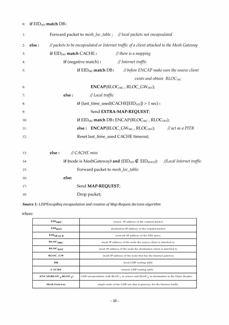
where:
- 38 -
0: if EIDDST match DB :
1: Forward packet to mesh_loc_table ; // local packets not encapsulated
2: else : // packets to be encapsulated or Internet traffic of a client attached to the Mesh Gateway
3: if EIDDST match CACHE : // there is a mapping
4: if (negative match) : // Internet traffic
5: if EIDSRC match DB : // before ENCAP make sure the source client
exists and obtain RLOCSRC
6: ENCAP(RLOCSRC , RLOC_GWDST);
7: else : // Local traffic
8: if (last_time_used(CACHE[EIDDST]) > 1 sec) :
9: Send EXTRAMAPREQUEST;
10: if EIDSRC match DB : ENCAP(RLOCSRC , RLOCDST);
11: else : ENCAP(RLOC_GWSRC , RLOCDST); // act as a PITR
12: Reset last_time_used CACHE timeout;
13: else : // CACHE miss
14: if (node is MeshGateway) and (EIDDST ∉ EIDSPACE): //Local Internet traffic
15: Forward packet to mesh_loc_table;
16: else:
17: Send MAPREQUEST;
18: Drop packet;
Source 1: LISPEncapReq encapuslation and creation of Map-Request decision algorithm
source IP address of the original packet
destination IP address of the original packet
network IP address of the EID space
mesh IP address of the node the source client is attached to
mesh IP address of the node the destination client is attached to
RLOC_GW
DB local LISP routing table
CACHE remote LISP routing table
Mesh Gateway single node of the LISP site that is gateway for the Internet traffic
EIDSRC
EIDDST
EIDSPACE
RLOCSRC
RLOCDST
mesh IP address of the node that has the Internet gateway
ENCAP(RLOC1,RLOC2) LISP encapsulation with RLOC1 as source and RLOC2 as destination in the Outer Header
The LISPEncapReq element has one input and four outputs: The first output is for local packets (either packets between 2 clients attached at the same node, or for Internet traffic from a Mesh Gateway local client – don't traversing the mesh network, hence not LISP packets). The second output is for LISP-already-encapsulated packets (those expected to be forwarded over the Mesh, either to the Mesh Gateway or to any of the other nodes). The third output is for LISP Map-Requests which are a result of a CACHE lookup failure. The fourth output is for Extra LISP Map-Requests which are a result of the condition 8: of Source 1.
It is also needed to specify in the element's constructor the IP address of the Internet Mesh Gateway, when declaring it in the Click script, as well as the LISPCache element, which contains both LISP databases (DB and CACHE) for the routing information.
● LISPDecap
This element, acting in an ETR, is responsible for the LISP decapsulation. It extracts the information of the LISP header and stores it in the LISP database. Thus, as it has also to write information on it, we declare this element by passing as parameter in its constructor the LISPCache element. The information that is extracted from the LISP header is the LISP Data Nonce, which is added in the RLOCSRC information stored in the CACHE.
This element has one input for LISP-encapsulated packets, and one output for outputting the packets already decapsulated.
● LISPRegister
This element is responsible for the creation of LISP Map-Register control packets. It accesses the LISP DB to extract the information off all its mapping entries, and copy then in the Map-Register one after the other. It has a timer count-down programmed to create a Map-Register packet each interval seconds, where interval is a parameter passed in its constructor.
This element has no inputs, because it is a packet generator, and only one output to output the Map-Register packets.
4.2.2.2. Routing Tables
They take care of Layer 3 (Network Layer), that is, they are used for routing the packets from the user-level space to the different network interfaces. They are provided by the Click Modular Router software.
● Mesh Location Table (mesh_loc_table element)
This element takes charge of distributing the packets to the different interfaces – depending on the destination IP address of the IP outer header. It acts as a Routing Table for outgoing packets.Basically, it has 6 different outputs, one for each interface:
0. To Mesh subnetwork: packets going towards the Mesh subnetwork, that is through the mesh_if element. The packets with this destination are LISP-encapsulated and have on their Outer Header the destination IP address belonging to the mesh IP subnetwork (mesh0:ipnet).
- 39 -
1. To Access subnetwork: packets going to the Access Network (to LISP clients). In particular, this packets are forwarded through the access_if element. Packets with this destination have been already LISP-decapsulated and have on their Inner Header destination IP address belonging to the Access subnetwork (access0:ipnet).
2. To Wired subnetwork: packets sent to the wired interface, in particular the wired_if Click element. This packets have their destination IP address the Wired subnetwork (eth0:ipnet). Packets going to panther, to the node-manager or to the Internet are also routed through the wired_if interface via gateway.
3. To Access tap interface: packets going to the access_host_if element. This are the access packets which need to be managed by the Kernel, and have destination IP address tap1:ip/32. 5. To Wired tap interface: packets going to the wired_host_if Click element. This are the packets that go over wire and need to be managed by the Kernel, and have destination IP address tap0:ip/32.
● Mesh Route Table (mesh_route_table element)
This element takes the role of a Routing Table for the Mesh incoming packets, distributing them to different Click elements depending on its nature.It has three different outputs:
0. Mesh outgoing packets: packets that need to be resent to the Mesh Network1. Packets coming from mesh with destination the RLOC of the node, or broadcast packets: this packets can be either LISP encapsulated packets, or from other protocol. The LISP ones need to be filtered before being sent to the LISPDecap element.2. Other (default route): this packets are simply dropped.
● Classifiers
This elements simply filter out packets by looking at a specific field of its header. They are used in two cases:
– To filter out LISP Map Reply packets coming from the wired interface.– To filter out encapsulated LISP packets coming from the mesh interface
4.3. LISP Map-Server Implementation
Before getting into the Map-Server's implementation, it is important to point out the fact that this implementation is a prototype of server, thought to be used only in the BOWL testbed. That is why in this project no scalability is contemplated, since the goal of this project is to research in the Wireless Mobility domain. However, this server is implemented as a multithreaded process, which creates a process to serve every LISP Control Packet received through the UDP socket, and, despite the fact that it has not been tested to find scalability issues, it is thought to have the ability of serving several client requests at the same time, because every request is served independently by a different subprocess.
The LISP Map-Server is implemented as a process running in a Virtual Machine allocated in panther, and its source is written in Python. Referencing to [LISP-MS] specification, this process implements both Map- Server and Map-Resolver functionalities, which basically are:
- 40 -

• Receiving LISP Map-Requests from ITRs, extract their EID and look for a EID-to-RLOC mapping in the Map-Server's Database.
• Creating LISP Map-Replies and LISP Negative Map-Replies, and sending them via Socket to the ITRs.
• Receiving LISP Map-Registers from ETRs, extract their EID-to-RLOC mappings and update the Map-Server's Database.
What follows in Source 2 is the pseudo-code that the LISP Map-Server executes, and a general overview of how it is implemented.
- 41 -

- 42 -
• main():
1: LISPMapServerSocket =Socket(UDP, port 4342); // creation of the socket
2: while (1):
3: Packet = ReceiveFromSocket (); //read packet from socket
4: new thread.start(ServeClient); // a new thread is created for dealing with the request.
Each thread will execute the ServeClient function.
end
• void ServeClient (packet) //code run by each subprocess
5: if (Packet is LISP_MAP_REQUEST) : //dealing with Map Request Packets
6: EID = read(Packet, EID); // extract EID to map
7: if (EID matches Database): // EIDtoRLOC mapping in Database
8: Create_Map_Reply;
// send MapReply via socket
9: LISPMapServerSocket.sendto(Map_Reply, address);
10: else: // Database EID lookup failed
11: Create_Negative_Map_Reply;
// send Negative MapReply via socket
12: LISPMapServerSocket.sendto(Negative_Map_Reply, address);
end
end
13: if (Packet is LISP_MAP_REGISTER) : //dealing with Map Register Packets
14: count= read(Packet, record_count); // read record Count field
15: for (i=0; i++; i < count) // for every record:
16: EID = read(packet, EID); // read EID field of the packet
17: RLOC = read(packet, RLOC); // read RLOC field of the packet
18: add_entry(EID,RLOC); // and new EIDtoRLOC entry in the Database
end
end
Source 2: LISP Map-Server pseudo-code. A UDP Multithreaded Server is implemented to deal with Map-Requests and Map-Registers
This is a UDP Server doted with concurrent management of its requests. That means that the father process creates a child (4) for each incoming request (either a LISP Map-Request or a Map-Register message), and the task of the child is to attend to it. The child serves the request by executing the ServeClient function. After this, the child dies.
In order to manage an unique Database for the father process and all the childs, a synchronized method to access and modify it is implemented.
When a packet is received through the UDP Socket, the first byte field (so-called Type, see Section 2.4.2) is checked to recognize whether it is a Map-Request or a Map-Reply.
In the first case (5), the EID IP address is extracted from the Map-Request (6). Next, it looks into the Database if there is a match for this EID (7); in case there is, a LISP Map-Reply packet is build (8), within the same EID and the found RLOC on its respective fields. If there is no match for the EID, a Negative Map -Reply is build (11), with the Locator Count field set to 0. The next step is to send the new generated control packet to the ITR requester via the UDP Socket. Finally, the LISP Map-Request is dropped.
In the case of LISP Map-Registers (13), the Record Count field is read (14), and for each Record in the packet the respective pair EID-RLOC is extracted, and a new map entry is added in the Database (18). Then the Map-Register packet is dropped.
At one beginning, the Map-Server Database is empty. When running LISP, every Access Point begins sending LISP Map-Register packets to populate their attached client mappings in the Database. For instance, if a client changes its current mapping (e.g., due to roaming), its entry in the Database will not be deleted, but updated when the next Map Register message arrives to inform about its new mapping.
4.4. Setting up the Bowl platform for LISP
4.4.1. Node Controller special configuration
When applying LISP to the BOWL Indoor Testbed, the Node Controller process that runs on each of the nodes of the mesh network is set with a special configuration so that the whole system works. In particular, the Node Controller configuration has been modified in order to allow mobility. When implementing mobility, it is mandatory that the mapping system is always up-to-date; for instance, the system has to know which clients are attached to each node. Basically, this functionality is implemented considering two facts:
● When a client attaches to an Access Point – that means he connects through Wifi to the access interface of the node- a new entry has to be added in the LISP DB of the node. The new LISP DB entries will be then included in the next LISP Map-Register sent to the Map-Server.
● When a client leaves or moves from one node to another – changes the Access Point where he is associated-, it is also necessary to remove its entry in the LISP DB. This is mandatory to allow mobility for two reasons: firstly, the Map-Server has to be up-to-date with the client mappings, what means that the LISP Map-Registers – which are created using the LISP DB – have to contain the correct EID-to-RLOC mappings. Secondly, every time an ITR LISP-encapsulates a packet, double-checks whether the source client is still attached to the node. So, in order to make the LISP Mapping System work, a client that is roaming through different Access Points should only be registered as local client in one of them at the same time.
This two functionalities have been implemented through the Node Controller Adaptors, described in Section 3.4.2. In particular, the Adaptor that controls this action is the one that takes charge of Click, so-called Click
- 43 -

User Adaptor. Basically, when a client changes its state (either because he attaches to an Access Point, or because he disconnects), the click_user_adaptor process detects it through event frameworks, which allow the controller to react to changes. This process is started as soon as the Node Controller starts, and its main functionality is to configure Click and to listen for events in order to report callbacks to the Node Manager.
The Node Controller event that takes place on all the nodes every time a client associates to an Acces Point is called client_updated. This event takes place when a client associates to an Access Point, and causes, by means of the Node Manager, the execution of a Callback on all the Access Points of the Mesh network (not only on the Access Point where the client has attached). This Callback is registered in the click_user_adaptor source, and when the event occurs, its code is executed so that the LISP DB (sitting in the Click process running) is updated using Click handlers. These handlers are executed by means of a ControlSocket that communicates both Click and Ruby processes. The Callback executed on all the nodes when the client_update event takes place is defined below in Source 3 below:
The expression “Client is LOCAL” in (2) means that the Client that has caused the client_updated event is attached to the same node where this Callback is executed.
The expression “Client is REMOTE” in (4) means that the Client that has caused the client_updated event is attached to a different node than the one where this Callback is executed.
The expression “Client is COMPLETE” in (2) and (4) means that the Client that has caused the client_updated event has an IP address (obtained by the DHCP process).
Note that without a strict update of the LISP DB the LISP site wouldn't work: ETRs would register to the Map-Server (by means of Map-Register packets) clients that are not associated to them any more, and that would make the LISP Mapping System to be not reliable.
4.4.2. Wireless Network Configuration
4.4.2.1. Access Network
The EID's network space is defined in this configuration as the Access Wireless Network. The configuration of this network, set up on each node through one of its wireless interface, called access0, has encryption set and requires a DHCP connection by the client side.
In addition, the wireless access interface is bridged with the wired interface so that the 802.1x protocol can be applied. This process is described in Section 4.4.3.
- 44 -
1: LISP_DB_update (Client) :
2: if (Client is LOCAL) and (Client is COMPLETE) :
3: LISPDB.insert(Client.IP, Client.Node_IP);
4: if (Client is REMOTE) and (Client is COMPLETE) :
5: LISPDB.remove(Client.IP);
end
Source 3: LISP-DB update Callback pseudo-code executed when the client_updated event takes place.

The DHCP system is formed by a DHCP server process running on each node. This process is also managed by the Node Controller, which takes charge to configure it and to start it right after Click is initiated, using also a DHCP Adaptor process. This Adaptor configures and starts the DHCP process when the full system starts.
4.4.2.2. Mesh Network
The RLOC's network space is defined in the Mesh Wireless Network. This network works in the wireless frequency band of 5,4GHz. This subnetwork is created by configuring on every node a wireless interface called mesh0.
4.4.3. Adding 802.1x Authentication Protocol
802.1x is a Network Access Control protocol based on the EAP (Extensible Authentication Protocol) that provides authentication for the clients attached to the Access interface of every node. It prevents access from a specific port if authentication fails.
On every node, this protocol is implemented by a process called hostapd, an actor fundamental in the whole system to provide security in the Access Network, specially when the whole site is used with real clients. In order to make hostapd work properly, there is a relationship between different network actors that has to be accomplished:
1. The Access interface (access0) has to be bridged to the wired interface. This is done by creating a Layer 2 LAN bridge (called br-lan) having the wired interface (eth0) and the access interface attached on it, acting then as a new interface containing both. This is the main condition it has to be accomplished in order to make 802.1x work.
2. However, it is not of the system's interest to have the wireless and the wired interfaces bridged, because then all traffic coming from the access0 is duplicated and forwarded also to eth0, crating undesired traffic on the wired interface, which should be used only for network control traffic. Hence, to create a fake barrier in the bridge so that access0 and eth0 remain separate, an ebtables rule is used to avoid traffic traversing the bridge.
3. As a result of the bridge, it appears also another problem, which avoids the DHCP process running on each node to work properly: this process cannot be configured to listen to a bridged interface. At this point, here is where Click intervenes: it creates a fake tap interface connecting the Click process and the operative system, allowing DHCP packets to achieve the server process. As this tap interface is not bridged, the DHCP system can work properly. Complementary information can be found at Section 3.3.
In conclusion, endowing the LISP site with real users makes necessary a special configuration using 802.1x, that, at the same time, creates oder dependencies that need to be solved.
4.5. LISP Examples
This section provides several examples of how the whole system works when a LISP client (with an assigned EID) communicates either with a remote client in the same network or with an Internet server, as well as the way the clients mobility is allowed in the LISP site.
- 45 -

4.5.1. Local traffic
In the following example, ICMP packets (ping) are sent from a LISP end-point client attached to Node 1 and with destination the end-host client attached to Node 2 (see Figure 20).
● ICMP-Request packets
1. Before communicating, both Client 1 and Client 2 must be registrated to the Map-Server with the RLOC where they are associated. In both cases, a LISP Map-Register is sent from the respective node to the Map-Server via wire. This control packet is programmed to be sent periodically.
2. Client 1, with EID1, sends a ping to Client 2, with EID2. Client 1 has its default route via the IP address of the Access Point where it is attached.
3. The ICMP packet arrives to Node 1 (acting as an ITR) through the Wireless Access Interface (access_if).
4. It is forwarded to the LISPEncapReq element. Here, it is checked whether the destination IP address is local (it is a client attached to the same node) or LISP (remote client). Assuming that the Node 1 LISP CACHE doesn't have the mapping for EID2 yet, the destination IP address of the packet originates a LISP CACHE lookup failure. This yields to the creation of a LISP Map-Request, with EID2 in its EID-prefix field. The original ICMP packet then is dropped.
5. The Map-Request is forwarded to the UDP Socket, and flows to the Map-Server.6. The Map-Server detects that it is a Map-Request by reading to the Type field, extracts then the EID
to map, and maps it (supposing that the Map information of EID2 is already registered in its database by means of a LISP Map-Register packet). Then it builds a Map-Reply, which contains the RLOCDST
mapped (that is, the IP address of the mesh interface of Node 2).7. The Map-Reply arrives via socket to Node 1, where it is forwarded from the wired interface to the
LISPCache element. This element takes charge of extracting the new mapping information for EID 2
and adding it in the LISP CACHE.8. The next ICMP packet sent, follows exactly the same way until the LISPEncapReq. In this case, as
the Node 1 has the mapping for EID2, it is LISP-encapsulated with the RLOCSRC and RLOCDST on the Outer Header, and forwarded to the mesh_loc_table.
9. The mesh_loc_table forwards the IP packets with destination Mesh Network directly to the mesh interface (mesh_if) through its first output. As the LISP header can be also treated as an IP header
- 46 -
Figure 20: Local traffic example. Client 1 sends an ICMP-Request to Client 2, which will be LISP-encapsulated over the Mesh.
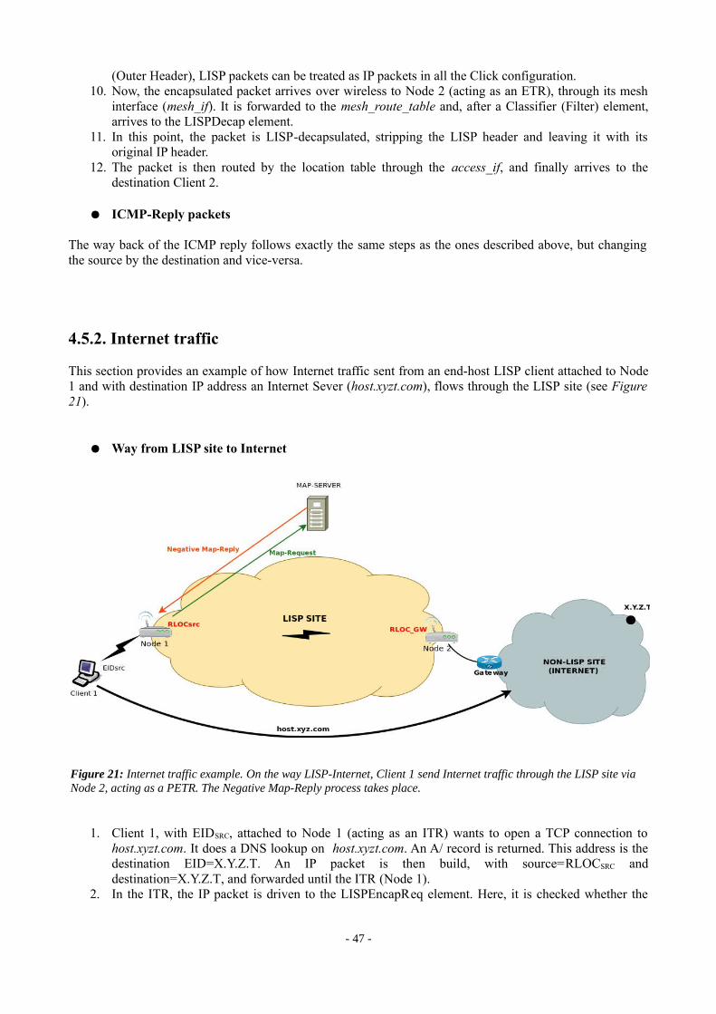
(Outer Header), LISP packets can be treated as IP packets in all the Click configuration.10. Now, the encapsulated packet arrives over wireless to Node 2 (acting as an ETR), through its mesh
interface (mesh_if). It is forwarded to the mesh_route_table and, after a Classifier (Filter) element, arrives to the LISPDecap element.
11. In this point, the packet is LISP-decapsulated, stripping the LISP header and leaving it with its original IP header.
12. The packet is then routed by the location table through the access_if, and finally arrives to the destination Client 2.
● ICMP-Reply packets
The way back of the ICMP reply follows exactly the same steps as the ones described above, but changing the source by the destination and vice-versa.
4.5.2. Internet traffic
This section provides an example of how Internet traffic sent from an end-host LISP client attached to Node 1 and with destination IP address an Internet Sever (host.xyzt.com), flows through the LISP site (see Figure 21).
● Way from LISP site to Internet
1. Client 1, with EIDSRC, attached to Node 1 (acting as an ITR) wants to open a TCP connection to host.xyzt.com. It does a DNS lookup on host.xyzt.com. An A/ record is returned. This address is the destination EID=X.Y.Z.T. An IP packet is then build, with source=RLOCSRC and destination=X.Y.Z.T, and forwarded until the ITR (Node 1).
2. In the ITR, the IP packet is driven to the LISPEncapReq element. Here, it is checked whether the
- 47 -
Figure 21: Internet traffic example. On the way LISP-Internet, Client 1 send Internet traffic through the LISP site via Node 2, acting as a PETR. The Negative Map-Reply process takes place.
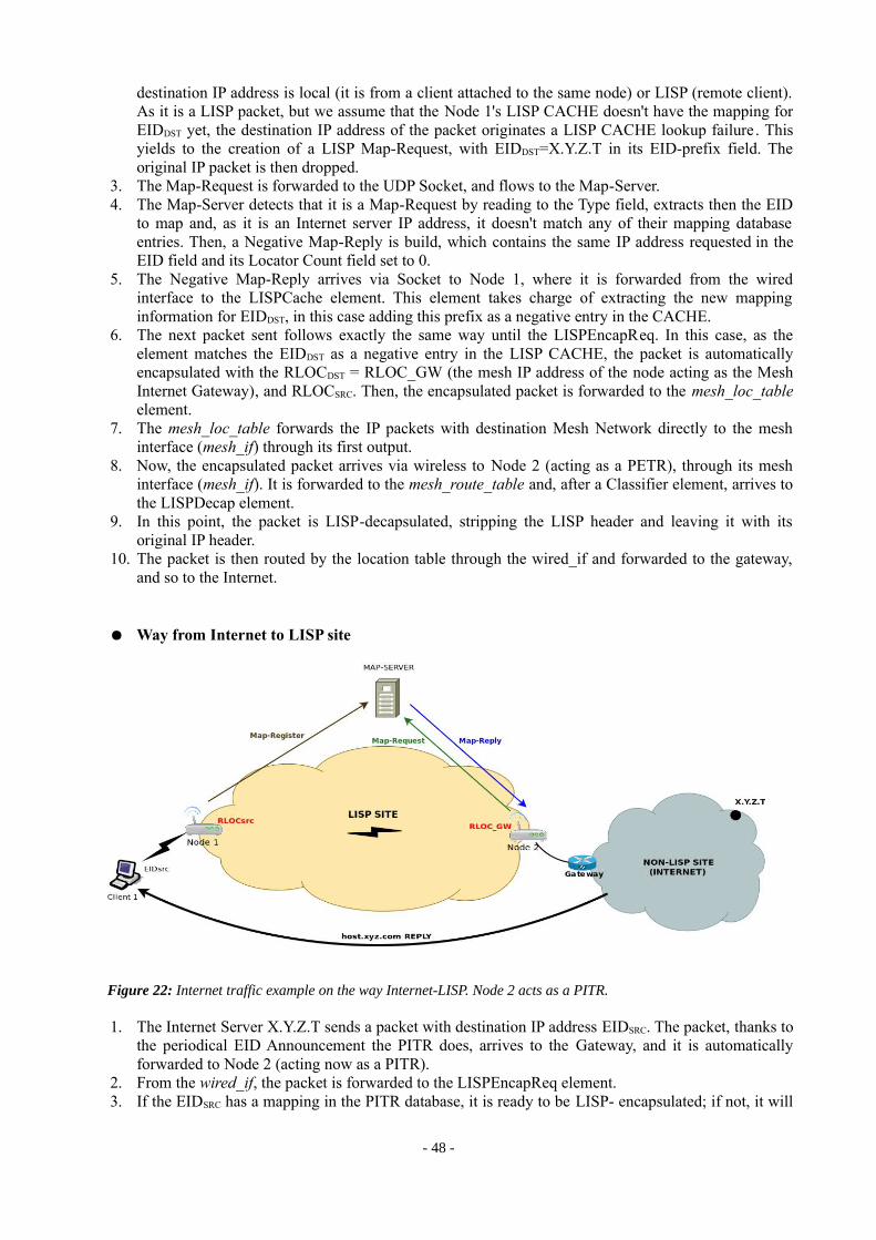
destination IP address is local (it is from a client attached to the same node) or LISP (remote client). As it is a LISP packet, but we assume that the Node 1's LISP CACHE doesn't have the mapping for EIDDST yet, the destination IP address of the packet originates a LISP CACHE lookup failure. This yields to the creation of a LISP Map-Request, with EIDDST=X.Y.Z.T in its EID-prefix field. The original IP packet is then dropped.
3. The Map-Request is forwarded to the UDP Socket, and flows to the Map-Server.4. The Map-Server detects that it is a Map-Request by reading to the Type field, extracts then the EID
to map and, as it is an Internet server IP address, it doesn't match any of their mapping database entries. Then, a Negative Map-Reply is build, which contains the same IP address requested in the EID field and its Locator Count field set to 0.
5. The Negative Map-Reply arrives via Socket to Node 1, where it is forwarded from the wired interface to the LISPCache element. This element takes charge of extracting the new mapping information for EIDDST, in this case adding this prefix as a negative entry in the CACHE.
6. The next packet sent follows exactly the same way until the LISPEncapReq. In this case, as the element matches the EIDDST as a negative entry in the LISP CACHE, the packet is automatically encapsulated with the RLOCDST = RLOC_GW (the mesh IP address of the node acting as the Mesh Internet Gateway), and RLOCSRC. Then, the encapsulated packet is forwarded to the mesh_loc_table element.
7. The mesh_loc_table forwards the IP packets with destination Mesh Network directly to the mesh interface (mesh_if) through its first output.
8. Now, the encapsulated packet arrives via wireless to Node 2 (acting as a PETR), through its mesh interface (mesh_if). It is forwarded to the mesh_route_table and, after a Classifier element, arrives to the LISPDecap element.
9. In this point, the packet is LISP-decapsulated, stripping the LISP header and leaving it with its original IP header.
10. The packet is then routed by the location table through the wired_if and forwarded to the gateway, and so to the Internet.
● Way from Internet to LISP site
1. The Internet Server X.Y.Z.T sends a packet with destination IP address EIDSRC. The packet, thanks to the periodical EID Announcement the PITR does, arrives to the Gateway, and it is automatically forwarded to Node 2 (acting now as a PITR).
2. From the wired_if, the packet is forwarded to the LISPEncapReq element. 3. If the EIDSRC has a mapping in the PITR database, it is ready to be LISP- encapsulated; if not, it will
- 48 -
Figure 22: Internet traffic example on the way Internet-LISP. Node 2 acts as a PITR.
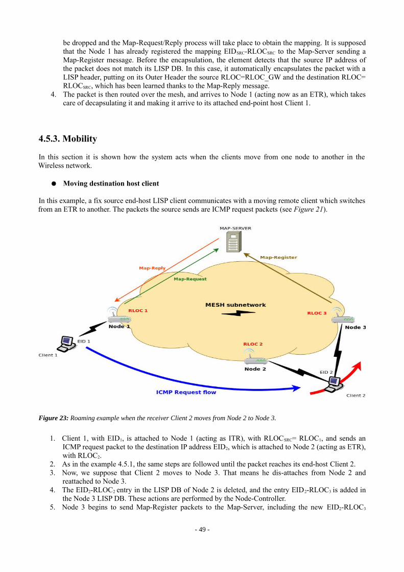
be dropped and the Map-Request/Reply process will take place to obtain the mapping. It is supposed that the Node 1 has already registered the mapping EIDSRC-RLOCSRC to the Map-Server sending a Map-Register message. Before the encapsulation, the element detects that the source IP address of the packet does not match its LISP DB. In this case, it automatically encapsulates the packet with a LISP header, putting on its Outer Header the source RLOC=RLOC_GW and the destination RLOC= RLOCSRC, which has been learned thanks to the Map-Reply message.
4. The packet is then routed over the mesh, and arrives to Node 1 (acting now as an ETR), which takes care of decapsulating it and making it arrive to its attached end-point host Client 1.
4.5.3. Mobility
In this section it is shown how the system acts when the clients move from one node to another in the Wireless network.
● Moving destination host client
In this example, a fix source end-host LISP client communicates with a moving remote client which switches from an ETR to another. The packets the source sends are ICMP request packets (see Figure 21).
1. Client 1, with EID1, is attached to Node 1 (acting as ITR), with RLOCSRC= RLOC1, and sends an ICMP request packet to the destination IP address EID2, which is attached to Node 2 (acting as ETR), with RLOC2.
2. As in the example 4.5.1, the same steps are followed until the packet reaches its end-host Client 2.3. Now, we suppose that Client 2 moves to Node 3. That means he dis-attaches from Node 2 and
reattached to Node 3. 4. The EID2-RLOC2 entry in the LISP DB of Node 2 is deleted, and the entry EID2-RLOC3 is added in
the Node 3 LISP DB. These actions are performed by the Node-Controller.5. Node 3 begins to send Map-Register packets to the Map-Server, including the new EID2-RLOC3
- 49 -
Figure 23: Roaming example when the receiver Client 2 moves from Node 2 to Node 3.

mapping into them. In the Map-Server's database, the EID2-RLOC2 mapping entry is replaced by the new EID2-RLOC3 mapping.
6. In the next ICMP-Request packet, the ITR (Node 1) will map the EID2 with the RLOC2,, and encapsulate the packet via Node 2, which will never reach its destination because client 2 has moved. This and the next packets will be lost, until the TIMEOUT of the LISP CACHE for the EID2 entry expires on Node 1.
7. At this moment, when Client 1 sends a ICMP packet to Client 2 again, the ITR will run out with a CACHE “miss”, because the entry would have been deleted. At this point, the Map Resolver procedure (Map Request/Map Reply) will take place to update the LISP CACHE entry matching the EID2.
8. The next packet will finally be LISP-encapsulated with the RLOC3 in its outer header destination IP address, reaching then Node 3, being then LISP-decapsulated and forwarded finally to Client 2.
● Moving source host client
What follows is an example of a source moving end-host LISP client sending ICMP packets to a fix end-host LISP client. The source client is moving from Node 1 to Node 3 (see Figure 22). In this example it is involved the Node Controller process of Nodes 1 and 3, which will update their LISP DB (see Section 4.4.1 for more information).
1. Client 1, with IP address EID1, is attached to Node 1 (acting as ITR), with RLOC1, and sends an ICMP request packet to the destination IP address EID2, corresponding of a client attached to Node 2 (acting as ETR), with RLOC2. In the local LISP DB of Node 1 features the entry of the pair EID1-RLOC1, which has been written by the Node-Controller.
2. In the meantime, Node 1 sends LISP Map Register control packets to the Map-Server, in order to inform the mapping of its attached Client 1.
3. The flow of the ICMP packets (requests and replies) follow the same steps as in the example 4.5.1. 4. Now, Client 1 moves to Node 3, what means that dis-attaches from Node 1 and re-attaches to Node
3. First, the Node-Controller process running in Node 1 detects that Client 1 has dis-attached from
- 50 -
Figure 24: Roaming example when the sender Client 1 moves from Node 1 to Node 3.

Node 1, and removes the instance of EID1-RLOC1 in the LISP DB. The LISP Map Register packets, sent periodically, won't contain any more this record. Second, the Node-Controller acting in Node 3 will detect a new client attachment, and then will update the Node 3 LISP DB with the new entry EID1-RLOC3. The next Map-Register packets leaving Node 3 will inform the Map-Server about the new mapping of Client 1 EID1-RLOC3.
5. In the interval the node disconnects from Node 1 and connects to Node 2, all packets will be lost.6. The next ICMP packets will be LISP-encapsulated with the new source RLOC, RLOC3.
- 51 -

5. EVALUATION
In this chapter, LISP is tested in the Indoor BOWL testbed. Two kind of traffic are injected into the LISP site in order to measure the main network evaluation parameters: TCP and UDP Local traffic (between two clients attached to the LISP site). What's more, the LISP site is also tested with Internet traffic.
Two different scenarios are considered: the Static case, where fix clients are associated to the nodes and don't move, and the Mobility case, where clients roam from one node to another.
In addition, the same kind of measurements are made for both the LISP configuration and the basic IP -in-IP BOWL configuration, in order to compare the results and achieve conclusions on both protocols.
It is important to take in account that this experiment is done over wireless. That means that a lot of external factors can modify the final results provided by the different measurement tools. We have to consider, firstly, the fact that the measurements are taken in the 16 th floor of the T-Labs building, where there is a lot of people working in an “office environment”; this can cause a lot of interferences and bad wireless connectivity in our setup. Secondly, the wireless configuration of all the links can lead to a variation on the results. For instance, regarding throughput, different values of the wireless rate parameter can modify the real measured throughput.
In order to solve these issues, the experiments have been done in a precise out-of-work time and taking the wireless channels less used. Basically, the physical scenario that has been taken for the measurements is the represented in the following map:
The tools used to make all the measurements are described in Section 3.1.3.
- 52 -
Figure 25: Scenario used for the measurements. 3 nodes of the Indoor BOWL network are taken to deploy the static, the mobility and the Internet traffic scenarios.

5.1. Local Traffic
For Local traffic, a experiment has been done for both the static and the mobility scenarios.
5.1.1. Static Scenario
Figure 20 shown in Section 4.5.1 represents the scenario it has been used to take the static measurements. It has been considered two kind of traffic: TCP and UDP. For each one, the same measurements have been taken for both the LISP and the basic IPIP BOWL configurations, in order to compare both proposals.
Also, regarding the wireless rate set up on every link, every experiment has been done twice: one with the wireless rate set to automatic, and one with the wireless rate fixed to the minimum rate available. The reason of this consideration is that fixing a Wireless Link Rate avoids variability on the results regarding this aspect, because when setting it to Automatic the access points switch their wireless link rate all the time depending on the wireless connectivity.
5.1.1.1. TCP traffic
The tool for injecting TCP traffic to the Indoor BOWL testbed is iperf, described in Section 3.1.3. The main goal of this experiment is to measure the TCP Throughput between two end-point clients attached to different Access Points in the LISP site, sending from one to another the significant amount of traffic of 10 MBytes.
Wireless Link Rate set to Automatic
The difference between the Average TCP Throughput in the IPIP and LISP configurations is 0.54 Mbits/sec. Despite the fact that this measurements have been taken in night time in order to avoid as much as possible the factors that might reduce the wireless bandwidth, we have to take in account that the wireless measurements might not describe the reality as in a wired connection. However, in this case the difference of Average TCP Throughput obtained is quite reasonable, considering that the LISP header is bigger than the IPIP one:
- 53 -
Figure 26: Average TCP Throughput in 10 measurements. 10 MBytes sent. Wireless Link Rate set to Auto.
IPIP LISP
0
1
2
3
4
5
6
7
6,295,75
TC
P T
hro
ug
hp
ut
[Mb
its
/se
c]
Figure 27: Average Tansfer Time in 10 measurements. 10 Mbytes sent.Link Rate set to Auto.
IPIP LISP
0
2
4
6
8
10
12
14
16
13,3814,63
10
MB
Tra
ns
fer
Tim
e [
se
c]

Since the MTU is the same for both protocols, LISP-encapsulated packets contain less data than IPIP packets, and considering the Average Throughput is calculated with Bytes of Data, it is coherent that the LISP Throughput is lower than the IPIP one.
Wireless Link Rate limited to 1 Mbps
Configuring a Wireless Link Rate limited to 1 Mbps, the lower available for Wireless links in the 2,4 GHz band, it is supposed to avoid the variability of the TCP Throughput measured due to changes in the wireless link and at the same time ensure connectivity.
As we can see in Figure 29, regarding the fact that the Maximum Throughput available is 1 Mbit/sec, it is obtained more or less half of it, what means that the wireless link connectivity utilization parameter is about 50%.
In this case, the difference of TCP Throughput obtained at the Receiver side is 107.7 Kbits/sec. Considering the proportion in Figure 29, this difference should not be such big, but the measurements have been done in different time moments and a lot of external factors can have modified them. In addition, the Standard Deviation in the LISP case is bigger than in the IPIP case, what means there is more variability in the measurements made.
- 54 -
Figure 28: IPIP and LISP Headers. Difference of 16 Bytes between them.
Figure 29: Average TCP Throughput in 10 measurements. 2 Mbytes sent.Link Rate set to 1 Mbit/sec.
IPIP LISP
0
100
200
300
400
500
600
700
800
900
1000
646,3538,6
TC
P T
hro
ug
hp
ut
[Mb
its
/se
c]
Figure 30: Average Tansfer Time in 10 measurements. 2 Mbytes sent.Link Rate set to 1 Mbit/sec.
IPIP LISP
0
5
10
15
20
25
30
35
40
26,3632,13
10
MB
Tra
ns
fer
Tim
e [
se
c]

5.1.1.2. UDP traffic
The UDP traffic is also injected using iperf. Using the Average TCP throughput from the previous experiment as UDP Bandwidth injected, it is measured the Maximum Bandwidth reached between two end-point clients, as well as the Packet Loss percentage. As well, the same experiment is repeated for an Automatic Wireless Link Rate and for one set to 1 Mbps.
Wireless Link Rate set to Automatic
In the case of UDP traffic the differences in the header of both protocols causes a difference in the UDP Bandwidth reached at reception, which is in Average 0,43 Mbits/sec.
As shown in Figure 32, the Percentage of Packet Loss is similar in both protocols, with a little increase in the LISP case corresponding to the difference in the Bandwidth measured. In addition, regarding to the methodology for encapsulating in both protocols, under the same conditions the LISP Packet Loss will be always higher due to the packets that are dropped when soliciting a Mapping for an EID (see Section 2.4.2.1 for further information).
As well, the measurements taken in the LISP case have more variability, what can be caused by external factors on the wireless link.
Wireless Link Rate set to 1 Mbps
In this case, the UDP Flow is sent at a rate of 1 Mbit/sec, the maximum theoretical Bandwidth due to the link limitation capacity. The UDP magnitudes obtained when limiting the Link Rate to the minimum available (1 Mbit/sec) are the following:
- 55 -
Figure 31: Average UDP Bandwidth reached in Reception in 10 measurements. Sender Bandwidth 6.2 Mbit/sec for IPIP, 5.7 Mbit/sec for LISP. Link Rate set to Auto.
IPIP LISP
0
1
2
3
4
5
6
7
5,615,18
Ba
nd
wid
th R
ec
eiv
ed
[M
bit
s/s
ec
]
Figure 32: Average UDP Packet Loss in 10 measurements. Sender Bandwidth 6.2 Mbit/sec for IPIP, 5.7 Mbit/sec for LISP. Link Rate set to Auto.
IPIP LISP
0
5
10
15
20
25
30
35
40
45
50
9,53 9,59
Pa
ck
et
Lo
ss
[%
]

In this case, the UDP Bandwidth reached at reception is higher for LISP than for IPIP. Considering that the differences between both headers is only 16 Bytes and that the MTU is 1500 Bytes, both protocols should have similar bandwidths because the difference on their headers is so little. So, we can justify the inconsiderable increase of Bandwidth (30 Kbits/sec) in the LISP case in respect to the IPIP case by the influence of external factors in the wireless link.
5.1.1.3. TCP and UDP Bandwidths
In this section, using the same results as the ones obtained in Section 5.1.1.1 and 5.1.1.2 another point of comparison has been taken, regarding the Bandwidth reached at reception for TCP and UDP traffic.
For the Wireless Link Rate set to Automatic, the following Figures show the difference between both kind of traffic in the IPIP and LISP cases.
As shown in Figures 35 and Figure 36, the difference between TCP and UDP Bandwidths reached at reception is 0.69 Mbits/sec for IPIP and 0.57 Mbits/sec for LISP. For both protocols a similar behavior is happening, but in the LISP case the difference is lower because of its bigger header.
To justify the decrease of Bandwidth in the UDP case it has to be considered the fact that the TCP Average Bandwidth obtained has been used as UDP Bandwidth sent. Thus, the maximum UDP Bandwidth obtainable at reception is limited by this value. Injecting UDP traffic at the TCP rate obtained in a wireless network, it can happen that packets get lost on their path due to wireless issues, decreasing then the bandwidth since packets continue being sent at the same rate without acknowledging them, and finally obtaining the real bandwidth of the connection.
- 56 -
Figure 33: Average UDP Bandwidth reached in Reception in 10 measurements. Sender Bandwidth 1Mbit/sec in both IPIP and LISP. Link Rate set to 1 Mbps.
IPIP LISP
0
100
200
300
400
500
600
700
800
900
1000
660,1 690,1
Ba
nd
wid
th R
ec
eiv
ed
[M
bit
s/s
ec
]
Figure 34: Average UDP Packet Loss in 10 measurements. Sender Bandwidth 1 Mbit/sec in both IPIP and LISP. Link Rate set to 1 Mbps.
IPIP LISP
0
5
10
15
20
25
30
35
40
45
50
29,5 28,4
Pa
ck
et
Lo
ss
[%
]
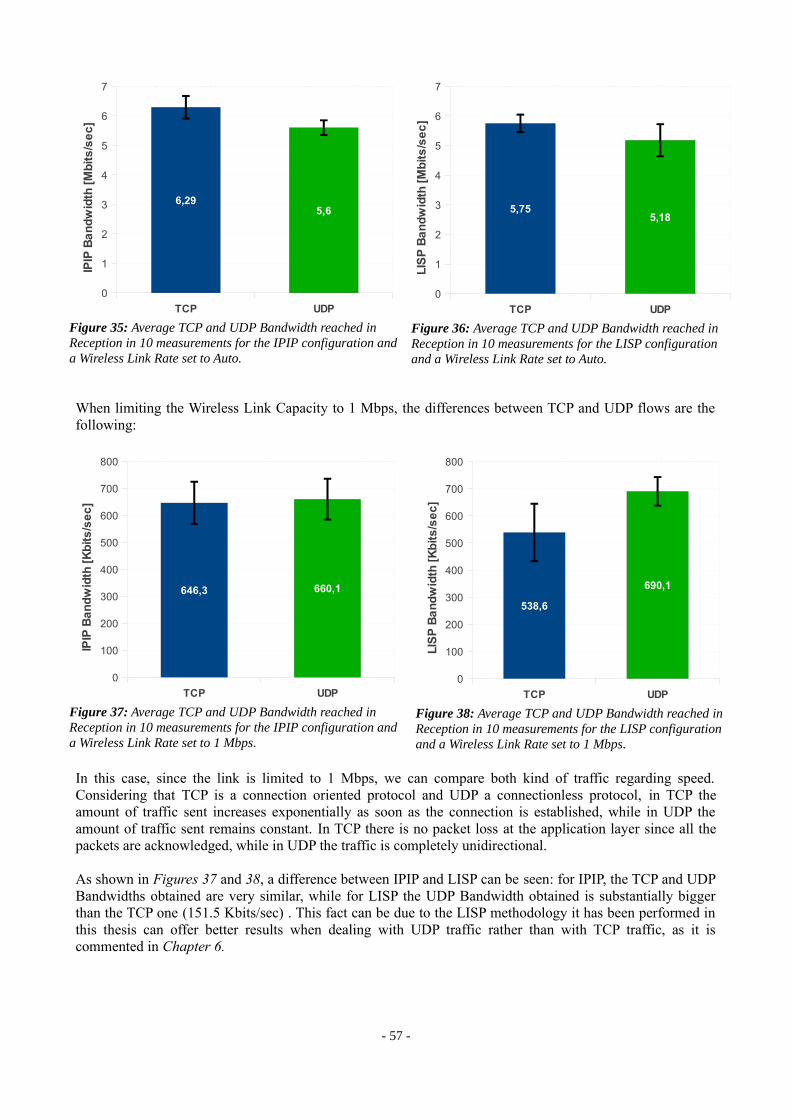
When limiting the Wireless Link Capacity to 1 Mbps, the differences between TCP and UDP flows are the following:
In this case, since the link is limited to 1 Mbps, we can compare both kind of traffic regarding speed. Considering that TCP is a connection oriented protocol and UDP a connectionless protocol, in TCP the amount of traffic sent increases exponentially as soon as the connection is established, while in UDP the amount of traffic sent remains constant. In TCP there is no packet loss at the application layer since all the packets are acknowledged, while in UDP the traffic is completely unidirectional.
As shown in Figures 37 and 38, a difference between IPIP and LISP can be seen: for IPIP, the TCP and UDP Bandwidths obtained are very similar, while for LISP the UDP Bandwidth obtained is substantially bigger than the TCP one (151.5 Kbits/sec) . This fact can be due to the LISP methodology it has been performed in this thesis can offer better results when dealing with UDP traffic rather than with TCP traffic, as it is commented in Chapter 6.
- 57 -
Figure 35: Average TCP and UDP Bandwidth reached in Reception in 10 measurements for the IPIP configuration and a Wireless Link Rate set to Auto.
TCP UDP
0
1
2
3
4
5
6
7
6,295,6
IPIP
Ba
nd
wid
t h [
Mb
its
/se
c]
Figure 36: Average TCP and UDP Bandwidth reached in Reception in 10 measurements for the LISP configuration and a Wireless Link Rate set to Auto.
TCP UDP
0
1
2
3
4
5
6
7
5,755,18
LIS
P B
an
dw
idth
[M
bit
s/s
ec
]
Figure 37: Average TCP and UDP Bandwidth reached in Reception in 10 measurements for the IPIP configuration and a Wireless Link Rate set to 1 Mbps.
TCP UDP
0
100
200
300
400
500
600
700
800
646,3 660,1
IPIP
Ba
nd
wid
t h [
Kb
its
/se
c]
Figure 38: Average TCP and UDP Bandwidth reached in Reception in 10 measurements for the LISP configuration and a Wireless Link Rate set to 1 Mbps.
TCP UDP
0
100
200
300
400
500
600
700
800
538,6
690,1
LIS
P B
an
dw
idth
[K
bit
s/s
ec
]

5.1.2. Mobility Scenario
One of the goals of this project is to research in the Wireless Mobility domain. Hence, in two Mobility scenarios have been performed and tested as well with TCP and UDP traffic: in the first, the receiver of the connection roams an access point to another, and in the second it's the sender who roams.
The mechanism to make the end-point client to roam from Access Point 2 to Access Point 3 is to disable the access interface from AP2, forcing it to attach to AP3.
As well, two different kind of traffic are injected into the Indoor testbed (TCP and UDP). What changes from the static experiment is that in this case, in the middle of the time when flowing the traffic between both end-point clients, one of the clients roams from an access point to another: it changes the access point where he is attached. This fact implies a variation in the different parameters measured due to the disconnection time of the Roaming process.
In this case, the measurements for both IPIP and LISP configurations are treated separately, due to the differences between these protocols regarding mobility.
Also, the following measurements have been taken configuring the Wireless Link Rate as Automatic.
5.1.2.1. Receiver Roaming
In this experiment, the same experiments of the Static scenario are repeated, but in this case using the scenario defined in the figure below:
5.1.2.1.1. TCP traffic
TCP traffic is also injected between both clients for a period of 60 seconds. In the middle time of the process, the destination client roams to a new Access Point. The main goal of this experiment is to analyze the time of disconnection and the consequent TCP reaction.
- 58 -
Figure 39: Roaming scenario of the destination client.

• IPIP configuration
In the IPIP configuration, when the destination client roams in the middle of a TCP connection, the client suffers a disconnection time in which it disconnects from his current Access Point and attaches to the new one. At the moment of attaching to the new one, the Node Manager updates the Click mesh_loc_table8 of all the nodes by means of a Callback9 that is performed at the moment the client attaches to the new node. The disconnection time the receiver suffers is the sum of the wireless roaming10 time and the time needed to update the mesh_loc_table with the new route.
In the meantime, the sender stops receiving acknowledgements due to the receiver's disconnection and then the TCP congestion control mechanism takes place, in which retransmission packets are send until the receiver acknowledges them. The TCP congestion control process specifies a Retransmission Timeout proportional to the Round Trip delay Time (RTT)11 measured at the Connection Establishment. Every time a retransmission is sent, the time between retransmissions is doubled. Note that this time is very significant for the determination of the TCP Flow disconnection time when roaming, as it will be shown for the LISP implementation.
As we can see in Figure 40, the pixels of Throughput captured at the instances 40s and 45s confirm the TCP retransmissions of the sender, which are not received at reception shown in Figure 41. The two first retransmissions are lost due to wireless issues, and the third one finally is acknowledged at the instance t=53s, when the connection is re-established. In the case of Figures 40 and 41, the TCP Flow disconnection time is approx. 16 seconds.
In the Figure 42 below, it is represented the Disconnection Time measured in 10 repetitions of the same experiment, with an average value of 16.51seconds.
8 See Section 3.5.2. for more information.9 See Section 3.4 for more information.10 This is the process that takes place when a client roams form an access point to another. First, the client sends an Assoc request message to the
new access point requesting the association. If it is possible, the access point responds with an Assoc reply message, allowing the connection. When the 802.1x Authentication protocol is enabled, to this process it is added the EAP mechanism in order to authenticate the client.
11 RTT: The length of time it takes for a packet to be sent plus the length of time it takes for an acknowledgment of that packet to be received.
- 59 -
Figure 40: IPIP TCP Throughput on the Sender side when the destination client roams.
Figure 41: IPIP TCP Throughput on the Receiver side when the destination client roams.
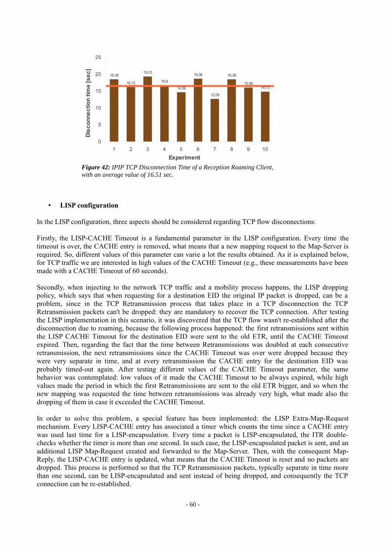
• LISP configuration
In the LISP configuration, three aspects should be considered regarding TCP flow disconnections:
Firstly, the LISP-CACHE Timeout is a fundamental parameter in the LISP configuration. Every time the timeout is over, the CACHE entry is removed, what means that a new mapping request to the Map-Server is required. So, different values of this parameter can varie a lot the results obtained. As it is explained below, for TCP traffic we are interested in high values of the CACHE Timeout (e.g., these measurements have been made with a CACHE Timeout of 60 seconds).
Secondly, when injecting to the network TCP traffic and a mobility process happens, the LISP dropping policy, which says that when requesting for a destination EID the original IP packet is dropped, can be a problem, since in the TCP Retransmission process that takes place in a TCP disconnection the TCP Retransmission packets can't be dropped: they are mandatory to recover the TCP connection. After testing the LISP implementation in this scenario, it was discovered that the TCP flow wasn't re-established after the disconnection due to roaming, because the following process happened: the first retransmissions sent within the LISP CACHE Timeout for the destination EID were sent to the old ETR, until the CACHE Timeout expired. Then, regarding the fact that the time between Retransmissions was doubled at each consecutive retransmission, the next retransmissions since the CACHE Timeout was over were dropped because they were very separate in time, and at every retransmission the CACHE entry for the destination EID was probably timed-out again. After testing different values of the CACHE Timeout parameter, the same behavior was contemplated: low values of it made the CACHE Timeout to be always expired, while high values made the period in which the first Retransmissions are sent to the old ETR bigger, and so when the new mapping was requested the time between retransmissions was already very high, what made also the dropping of them in case it exceeded the CACHE Timeout.
In order to solve this problem, a special feature has been implemented: the LISP Extra-Map-Request mechanism. Every LISP-CACHE entry has associated a timer which counts the time since a CACHE entry was used last time for a LISP-encapsulation. Every time a packet is LISP-encapsulated, the ITR double-checks whether the timer is more than one second. In such case, the LISP-encapsulated packet is sent, and an additional LISP Map-Request created and forwarded to the Map-Server. Then, with the consequent Map-Reply, the LISP-CACHE entry is updated, what means that the CACHE Timeout is reset and no packets are dropped. This process is performed so that the TCP Retransmission packets, typically separate in time more than one second, can be LISP-encapsulated and sent instead of being dropped, and consequently the TCP connection can be re-established.
- 60 -
Figure 42: IPIP TCP Disconnection Time of a Reception Roaming Client, with an average value of 16.51 sec.
1 2 3 4 5 6 7 8 9 10
0
5
10
15
20
25
18,38
16,12
19,23
16,6
14,56
18,56
12,59
18,38
15,9614,72
Experiment
Dis
co
nn
ec
tio
n t
ime
[s
ec
]

Thirdly, another fundamental LISP parameter is the Registration Time. Every Registration Time, the ETRs publish their associated clients by sending LISP Map-Register packets to the Map-Server. When a client roams, the Map-Server won't have the new mapping for his EID until the new Access Point sends the Map-Register containing this information.
For the TCP measurements in the roaming scenario, it has been chosen a LISP-CACHE Timeout of 60 seconds, and a registration period of 5 seconds.
When the destination client roams in the middle of a TCP connection, the receiver suffers a disconnection time equal to the sum of the wireless roaming for attaching to the new access point, the time Node-Manager updates the new access point LISP-DB with the new EID (by means of a Callback), and the time the new access point needs to publish its new client attached to the Map-Server by means of a Map-Register packet. Note that this time is not fixed, it varies depending on the three parts added together.
In the meantime, the TCP Congestion Control takes place in the sender side. The sender begins sending TCP retransmission packets, each one separate a bigger period of time from the previous one. As shown in Figure 43, after the disconnection that takes place in Time=13s, the sender sends several retransmission packets, separate an interval of time growing up every time. Every time a retransmission is sent, the LISP Extra-Map-Request process takes place since every retransmission is sent in an interval of time higher than one second. Unless the LISP-CACHE entry for the destination EID times-out before the first retransmission, no retransmission packets are dropped; instead, the first ones are encapsulated via the old ETR, while extra Map-Requests are sent, until the ITR has the correct mapping for the destination EID on its CACHE.
At this point we shall define two different times calculated with the measurements taken in this section:
• The TCP one-way connectivity disconnection time: the time spent from the instant of disconnection due to roaming until the first TCP Retransmission packet arrives to the receiver. After this time, the one-way connectivity is re-established, since the ITR has the mapping for the destination EID up-to-date in its LISP CACHE (thanks to the LISP Mapping process).
• The TCP two-way connectivity disconnection time: the time spent from the instant of disconnection due to roaming until the TCP flow is re-established. After this time, both ITR and the new ETR have the corresponding mappings for the source EID and destination EID on their LISP CACHE, what means that both the TCP segments and their Acknowledgements can reach their destination successfully. Consequently, the two-way (or bidirectional) connectivity is recovered, and so does the TCP flow.
- 61 -
Figure 43: LISP TCP Throughput on the Sender side when the destination client roams.
Figure 44: LISP TCP Throughput on the Sender side when the destination client roams.
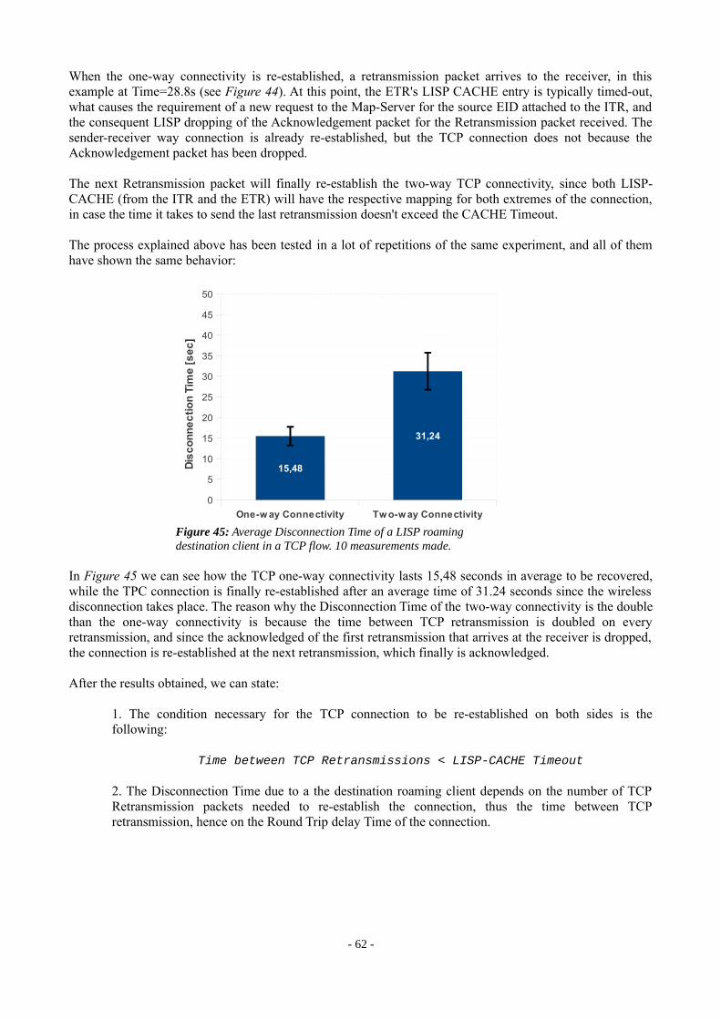
When the one-way connectivity is re-established, a retransmission packet arrives to the receiver, in this example at Time=28.8s (see Figure 44). At this point, the ETR's LISP CACHE entry is typically timed-out, what causes the requirement of a new request to the Map-Server for the source EID attached to the ITR, and the consequent LISP dropping of the Acknowledgement packet for the Retransmission packet received. The sender-receiver way connection is already re-established, but the TCP connection does not because the Acknowledgement packet has been dropped.
The next Retransmission packet will finally re-establish the two-way TCP connectivity, since both LISP-CACHE (from the ITR and the ETR) will have the respective mapping for both extremes of the connection, in case the time it takes to send the last retransmission doesn't exceed the CACHE Timeout.
The process explained above has been tested in a lot of repetitions of the same experiment, and all of them have shown the same behavior:
In Figure 45 we can see how the TCP one-way connectivity lasts 15,48 seconds in average to be recovered, while the TPC connection is finally re-established after an average time of 31.24 seconds since the wireless disconnection takes place. The reason why the Disconnection Time of the two-way connectivity is the double than the one-way connectivity is because the time between TCP retransmission is doubled on every retransmission, and since the acknowledged of the first retransmission that arrives at the receiver is dropped, the connection is re-established at the next retransmission, which finally is acknowledged.
After the results obtained, we can state:
1. The condition necessary for the TCP connection to be re-established on both sides is the following:
Time between TCP Retransmissions < LISP-CACHE Timeout
2. The Disconnection Time due to a the destination roaming client depends on the number of TCP Retransmission packets needed to re-establish the connection, thus the time between TCP retransmission, hence on the Round Trip delay Time of the connection.
- 62 -
Figure 45: Average Disconnection Time of a LISP roaming destination client in a TCP flow. 10 measurements made.
One-w ay Connectivity Tw o-w ay Connectivity
0
5
10
15
20
25
30
35
40
45
50
15,48
31,24
Dis
co
nn
ec
tio
n T
ime
[s
ec
]

5.1.2.1.2. UDP traffic
Since the goal of this experiment is to measure the disconnection time due to roaming, the UDP flow is injected to the network at a rate of 2 Mbits/sec, without considering the Average Throghput obtained in the TCP analog experiment. In this case, the destination client roams as well to a new Access Point.
• IPIP configuration
The following Figure represents the UDP Bandwidth received in the destination client when he roams from an Access Point to another.
In this case, since the UDP traffic is only one-way traffic, the disconnetion time suffered in the UDP flow, calculated as the time between the last and first packets received before and after the roaming disconnection respectively, is equal to the wireless roaming, plus the time the Node Manager takes to update the mesh_loc_table of the ITR that performs the IPIP tunneling – by means of the Callback process-, plus the transmission time a UDP packet takes from the source to the destination.
The same experiment has been repeated 10 times in order to obtain the Average Disconnection time at Reception, as shown in the figure below:
- 63 -
Figure 46: IPIP UDP Packet Flow in a reception roaming client sending with a BW=2 Mbits/sec. Disconnection Time of 9.15 sec.
Figure 47: IPIP UDP disconnection time in a Reception Roaming Client, sending with a BW=2MBit/sec. Average Value of 11.71 sec.
1 2 3 4 5 6 7 8 9 10
0
2
4
6
8
10
12
14
16
18
9,12 9,16
14,16
12,28
16,27
9,62
15,02
7,31
9,12
15,11
Experiment
Dis
co
nn
ec
tio
n t
ime
[s
ec
]
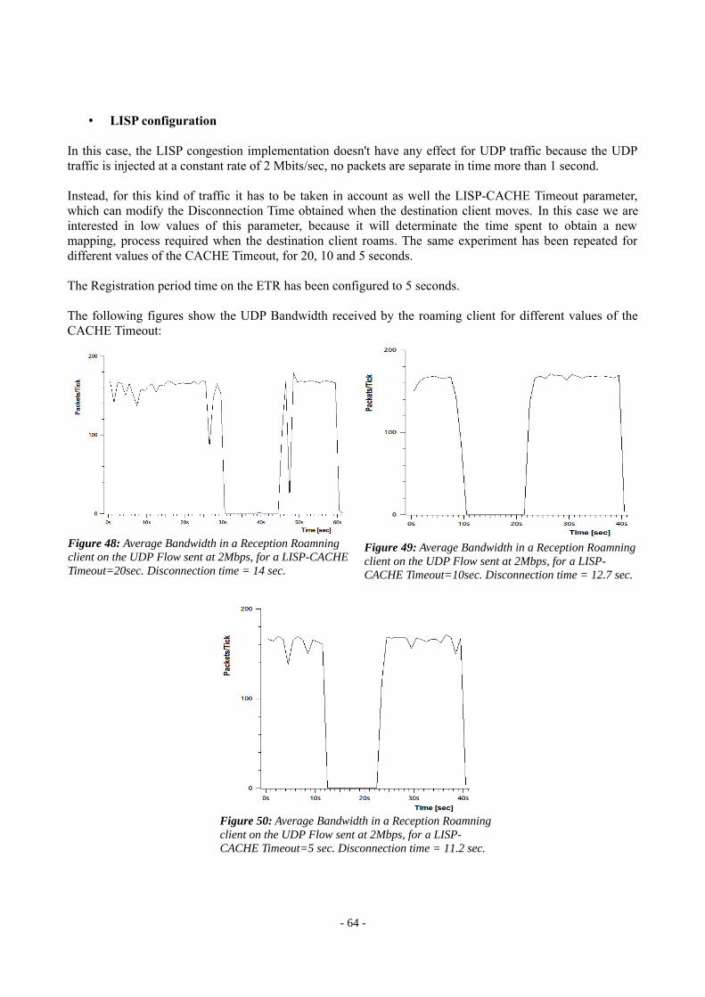
• LISP configuration
In this case, the LISP congestion implementation doesn't have any effect for UDP traffic because the UDP traffic is injected at a constant rate of 2 Mbits/sec, no packets are separate in time more than 1 second.
Instead, for this kind of traffic it has to be taken in account as well the LISP-CACHE Timeout parameter, which can modify the Disconnection Time obtained when the destination client moves. In this case we are interested in low values of this parameter, because it will determinate the time spent to obtain a new mapping, process required when the destination client roams. The same experiment has been repeated for different values of the CACHE Timeout, for 20, 10 and 5 seconds.
The Registration period time on the ETR has been configured to 5 seconds.
The following figures show the UDP Bandwidth received by the roaming client for different values of the CACHE Timeout:
N
- 64 -
Figure 48: Average Bandwidth in a Reception Roamning client on the UDP Flow sent at 2Mbps, for a LISP-CACHE Timeout=20sec. Disconnection time = 14 sec.
Figure 49: Average Bandwidth in a Reception Roamning client on the UDP Flow sent at 2Mbps, for a LISP-CACHE Timeout=10sec. Disconnection time = 12.7 sec.
Figure 50: Average Bandwidth in a Reception Roamning client on the UDP Flow sent at 2Mbps, for a LISP-CACHE Timeout=5 sec. Disconnection time = 11.2 sec.
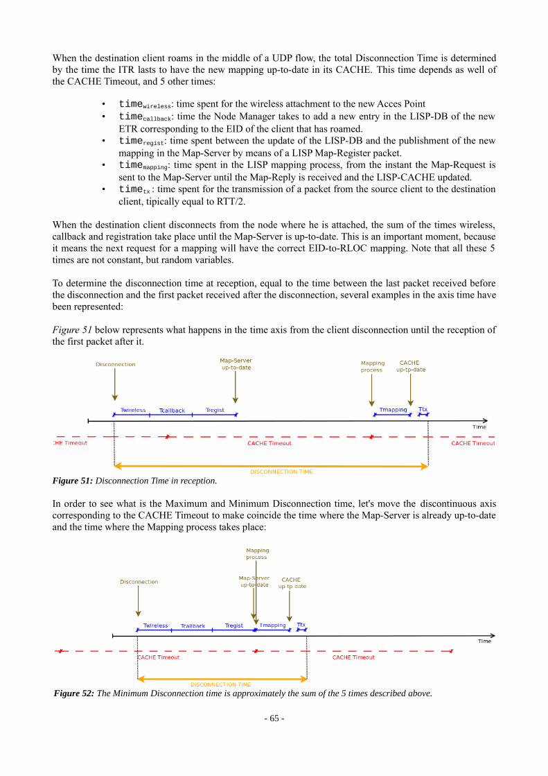
When the destination client roams in the middle of a UDP flow, the total Disconnection Time is determined by the time the ITR lasts to have the new mapping up-to-date in its CACHE. This time depends as well of the CACHE Timeout, and 5 other times:
• timewireless: time spent for the wireless attachment to the new Acces Point• timecallback: time the Node Manager takes to add a new entry in the LISP-DB of the new
ETR corresponding to the EID of the client that has roamed.• timeregist: time spent between the update of the LISP-DB and the publishment of the new
mapping in the Map-Server by means of a LISP Map-Register packet.• timemapping: time spent in the LISP mapping process, from the instant the Map-Request is
sent to the Map-Server until the Map-Reply is received and the LISP-CACHE updated.• timetx : time spent for the transmission of a packet from the source client to the destination
client, tipically equal to RTT/2.
When the destination client disconnects from the node where he is attached, the sum of the times wireless, callback and registration take place until the Map-Server is up-to-date. This is an important moment, because it means the next request for a mapping will have the correct EID-to-RLOC mapping. Note that all these 5 times are not constant, but random variables.
To determine the disconnection time at reception, equal to the time between the last packet received before the disconnection and the first packet received after the disconnection, several examples in the axis time have been represented:
Figure 51 below represents what happens in the time axis from the client disconnection until the reception of the first packet after it.
In order to see what is the Maximum and Minimum Disconnection time, let's move the discontinuous axis corresponding to the CACHE Timeout to make coincide the time where the Map-Server is already up-to-date and the time where the Mapping process takes place:
- 65 -
Figure 51: Disconnection Time in reception.
Figure 52: The Minimum Disconnection time is approximately the sum of the 5 times described above.

As shown in Figure 52, the minimum disconnection time is equal to the sum of the 5 times described above. As well, we can represent the maximum disconnection time by moving the red axis a little bit to the left, forcing that the CACHE Timeout occurs just an instant before the Map-Server is up-to-date:
So, the maximum disconnection time is approximately the sum of the 5 times described above plus the LISP-CACHE Timeout.
The following Figure represents the Average Disconnection Time at reception measured in the repetition of 10 experiments, with CACHE Timeout values of 20 seconds, 10 seconds, and 5 seconds:
As shown, for CACHE-Timeout=20s the Average Timeout is lower than the CACHE-Timeout, but for the other two cases the Disconnection time is bigger than the CACHE-Timeout. This fact happens because there is a “fixed” delay represented by the minimum CACHE-Timeout described above.
- 66 -
Figure 53: The Maximum Disconnection time is approximately the sum of the 5 times described above plus an extra CACHE Timeout.
Figure 54: Average Disconnection Time at Reception in the UDP flow sent at 2Mbps, in 10 measurements and for different values of the LISP-CACHE Timeout
Cache=20s Cache=10s Cache=5s
0
5
10
15
20
25
30
16,45
11,989,67D
isc
on
ne
cti
on
Tim
e [
se
c]

5.1.2.2. Sender Roaming
In this case it's the sender who roams from an Access Point to another in the middle of the traffic flow, as shown in the figure below:
5.1.2.2.1. TCP Traffic
When the source client that is sending TCP traffic roams from an Access Point to another in the middle of the flow, the sender stops the transmission due to the wireless disconnection. After he reconnects to the new Access Point, the TCP Retransmission mechanism takes place. On this mechanism depends the magnitude that will be measured in this section: the Disconnection Time that suffers the connection.
• IPIP configuration
Figures 56 and 57 show the captures done on both sides of a TCP flow when the sender is forced to roam. When the sender roams, the time he spends until he begins sending retransmission packets depends on the wireless re-attachment. After he associates to the new node, the Node Manager updates the Click mesh_loc_table on both ITR and ETR with the source client's new route. Since the time spent for this
- 67 -
Figure 55: Roaming scenario of the sender client.
Figure 56: IPIP TCP Throughput on the Sender side when the source client roams.
Figure 57: IPIP TCP Throughput on the Sender side when the source client roams.

process is very low, it is probable that the Acknowledgement packet of the first retransmission packet is correctly routed to the new access point. If not, the disconnection time that suffers the TCP flow depends then on the number of retransmission packets needed to send until they are correctly acknowledged. As shown in Figure 56, in this measurement 3 retransmission packets are needed to recover the connection: one at Time=15.5s, the second at Time=19.2s and the last one at Time=26.8s. As we can see in the receiver side, none of the two first retransmissions are received. This fact can be caused by wireless issues in the connectivity that have made the packets to get lost. Note that the Node Manager update process is not needed to make the retransmission packets arrive to the destination client after the disconnection because he didn't change his route, but it does to make the acknowledgement packets arrive back to the sender.
This measurement has been repeated several times in order to calculate the average disconnection time:
As shown in Figure 58 above, the disconnection time measured on each of the 10 measurements varies a lot, having a standard desviation of 9.7 seconds. We can divide the disconnection times obtained in the 10 measurements in 4 groups: the first, the experiments that have a disconnection time of about 4 seconds (Experiments 3 and 9); the second, the ones that have a disconnection time of about 8 seconds (Experiment 6); the third one with a value of approximately 16 seconds (Experiment 2, 4, 5, 7 and 10); and finally the last with a value of about 30 seconds (Experiments 1 and 8).
The reason why there is such difference in the results and from one group to the next one the values are doubled is because of the retransmission process. The time between retransmissions is doubled at each new retransmission needed, and that makes the disconnection time depend on this fact. For instance, the group of values of approx. 4 seconds have needed just one retransmission to re-establish the connection, while the group of values of about 30 seconds have needed 4 retransmissions. In the example of Figures 56 and 57, 3 retransmissions have been needed to obtain a disconnection time of 14.69 seconds.
• LISP configuration
When the sender of a TCP flow roams from an Access Point to another, a similar process than in the roaming receiver case happens. As in the receiver case, the LISP CACHE-Timeout parameter must be high so that it can cover the time between TCP Retransmission packets, and the LISP Extra-Map-Request congestion mechanism takes place.
For a LISP-CACHE Timeout of 60 seconds, the TCP Throughput captured in the sender and received sides is represented in the following figures:
- 68 -
Figure 58: IPIP Disconnection Time on a TCP flow when the when the source client roams, measured in 10 experiments. Average value of 15,48 sec.
1 2 3 4 5 6 7 8 9 10
0
5
10
15
20
25
30
35 32,04
14,88
3,81
17,1114,63
8,19
18,27
30,99
4,01
14,95
Experiment
Dis
co
nn
ec
tio
n t
ime
[s
ec
]

In the example shown in Figures 59 and 60 above, the time it takes to re-establish the TCP flow is about 16 seconds, while the time when the first retransmission packet arrives to the receiver is 8 seconds.
The same process as the described in Section 5.1.2.1.1 for the receiver roaming happens: the sender suffers a disconnection time due to wireless roaming, the Node Manager updates the LISP-DB with the roaming EID and the registration to the Map-Server takes place. After this, the sender begins sending retransmission packets. What happens here is usually the same process: the sender needs to transmit a minimum of 3 retransmission packets:
• The first retransmission packet is dropped by the LISP mechanism due to the fact that in the new access point the destination EID isn't registered yet in the CACHE, and the LISP mapping process takes place.
• The second retransmission packet arrives to the receiver, and the consequent Acknowledgement packet either is dropped because the receiver's CACHE is timed-out or it is sent back to the old Access Point. In the second case, since last time the CACHE EID entry was used more than 1 second ago, the Extra-Map-Request mechanism takes place, updating the LISP-CACHE entry with the new mapping and reseting the LISP-CACHE Timeout.
• The third retransmission packet is the one that finally recovers the connection, because it arrives successfully to the receiver and is successfully acknowledged as well.
As shown in Figure 59, the first retransmission is sent at Time=21s, the second at Time=24.5s (which arrives at the receiver), and the third one at Time=33s, when the TCP Flow is recovered.
The same experiment has been repeated several times and the Average Disconnection Time has been calculated, as shown in the figure below:
- 69 -
Figure 59: LISP TCP Throughput on the Sender side when the source client roams.
Figure 60: LISP TCP Throughput on the Receiver side when source client roams.

For each of the 10 measurements, the Unidirectional Flow Disconnection Time means the time from the disconnection due to roaming until the first retransmission packet arrives to the receiver. The Bidirectional Flow Disconnection Time is the time from the disconnection until the TCP flow is re-established.
As we can see in Figure 61 , some of the disconnection delays are about 60 seconds (Experiments 3,4,6,8 and 9), some about 30 seconds (Experiments 2 and 10), and some about 15 seconds (Experiments 1,5 and 7). This fact is caused by the possibility that more retransmission packets are needed in case they are lost due to wireless issues. That's why the higher disconnection times are the double of the lowers. The group of experiments with lower disconnection times correspond to the need of the minimum retransmission packets, equal to three.
In average, the disconnection time is the following:
As in the receiver roaming case for TCP traffic, the time between TCP Retransmission must not exceed the LISP-CACHE Timeout so that the TCP connection is re-established. As well, we can state that this time depends quite fully on the TCP congestion protocol, that means the time between TCP Retransmissions calculated from the RTT.
- 70 -
Figure 61: LISP Disconnection time on the Receiver side of a TCP connection, when the source client roams, for both Unidirectional and Bidirectional Connection.
Figure 62: LISP Average TCP Disconnection time on the Receiver side when the source client roams, for both One-way and Two-way connectivities.
1 2 3 4 5 6 7 8 9 10
0
10
20
30
40
50
60
70
80
8,05
15,88
31,5235,58
8,95
31,04
8,68
35,8832,04
16,4516,38
32,03
63,28
71,56
18,19
62,33
17,65
69,4664,35
33,14
One-way ConnectivityTwo-way Connectivity
Experiment
Dis
co
nn
ec
tio
n t
ime
[s
ec
]
One-w ay Connectivity Tw o-w ay Connectivity
0
10
20
30
40
50
60
15,48
31,24
Dis
co
nn
ec
tio
n T
ime
[s
ec
]

5.1.2.2.2. UDP Traffic
• IPIP configuration
In the IPIP set-up, it has been injected UDP traffic to the network at a BW=2Mbits/sec for a period of 40 seconds, and in the middle of the time the sender is forced to roam.
In this case, the Disconnection Time measured at reception is equal to the sum of the wireless roaming delay, the time the Node Manager takes to update the Click mesh_loc_table of the ITR with the new route, and the transmission time of a UDP packet from the source until the destination. In the sender side, as shown in Figure 63, the Disconnection time represents more or less the wireless disconnection time, considering that the Node Manager's delay is very small. In the example above, the sender stops sending for a period of 3 seconds, and in the receiver side there is a reception delay of 4.4 seconds.
In 10 measurements done, the Average Disconnection Time is the represented in the following figure:
- 71 -
Figure 63: IPIP UDP Bandwidth on the Sender side of a UDP flow sent at 2Mbits/sec, when the Sender Roams. Disconnection time of 3 sec, due to roaming.
Figure 64: IPIP UDP Bandwidth on the Receiver side of a UDP flow sent at 2Mbits/sec, when the Sender Roams. Disconnection time of 4.4 sec, due to roaming.
Figure 65: IPIP Disconnection time on the Receiver side on a UDP flow sent at 2Mbits/sec, when the source client roams.
1 2 3 4 5 6 7 8 9 10
0
1
2
3
4
5
6
7
8
9
3,26
8,23
2,13
7,88
4,41
5,83
2,94
4,33
7,96
2,93
Experiment
Dis
co
nn
ec
tio
n t
ime
[s
ec
]

• LISP configuration
In this case, since the UDP traffic is Unidirectional and the destination client doesn't change his EID-to-RLOC mapping, the results show a completely different behavior than in the receiver roaming case.
Different values of the LISP-CACHE Timeout have been tested in order to see the behavior of this parameter. The Average Disconnection Time measured on the receiver is, for a Timeout equal to 30, 20 and 10 seconds, from 10 measurements:
When the UDP traffic sender roams from an access point to another, the disconnection time at reception depends on the disconnection interval due to the wireless roaming, plus the time the Node Manager spends in adding the new EID-to-RLOC entry on the LISP-DB of the new access point, plus the transmission time of a UDP packet. Since the UDP traffic is unidirectional and it's the source who roams, when the sender attaches to the new node the LISP mapping process takes place, supposing that the new access point doesn't have the EID-to-RLOC mapping on its CACHE.
The new ITR must have on its LISP-DB the new mapping for the source EID because before the LISP-encapsulation the Click LISPEncapReq element double-checks whether the source EID is attached to it or not; see Section 4.2.2.1 for more information.
Since the LISP Map-Server knows the mapping for the destination client (it didn't change), the first packet is dropped and the next ones sent successfully to the destination client.
Note that in the process explained above no LISP-CACHE Timeout and period of registration have relevance to make the packets arrive to the receiver after the sender roams. As shown in Figure 66, although changing the value of the CACHE Timeout the Average Disconnection Timeout remains approximately the same.
- 72 -
Figure 66: LISP Average Disconnection time on the Receiver side on a UDP flow sent at 2 Mbits/sec, when the source client roams, for different values of the LISP-CACHE Timeout parameter.
Cache=30s Cache=20s Cache=10s
0
2
4
6
8
10
12
6,44 6,47 6,89
Dis
co
nn
ec
tio
n T
ime
[s
ec
]

5.2. Internet traffic
The LISP configuration in the Indoor Wireless Mesh Network also supports Internet traffic. The scenario that has been taken for making the Internet traffic measurements is described in the example of Section 4.5.2.
In this case, a tool called wget (see Section 3.1.3 for further information) is used to measure the time of download of the most visited url according to www.alexa.com.
• IPIP configuration
• LISP configuration
In both cases the results are very similar. What it is expected with this measurements is that the LISP Downloading time is a little bit bigger than the IPIP one because of its bigger header. However, such little difference makes quite no appreciation in the results.
Also, this measurements have been done in order to show how the LISP implementation supports Internet traffic and to test the PITR/PETR implementation done regarding the [INTERWORK] specification, rather than to research with the results obtained.
- 73 -
Figure 67: IPIP Average Time of downloading the web site of the most visited urls in Internet, according to Alexa
Google Facebook Youtube Yahoo Baidu Wikipedia Blogger MSN
0
0,05
0,1
0,15
0,2
0,25
0,3
0,35
0,01 00,01
0,26
0,3
0,07
0,02
0,2
Do
wn
loa
din
g T
ime
[s
ec
]
Figure 68: LISP Average Time of downloading the web site of the most visited urls in Internet, according to Alexa
Google Facebook Youtube Yahoo Baidu Wikipedia Blogger MSN
0
0,05
0,1
0,15
0,2
0,25
0,3
0,35
0,020
0,02
0,29
0,33
0,07
0,01
0,2
Do
wn
loa
din
g T
ime
[s
ec
]

6. COMPARISON LISP-IPIP
In this chapter, the measurements reported in Chapter 5 are contrasted regarding the comparison between the IPIP and the LISP protocols, with the main goal of ending up with the conclusions that will close this thesis.
The results obtained for the static and mobility scenarios will be treated separately.
6.1. Static Scenario
In the static scenario, the main goal is to see the variation of the Bandwidth received for both TCP and UDP traffics in IPIP and LISP. Considering that the LISP static measurements have been made with a LISP-CACHE Timeout very high (300 seconds), here the differences regarding the mapping process are not reflected in the results.
As already said in Section 5.1.1, the results in the Bandwidths received are a direct consequence of the difference between headers on both protocols. The best example to compare the difference between both kinds of traffic for each protocol is the one with the Wireless Link Rate fixed to 1 Mbps, because the results are more reliable due to the fact that there isn't a variation factor caused by the change of the Rate in the middle of the traffic flow. The summary of these results is showed in the figure below:
Firstly, one fact appreciable in Figure 69 above is that the IPIP configuration has higher TCP Throughput than in the LISP configuration. As already commented, this is due to the fact that the IPIP header has 16 Bytes more than the LISP header. Regarding the UDP Bandwidth, the fact that in the LISP case the Bandwidth received is bigger than the IPIP one is not determinant: for the same reason, the difference in their headers should also cause a bigger Bandwidth in the IPIP case than in the LISP case. The main reason to the opposite results is due to wireless issues, for instance different wireless connectivity due to the interferences in the channel used when these measurements have been taken. For both IPIP and LISP, the channel utilization is about 60%.
Secondly, the main difference shown in the figure above is the variation between the TCP and the UDP Bandwidths in the IPIP and LISP configurations: the UDP traffic has a bigger utilization than the TCP one. This is due to the Wireless environment, where it is very common to have instability and connectivity issues.
- 74 -
Figure 69: Average Bandwidth received in the static scenario for a fixed Wireless Link Rate of 1 Mbps, for TCP and UDP traffics in IPIP and LISP.
IPIP LISP
0
100
200
300
400
500
600
700
800
646,3538,6
660,1 690,1TCPUDP
Ba
nd
wid
th r
ec
eiv
ed
[K
bit
s/s
ec
]
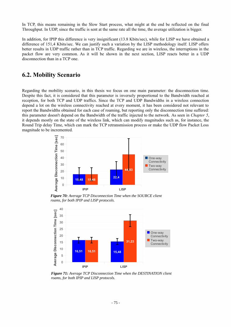
In TCP, this means remaining in the Slow Start process, what might at the end be reflected on the final Throughput. In UDP, since the traffic is sent at the same rate all the time, the average utilization is bigger.
In addition, for IPIP this difference is very insignificant (13.8 Kbits/sec), while for LISP we have obtained a difference of 151,4 Kbits/sec. We can justify such a variation by the LISP methodology itself: LISP offers better results in UDP traffic rather than in TCP traffic. Regarding we are in wireless, the interruptions in the packet flow are very common. As it will be shown in the next section, LISP reacts better in a UDP disconnection than in a TCP one.
6.2. Mobility Scenario
Regarding the mobility scenario, in this thesis we focus on one main parameter: the disconnection time. Despite this fact, it is considered that this parameter is inversely proportional to the Bandwidth reached at reception, for both TCP and UDP traffics. Since the TCP and UDP Bandwidths in a wireless connection depend a lot on the wireless connectivity reached at every moment, it has been considered not relevant to report the Bandwidths obtained for each case of roaming, but reporting only the disconnection time suffered: this parameter doesn't depend on the Bandwidth of the traffic injected to the network. As seen in Chapter 5, it depends mostly on the state of the wireless link, which can modify magnitudes such as, for instance, the Round Trip delay Time, which can mark the TCP retransmission process or make the UDP flow Packet Loss magnitude to be incremented.
- 75 -
Figure 70: Average TCP Disconnection Time when the SOURCE client roams, for both IPIP and LISP protocols.
Figure 71: Average TCP Disconnection Time when the DESTINATION client roams, for both IPIP and LISP protocols.
IPIP LISP
0
5
10
15
20
25
30
35
40
16,51 15,4816,51
31,23
One-way ConnectivityTwo-way Connectivity
Ave
rag
e D
isc
on
ne
cti
on
Tim
e [
se
c]
IPIP LISP
0
10
20
30
40
50
60
70
15,4822,4
15,48
44,83
One-way ConnectivityTwo-way Connectivity
Ave
rag
e D
isc
on
ne
cti
on
Tim
e [
se
c]

As shown in Figure 70, we can explain the increment of the LISP unidirectional disconnection time in comparison to the IPIP Disconnection time for a source client roaming by the LISP mapping system.: for IPIP, this time depends just on the wireless roaming time, because after it and considering no wireless connectivity issues, the first Retransmission packet is well routed to the receiver. Instead, in the LISP the mapping process needed in the new ITR to map the destination EID causes the dropping of the first retransmission packet sent, what can increase still a lot the disconnection time.
In the case of the destination roaming client shown in Figure 71, we can attribute to wireless connectivity issues the fact that the LISP unidirectional disconnection time is lower than the IPIP disconnection time. This time should be higher: in IPIP, the retransmission packets after the disconnection are sent to the old access point until the Node Manager updates the ITR's mesh_loc_table; in LISP though, there is an additional Map-Server registration time needed in the ETR before publishing the new EID-to-RLOC mapping, and so the information of the new destination client route is available later than in the IPIP case, what might cause the need of more retransmission packets.
Regarding TCP traffic, there is a substantial difference on how the LISP configuration reacts when the roaming process takes place compared with the IPIP configuration. As shown in Figures 70 and 71 above, in LISP there is a difference when re-establishing connection on one direction or on both. In IPIP, when the unidirectional TCP flow is re-established, that means the first packet reaches its destination after the roaming disconnection, it does also the bidirectional traffic; this fact is caused because the Acknowledgement of the first Retransmission arriving at the destination client always is sent back successfully to the sender. In LISP, instead, the Acknowledgement of the first Retransmission that arrives to the receiver after the disconnection is always dropped due to the LISP mechanism implemented. This makes the necessity of another Retransmission packet and the consequent duplication of the TCP flow disconnection time. However, after a big disconnection the TCP flow is re-established, according to the condition stated in the LISP section of Section 5.1.2.1.1. The solution of this problem might be a subject of future developers.
Regarding UDP traffic, the results obtained for the disconnection time when the roaming process takes place are very similar for the IPIP and LISP configurations:
As shown in Figure 72, the average disconnection time in a source client roaming in the middle of his UDP flow is bigger in the LISP configuration. The reason of this fact is that in the LISP setup the LISP mapping process takes place in the new ITR in order to map the destination EID, while in the IPIP case the time needed to continue the UDP flow after the disconnection is just the wireless re-attachment time: the new access point has already the route for the destination client on its Click mesh_loc_table, because he doesn't change his mapping. Since this time is measured in the receiver, the disconnection time reported in the IPIP should be theoretically equal to the wireless disconnection time due to the re-attachment process.
- 76 -
Figure 72: Average UDP Disconnection Time in the receiver when the SOURCE client roams, for both IPIP and LISP protocols. LISP-CACHE Timeout of 30 seconds.
IPIP LISP
0
1
2
3
4
5
6
7
8
9
10
4,986,45
Ave
rag
e D
isc
on
ne
cti
on
Tim
e [
se
c]

Indeed, the difference between both average times in Figure 72 reflects the average delay of the LISP mapping process, in which a Map-Request is sent and a Map-Reply is received. In the measurements taken, this time is in average equal to 1.47 seconds. In addition, as it has been shown in the previous chapter, the LISP disconnection time does not depend on the LISP-CACHE Timeout parameter.
In the destination roaming case represented in Figure 73, it has been compared the IPIP disconnection time versus the LISP one with the LISP-CACHE Timeout set to 5 seconds, which reports the lowest disconnection times from all the values tested. In theory, the time obtained in the IPIP case should be lower than the one obtained for LISP, due to the fact that for IPIP it is only required the time of wireless roaming plus the time spent by the Node Manager to update the ITR's mesh_loc_table, while in the LISP case the minimum disconnection time is the one stated in Section 5.1.2.1.2, higher than the IPIP one. Thus, considering the fact that these measurements have been taken in different moments, it is possible that external factors can have increased the wireless roaming time in the IPIP case. However, both times are so similar tha t make both protocols comparable.
In conclusion, in this chapter the IP-in-IP and the LISP protocols have been tested in order to achieve real reasults. It is important to stand out that the LISP protocol itself is compounded by several more functionalities than the ones that have been considered in this thesis. For instance, as shown in Figure 6 the LISP header contains in the LISP Locator Status Bits the information about the reachability of the RLOCs that are in the same site, as a measure of ensuring reliability on the LISP mappings before encapsulating packets in LISP headers. Another example of a functionality that has not been taken in account in this project is the LISP Nonce, a field in the LISP header serving as well for determining reachability between an ITR and an ETR that are communicating bidirectionally. Thus, the LISP protocol contamplates some more other functionalities than the IP-in-IP protocol, which have not been taken in account when comparing both protocols. Indeed, that is why the LISP header is bigger than the IP-in-IP one, since it needs to store more information. However, despite the fact of avoiding this information for the measurements, in the implementation and in the comparison these bytes of extra information have been respected, as shown with the results obtained on Section 5.1.1.
Regarding the fact commented above, in the measurements taken in this project both IP-in-IP and LISP protocols have similar behaviors., with a better reaction in the IPIP configuration in the mobility scenario. Regardless the differences in Bandwidths due to the differences in the header length, it is important to reflect the fact that in wireless mobility the differences in both configurations are not caused by the protocols
- 77 -
Figure 73: Average UDP Disconnection Time in the receiver when the DESTINATION client roams, for both IPIP and LISP protocols. LISP-CACHE Timeout of 5 seconds.
IPIP LISP
0
2
4
6
8
10
12
14
16
11,729,67
Ave
rag
e D
isc
on
ne
cti
on
Tim
e [
se
c]

themselves, but for the mapping protocol applied on each configuration. For the IPIP configuration, the mapping system is based on the Node Manager architecture, which manages the routes on every ITR by means of the Node Controller process run on them. Thus, the advantages in mobility of this configuration are caused not by the IP-in-IP protocol itself – which only describes the tunneling mechanism – but by the BOWL's management architecture. In the case of the LISP configuration, the mapping system used is a mix between the LISP Mapping System implemented – by means of the Map-Server – and the Node Manager architecture as well; the last one has been used to update the LISP-DB table when a client attaches to the node, which also can be considered as mapping information.
- 78 -
7. CONCLUSIONS
Along this thesis, the LISP protocol and a LISP Mapping System has been implemented and set up in a wireless network with the goal of research.
In summary, the final application of the code that has been implemented is to configure Click routers or access points. As described in Section 3.1.1, the Click Routers main advantages are the platform it provides to the researchers in order to configure it, and the fact that a Click Router can develop functionalities which normal routers cannot, such as, in the case of this project, implementing a network protocol. Thus, the most high-level source that has been build up is the Click script running on every LISP access point. Focusing on this Click script, regarding the fact that every Click element is implemented as a C++ class, the n ecessity to provide every router with the main LISP functionalities is the reason why the LISP-Click elements have been developed. Between the LISP-Click elements described in Section 4.2.2.1, we have to highlight the LISPEncapReq element because it's the one that has the power of decision regarding the LISP-encapsulation and the LISP Mapping processes: considering that the LISP site deployed has to support several kind of traffic, this element not only takes charge of encapsulating packets, but whether to encapsulate or not, to route them, and, in case the LISP Mapping System action is needed, to create LISP Map-Request packets. Also, this element is the responsible for the Extra Map-Request LISP mechanism, developed expressly by the necessity to re-establish TCP traffic flows when the wireless roaming process of the LISP clients takes place.
Regarding the LISP Mapping System developed in this thesis, the LISP Map-Server, implemented in Python, takes the role of manager in the mapping process. Doted with multi-threaded requests attention, it can handle all the LISP map requesters at the same time, as well as all the registration processes on behalf of the LISP access points. However, the LISP Mapping System deployed is sustained by the BOWL platform, more precisely by its management architecture: the Node Manager. It provides mapping update to the LISP access points regarding to the clients, and is a fundamental factor for developing wireless mobility. So far, for the LISP mapping system developement, it is required to have an external process running, which updates the LISP-DB tables of every access point when needed; in order to deploy this task, a little part of the BOWL management code has been modified, more specifically the Click Adaptor process source, described in Section 4.4.1.
The code implemented has been tested comparing it to the default BOWL IP-in-IP configuration. Exactly the same measurements done for the LISP configuration have been repeated for the IP-in-IP setup. This has been done not only for the goal of achieving a substantial comparison between two protocols that have many things in common – like tunneling – but to accredit the results obtained in the LISP implementation with an example of wireless network configuration that has been already researched and confirmed as the default configuration of the Deutsche Telekom BOWL project.
From the results obtained in the evaluation of the implementation carried out in Chapter 5 and considering the goals stated at the beginning of this report, several conclusions can be derived.
Firstly, regarding the static scenario for Local traffic described in Section 5.1, it has been double-checked the influence of the LISP Jack-up in terms of Bandwidth, as described in Section 2.1.1. The LISP protocol adds an additional Network Layer as a direct result of the tunneling performance. In terms of data packets, this process means perpending an additional IP header to the packets. With the results obtained, it has been verified that a traffic flow in which packets have a bigger header implies the decrease of the Bandwidth received, by comparing both the UDP and TCP flows for the IP-in-IP and LISP configurations. Of course, the IP-in-IP protocol is also a Jack-up, since it also adds an additional IP header to the packets; however, since
- 79 -

the LISP header length is bigger than the IP-in-IP one, the inversely proportional relationship between header length and connection bandwidth has been double-checked.
Secondly, one of the main goals of this thesis was to research in the wireless mobility domain. In regard to the mobility scenario described in Section 5.1.2 and the results obtained, different conclusions can be extracted. Considering the comparison between TCP and UDP traffic, it has been proved that in both IPIP and LISP configurations the disconnection time due to roaming is lower when transferring UDP traffic. The cause of this fact is the TCP Congestion protocol, which marks the disconnection time suffered in a TCP disconnection. In the case of LISP, despite the Extra Map-Request mechanism implemented, the disconnection time is still bigger, what is left in this thesis as an open point for improvement. So far, after this results we can state that in a wireless mobility environment the LISP protocol has better behavior acting with UDP traffic, because it reacts better under disconnections. Even on the static case, the UDP results are better than the TCP, what is caused by the fact that on a wireless network, a lot of external factors coming from the environment can cause up and downs in the traffic flow, and even disconnections.
Regarding the comparison between the IP-in-IP and LISP configurations, on the mobility domain the IP-in-IP setup report better results: the disconnection times measured in almost all the roaming cases are lower than the LISP ones. We can state that this fact is not due to the IP-in-IP protocol itself, but on the BOWL management system carried out by the Node Manager. Then, the advantages reported in the IPIP configuration respect in the LISP one remain in the differences between mapping system used in both cases. On a wireless mesh network setup with the default BOWL IPIP configuration, all the access points have at all times the routes of all the clients attached to the network on their mesh location table, which has the role of routing table. In LISP, though, the equivalent routing table is the LISP-CACHE, and every access point only has on its CACHE the routes of some specific clients, the ones that are at a specific time communicating with them. On the scenario developed, where there are just 9 access points, this fact has no relevance, but if we scale both configurations to bigger networks with a lot of clients, such as the Internet, the BOWL mapping system could have disadvantages respect to the LISP one, because while in the LISP one the Map-Server only handles specific requests, the equivalent Node Manager in the IPIP configuration broadcasts all the routes of all the clients to all the access points at the same time, causing a possible saturation of the mapping system. However, this fact is not contemplated in the results obtained, and even less if the process that updates the LISP-DB when a client roams is the same Node Manager, which contacts the same way all the nodes when a client attaches to the network by means of the Callbacks. An idea for future investigation would be to implement the LISP mapping system avoiding using the BOWL management unit in order to see the differences.
Thirdly, another goal proposed in this thesis was to implement a LISP Mapping System based on the open specification [LISP-MS]. In overview, the system that has been deployed performs the creation of the LISP Map-Server, a network component that has a centralized database where EID-to-RLOC mappings are stored. These mappings are updated by means of LISP Map-Register packets received from the ETRs, and published by LISP-Map-Replies messages to the ITRs which have requested them using LISP Map-Requests packets. The LISP Mapping System includes also on every access point the existence of two routing tables: the LISP-DB, which stores local EIDs, and the LISP-CACHE, which stores remote EID mappings within a time limited by the CACHE Timeout parameter. It is important to underline the relevance of this parameter in the LISP configuration build up in this project: as seen in Chapter 5, depending on its value different results are obtained. First of all, regarding TCP traffic, the LISP setup offers better results when this parameter has a high value, because in case of interruptions in the TCP flow, the Extra-Map-Request process takes place as a result of the TCP Congestion protocol, and then, according to the condition stated in Section 5.1.2.1.1, as larger is this value more TCP Retransmission packets can be sent to re-establish the connection. Second, in regarding UDP traffic, the LISP setup has better behavior in the mobility scenario for low values of this parameter, as it has been verified in Section 5.1.2.1.2. Considering this facts, the wireless mobility is almost completely determined by this parameter, limiting its improvement. So far, we can state that to timeout the LISP CACHE entries is not the best solution regarding wireless mobility, since in a real wireless site, both UDP and TCP traffics are present at all times and the CACHE Timeout cannot be modified in regards of the traffic sent at a specific moment. As a result of this, it is encouraged for future LISP developers to consider this fact.
- 80 -

Also, the LISP Extra-Map-Request implementation is a good solution to face the TCP congestion control mechanism in the roaming process, but in the LISP configuration deployed in this thesis it marks the need of a high LISP CACHE Timeout for TCP traffic. The main problem of the bad behavior of the LISP setup in front of TCP disconnections, as it has been seen in Section 5.1.2.1.1 comparing to the IPIP setup, remains on the LISP map-n-encap methodology: when an ITR needs a mapping for an EID, it sends a LISP Map-Request; while the consequent Map-Reply does not arrive, all the packets requesting the same EID are dropped. This fact limits the TCP congestion protocol since most of the TCP Retransmission packets may be dropped, what consequently limits mobility. As well, regarding mobility, a good solution would be to improve this methodology for queuing the packets instead of dropping them, being an open subject for further investigation.
In addition, there is another LISP parameter which, in regards of the measurements made, can be determinant when setting up a wireless mobility scenario: the LISP Mapping registration period time. Despite the fact that the [LISP-MS] suggests a specific value for this parameter, in the LISP mobility setup performed in this thesis it has been double-checked that mobility improves with its decrease. As shown for the UDP traffic case in Section 5.1.2.1.2, the disconnection time suffered in the traffic flow when roaming depends on this parameter, making it directly proportional to the disconnection time. In this manner, we can state that the LISP registration period time of the LISP ETRs marks completely the LISP mobility, and we let it as well as an open door for further investigation.
Finally, it is important to stand out that the main objective of this thesis has been achieved: the implementation of the LISP protocol in a wireless network and the setup of the conditions to carry out a research for the wireless mobility domain. To close this thesis, it is important to remind that all the work done for reaching the goals proposed on this project might be used for future researchers on the LISP Wireless domain.
- 81 -

8. REFERENCES
[LISP] Farinacci, D., Fuller, V., Meyer, D., and D. Lewis, "Locator/ID Separation Protocol (LISP)", draft-ietf-lisp-09.txt (work in progress), October 2010.
[LISP-MS] Farinacci, D. and V. Fuller, “LISP Map Server”,draft-ietf-lisp-ms-05.txt (work in progress), April 2010
[INTERWORK] Lewis, D., Meyer, D., Farinacci, D., and V. Fuller,“Interworking LISP with Ipv4 and Ipv6”,draft-ietf-lisp-interworking-01.txt (work in progress), March 2010.
[ALT] Farinacci, D., Fuller, V., Meyer, D., and D. Lewis, “LISP Alternative Topology (LISP-ALT)”,draft-ietf-lisp-alt-04.txt (work in progress), April 2010.
[CO NS] Farinacci, D., Fuller, V., and D. Meyer, "LISP-CONS: A Content distribution Overlay Network Service for LISP", draft-meyer-lisp-cons-03.txt (work in progress), November 2007.
[NERD] Lear, E., "NERD: A Not-so-novel EID to RLOC Database", draft-lear-lisp-nerd-08.txt (work in progress), March 2010.
[LISPDHT] Mathy, L., Iannone, L., and O. Bonaventure, "LISP-DHT: Towards a DHT to map identifiers onto locators",
draft-mathy-lisp-dht-00.txt (work in progress), Feb 2008.
[1] Jakab, L., Cabellos-Aparicio, A,, Coras, F., Saucez, D., and Bonaventure , O.,“LISP-TREE: A DNS Hierarchy to Support the LISP Mapping System ”, 2010.
[2] http://blog.ine.com/2010/07/05/a-high-level-overview-of-lisp/
[3] http://www.lisp4.net
[4] http://www.cisco.com/web/about/ac123/ac147/archived_issues/ipj_11-1/111_lisp.html
[5] http://www.tcpdump.org/
[6] http://www.wireshark.org/
[7] http://en.wikipedia.org/wiki/Iperf
[8] http://wget.addictivecode.org/
[9] “The Click Modular Router Project”http://read.cs.ucla.edu/click/click
- 82 -

[10] http://openwrt.org/[11] Merz, R., Schiöberg, H., Sengul C.,
“Design of a Configurable Wireless Network Testbed with Live Traffic”,May 2010
[12] http://www.bowl.tu-berlin.de/
[13] Saucez, D., Nguyen, V. N., “LISP-Click: A Click implementation of the Locator/ID Separation Protocol”,November 2009
[14] Iannone, L., Saucez, D., Bonaventure, O., “Implementing the Locator/ID Separation Protocol: Design and experience”,March 2011
- 83 -


![May the LISP be with You - Nerd2NerdWhy Lisp? More on Macros [ What Lisp?, How Lisp? ]Problems/Features [ When Lisp? ] May the LISP be with You Andrew (kqb) Easton nerd2nerd: nerdend](https://img.pdfslide.us/doc/110x75/5ed9946d1b54311e7967d3e5/may-the-lisp-be-with-you-nerd2nerd-why-lisp-more-on-macros-what-lisp-how.jpg)